Review of Basic Electrical and Magnetic Circuit Concepts EE
|
|
|
- Charity Rich
- 6 years ago
- Views:
Transcription
1 Review of Basic Electrical and Magnetic Circuit Concepts EE
2 Sinusoidal Linear Circuits: Instantaneous voltage, current and power, rms values
3 Average (real) power, reactive power, apparent power, power factor
4 Instantaneous power in pure resistive and inductive circuits
5 Phasor notation, impedance and admittance Transformation of a sinusoidal signal to and from the time domain to the phasor domain: v( t) 2V cos( t v) (time domain) V V (phasor domain) v
6 Resistive-Inductive, resistive-capacitive Load R R
7 Power in inductive and capacitive circuits
8 Complex Power, power triangle
9 Example: Power Factor Correction The power triangle below shows that the power factor is corrected by a shunt capacitor from 65% to 90% (lag). I L P m Q L Q m R L P m Q c I c 49.5 o
10 Conservation of power o At every node (bus) in the system, o the sum of real powers entering the node must be equal to the sum of real powers leaving that node. o The same applies for reactive power, o The same applies for complex power o The same does not apply for apparent power o The above is a direct consequence of Kirchhoff s current law, which states that the sum of the currents flowing into a node must equal the sum of the currents flowing out of that node.
11 Balanced 3 Phase Circuits Bulk power systems are almost exclusively 3-phase. Single phase is used primarily only in low voltage, low power settings, such as residential and some commercial customers. Some advantages of three-phase system: Can transmit more power for the same amount of wire (twice as much as single phase) Torque produced by 3 machines is constant, easy start. Three phase machines use less material for same power rating Real, reactive and complex power in balanced 3-phase circuits
12 Example: power factor correction In three-phase circuit m m PF P m = 3x4x0.462xcos(25.8 o )= 2.88 MW Q m = 3x4x0.462xsin(25.8 o )= 1.39 MVAR Q c = 1.8 MVAR Q L = Q m - Q c = MVAR
13 Power electronic circuits are non-linear Periodic waveforms but often not sinusoidal analytical expressions in terms of Fourier components
14 Fourier Analysis

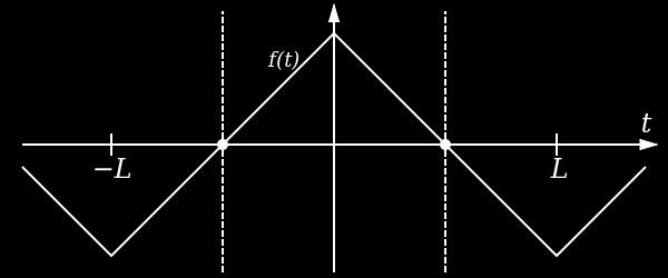
15 Example of simple non-sinusoidal periodic signals
16 Current decomposition Current decomposition of into fundamental (i s1 ) and distortion current (i dis ): ) / arctan(, 2, ) cos( 2 ) sin( ) cos( ) ( ) ( ) ( ) ( ) ( ) ( h h h h h sh h sh h h sh dis s h sh s s a b b a I Herein t h I t h b t h a t i where t i t i t i t i t i
17 RMS Value and Total Harmonic Distortion The rms value of a distorted waveform is equal to the squareroot of the sum of the square of the rms value of each harmonic component (including the fundamental). I s I I s1 sh s1 dis h1 I I Total Harmonic Distortion THD (%) 100 I I dis s1 100 I 2 s I s1 I 2 s1
18 Power and Power Factor Average (real) power and reactive powers: P Apparent Power: S V s I s P 2 Q 2 D 2 Q h0,1,... h0,1,... V h I V h I sh sh cos( ) h sin( ) h Power factor: PF P S Case of sinusoidal voltage and non-sinusoidal current: P V I cos( 1), Q Vs 1I s1 sin( 1) s1 s1 PF V s1 I s1 cos( 1) V I s1 s I I s1 s cos( ) 1 I I s1 s DPF 1 1 ( THD) 2 DPF Displacement Power Factor: DPF cos( 1 )
19 Example A 460 V, 60 Hz AC source supplies power to a 14.1 Ω resistive load. The load current is delayed by 81 degrees by a back-to-back thyristor circuit as shown to the right. Compute the following: a) rms values of the current b) magnitude and phase angle of the 60 Hz current component. c) Magnitude of the 3 rd and 5 th harmonic components, d) Active power, fundamental reactive power. e) Displacement power factor and overall power factor. Solution: a) A, b) 22 A, - 27 deg, c) 8.9 A, 3.7 A, d) 9 kw, 4.6 kvar, e) 89% and 77.4%
20 Ripple of DC Signal Ripple factor may be defined as the ratio of the root mean square (rms) value of the ripple signal to the absolute value of the DC component of the signal, usually expressed as a percentage. Rippleis also commonly expressed as the peak-to-peak value relative to the DC value.
21 Current-voltage in an inductor and capacitor In an inductor, the voltage is proportional to the rate of change of current. In a capacitor, the current is proportional to the rate of change of voltage. t d v d i C t d i d v L ) ( ) ( t i d t t v L i t t ) ( t v t d i C v t t
 t o T t v d t 0 Volt-seconds over T = 0 Area A = Area B")
22 Inductor response in steady-state At steady-state, i t + T = i(t) t o T t v d t 0 Volt-seconds over T = 0 Area A = Area B 0

23 Capacitor response in steady-state At steady-state, v t + T = v t t o T t 0 i d t 0 Amp-seconds over T = 0 Area A = Area B

24 Ampere s Law Ampère's circuital law, discovered by André-Marie Ampère in 1826, relates the integrated magnetic field around a closed loop to the electric current passing through the loop. H. dl net where H is the magnetic field intensity At a distance r from the wire, I H. dl H.(2r ) I
25 Magnetic Flux Density Relation between magnetic field intensity H and magnetic field density B: where B H r ) H ( 0 μ r is the relative permeability of the medium (unitless), μ o is the permeability of free space (= 4πx10-7 H/m)
26 B-H Curve in air and non-ferromagnetic material
27 Magnetic Flux Magnetic flux is the total flux within a given area. It is obtained by integrating the flux density over this area: BdA If the flux density is constant throughout the area, then, BA


28 Ampere s Law applied to a magnetic circuit (Solid Core) Ampere s law: H. dl Hl B l Where l is the average length of the flux path. The Magnetic flux is: NI B da BA Where A is the cross sectional area of the core. Hence, NI l ( A )
29 Analogous electrical and magnetic circuit quantities
 NI NI l B l B l H H l dl H a o c o r a a c c.")
30 Ampere s Law applied to a magnetic circuit (core with air gap - ignore leakage flux and fringing effect) NI NI l B l B l H H l dl H a o c o r a a c c. A l A l o a o r c where
31 B-H Curve of Ferromagnetic materials
32 Orientation of magnetic domains without and with the presence of an external magnetic field Without external magnetic field With external magnetic fiedl
33 Saturation curves of magnetic and nonmagnetic materials
34 Residual induction and Coercive Force
35 Hysteresis Loop traced by the flux in a core under AC current
36 Eddy currents are induced in a solid metal plate under the presence of a varying magnetic field
37 Solid iron core carrying an AC flux (significant eddy current flow and power loss)
38 Core built up of insulated laminations minimizes eddy currents (and eddy current losses)
39 Faraday s Law Faraday's law of induction is a basic law of electromagnetism relating to the operating principles of transformers, electrical motors and generators. The law states that: The induced electromotive force (EMF) in any closed circuit is equal to the time rate of change of the magnetic flux through the circuit Or alternatively, the EMF generated is proportional to the rate of change of the magnetic flux. e N d dt
40 Voltage induced in a coil when it links a variable flux in the form of a sinusoid
 l cos where θ is the angle between vxb and the velocity vector, and φ is the angle between vxb and the wire. The polarity of the induced voltage is determined by Lenz s Law. 90deg.")
41 Induced voltage in a conductor moving in a magnetic field The voltage induced in a conductor of length l that is moving in a magnetic field with flux density B, at a speed v is given by e ( vbsin ) l cos where θ is the angle between vxb and the velocity vector, and φ is the angle between vxb and the wire. The polarity of the induced voltage is determined by Lenz s Law. 90deg. and 0deg e Bvl
42 Induced voltage in a coil by a rotating magnet e

43 Lenz s Law The polarity of the induced voltage is such that it produced a current whose magnetic field opposes the change which produces it.
44 Inductance of a coil e L di dt N d dt N d( NiA / l) dt ( N 2 A / l) di dt L N A l 2

45 Induced force on a current-carrying conductor The force on a wire of length l and carrying a current i under the presence of a magnetic flux B is given by F Bil sin where θ is the angle between the wire and flux density vector. The direction of the force is determined by the right hand rule
46 Transformers

47 High-frequency vs. Low-frequency transformers For a given supply voltage, the flux density B in a transformer core is: Inversely proportional to supply frequency Inversely proportional to the cross-sectional area of the core. As the operating frequency increases, we can use less turns and a smaller core cross-sectional area. So a high-frequency transformer is smaller than a low frequency transformer of the same power rating. However, hysteresis losses in the core will increase with frequency if the flux density is kept constant. So for high frequency transformers, we ditch the laminated iron core and use a ferrite material. This needs to be operated at a lower flux density than iron but exhibits low hysteresis losses. Example: 60 Hz, 120/24 V, 36 VA, B = 1.5 T, core loss = 1 W, N1/N2 = 600/120, weight = 500 g. 6 khz, 120/24, 480 VA, B = 0.2 T, core loss = 1 W, N1/N2 = 45/9, weight = 100 g.
SECOND ENGINEER REG III/2 MARINE ELECTRO-TECHNOLOGY. 1. Understands the physical construction and characteristics of basic components.
 SECOND ENGINEER REG III/ MARINE ELECTRO-TECHNOLOGY LIST OF TOPICS A B C D Electric and Electronic Components Electric Circuit Principles Electromagnetism Electrical Machines The expected learning outcome
Electronic Power Conversion
 Electronic Power Conversion Review of Basic Electrical and Magnetic Circuit Concepts Challenge the future 3. Review of Basic Electrical and Magnetic Circuit Concepts Notation Electric circuits Steady state
Sinusoidal Response of RLC Circuits
 Sinusoidal Response of RLC Circuits Series RL circuit Series RC circuit Series RLC circuit Parallel RL circuit Parallel RC circuit R-L Series Circuit R-L Series Circuit R-L Series Circuit Instantaneous
EE 212 PASSIVE AC CIRCUITS
 EE 212 PASSIVE AC CIRCUITS Condensed Text Prepared by: Rajesh Karki, Ph.D., P.Eng. Dept. of Electrical Engineering University of Saskatchewan About the EE 212 Condensed Text The major topics in the course
MAGNETIC CIRCUITS. Magnetic Circuits
 Basic Electrical Theory What is a magnetic circuit? To better understand magnetic circuits, a basic understanding of the physical qualities of magnetic circuits will be necessary. EO 1.8 EO 1.9 EO 1.10
ROEVER COLLEGE OF ENGINEERING & TECHNOLOGY ELAMBALUR, PERAMBALUR DEPARTMENT OF ELECTRICAL AND ELECTRONICS ENGINEERING ELECTRICAL MACHINES I
 ROEVER COLLEGE OF ENGINEERING & TECHNOLOGY ELAMBALUR, PERAMBALUR-621220 DEPARTMENT OF ELECTRICAL AND ELECTRONICS ENGINEERING ELECTRICAL MACHINES I Unit I Introduction 1. What are the three basic types
Module 3 Electrical Fundamentals
 3.1 Electron Theory Structure and distribution of electrical charges within: atoms, molecules, ions, compounds; Molecular structure of conductors, semiconductors and insulators. 3.2 Static Electricity
Chapter 15 Magnetic Circuits and Transformers
 Chapter 15 Magnetic Circuits and Transformers Chapter 15 Magnetic Circuits and Transformers 1. Understand magnetic fields and their interactio with moving charges. 2. Use the right-hand rule to determine
Part 4: Electromagnetism. 4.1: Induction. A. Faraday's Law. The magnetic flux through a loop of wire is
 1 Part 4: Electromagnetism 4.1: Induction A. Faraday's Law The magnetic flux through a loop of wire is Φ = BA cos θ B A B = magnetic field penetrating loop [T] A = area of loop [m 2 ] = angle between field
Ch. 23 Electromagnetic Induction, AC Circuits, And Electrical Technologies
 Ch. 23 Electromagnetic Induction, AC Circuits, And Electrical Technologies Induced emf - Faraday s Experiment When a magnet moves toward a loop of wire, the ammeter shows the presence of a current When
ELECTROMAGNETIC OSCILLATIONS AND ALTERNATING CURRENT
 Chapter 31: ELECTROMAGNETIC OSCILLATIONS AND ALTERNATING CURRENT 1 A charged capacitor and an inductor are connected in series At time t = 0 the current is zero, but the capacitor is charged If T is the
An Introduction to Electrical Machines. P. Di Barba, University of Pavia, Italy
 An Introduction to Electrical Machines P. Di Barba, University of Pavia, Italy Academic year 0-0 Contents Transformer. An overview of the device. Principle of operation of a single-phase transformer 3.
Lecture 11 - AC Power
 - AC Power 11/17/2015 Reading: Chapter 11 1 Outline Instantaneous power Complex power Average (real) power Reactive power Apparent power Maximum power transfer Power factor correction 2 Power in AC Circuits
R. W. Erickson. Department of Electrical, Computer, and Energy Engineering University of Colorado, Boulder
 R. W. Erickson Department of Electrical, Computer, and Energy Engineering University of Colorado, Boulder Part III. Magnetics 13 Basic Magnetics Theory 14 Inductor Design 15 Transformer Design 1 Chapter
Work, Energy and Power
 1 Work, Energy and Power Work is an activity of force and movement in the direction of force (Joules) Energy is the capacity for doing work (Joules) Power is the rate of using energy (Watt) P = W / t,
11. AC Circuit Power Analysis
 . AC Circuit Power Analysis Often an integral part of circuit analysis is the determination of either power delivered or power absorbed (or both). In this chapter First, we begin by considering instantaneous
The initial magnetization curve shows the magnetic flux density that would result when an increasing magnetic field is applied to an initially
 MAGNETIC CIRCUITS The study of magnetic circuits is important in the study of energy systems since the operation of key components such as transformers and rotating machines (DC machines, induction machines,
RLC Circuit (3) We can then write the differential equation for charge on the capacitor. The solution of this differential equation is
 We can then write the differential equation for charge on the capacitor. The solution of this differential equation is") RLC Circuit (3) We can then write the differential equation for charge on the capacitor The solution of this differential equation is (damped harmonic oscillation!), where 25 RLC Circuit (4) If we charge
RLC Circuit (3) We can then write the differential equation for charge on the capacitor The solution of this differential equation is (damped harmonic oscillation!), where 25 RLC Circuit (4) If we charge
Lecture Notes ELEC A6
 Lecture Notes ELEC A6 Dr. Ramadan El-Shatshat Magnetic circuit 9/27/2006 Elec-A6 - Electromagnetic Energy Conversion 1 Magnetic Field Concepts Magnetic Fields: Magnetic fields are the fundamental mechanism
Alternating Current Circuits
 Alternating Current Circuits AC Circuit An AC circuit consists of a combination of circuit elements and an AC generator or source. The output of an AC generator is sinusoidal and varies with time according
Transformer Fundamentals
 Transformer Fundamentals 1 Introduction The physical basis of the transformer is mutual induction between two circuits linked by a common magnetic field. Transformer is required to pass electrical energy
Power Factor Improvement
 Salman bin AbdulazizUniversity College of Engineering Electrical Engineering Department EE 2050Electrical Circuit Laboratory Power Factor Improvement Experiment # 4 Objectives: 1. To introduce the concept
Sliding Conducting Bar
 Motional emf, final For equilibrium, qe = qvb or E = vb A potential difference is maintained between the ends of the conductor as long as the conductor continues to move through the uniform magnetic field
Lecture 24. April 5 th, Magnetic Circuits & Inductance
 Lecture 24 April 5 th, 2005 Magnetic Circuits & Inductance Reading: Boylestad s Circuit Analysis, 3 rd Canadian Edition Chapter 11.1-11.5, Pages 331-338 Chapter 12.1-12.4, Pages 341-349 Chapter 12.7-12.9,
Chapter 1 Magnetic Circuits
 Principles of Electric Machines and Power Electronics Third Edition P. C. Sen Chapter 1 Magnetic Circuits Chapter 1: Main contents i-h relation, B-H relation Magnetic circuit and analysis Property of magnetic
Refresher course on Electrical fundamentals (Basics of A.C. Circuits) by B.M.Vyas
 by B.M.Vyas") Refresher course on Electrical fundamentals (Basics of A.C. Circuits) by B.M.Vyas A specifically designed programme for Da Afghanistan Breshna Sherkat (DABS) Afghanistan 1 Areas Covered Under this Module
Refresher course on Electrical fundamentals (Basics of A.C. Circuits) by B.M.Vyas A specifically designed programme for Da Afghanistan Breshna Sherkat (DABS) Afghanistan 1 Areas Covered Under this Module
TRANSFORMERS B O O K P G
 TRANSFORMERS B O O K P G. 4 4 4-449 REVIEW The RMS equivalent current is defined as the dc that will provide the same power in the resistor as the ac does on average P average = I 2 RMS R = 1 2 I 0 2 R=
Module 4. Single-phase AC Circuits
 Module 4 Single-phase AC Circuits Lesson 14 Solution of Current in R-L-C Series Circuits In the last lesson, two points were described: 1. How to represent a sinusoidal (ac) quantity, i.e. voltage/current
Book Page cgrahamphysics.com Transformers
 Book Page 444-449 Transformers Review The RMS equivalent current is defined as the dc that will provide the same power in the resistor as the ac does on average P average = I 2 RMS R = 1 2 I 0 2 R= V RMS
EE 3120 Electric Energy Systems Study Guide for Prerequisite Test Wednesday, Jan 18, pm, Room TBA
 EE 3120 Electric Energy Systems Study Guide for Prerequisite Test Wednesday, Jan 18, 2006 6-7 pm, Room TBA First retrieve your EE2110 final and other course papers and notes! The test will be closed book
Chapter 1W Basic Electromagnetic Concepts
 Chapter 1W Basic Electromagnetic Concepts 1W Basic Electromagnetic Concepts 1W.1 Examples and Problems on Electric Circuits 1W.2 Examples on Magnetic Concepts This chapter includes additional examples
Magnetostatic fields! steady magnetic fields produced by steady (DC) currents or stationary magnetic materials.
 currents or stationary magnetic materials.") ECE 3313 Electromagnetics I! Static (time-invariant) fields Electrostatic or magnetostatic fields are not coupled together. (one can exist without the other.) Electrostatic fields! steady electric fields
ECE 3313 Electromagnetics I! Static (time-invariant) fields Electrostatic or magnetostatic fields are not coupled together. (one can exist without the other.) Electrostatic fields! steady electric fields
Pretest ELEA1831 Module 11 Units 1& 2 Inductance & Capacitance
 Pretest ELEA1831 Module 11 Units 1& 2 Inductance & Capacitance 1. What is Faraday s Law? Magnitude of voltage induced in a turn of wire is proportional to the rate of change of flux passing through that
Magnetism & Electromagnetism
 Magnetism & Electromagnetism By: Dr Rosemizi Abd Rahim Click here to watch the magnetism and electromagnetism animation video http://rmz4567.blogspot.my/2013/02/electrical-engineering.html 1 Learning Outcomes
Sinusoidal Steady State Analysis (AC Analysis) Part II
 Part II") Sinusoidal Steady State Analysis (AC Analysis) Part II Amin Electronics and Electrical Communications Engineering Department (EECE) Cairo University elc.n102.eng@gmail.com http://scholar.cu.edu.eg/refky/
Sinusoidal Steady State Analysis (AC Analysis) Part II Amin Electronics and Electrical Communications Engineering Department (EECE) Cairo University elc.n102.eng@gmail.com http://scholar.cu.edu.eg/refky/
ELECTROMAGNETIC INDUCTION
 ELECTROMAGNETIC INDUCTION 1. Magnetic Flux 2. Faraday s Experiments 3. Faraday s Laws of Electromagnetic Induction 4. Lenz s Law and Law of Conservation of Energy 5. Expression for Induced emf based on
PHYS 1441 Section 001 Lecture #23 Monday, Dec. 4, 2017
 PHYS 1441 Section 1 Lecture #3 Monday, Dec. 4, 17 Chapter 3: Inductance Mutual and Self Inductance Energy Stored in Magnetic Field Alternating Current and AC Circuits AC Circuit W/ LRC Chapter 31: Maxwell
Electromagnetic Induction & Inductors
 Electromagnetic Induction & Inductors 1 Revision of Electromagnetic Induction and Inductors (Much of this material has come from Electrical & Electronic Principles & Technology by John Bird) Magnetic Field
Power and Energy Measurement
 Power and Energy Measurement EIE 240 Electrical and Electronic Measurement April 24, 2015 1 Work, Energy and Power Work is an activity of force and movement in the direction of force (Joules) Energy is
Get Discount Coupons for your Coaching institute and FREE Study Material at ELECTROMAGNETIC INDUCTION
 ELECTROMAGNETIC INDUCTION 1. Magnetic Flux 2. Faraday s Experiments 3. Faraday s Laws of Electromagnetic Induction 4. Lenz s Law and Law of Conservation of Energy 5. Expression for Induced emf based on
Assessment Schedule 2015 Physics: Demonstrate understanding of electrical systems (91526)
") NCEA Level 3 Physics (91526) 2015 page 1 of 6 Assessment Schedule 2015 Physics: Demonstrate understanding of electrical systems (91526) Evidence Q Evidence Achievement Achievement with Merit Achievement
NCEA Level 3 Physics (91526) 2015 page 1 of 6 Assessment Schedule 2015 Physics: Demonstrate understanding of electrical systems (91526) Evidence Q Evidence Achievement Achievement with Merit Achievement
PESIT Bangalore South Campus Hosur road, 1km before Electronic City, Bengaluru -100 Department of Electronics & Communication Engineering
 QUESTION PAPER INTERNAL ASSESSMENT TEST 2 Date : /10/2016 Marks: 0 Subject & Code: BASIC ELECTRICAL ENGINEERING -15ELE15 Sec : F,G,H,I,J,K Name of faculty : Dhanashree Bhate, Hema B, Prashanth V Time :
The simplest type of alternating current is one which varies with time simple harmonically. It is represented by
 ALTERNATING CURRENTS. Alternating Current and Alternating EMF An alternating current is one whose magnitude changes continuously with time between zero and a maximum value and whose direction reverses
ELEC ELE TRO TR MAGNETIC INDUCTION
 ELECTRO MAGNETIC INDUCTION Faraday Henry 1791-1867 1797 1878 Laws:- Faraday s Laws :- 1) When ever there is a change in magnetic flux linked with a coil, a current is generated in the coil. The current
Chapter 23 Magnetic Flux and Faraday s Law of Induction
 Chapter 23 Magnetic Flux and Faraday s Law of Induction 1 Overview of Chapter 23 Induced Electromotive Force Magnetic Flux Faraday s Law of Induction Lenz s Law Mechanical Work and Electrical Energy Generators
LO 1: Three Phase Circuits
 Course: EEL 2043 Principles of Electric Machines Class Instructor: Dr. Haris M. Khalid Email: hkhalid@hct.ac.ae Webpage: www.harismkhalid.com LO 1: Three Phase Circuits Three Phase AC System Three phase
Electromagnetic Field Theory Chapter 9: Time-varying EM Fields
 Electromagnetic Field Theory Chapter 9: Time-varying EM Fields Faraday s law of induction We have learned that a constant current induces magnetic field and a constant charge (or a voltage) makes an electric
EDEXCEL NATIONAL CERTIFICATE/DIPLOMA UNIT 5 - ELECTRICAL AND ELECTRONIC PRINCIPLES NQF LEVEL 3. OUTCOME 3 - MAGNETISM and INDUCTION
 EDEXCEL NATIONAL CERTIFICATE/DIPLOMA UNIT 5 - ELECTRICAL AND ELECTRONIC PRINCIPLES NQF LEVEL 3 OUTCOME 3 - MAGNETISM and INDUCTION 3 Understand the principles and properties of magnetism Magnetic field:
Definition Application of electrical machines Electromagnetism: review Analogies between electric and magnetic circuits Faraday s Law Electromagnetic
 Definition Application of electrical machines Electromagnetism: review Analogies between electric and magnetic circuits Faraday s Law Electromagnetic Force Motor action Generator action Types and parts
EXP. NO. 3 Power on (resistive inductive & capacitive) load Series connection
 load Series connection") OBJECT: To examine the power distribution on (R, L, C) series circuit. APPARATUS 1-signal function generator 2- Oscilloscope, A.V.O meter 3- Resisters & inductor &capacitor THEORY the following form for
OBJECT: To examine the power distribution on (R, L, C) series circuit. APPARATUS 1-signal function generator 2- Oscilloscope, A.V.O meter 3- Resisters & inductor &capacitor THEORY the following form for
15-884/484 Electric Power Systems 1: DC and AC Circuits
 15-884/484 Electric Power Systems 1: DC and AC Circuits J. Zico Kolter October 8, 2013 1 Hydro Estimated U.S. Energy Use in 2010: ~98.0 Quads Lawrence Livermore National Laboratory Solar 0.11 0.01 8.44
EEE3405 ELECTRICAL ENGINEERING PRINCIPLES 2 - TEST
 ATTEMPT ALL QUESTIONS (EACH QUESTION 20 Marks, FULL MAKS = 60) Given v 1 = 100 sin(100πt+π/6) (i) Find the MS, period and the frequency of v 1 (ii) If v 2 =75sin(100πt-π/10) find V 1, V 2, 2V 1 -V 2 (phasor)
FIRST TERM EXAMINATION (07 SEPT 2015) Paper - PHYSICS Class XII (SET B) Time: 3hrs. MM: 70
 Paper - PHYSICS Class XII (SET B) Time: 3hrs. MM: 70") FIRST TERM EXAMINATION (07 SEPT 205) Paper - PHYSICS Class XII (SET B) Time: 3hrs. MM: 70 Instructions:. All questions are compulsory. 2. Q.no. to 5 carry mark each. 3. Q.no. 6 to 0 carry 2 marks each.
FIRST TERM EXAMINATION (07 SEPT 205) Paper - PHYSICS Class XII (SET B) Time: 3hrs. MM: 70 Instructions:. All questions are compulsory. 2. Q.no. to 5 carry mark each. 3. Q.no. 6 to 0 carry 2 marks each.
Electromagnetism. 1 ENGN6521 / ENGN4521: Embedded Wireless
 Electromagnetism 1 ENGN6521 / ENGN4521: Embedded Wireless Radio Spectrum use for Communications 2 ENGN6521 / ENGN4521: Embedded Wireless 3 ENGN6521 / ENGN4521: Embedded Wireless Electromagnetism I Gauss
Revision Guide for Chapter 15
 Revision Guide for Chapter 15 Contents tudent s Checklist Revision otes Transformer... 4 Electromagnetic induction... 4 Generator... 5 Electric motor... 6 Magnetic field... 8 Magnetic flux... 9 Force on
12. Introduction and Chapter Objectives
 Real Analog - Circuits 1 Chapter 1: Steady-State Sinusoidal Power 1. Introduction and Chapter Objectives In this chapter we will address the issue of power transmission via sinusoidal or AC) signals. This
UNIVERSITY OF TECHNOLOGY, JAMAICA Faculty of Engineering and Computing School of Engineering
 UNIVERSITY OF TECHNOLOGY, JAMAICA Faculty of Engineering and Computing School of Engineering SYLLABUS OUTLINE FACULTY: SCHOOL/DEPT: COURSE OF STUDY: Engineering and Computing Engineering Diploma in Electrical
Power and Energy Measurement
 Power and Energy Measurement ENE 240 Electrical and Electronic Measurement Class 11, February 4, 2009 werapon.chi@kmutt.ac.th 1 Work, Energy and Power Work is an activity of force and movement in the direction
Switched Mode Power Conversion
 Inductors Devices for Efficient Power Conversion Switches Inductors Transformers Capacitors Inductors Inductors Store Energy Inductors Store Energy in a Magnetic Field In Power Converters Energy Storage
Induction_P1. 1. [1 mark]
![Induction_P1. 1. [1 mark]](/thumbs/88/115570773.jpg "Induction_P1. 1. [1 mark]") Induction_P1 1. [1 mark] Two identical circular coils are placed one below the other so that their planes are both horizontal. The top coil is connected to a cell and a switch. The switch is closed and
Induction_P1 1. [1 mark] Two identical circular coils are placed one below the other so that their planes are both horizontal. The top coil is connected to a cell and a switch. The switch is closed and
Work, Energy and Power
 1 Work, Energy and Power Work is an activity of force and movement in the direction of force (Joules) Energy is the capacity for doing work (Joules) Power is the rate of using energy (Watt) P = W / t,
Chapter 2: Fundamentals of Magnetism. 8/28/2003 Electromechanical Dynamics 1
 Chapter 2: Fundamentals of Magnetism 8/28/2003 Electromechanical Dynamics 1 Magnetic Field Intensity Whenever a magnetic flux, φ, exist in a conductor or component, it is due to the presence of a magnetic
Slide 1 / 24. Electromagnetic Induction 2011 by Bryan Pflueger
 Slide 1 / 24 Electromagnetic Induction 2011 by Bryan Pflueger Slide 2 / 24 Induced Currents If we have a galvanometer attached to a coil of wire we can induce a current simply by changing the magnetic
Name: Class: Date: Multiple Choice Identify the letter of the choice that best completes the statement or answers the question.
 Name: Class: _ Date: _ w9final Multiple Choice Identify the letter of the choice that best completes the statement or answers the question. 1. If C = 36 µf, determine the equivalent capacitance for the
1. An isolated stationary point charge produces around it. a) An electric field only. b) A magnetic field only. c) Electric as well magnetic fields.
 An electric field only. b) A magnetic field only. c) Electric as well magnetic fields.") 1. An isolated stationary point charge produces around it. a) An electric field only. b) A magnetic field only. c) Electric as well magnetic fields. 2. An isolated moving point charge produces around it.
1. An isolated stationary point charge produces around it. a) An electric field only. b) A magnetic field only. c) Electric as well magnetic fields. 2. An isolated moving point charge produces around it.
Introduction to AC Circuits (Capacitors and Inductors)
") Introduction to AC Circuits (Capacitors and Inductors) Amin Electronics and Electrical Communications Engineering Department (EECE) Cairo University elc.n102.eng@gmail.com http://scholar.cu.edu.eg/refky/
Introduction to AC Circuits (Capacitors and Inductors) Amin Electronics and Electrical Communications Engineering Department (EECE) Cairo University elc.n102.eng@gmail.com http://scholar.cu.edu.eg/refky/
Electrical Eng. fundamental Lecture 1
 Electrical Eng. fundamental Lecture 1 Contact details: h-elhelw@staffs.ac.uk Introduction Electrical systems pervade our lives; they are found in home, school, workplaces, factories,
Electromagnetic Induction and Faraday s Law
 Electromagnetic Induction and Faraday s Law Induced EMF Almost 200 years ago, Faraday looked for evidence that a magnetic field would induce an electric current with this apparatus: He found no evidence
Pre-Lab. Introduction
 Pre-Lab Read through this entire lab. Perform all of your calculations (calculated values) prior to making the required circuit measurements. You may need to measure circuit component values to obtain
EE 742 Chapter 3: Power System in the Steady State. Y. Baghzouz
 EE 742 Chapter 3: Power System in the Steady State Y. Baghzouz Transmission Line Model Distributed Parameter Model: Terminal Voltage/Current Relations: Characteristic impedance: Propagation constant: π
3 The non-linear elements
 3.1 Introduction The inductor and the capacitor are the two important passive circuit elements which have the ability to store and deliver finite amount of energy [49]. In an inductor, the energy is stored
Transformer. Transformer comprises two or more windings coupled by a common magnetic circuit (M.C.).
.") . Transformers Transformer Transformer comprises two or more windings coupled by a common magnetic circuit (M.C.). f the primary side is connected to an AC voltage source v (t), an AC flux (t) will be
. Transformers Transformer Transformer comprises two or more windings coupled by a common magnetic circuit (M.C.). f the primary side is connected to an AC voltage source v (t), an AC flux (t) will be
SYLLABUS(EE-205-F) SECTION-B
 SECTION-B") SYLLABUS(EE-205-F) SECTION-A MAGNETIC CIRCUITS AND INDUCTION: Magnetic Circuits, Magnetic Materials and their properties, static and dynamic emfs and dforce on current carrying conductor, AC operation
SYLLABUS(EE-205-F) SECTION-A MAGNETIC CIRCUITS AND INDUCTION: Magnetic Circuits, Magnetic Materials and their properties, static and dynamic emfs and dforce on current carrying conductor, AC operation
VTU E-LEARNING NOTES ON:
 VTU E-LEARNING NOTES ON: 10EE35 ELECTRICAL AND ELECTRONIC MEASUREMENTS AND INSTRUMENTATION BY DR. M.S. RAVIPRAKASHA PROFESSOR & HEAD DEPT. OF E&E ENGG. MALNAD COLLEGE OF ENGG. HASSAN 573 201. SUBJECT CODE
Revision Guide for Chapter 15
 Revision Guide for Chapter 15 Contents Revision Checklist Revision otes Transformer...4 Electromagnetic induction...4 Lenz's law...5 Generator...6 Electric motor...7 Magnetic field...9 Magnetic flux...
Mutual Inductance. The field lines flow from a + charge to a - change
 Capacitors Mutual Inductance Since electrical charges do exist, electric field lines have a starting point and an ending point. For example, if you have a + and a - change, the field lines would look something
General Physics (PHY 2140)
") General Physics (PHY 2140) Lecture 10 6/12/2007 Electricity and Magnetism Induced voltages and induction Self-Inductance RL Circuits Energy in magnetic fields AC circuits and EM waves Resistors, capacitors
General Physics (PHY 2140) Lecture 10 6/12/2007 Electricity and Magnetism Induced voltages and induction Self-Inductance RL Circuits Energy in magnetic fields AC circuits and EM waves Resistors, capacitors
COLLEGE PHYSICS Chapter 23 ELECTROMAGNETIC INDUCTION, AC CIRCUITS, AND ELECTRICAL TECHNOLOGIES
 COLLEGE PHYSICS Chapter 23 ELECTROMAGNETIC INDUCTION, AC CIRCUITS, AND ELECTRICAL TECHNOLOGIES Induced emf: Faraday s Law and Lenz s Law We observe that, when a magnet is moved near a conducting loop,
EELE 3332 Electromagnetic II Chapter 9. Maxwell s Equations. Islamic University of Gaza Electrical Engineering Department Dr.
 EELE 3332 Electromagnetic II Chapter 9 Maxwell s Equations Islamic University of Gaza Electrical Engineering Department Dr. Talal Skaik 2012 1 Review Electrostatics and Magnetostatics Electrostatic Fields
CHAPTER 22 ELECTROMAGNETIC INDUCTION
 CHAPTER 22 ELECTROMAGNETIC INDUCTION PROBLEMS 47. REASONING AND Using Equation 22.7, we find emf 2 M I or M ( emf 2 ) t ( 0.2 V) ( 0.4 s) t I (.6 A) ( 3.4 A) 9.3 0 3 H 49. SSM REASONING AND From the results
Part III. Magnetics. Chapter 13: Basic Magnetics Theory. Chapter 13 Basic Magnetics Theory
 Part III. Magnetics 3 Basic Magnetics Theory Inductor Design 5 Transformer Design Chapter 3 Basic Magnetics Theory 3. Review of Basic Magnetics 3.. Basic relationships 3..2 Magnetic circuits 3.2 Transformer
Chapter 5 Steady-State Sinusoidal Analysis
 Chapter 5 Steady-State Sinusoidal Analysis Chapter 5 Steady-State Sinusoidal Analysis 1. Identify the frequency, angular frequency, peak value, rms value, and phase of a sinusoidal signal. 2. Solve steady-state
ELECTRO MAGNETIC INDUCTION
 ELECTRO MAGNETIC INDUCTION 1) A Circular coil is placed near a current carrying conductor. The induced current is anti clock wise when the coil is, 1. Stationary 2. Moved away from the conductor 3. Moved
Basics of Electric Circuits
 António Dente Célia de Jesus February 2014 1 Alternating Current Circuits 1.1 Using Phasors There are practical and economic reasons justifying that electrical generators produce emf with alternating and
fusion production of elements in stars, 345
 I N D E X AC circuits capacitive reactance, 278 circuit frequency, 267 from wall socket, 269 fundamentals of, 267 impedance in general, 283 peak to peak voltage, 268 phase shift in RC circuit, 280-281
Magnetic Fields
 Magnetic circuits introduction Becomes aware of the similarities between the analysis of magnetic circuits and electric circuits. Develop a clear understanding of the important parameters of a magnetic
Sol: Semiconductor diode.
 48 49 1. What is the resistance value of a resistor of colour code Brown, Black, Red and silver? Sol: Brown-1, Black-0, Red-2, Silver- 10%. Resistance, R = 10 X 10-2 ±10Ω. 2. Mention a non-ohmic device.
DIRECT-CURRENT MOTORS
 CHAPTER 4 DIRECT-CURRENT MOTORS Chapter Contributors Andrew E. Miller Earl F. Richards Alan W. Yeadon William H. Yeadon This chapter covers methods of calculating performance for direct-current (dc) mechanically
SECTION 3 BASIC AUTOMATIC CONTROLS UNIT 12 BASIC ELECTRICITY AND MAGNETISM
 SECTION 3 BASIC AUTOMATIC CONTROLS UNIT 12 BASIC ELECTRICITY AND MAGNETISM Unit Objectives Describe the structure of an atom. Identify atoms with a positive charge and atoms with a negative charge. Explain
Gen. Phys. II Exam 2 - Chs. 21,22,23 - Circuits, Magnetism, EM Induction Mar. 5, 2018
 Gen. Phys. II Exam 2 - Chs. 21,22,23 - Circuits, Magnetism, EM Induction Mar. 5, 2018 Rec. Time Name For full credit, make your work clear. Show formulas used, essential steps, and results with correct
EXPERIMENT 07 TO STUDY DC RC CIRCUIT AND TRANSIENT PHENOMENA
 EXPERIMENT 07 TO STUDY DC RC CIRCUIT AND TRANSIENT PHENOMENA DISCUSSION The capacitor is a element which stores electric energy by charging the charge on it. Bear in mind that the charge on a capacitor
AQA Physics A-level Section 7: Fields and Their Consequences
 AQA Physics A-level Section 7: Fields and Their Consequences Key Points Gravitational fields A force field is a region in which a body experiences a non-contact force. Gravity is a universal force acting
Physics 54 Lecture March 1, Micro-quiz problems (magnetic fields and forces) Magnetic dipoles and their interaction with magnetic fields
 Magnetic dipoles and their interaction with magnetic fields") Physics 54 Lecture March 1, 2012 OUTLINE Micro-quiz problems (magnetic fields and forces) Magnetic dipoles and their interaction with magnetic fields Electromagnetic induction Introduction to electromagnetic
Physics 54 Lecture March 1, 2012 OUTLINE Micro-quiz problems (magnetic fields and forces) Magnetic dipoles and their interaction with magnetic fields Electromagnetic induction Introduction to electromagnetic
ELECTRIC POWER CIRCUITS BASIC CONCEPTS AND ANALYSIS
 Contents ELEC46 Power ystem Analysis Lecture ELECTRC POWER CRCUT BAC CONCEPT AND ANALY. Circuit analysis. Phasors. Power in single phase circuits 4. Three phase () circuits 5. Power in circuits 6. ingle
Chapter 23 Magnetic Flux and Faraday s Law of Induction
 Chapter 23 Magnetic Flux and Faraday s Law of Induction Recall: right hand rule 2 10/28/2013 Units of Chapter 23 Induced Electromotive Force Magnetic Flux Faraday s Law of Induction Lenz s Law Mechanical
r where the electric constant
 1.0 ELECTROSTATICS At the end of this topic, students will be able to: 10 1.1 Coulomb s law a) Explain the concepts of electrons, protons, charged objects, charged up, gaining charge, losing charge, charging
SUMMARY Phys 2523 (University Physics II) Compiled by Prof. Erickson. F e (r )=q E(r ) dq r 2 ˆr = k e E = V. V (r )=k e r = k q i. r i r.
 Compiled by Prof. Erickson. F e (r )=q E(r ) dq r 2 ˆr = k e E = V. V (r )=k e r = k q i. r i r.") SUMMARY Phys 53 (University Physics II) Compiled by Prof. Erickson q 1 q Coulomb s Law: F 1 = k e r ˆr where k e = 1 4π =8.9875 10 9 N m /C, and =8.85 10 1 C /(N m )isthepermittivity of free space. Generally,
SUMMARY Phys 53 (University Physics II) Compiled by Prof. Erickson q 1 q Coulomb s Law: F 1 = k e r ˆr where k e = 1 4π =8.9875 10 9 N m /C, and =8.85 10 1 C /(N m )isthepermittivity of free space. Generally,
magneticsp17 September 14, of 17
 EXPERIMENT Magnetics Faraday s Law in Coils with Permanent Magnet, DC and AC Excitation OBJECTIVE The knowledge and understanding of the behavior of magnetic materials is of prime importance for the design
13. Faraday s Law. S. G. Rajeev. March 3, 2009
 13. Faraday s Law S. G. Rajeev March 3, 009 1 Electromotive Force If a coil moves (or rotates) near a magnet, a current in induced on it, even if it is not connected to a battery. That means an electric
 Alternating Currents. The power is transmitted from a power house on high voltage ac because (a) Electric current travels faster at higher volts (b) It is more economical due to less power wastage (c)