Nonideal Conductor Models
|
|
|
- Madeleine Dean
- 5 years ago
- Views:
Transcription
1 Nonideal Conductor Models 吳瑞北 Rm. 340, Department of Electrical Engineering url: cc.ee.ntu.edu.tw/~rbwu S. H. Hall et al., High-Speed Digital Designs, Chap.5 1
2 What will You Learn How to model lossy tx-lines? How to deal with tx-line loss due to finite conductivity of metal? How to calculate dc and skin-effect loss? How to deal with tx-line loss due to conductor surface roughness? How to model surface roughness loss?
3 Tx-Line Losses Conductor Losses DC losses in the conductor Frequency dependent conductor losses Lossy TEM Theory & Computations Surface Roughness 3
4 Driving forces by IC Nonideal Effects Higher speeds, with higher frequency content Smaller form factors, with shrinking dimensions High-speed impacts on design Some high-speed characteristics largely ignored in designs of the past becomes critical in modern times. Deal with technically difficult issues Contend with a greater number of variables 4
5 Transmission Line Losses (cont d) Three categories of losses Metal losses: normal metals not infinitely conductive Scattering losses: surface of metal not perfectly smooth Dielectric losses: Dipoles oscillating with applied time varying field takes energy Effects of losses Degrade amplitude, severe problems for long buses Degrade edge rates, significant timing push-outs Degrade waveform, severe ISI due to dispersive loss Ultimately a primary speed limiter of current technology 5
6 Incorporate Losses Into Circuit Model A series resistor, R, to account for conductor losses in both power and ground planes. A shunt resistor, G, to account for dielectric losses z R z L z C z G z 6
7 Conductor Losses 7
8 DC Resistive Losses Low freq. current spreads out as much as possible. DC losses dominated by cross sectional area & inverse of conductivity of signal conductor R DC A cross-section w wt t Current flows through entire cross section of signal conductor and ground plane Reference Plane DC loss by ground plane is negligible. DC losses of FR4 are very negligible 8
9 Typical DC Losses As dimensions shrinking, losses are often a first-order effect which degrades SI and deserves rigorous analysis. DC losses are of particular concern in small geometry conductors, very long lines, and multiload buses. Ex. : Cu 5810 For PCB line 6 Sm R dc 1 t L W t 0.05, W 1.5mm R 0.3 Ω/m For IC line t 5, W 15. m R.3 Ω/mm 9
10 AC Resistive Losses High-freq. current migrates towards periphery, skin effect. Coaxial Cable Cross Section at High Frequency Inner (signal) conductor Outer (Ground) conductor Areas of high current density Current flows in a smaller area than DC case. As such, the resistance will increase over DC 10
11 Line Impedance R A high f ( D) L( ) 1 f for Cu f m R( ) R&L of RG-58/U (AWG0) coax D 10 R 10 ( AWG 10)/ 0 ( AWG 10)/10 inch m/ft AWG0 D 0.8 mm D/ f 7 KHz 11
")
12 Propagation Constant RC region : Low - loss region : flat Skin effect f region : f j ( R jl) jc 1
13 Wave in Conductive Media Maxwell equations: E jh H Ji E j E E good conductor Wave eq.: Propagation in x direciton: d dx E j H j E; E E E j E 0; E 0; = j air 0 Conductor (,, ) 0 y z x 13
14 Electric filed E : E( x) E e E e e s Plane Wave Field x x j x s Propagation constant : 1 j j x Skin depth: e e x f Magnetic filed H : 1 xˆ 1 H ( x ) E E x x ˆ E j EEse j Z E j j Wave impedance Z H H E x 14
15 Amplitude Skin Depth, microns Skin Effect When field impinges upon conductor, field will penetrate conductor and be attenuated Remember signal travels between conductors Field amplitude decreases exponentially into a skin depth of conductor, defined as the penetration depth at a freq. where amplitude is attenuated 63% (e -1 ) of initial value Penetration into conductor 10 9 Skin Depth In Copper 8 Electromagnetic Wave X f 0 0.E+00 1.E+09.E+09 3.E+09 4.E+09 5.E+09 6.E+09 Frequency, Hz 15
16 Current Skin Effect Spatial View Fields induce currents flowing in the metal Total area of current flow can be approximated to be in one skin depth because total area below exponential curve can be equated to area of a square Area w J( y, z) J ( y) e Skin Depths 0 (1 j) z/ t w 16
17 Current Calculation of Skin-Effect Resistance Area w Skin Depths J ( y, z) J ( y) e 0 (1 j) z/ w w (1 j) z/ j I J ( y) dy e dz J ( y) dy w w w z/ (, ) 0( ) 0( ) Pd dy J y z dz J y dy e dz J y dy 4 w w w RAC 0( ) AC 0( ) 0( ) RAC Pd I J y dy R J y dy J y dy 4 t w Assume uniform current: J0( y) J0 RAC w J0 wj 0 w 17
18 Microstrip R due to Signal Conductor Assumptions on current flow: confined to on skin depth; while return path neglected concentrated in lower portion of conductor due to local fields w t E-fields R AC f f A w w w current_flow 18
19 Resistance, Ohms Microstrip Freq-Dependent R Estimates Resistance will stay at approximately the DC value until skin depth is less than conductor thickness, then it will vary with f Example of frequency dependent resistance R tot R DC R AC Frequency Tline parameter terms R R0 Rs f 0 0.E+00 1.E+09.E+09 3.E+09 4.E+09 5.E+09 6.E+09 Frequency, Hz Unphysical, since not an analytic function R0 ~ resistance/unit length Rs ~ resistance/sqrt(freq)/unit length 19
20 Microstrip R due to Return Path Return current in reference plane also contributes t w h I( y) I O 1 h 1 ( y / h) Effective width estimated for area of return current flow. R I ( y) dy ground 0 Aeffective I 0 y (Current Density in plane) h 0
21 Total Microstrip AC Resistance Total resistance is approximately sum of signal and ground path resistance R AC _ total R signal R ground R total 1 1 F /m w h This is an excellent back of the envelope formula for microstrip AC resistance 1
22 Empirical Formula Microstrip (by Collins) Derived using conformal mapping techniques Being not exact, it should only be used for estimates R R signal ground LR LR w 1 ln f t w w w w for h h h 1 for f w for w h ( h w) h h w h
23 Stripline Losses In stripline, fields are referenced to two planes. Total current distributes in both planes, and in both upper and lower portions of signal conductor I ( y ) 1 ( 1 y / h ) For example: in symmetrical stripline, area in which current travels increases by and R decreases by. This inspires the parallel microstrip model 3
24 Calculating Stripline Losses R ac _ strip R R R ( h1_ micro) ( h _ micro) R ( h1_ micro) ( h _ micro) t h1 w h where the resistances are calculated from the microstrip formulae at appropriate heights. 4
25 Surface Resistance for Microstrip Surface resistance (Rs) used to evaluate resistive properties of a metal AC loss R is proportional to square root of freq. 1 1 RAC f RS f w h 1 1 RS w h sec Rs is a constant that scales square root behavior Is caused by the skin loss phenomena Used in specialized T-line models (i.e., W-Element) 5

26 Lossy TEM Theory & Computations 6
27 Mechanism in Conductor Near conductor boundary ( x 0) H yh ˆ ( y) e 1 * 4 Lint I Wm 4 H H dxdy 4 H0( y) dy 0 = W stored in 0 x when PEC is placed at x m 0 0 J zj ˆ ( y) e E J (1 j) x/ (1 j) x/ J ( y) J ( y) e dx s 0 0 (1 j) x/ 0 as, J ( y) H ( y) s 1 j J 0( y) H0( y) Stored magnetic energy inside conductor Dissipated power inside conductor 1 1 * 1 ac 0 R I J J dxdy J ( y) dy 1 J ( y) 1 j 0 0( ) 0( ) int int H y dy H y dy L I R L 0 H E E y H 7 x
28 Incremental Inductance Rule (Wheeler, 194) At high frequencies, say, < 0.1t, current crowds to conductor surface within a skin depth of. L R R s(f) n L L L ( f ) L ext int ext L n δ/ h w h +δ w-δ t t-δ h 1 h 1 +δ δ/ 8
29 Lossy-TEM Modal Field Theory 1 H A; A za z E j A ; Total current: I E da z 1 Ez ds j n Parameters: d dz d dz M n1 m gnd ( R jl ) I mn mn n ˆ Free space: TEM ( E E ) ( x, y) e jkz E j A jk A z 0 z 0 t z 0 H H A zˆ 1 t t z Conductor: TM/LE ( j ) R.C.: z H J E E j E 0 E t z t t z z 0 const. in (x,y) t E j A d dz B.C. at Az z 1 ˆ 1 t t z t z H A z E zˆ j : (tang. H continuous) m j A E d dz z Az j n z Ez n const. at m Ref. and J. C. Yang, Boundary integral equation formulation of skin effect problems in multiconductor transmission lines, IEEE Trans. Magn., vol. 5, pp , July
30 Applications to Parallel Plates Solution of PDE s: E j E 0 E a e ( yh/) z z z Matching B.C. s: z 0 z A j A b y h j Az Ez d dz b 1 a V V a jaz n Ez n b a 1 d dz V h 1 h w y x d dz V I-V relation: 1 E 1 w/ z dez w w I ds dx a V j n j w/ dy j j 1 d dz d dz V ( R jl) I 1 h h V j (1 ) (1 ) h R jl j I w w w w w R R ; L Lint Lext ; Lint w 30 h
31 Parallel Plates (low-freq. limit) Solution of PDE s: for y d de dy 0 at y d E a d y h h h z h z cosh Matching B.C. s: I-V relation: for y : ja b y h h b a cosh d V V a h b a sinhd cosh d sinh d z d dz V 1 h w y x d dz V 1 Ez w dez dez w sinhd I ds V h j n j dy h dy h j cosh d sinh d y d y V h j d R jl j R I wtanhd w dc 1 (1 3 d ) d R j L int j wtanh d wd wd 3w low freq. limit Validate L int by solving static magnetic field and finding stored energy? 31 tanh j d d jl ac
32 Validation of Low-Freq. Inductance Current flow I J ( x, y) zˆ for h h y d wd Magnetic field h y d x H J I dh in conductor x wd H xh ˆ x( y); J z dy 0 in free space I h wd ( d - y) in conductor H x I w in free space Stored magnetic energy I wh I wd 1 Wm dx H dy LI h 3 d 0 x w w d 3 h L Lext Lint w d 3w w H x 3
33 Proximity Effect ( 4.7mm) X (cm) Rem: Proximity effect causes a slight increase in attenuation X (cm) 33
34 Example - Lossy Tx-Line 1 V 0. y Current distribution 1 z x unit: mm 34


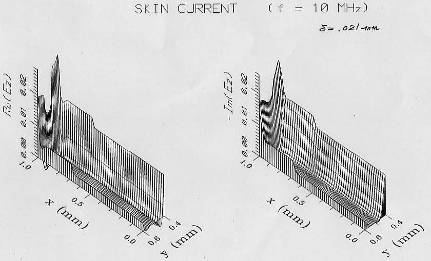
35 Current Distribution vs. Frequency 35
36 Internal inductance Three-conductor Example 8,4, 8,4, 36
37 Surface Roughness 37
38 Surface Roughness alters Rs The formulae presented assumes a perfectly smooth surface The copper must be rough so it will adhere to the laminate Surface roughness can increase the calculated resistance 10-50% as well as frequency dependence proportions Increase the effective path length and decreases the area Tooth height is typically m in RMS value, peak with 11 m. Trace Skin-Depth Tooth structure (4-7 microns) Plane 38
39 Frequency Dependence Surface roughness is not a significant factor until skin depth approaches the tooth size (typically 100 MHz 300 MHz) At high freq., loss becomes unpredictable from regular geometric object because of heavy dependence on a random tooth structure. No longer varies with the root of freq. something else Measurement S 1 P P 1 P( f) P( f) 0log ; : received power : injected power 1 39

40 Example of Surface Roughness Measurements indicate that the surface roughness may cause the AC resistance to deviate from f 0.5 PCB Modeling Tooth Structure PCB X-section POOL Stackup PCB Performance right turns do not equal a right and a left. Fiberglass Bundles 40
41 Hammerstad Model [1980] Rac KHRs f ; measurement Hammerstad h RMS hrms 1.m Hammerstad coeff.: K H 1 h RMS 1 tan Skin-effect R & L R H ( f) KHRs f if t Rdc if t hrms 5.8m RH ( f) if t f LH ( f ) Lext RH( f t) if t f t 41

42 Hammerstad model breaks down in case of very rough copper foil. Other models needed. Surface Profile Measurement 4

43 Hemispherical Model The rough surface is characterized as random protrusions. Assume a TEM incident on the hemisphere at a grazing angle. Calculate total cross section tot of a sphere, then divide it by two gives power loss of hemisphere. Power loss absorbed by flat conducting plane is also considered. K hemi 1 1 tot A base 1 ; 4 Atile Atile f ( kr, r) tot 43
44 Implementation for Rough Surface Prolate spheroid model Surface model 1 r 3 e htooth bbase A A base tile d 1 b peaks base 44
![Huray Model [009] K Huary N 1 n 1 4 tot 1 ; A tile Fig. 5-3 N is determined s.t. total surface area equals that of the hemispheroid constructed before.](/docs-images/83/87254981/images/45-0.jpg "1 bbaseh tooth sin 1 Alat ; 1 bbase htooth Alat N ; a sphere radius, e.g., 0.8m 4 a 45")
45 Huray Model [009] K Huary N 1 n 1 4 tot 1 ; A tile Fig. 5-3 N is determined s.t. total surface area equals that of the hemispheroid constructed before. 1 bbaseh tooth sin 1 Alat ; 1 bbase htooth Alat N ; a sphere radius, e.g., 0.8m 4 a 45
46 Results & Comparisons Huray model predicts I.L. with error < 1.5dB up to 30GHz. Hammerstad model saturates at, not enough loss for rough copper. It should be used only for h RMS < m Hemisphere model overpredicts loss at middle freq. and slightly under-predicts at high freq. Fig
47 Did You Learn How to incorporate loss into tx-line model? How conductor loss will affect propagation constant and attenuation of tx-lines? How to calculate dc and skin-effect resistance for microstrip and striplines? How to describe change in em-field of tx-line due to conductor finite conductivity? How to model tx-line resistance due to conductor surface roughness? Can you distinguish Hammerstad and Huray model? 47
48 Further Reading -1 W. T. Weeks, L. L. Wu, M. F. McAllister, and A. Singh, Resistive and inductive skin effect in rectangular conductors, IBM J. Res. Develop., vol. 3, pp , Nov and J. C. Yang, Boundary integral equation formulation of skin effect problems in multiconductor transmission lines, IEEE Trans. Magn., vol. 5, pp , July A. J. Gruodis and C. S. Chang, Coupled lossy transmission line characterization and simulation, IBM J. Res. Develop., vol. 5, pp. 5-41, Jan R. Ding, L. Tsang, and H. Braunisch, Random rough surface effects in interconnects studied by small perturbation theory in waveguide model, Proc. IEEE EPEPS, 011, pp R. Ding, L. Tsang, and H. Braunisch, "Wave propagation in a randomly rough parallel plate waveguide," IEEE T-MTT, May
49 Further Reading - X. C. Guo, et al., "An analysis of conductor surface roughness effects on signal propagation for stripline interconnects, T-EMC, pp , Jun B. Curran, et al., "On the modeling, characterization, and analysis of the current distribution in PCB transmission lines with surface finishes, T-MTT, pp , Aug M. Y. Koledintseva, et al., "Method of effective roughness dielectric in a PCB: measurement and full-wave simulation verification, T-EMC, pp , Aug F. Bertazzi, et al., "Modeling the conductor losses of thick multiconductor coplanar waveguides and striplines: A conformal mapping approach," T-MTT, pp , April 016. A. V. Rakov, et al., "Quantification of conductor surface roughness profiles in printed circuit boards," T-EMC, pp , Apr
ECE 6340 Intermediate EM Waves. Fall 2016 Prof. David R. Jackson Dept. of ECE. Notes 15
 ECE 634 Intermediate EM Waves Fall 6 Prof. David R. Jackson Dept. of ECE Notes 5 Attenuation Formula Waveguiding system (WG or TL): S z Waveguiding system Exyz (,, ) = E( xye, ) = E( xye, ) e γz jβz αz
ECE 451 Advanced Microwave Measurements. TL Characterization
 ECE 451 Advanced Microwave Measurements TL Characterization Jose E. Schutt-Aine Electrical & Computer Engineering University of Illinois jesa@illinois.edu ECE 451 Jose Schutt-Aine 1 Maxwell s Equations
Compact Equivalent Circuit Models for the Skin Effect
 Microelectromagnetic Devices Group The University of Texas at Austin Compact Equivalent Circuit Models for the Skin Effect Sangwoo Kim, Beom-Taek Lee, and Dean P. Neikirk Department of Electrical and Computer
EELE 3332 Electromagnetic II Chapter 11. Transmission Lines. Islamic University of Gaza Electrical Engineering Department Dr.
 EEE 333 Electromagnetic II Chapter 11 Transmission ines Islamic University of Gaza Electrical Engineering Department Dr. Talal Skaik 1 1 11.1 Introduction Wave propagation in unbounded media is used in
Modeling frequency-dependent conductor losses and dispersion in serial data channel interconnects
 Modeling frequency-dependent conductor losses and dispersion in serial data channel interconnects Yuriy Shlepnev Simberian Inc., www.simberian.com Abstract: Models of transmission lines and transitions
Transmission Line Basics
 Transmission Line Basics Prof. Tzong-Lin Wu NTUEE 1 Outlines Transmission Lines in Planar structure. Key Parameters for Transmission Lines. Transmission Line Equations. Analysis Approach for Z and T d
Electromagnetic Waves
 Electromagnetic Waves Maxwell s equations predict the propagation of electromagnetic energy away from time-varying sources (current and charge) in the form of waves. Consider a linear, homogeneous, isotropic
ECE 497 JS Lecture -03 Transmission Lines
 ECE 497 JS Lecture -03 Transmission Lines Spring 2004 Jose E. Schutt-Aine Electrical & Computer Engineering University of Illinois jose@emlab.uiuc.edu 1 MAXWELL S EQUATIONS B E = t Faraday s Law of Induction
Accounting for High Frequency Transmission Line Loss Effects in HFSS. Andrew Byers Tektronix
 Accounting for High Frequency Transmission Line Loss Effects in HFSS Andrew Byers Tektronix Transmission Line Refresher γ = α + j β = (R + jωl) * (G + jωc) Zo = Zr + j Zi = (R + jωl) / (G + jωc) Transmission
A New, Accurate Quasi-Static Model for Conductor Loss in Coplanar Waveguide
 A New, Accurate Quasi-Static Model for Conductor Loss in Coplanar Waveguide M. S. Islam, E. Tuncer, D. P. Neikirk Dept. of Electrical & Computer Engineering Austin, Texas Conductor loss calculation techniques
Dielectric and Conductor Roughness Models Identification for Successful PCB and Packaging Interconnect Design up to 50 GHz
 Dielectric and Conductor Roughness Models Identification for Successful PCB and Packaging Interconnect Design up to 50 GHz Yuriy Shlepnev Simberian Inc. Abstract: Meaningful interconnect design and compliance
Analytic Solutions for Periodically Loaded Transmission Line Modeling
 Analytic Solutions for Periodically Loaded Transmission Line Modeling Paul G. Huray, huray@sc.edu Priya Pathmanathan, Intel priyap@qti.qualcomm.com Steve Pytel, Intel steve.pytel@ansys.com April 4, 2014
and Ee = E ; 0 they are separated by a dielectric material having u = io-s S/m, µ, = µ, 0
 602 CHAPTER 11 TRANSMISSION LINES 11.10 Two identical pulses each of magnitude 12 V and width 2 µs are incident at t = 0 on a lossless transmission line of length 400 m terminated with a load. If the two
Kimmo Silvonen, Transmission lines, ver
 Kimmo Silvonen, Transmission lines, ver. 13.10.2008 1 1 Basic Theory The increasing operating and clock frequencies require transmission line theory to be considered more and more often! 1.1 Some practical
Boundary and Excitation Training February 2003
 Boundary and Excitation Training February 2003 1 Why are They Critical? For most practical problems, the solution to Maxwell s equations requires a rigorous matrix approach such as the Finite Element Method
A Method to Extract Dielectric Parameters from Transmission Lines with Conductor Surface Roughness at Microwave Frequencies
 Progress In Electromagnetics Research M, Vol. 48, 1 8, 2016 A Method to Extract Dielectric Parameters from Transmission Lines with Conductor Surface Roughness at Microwave Frequencies Binke Huang * and
TC 412 Microwave Communications. Lecture 6 Transmission lines problems and microstrip lines
 TC 412 Microwave Communications Lecture 6 Transmission lines problems and microstrip lines RS 1 Review Input impedance for finite length line Quarter wavelength line Half wavelength line Smith chart A
Microwave Engineering 3e Author - D. Pozar
 Microwave Engineering 3e Author - D. Pozar Sections 3.6 3.8 Presented by Alex Higgins 1 Outline Section 3.6 Surface Waves on a Grounded Dielectric Slab Section 3.7 Stripline Section 3.8 Microstrip An Investigation
EFFECTIVE ROUGHNESS DIELECTRIC TO REPRESENT COPPER FOIL ROUGHNESS IN PRINTED CIRCUIT BOARDS 14-TH4
 EFFECTIVE ROUGHNESS DIELECTRIC TO REPRESENT COPPER FOIL ROUGHNESS IN PRINTED CIRCUIT BOARDS 14-TH4 Marina Koledintseva (Oracle), Oleg Kashurkin (Missouri S&T), Tracey Vincent (CST of America), and Scott
How Interconnects Work: Modeling Conductor Loss and Dispersion
 How Interconnects Work: Modeling Conductor Loss and Dispersion Yuriy Shlepnev SIMBERIAN Inc., www.simberian.com Abstract: Models of transmission lines and transitions accurate over 5-6 frequency decades
INTRODUCTION TO TRANSMISSION LINES DR. FARID FARAHMAND FALL 2012
 INTRODUCTION TO TRANSMISSION LINES DR. FARID FARAHMAND FALL 2012 http://www.empowermentresources.com/stop_cointelpro/electromagnetic_warfare.htm RF Design In RF circuits RF energy has to be transported
ECE 598 JS Lecture 07 Nonideal Conductors and Dielectrics
 ECE 598 JS Lecture 07 Nonideal Conductors and Dielectrics Spring 2012 Jose E. Schutt-Aine Electrical & Computer Engineering University of Illinois jesa@illinois.edu 1 μh E = t ε E H = J + t Material Medium
Roughness Characterization for Interconnect Analysis
 Roughness Characterization for Interconnect Analysis Y. Shlepnev, Simberian Inc. C. Nwachukwu, Isola Group USA 1 Property rights disclosure Copyright 2011 by Simberian Inc., All rights reserved. THIS DOCUMENT
Efficient Calculation of Surface Impedance for Rectangular Conductors. Emre Tuncer and Dean P. Neikirk
 Efficient Calculation of Surface Impedance for Rectangular Conductors Emre Tuncer and Dean P. Neikirk Electrical and Computer Engineering Department University of Texas at Austin Austin, Texas 78712 Abstract
Transmission Line Basics II - Class 6
 Transmission Line Basics II - Class 6 Prerequisite Reading assignment: CH2 Acknowledgements: Intel Bus Boot Camp: Michael Leddige Agenda 2 The Transmission Line Concept Transmission line equivalent circuits
TECHNO INDIA BATANAGAR
 TECHNO INDIA BATANAGAR ( DEPARTMENT OF ELECTRONICS & COMMUNICATION ENGINEERING) QUESTION BANK- 2018 1.Vector Calculus Assistant Professor 9432183958.mukherjee@tib.edu.in 1. When the operator operates on
Chapter 2 Effective Internal Impedance
 Chapter 2 Effective Internal Impedance The impedance boundary condition (IBC) is widely used in scattering problems, eddy current problems, lossy transmission line problems, etc. The IBC is adopted to
Broadband material model identification with GMS-parameters
 Broadband material model identification with GMS-parameters Yuriy Olegovich Shlepnev Simberian Inc. shlepnev@simberian.com 2015 EPEPS Conference, October 27, 2015 2015 Simberian Inc. Outline Introduction
An improved planar cavity model for dielectric characterization
 Scholars' Mine Masters Theses Student Research & Creative Works Fall 2015 An improved planar cavity model for dielectric characterization Benjamin Jay Conley Follow this and additional works at: http://scholarsmine.mst.edu/masters_theses
Understanding EMC Basics
 1of 7 series Webinar #1 of 3, February 27, 2013 EM field theory, and 3 types of EM analysis Webinar Sponsored by: EurIng CEng, FIET, Senior MIEEE, ACGI AR provides EMC solutions with our high power RF/Microwave
Transmission Line Model for Rectangular Waveguides accurately incorporating Loss Effects
 Transmission Line Model for Rectangular Waveguides accurately incorporating Loss Effects Konstantin Lomakin konstantin.lomakin@fau.de Institute of Microwaves and Photonics Friedrich-Alexander-Universität
Roughness Characterization for Interconnect Analysis
 Roughness Characterization for Interconnect Analysis Yuriy Shlepnev #, Chudy Nwachukwu * # Simberian Inc. * Isola Abstract A novel method for practical prediction of interconnect conductor surface roughness
Chap. 1 Fundamental Concepts
 NE 2 Chap. 1 Fundamental Concepts Important Laws in Electromagnetics Coulomb s Law (1785) Gauss s Law (1839) Ampere s Law (1827) Ohm s Law (1827) Kirchhoff s Law (1845) Biot-Savart Law (1820) Faradays
Signal integrity simulation strategies for accurate and fast results Correct Material Properties that simulate quickly.
 Signal integrity simulation strategies for accurate and fast results Correct Material Properties that simulate quickly Tracey Vincent Loss Components Mismatch Conductor Loss Radiative Dielectric Coupling
ELECTROMANETIC PULSE PROPAGATION IN A COAXIAL CABLE
 ELECTROMANETIC PULSE PROPAGATION IN A COAXIAL CABLE The mechanical waves on a stretched string are easily generated and observed but not easily studied in quantitative detail. The propagating waves in
ECEN720: High-Speed Links Circuits and Systems Spring 2017
 ECEN70: High-Speed Links Circuits and Systems Spring 07 Lecture : Channel Components, Wires, & Transmission Lines Sam Palermo Analog & Mixed-Signal Center Texas A&M University Announcements Lab Lab begins
6-1 Chapter 6 Transmission Lines
 6-1 Chapter 6 Transmission ines ECE 3317 Dr. Stuart A. ong 6-2 General Definitions p.133 6-3 Voltage V( z) = α E ds ( C z) 1 C t t ( a) Current I( z) = α H ds ( C0 closed) 2 C 0 ( b) http://www.cartoonstock.com
PHY3128 / PHYM203 (Electronics / Instrumentation) Transmission Lines
 Transmission Lines") Transmission Lines Introduction A transmission line guides energy from one place to another. Optical fibres, waveguides, telephone lines and power cables are all electromagnetic transmission lines. are
Transmission Lines Introduction A transmission line guides energy from one place to another. Optical fibres, waveguides, telephone lines and power cables are all electromagnetic transmission lines. are
Transmission Lines. Plane wave propagating in air Y unguided wave propagation. Transmission lines / waveguides Y. guided wave propagation
 Transmission Lines Transmission lines and waveguides may be defined as devices used to guide energy from one point to another (from a source to a load). Transmission lines can consist of a set of conductors,
Lecture Outline 9/27/2017. EE 4347 Applied Electromagnetics. Topic 4a
 9/7/17 Course Instructor Dr. Raymond C. Rumpf Office: A 337 Phone: (915) 747 6958 E Mail: rcrumpf@utep.edu EE 4347 Applied Electromagnetics Topic 4a Transmission Lines Transmission These Lines notes may
Broadband transmission line models for analysis of serial data channel interconnects
 PCB Design Conference East, Durham NC, October 23, 2007 Broadband transmission line models for analysis of serial data channel interconnects Y. O. Shlepnev, Simberian, Inc. shlepnev@simberian.com Simberian:
xˆ z ˆ. A second vector is given by B 2xˆ yˆ 2z ˆ.
 Directions for all homework submissions Submit your work on plain-white or engineering paper (not lined notebook paper). Write each problem statement above each solution. Report answers using decimals
CHAPTER 9 ELECTROMAGNETIC WAVES
 CHAPTER 9 ELECTROMAGNETIC WAVES Outlines 1. Waves in one dimension 2. Electromagnetic Waves in Vacuum 3. Electromagnetic waves in Matter 4. Absorption and Dispersion 5. Guided Waves 2 Skip 9.1.1 and 9.1.2
Topic 5: Transmission Lines
 Topic 5: Transmission Lines Profs. Javier Ramos & Eduardo Morgado Academic year.13-.14 Concepts in this Chapter Mathematical Propagation Model for a guided transmission line Primary Parameters Secondary
EECS 117 Lecture 3: Transmission Line Junctions / Time Harmonic Excitation
 EECS 117 Lecture 3: Transmission Line Junctions / Time Harmonic Excitation Prof. Niknejad University of California, Berkeley University of California, Berkeley EECS 117 Lecture 3 p. 1/23 Transmission Line
1300 (W/m 2 ) (V/cm) = 275 (V/m) (A/cm) = (A/m). E = 990 (V/m), H = 2.63 (A/m).
 (V/cm) = 275 (V/m) (A/cm) = (A/m). E = 990 (V/m), H = 2.63 (A/m).") Homework #4 P8-16 There is a continuing discuss on radiation hazards to human health The following calculations will provide a rough comparison a) The US standard for personal safet in a microwe environment
Homework #4 P8-16 There is a continuing discuss on radiation hazards to human health The following calculations will provide a rough comparison a) The US standard for personal safet in a microwe environment
Characterizing Geometry- Dependent Crossover Frequency for Stripline Dielectric and Metal Losses
 DesignCon 2016 Characterizing Geometry- Dependent Crossover Frequency for Stripline Dielectric and Metal Losses Svetlana C. Sejas-García Chudy Nwachukwu Isola 1 Abstract Digital signaling requires interconnects
Elimination of Conductor Foil Roughness Effects in Characterization of Dielectric Properties of Printed Circuit Boards 14 TH1
 Elimination of Conductor Foil Roughness Effects in Characterization of Dielectric Properties of Printed Circuit Boards 14 TH1 Marina Koledintseva, Aleksei Rakov, Alexei Koledintsev, James Drewniak (Missouri
Your RF Cable, the unknown Entity
 HAM RADIO 2018 Your RF Cable, the unknown Entity PROF. DR. THOMAS BAIER E-mail: baier@hs-ulm.de DG8SAQ Hochschule Ulm University of Applied Sciences Prittwitzstrasse 10 89075 Ulm Thanks to: Dan Maguire
CONTROL OF MICROWAVE HEATING IN RECTANGULAR WAVEGUIDE
 ISTP-16, 2005, PRAGUE 16 TH INTERNATIONAL SYMPOSIUM ON TRANSPORT PHENOMENA CONTROL OF MICROWAVE HEATING IN RECTANGULAR WAVEGUIDE Kazuo AOKI*, Masatoshi AKAHORI*, Kenji OSHIMA** and Masato MORITA* *Nagaoka
Inductance and Partial Inductance What's it all mean?
 Inductance and Partial Inductance What's it all mean? Bruce Archambeault, PhD IEEE Fellow, IBM Distinguished Engineer Bruce.arch@ieee.org Inductance Probably the most misunderstood concept in electrical
Analysis of Characteristics of Coplanar Waveguide with Finite Ground-planes by the Method of Lines
 PIERS ONLINE, VOL. 6, NO. 1, 21 46 Analysis of Characteristics of Coplanar Waveguide with Finite Ground-planes by the Method of Lines Min Wang, Bo Gao, Yu Tian, and Ling Tong College of Automation Engineering,
Which one is better? Comparing Options to Describe Frequency Dependent Losses
 DesignCon 2013 Which one is better? Comparing Options to Describe Frequency Dependent Losses Dr. Eric Bogatin, Bogatin Enterprises eric@bethesignal.com Dr. Don DeGroot, CCN & Andrews University don@ccnlabs.com
UNIT I ELECTROSTATIC FIELDS
 UNIT I ELECTROSTATIC FIELDS 1) Define electric potential and potential difference. 2) Name few applications of gauss law in electrostatics. 3) State point form of Ohm s Law. 4) State Divergence Theorem.
Introduction to RF Design. RF Electronics Spring, 2016 Robert R. Krchnavek Rowan University
 Introduction to RF Design RF Electronics Spring, 2016 Robert R. Krchnavek Rowan University Objectives Understand why RF design is different from lowfrequency design. Develop RF models of passive components.
Plane Waves GATE Problems (Part I)
") Plane Waves GATE Problems (Part I). A plane electromagnetic wave traveling along the + z direction, has its electric field given by E x = cos(ωt) and E y = cos(ω + 90 0 ) the wave is (a) linearly polarized
Plane Waves GATE Problems (Part I). A plane electromagnetic wave traveling along the + z direction, has its electric field given by E x = cos(ωt) and E y = cos(ω + 90 0 ) the wave is (a) linearly polarized
Leakage and ohmic losses investigation in substrate-integrated waveguide
 RADIO SCIENCE, VOL. 42,, doi:10.1029/2007rs003621, 2007 Leakage and ohmic losses investigation in substrate-integrated waveguide Wenquan Che, 1 Dapeng Wang, 1 Kuan Deng, 1 and Y. L. Chow 2 Received 6 January
AC Circuits. The Capacitor
 The Capacitor Two conductors in close proximity (and electrically isolated from one another) form a capacitor. An electric field is produced by charge differences between the conductors. The capacitance
STUDY OF LOSS EFFECT OF TRANSMISSION LINES AND VALIDITY OF A SPICE MODEL IN ELECTROMAG- NETIC TOPOLOGY
 Progress In Electromagnetics Research, PIER 90, 89 103, 2009 STUDY OF LOSS EFFECT OF TRANSMISSION LINES AND VALIDITY OF A SPICE MODEL IN ELECTROMAG- NETIC TOPOLOGY H. Xie, J. Wang, R. Fan, andy. Liu Department
Dk & Df ALGEBRAIC MODEL v2.04 (NOTE: only change from v2.03 is correction of Cu conductivity used in surface roughness [Hurray model] calculation)
![Dk & Df ALGEBRAIC MODEL v2.04 (NOTE: only change from v2.03 is correction of Cu conductivity used in surface roughness [Hurray model] calculation)](/thumbs/82/85653625.jpg "Dk & Df ALGEBRAIC MODEL v2.04 (NOTE: only change from v2.03 is correction of Cu conductivity used in surface roughness [Hurray model] calculation)") Joel Goergen Beth (Donnay) Kochuparambil Cisco Systems Inc. 5 January, 03 Dk & Df AGEBRAIC MODE v.04 (NOTE: only change from v.03 is correction of Cu conductivity used in surface roughness [Hurray model]
Joel Goergen Beth (Donnay) Kochuparambil Cisco Systems Inc. 5 January, 03 Dk & Df AGEBRAIC MODE v.04 (NOTE: only change from v.03 is correction of Cu conductivity used in surface roughness [Hurray model]
Graduate Diploma in Engineering Circuits and waves
 9210-112 Graduate Diploma in Engineering Circuits and waves You should have the following for this examination one answer book non-programmable calculator pen, pencil, ruler No additional data is attached
General Appendix A Transmission Line Resonance due to Reflections (1-D Cavity Resonances)
") A 1 General Appendix A Transmission Line Resonance due to Reflections (1-D Cavity Resonances) 1. Waves Propagating on a Transmission Line General A transmission line is a 1-dimensional medium which can
A 1 General Appendix A Transmission Line Resonance due to Reflections (1-D Cavity Resonances) 1. Waves Propagating on a Transmission Line General A transmission line is a 1-dimensional medium which can
Microwave Network Analysis
 Prof. Dr. Mohammad Tariqul Islam titareq@gmail.my tariqul@ukm.edu.my Microwave Network Analysis 1 Text Book D.M. Pozar, Microwave engineering, 3 rd edition, 2005 by John-Wiley & Sons. Fawwaz T. ILABY,
Introduction. Concept of shielding
 Shielding Introduction Concept of shielding Shielding of a metal shield (theory) For E field SE.. 2log E E i t For H field SE.. 2log H H i t Do they be equal? Shielding of a metal shield (theory) It depends.
Transmission-Line Essentials for Digital Electronics
 C H A P T E R 6 Transmission-Line Essentials for Digital Electronics In Chapter 3 we alluded to the fact that lumped circuit theory is based on lowfrequency approximations resulting from the neglect of
Omar M. Ramahi University of Waterloo Waterloo, Ontario, Canada
 Omar M. Ramahi University of Waterloo Waterloo, Ontario, Canada Traditional Material!! Electromagnetic Wave ε, μ r r The only properties an electromagnetic wave sees: 1. Electric permittivity, ε 2. Magnetic
COURTESY IARE. Code No: R R09 Set No. 2
 Code No: R09220404 R09 Set No. 2 II B.Tech II Semester Examinations,APRIL 2011 ELECTRO MAGNETIC THEORY AND TRANSMISSION LINES Common to Electronics And Telematics, Electronics And Communication Engineering,
Non-Sinusoidal Waves on (Mostly Lossless)Transmission Lines
Transmission Lines") Non-Sinusoidal Waves on (Mostly Lossless)Transmission Lines Don Estreich Salazar 21C Adjunct Professor Engineering Science October 212 https://www.iol.unh.edu/services/testing/sas/tools.php 1 Outline of
Non-Sinusoidal Waves on (Mostly Lossless)Transmission Lines Don Estreich Salazar 21C Adjunct Professor Engineering Science October 212 https://www.iol.unh.edu/services/testing/sas/tools.php 1 Outline of
Electricity & Magnetism Study Questions for the Spring 2018 Department Exam December 4, 2017
 Electricity & Magnetism Study Questions for the Spring 2018 Department Exam December 4, 2017 1. a. Find the capacitance of a spherical capacitor with inner radius l i and outer radius l 0 filled with dielectric
EMC Considerations for DC Power Design
 EMC Considerations for DC Power Design Tzong-Lin Wu, Ph.D. Department of Electrical Engineering National Sun Yat-sen University Power Bus Noise below 5MHz 1 Power Bus Noise below 5MHz (Solution) Add Bulk
DesignCon A Causal Huray Model for Surface Roughness. J. Eric Bracken, ANSYS Inc.
 DesignCon 2012 A Causal Huray Model for Surface Roughness J. Eric Bracken, ANSYS Inc. Abstract The recently proposed Huray model is very accurate for modeling surface roughness. It can be used to modify
DesignCon Effect of conductor profile on the insertion loss, phase constant, and dispersion in thin high frequency transmission lines
 DesignCon 2010 Effect of conductor profile on the insertion loss, phase constant, and dispersion in thin high frequency transmission lines Allen F. Horn III, Rogers Corporation Al.horn@rogerscorp.com,
Microwave Characterization of Electrical Conductivity of Composite Conductors by Half-Wavelength Coplanar Resonator
 Progress In Electromagnetics Research Letters, Vol. 60, 73 80, 2016 Microwave Characterization of Electrical Conductivity of Composite Conductors by Half-Wavelength Coplanar Resonator Bilal Benarabi 1,
Causal Modeling and Extraction of Dielectric Constant and Loss Tangent for Thin Dielectrics
 Causal Modeling and Extraction of Dielectric Constant and Loss Tangent for Thin Dielectrics A. Ege Engin 1, Abdemanaf Tambawala 1, Madhavan Swaminathan 1, Swapan Bhattacharya 1, Pranabes Pramanik 2, Kazuhiro
ANTENNAS and MICROWAVES ENGINEERING (650427)
") Philadelphia University Faculty of Engineering Communication and Electronics Engineering ANTENNAS and MICROWAVES ENGINEERING (65427) Part 2 Dr. Omar R Daoud 1 General Considerations It is a two-port network
Philadelphia University Faculty of Engineering Communication and Electronics Engineering ANTENNAS and MICROWAVES ENGINEERING (65427) Part 2 Dr. Omar R Daoud 1 General Considerations It is a two-port network
November MVP R&S FSW Analyzer. Vol. 54 No. 11. Founded in mwjournal.com
 Vol. 54 No. 11 November 211 MVP R&S FSW Analyzer Founded in 1958 mwjournal.com Improved Thermal Management of Microwave PCBs Using Advanced Circuit Materials Thermal management in microwave printed-circuit
Effects from the Thin Metallic Substrate Sandwiched in Planar Multilayer Microstrip Lines
 Progress In Electromagnetics Research Symposium 2006, Cambridge, USA, March 26-29 115 Effects from the Thin Metallic Substrate Sandwiched in Planar Multilayer Microstrip Lines L. Zhang and J. M. Song Iowa
DESIGN AND OPTIMIZATION OF EQUAL SPLIT BROADBAND MICROSTRIP WILKINSON POWER DI- VIDER USING ENHANCED PARTICLE SWARM OPTI- MIZATION ALGORITHM
 Progress In Electromagnetics Research, Vol. 118, 321 334, 2011 DESIGN AND OPTIMIZATION OF EQUAL SPLIT BROADBAND MICROSTRIP WILKINSON POWER DI- VIDER USING ENHANCED PARTICLE SWARM OPTI- MIZATION ALGORITHM
Chapter 9. Electromagnetic waves
 Chapter 9. lectromagnetic waves 9.1.1 The (classical or Mechanical) waves equation Given the initial shape of the string, what is the subsequent form, The displacement at point z, at the later time t,
Chapter 3. Conductor loss calculation constitutes a major part of lossy transmission line
 Chapter 3 Eective Internal Impedance Conductor loss calculation constitutes a major part of lossy transmission line analysis. High-speed digital interconnects can be considered as transmission lines. Knowledge
Module 2 : Transmission Lines. Lecture 1 : Transmission Lines in Practice. Objectives. In this course you will learn the following
 Objectives In this course you will learn the following Point 1 Point 2 Point 3 Point 4 Point 5 Point 6 Point 7 Point 8 Point 9 Point 10 Point 11 Point 12 Various Types Of Transmission Line Explanation:
Chapter 3 Conformal Mapping Technique
 Chapter 3 Conformal Mapping Technique Various techniques have been used to calculate the conductor loss, including Wheeler's incremental inductance rule [26], closed-form formulae based on rigorous numerical
KINGS COLLEGE OF ENGINEERING DEPARTMENT OF ELECTRONICS AND COMMUNICATION ENGINEERING QUESTION BANK
 KINGS COLLEGE OF ENGINEERING DEPARTMENT OF ELECTRONICS AND COMMUNICATION ENGINEERING QUESTION BANK SUB.NAME : ELECTROMAGNETIC FIELDS SUBJECT CODE : EC 2253 YEAR / SEMESTER : II / IV UNIT- I - STATIC ELECTRIC
Analytical Extraction of Via Near-Field Coupling Using a Multiple Scattering Approach
 Analytical Extraction of Via Near-Field Coupling Using a Multiple Scattering Approach 17 th IEEE Workshop on Signal and Power Integrity May 12-15, 213 Paris, France Sebastian Müller 1, Andreas Hardock
ECE357H1F ELECTROMAGNETIC FIELDS FINAL EXAM. 28 April Examiner: Prof. Sean V. Hum. Duration: hours
 UNIVERSITY OF TORONTO FACULTY OF APPLIED SCIENCE AND ENGINEERING The Edward S. Rogers Sr. Department of Electrical and Computer Engineering ECE357H1F ELECTROMAGNETIC FIELDS FINAL EXAM 28 April 15 Examiner:
Inductors. Hydraulic analogy Duality with capacitor Charging and discharging. Lecture 12: Inductors
 Lecture 12: nductors nductors Hydraulic analogy Duality with capacitor Charging and discharging Robert R. McLeod, University of Colorado http://hilaroad.com/camp/projects/magnet.html 99 Lecture 12: nductors
Guided Waves. Daniel S. Weile. Department of Electrical and Computer Engineering University of Delaware. ELEG 648 Guided Waves
 Guided Waves Daniel S. Weile Department of Electrical and Computer Engineering University of Delaware ELEG 648 Guided Waves Outline Outline The Circuit Model of Transmission Lines R + jωl I(z + z) I(z)
Spectral Domain Analysis of Open Planar Transmission Lines
 Mikrotalasna revija Novembar 4. Spectral Domain Analysis of Open Planar Transmission Lines Ján Zehentner, Jan Mrkvica, Jan Macháč Abstract The paper presents a new code calculating the basic characteristics
A Review of Basic Electromagnetic Theories
 A Review of Basic Electromagnetic Theories Important Laws in Electromagnetics Coulomb s Law (1785) Gauss s Law (1839) Ampere s Law (1827) Ohm s Law (1827) Kirchhoff s Law (1845) Biot-Savart Law (1820)
Electromagnetic Waves
 Electromagnetic Waves Our discussion on dynamic electromagnetic field is incomplete. I H E An AC current induces a magnetic field, which is also AC and thus induces an AC electric field. H dl Edl J ds
Transmission-Reflection Method to Estimate Permittivity of Polymer
 Transmission-Reflection Method to Estimate Permittivity of Polymer Chanchal Yadav Department of Physics & Electronics, Rajdhani College, University of Delhi, Delhi, India Abstract In transmission-reflection
APPLICATIONS OF GAUSS S LAW
 APPLICATIONS OF GAUSS S LAW Although Gauss s Law is always correct it is generally only useful in cases with strong symmetries. The basic problem is that it gives the integral of E rather than E itself.
ECE Spring Prof. David R. Jackson ECE Dept. Notes 6
 ECE 6341 Spring 2016 Prof. David R. Jackson ECE Dept. Notes 6 1 Leaky Modes v TM 1 Mode SW 1 v= utan u ε R 2 R kh 0 n1 r = ( ) 1 u Splitting point ISW f = f s f > f s We will examine the solutions as the
Transmission Lines. Transmission lines. Telegraphist Equations. Reflection Coefficient. Transformation of voltage, current and impedance
 Transmission Lines Transmission lines Telegraphist Equations Reflection Coefficient Transformation of voltage, current and impedance Application of trasnmission lines 1 ENGN4545/ENGN6545: Radiofrequency
SKIN EFFECT : ELECTROMAGNETIC WAVE OR DIFFUSION?
 SKIN EFFECT : ELECTROMAGNETIC WAVE OR DIFFUSION? At high frequencies current in a conductor flows mainly on its surface, and this is known as the skin effect. Two possible mechanisms are given in the published
Magnetic Force on a Moving Charge
 Magnetic Force on a Moving Charge Electric charges moving in a magnetic field experience a force due to the magnetic field. Given a charge Q moving with velocity u in a magnetic flux density B, the vector
INSTITUTE OF AERONAUTICAL ENGINEERING Dundigal, Hyderabad Electronics and Communicaton Engineering
 INSTITUTE OF AERONAUTICAL ENGINEERING Dundigal, Hyderabad - 00 04 Electronics and Communicaton Engineering Question Bank Course Name : Electromagnetic Theory and Transmission Lines (EMTL) Course Code :
Uniform Plane Waves Page 1. Uniform Plane Waves. 1 The Helmholtz Wave Equation
 Uniform Plane Waves Page 1 Uniform Plane Waves 1 The Helmholtz Wave Equation Let s rewrite Maxwell s equations in terms of E and H exclusively. Let s assume the medium is lossless (σ = 0). Let s also assume
ESE 570: Digital Integrated Circuits and VLSI Fundamentals
 ESE 570: Digital Integrated Circuits and VLSI Fundamentals Lec 24: April 19, 2018 Crosstalk and Wiring, Transmission Lines Lecture Outline! Crosstalk! Repeaters in Wiring! Transmission Lines " Where transmission
Effective Conductivity Concept for Modeling Conductor Surface Roughness G. Gold, K. Helmreich Institute of Microwaves and Photonics
 Effective Conductivity Concept for Modeling Conductor Surface Roughness Institute of Microwaves and Photonics Friedrich-Alexander-University Erlangen-Nuremberg gerald.gold@fau.de klaus.helmreich@fau.de