Energy level diagram for the p n junction in thermal equilibrium Electric field
|
|
|
- Alberta Byrd
- 5 years ago
- Views:
Transcription

1 pn JUNCTION


2 Energy level diagram for the p n junction in thermal equilibrium Electric field E C E F E V p type Electron Drift Neutral p region Hole Diffusion Diffusion current Drift current Depletion region n type Electron Diffusion Neutral n region Hole Drift ev 0 => built in potential Diffusion current is due the to concentration gradient majority carriers. Drift current is due to electric field at the junction minority carriers. E C E F E V
3 Holes diffuse from the p type into the n type, electrons diffuse from the n type into the p type, creating a diffusion current. Once the holes [electrons] cross into the n type [p type] region, they recombine with the electrons [holes]. This recombination strips the n type [p type] of its electrons near the boundary, creating an electric field due to the positive and negative bound charges. The region stripped of carriers is called the SPACE CHARGE REGION, or depletion region. V 0 is the contact potential that exists due to the electric field. Some carriers are generated (thermally) and make their way into the depletion region where they are whisked away by the electric field, creating a DRIFT CURRENT.
4 In equilibrium, diffusion current is balanced by drift current. Moreover, the built in potential (electric field) stops the diffusion by imposing a larger barrier to holes and electrons. The diffusion current is determined by the # of carriers able to overcome the potential barrier. The drift current is determined by the generation of minority carriers (in the depletion region) which then move due to the E field. This generation is determined by the temperature. At equilibrium, the two components are equal

5 How current flows through the p n junction when a bias (voltage) is applied? Reverse Bias + p n Electrons leave the n side and holes leave the p side depletion region grows V 0 grows and the diffusion current I D decreases Reduced hole diffusion from p side to n side compared with the equilibrium case. Reduced electron diffusion from n side to p side compared with the equilibrium case At equilibrium there is a V R across the terminals greater than V 0 junction potential increased Drift current flow is similar to the equilibrium case (due to generation of e h pairs). Overall a very small reverse saturation current flows.

6 Reverse Bias I (current) V b I 0 applied voltage (V) V b ; Breakdown voltage I 0 ; Reverse saturation current

7 FORWARD BIAS + p n forward bias Junction potential is reduced Enhanced hole diffusion from p side to n side compared with the equilibrium case diffusion current increases Enhanced electron diffusion from n side to p side compared with the equilibrium case diffusion current increases Drift current flow is similar to the equilibrium case. This current is due to the minority carriers on each side of the junction and the movement of minority carriers is due to the built in field accross the depletion region. These injected minorities recombine with majorities.
8 Ideal diode equation Change V with V for reverse bias. When qv >a few kt; exponential term goes to zero I I o qv exp 1 kt I I o Reverse saturation current Current Forward Bias V B =Breakdown voltage I 0 =Reverse saturation current V B I 0 Voltage Reverse Bias
9

10 APPLICATIONS OF THE p n JUNCTION LED= light emitting diode When electrons and holes combine, they release energy. This energy is often released as heat into the lattice, but in some materials, known as direct bandgap materials, they release light. LED are semiconductor p n junctions that under forward bias conditions can emit radiation by electroluminescence in the UV, visible or infrared regions of the electromagnetic spectrum. The quanta of light energy released is approximately proportional to the band gap of the semiconductor.
11 Direct Band Gap Semiconductors The E-k Diagram E k The Energy Band Diagram Conduction Band (CB) E g e - E c Empty k h E c CB e - h Valence Band (VB) h + E v Occupied k E v h + VB k E k curves consists of many points each point corresponding to a possible state, wave function (k) allowed existing in the crystal. The points are so closed that E k is draw as continuous curve.
12 Indirect Band Gap Semiconductors E E E Direct Bandgap E g CB E c E v Photon CB Indirect Bandgap, E g k cb E c E r CB E c Phonon k VB k k VB k vb E v k k VB E v k (a) GaAs (b) Si (c) Si with a recombination center GaAs Min of the CB directly above the Max in the VB direct band gap Si Min of the CB displaced from the Max in the VB indirect band gap Si Recombination of an e and a hole in Si involves a recombination center.
13 Whenever something changes state, one must conserve not only energy, but also momentum. In the direct band gap semiconductors: the transition from CB to VB band involves essentially no change in momentum. Photons, possess a fair amount of energy (several ev/photon in some cases ) but they have very little momentum associated with them. Thus, for a direct band gap material, the excess energy of the e hole recombination can either be taken away as heat, or more likely, as a photon of light. This radiative transition then : conserves energy and momentum by giving off light whenever an electron and hole recombine.
14 LED: Mechanism is injection Electroluminescence Luminescence is the emission of radiation from a solid when the solid is supplied with some form of energy. Luminescence part tells us that we are producing photons. Electroluminescence excitation results from the application of an electric field. Electro part tells us that the photons are being produced by an electric current. Injection tells us that photon production is by the injection of current carriers In a p n junction diode injection electroluminescence occurs resulting in light emission when the junction is forward biased.


15 How does it work? p n forward bias A typical LED needs a p n junction P-n junction Junction is biased to produce even more e h and to inject electrons from n to p for recombination to happen. Recombination produces light!!
16 Notice that: If the e diffusion length is greater than the hole diffusion length, the photon emitting region will be bigger on the p side of the junction than that of the n side. Constructing a real LED may be best to consider a n ++ p structure. It is usual to find the photon emitting volume occurs mostly on one side of the junction region. This applies to LEDs devices as well as solid state LASERs.
17 MATERIALS FOR LEDS The semiconductor bandgap energy defines the energy of the emitted photons in a LED. To fabricate LEDs that can emit photons from the IR to the UV of the e.m. spectrum, then we must consider several different material systems. No single system can span this energy band at present. Questions to ask when choosing the right material: Can it be doped or not? What wavelength it can emit? Would the material able to allow radiative recombiation? Direct or indirect bang gap semiconductor? CB VB
18 Visible light has a wavelength on the order of nanometers. Violet Blue Green Yellow Orange Red ~ 3.17eV ~ 2.73eV ~ 2.52eV ~ 2.15eV ~ 2.08eV ~ 1.62eV hc ( nm) E(eV) 1240 E(eV)
 for each of the different spectral regions.")

 The human eye, of course, is not")
19 The materials which are used for important light emitting diodes (LEDs) for each of the different spectral regions Relative eye response GaN ZnSe GaP:N GaAs.14 p 86 GaAs.35 p 65 GaAs.6 p violet blue green yellow orange red Wavelength (nm) The human eye, of course, is not equally responsive to all colors. Relative response of the human eye to various colors
20 Group III-V LED materials Al Ga In N P As AlN, AlP,AlAs GaN, GaP, GaAs InN, InP, InAs Binary compounds GaAs GaP GaAl GaAsP GaAsAl Ternary compounds By varying x it is possible to control the band gap energy and thereby the emission wavelength over the range of 800 nm to 900 nm. Ex. in GaAs: some of the As can be replaced by P and make a mixed compound semiconductor GaAs 1 x P x so the desired color of LED can be selected simply growing a crystal with the proper P concentration.
21 Blue LEDs Blue LEDs are fabricated using silicon carbide (SiC) and gallium nitride (GaN). Unfortunately both of these materials systems have a low efficiency as an LED material. SiC has an indirect gap, and no magic isoelectronic centre has been found to date. The transitions that give rise to blue photon emission in SiC are between the bands and doping centres in the SiC (Al p type, N n type). GaN is a direct gap semiconductor, but has the major disadvantage that bulk material cannot be made p type. GaN as grown, is naturally n ++. Light emitting structures are made by producing an intrinsic GaN layer using heavy Zn doping. Light emission occurs when electrons are injected from an n + GaN layer into the intrinsic Zn doped region.

22 The Nobel Prize in Physics 2014 was awarded jointly to Isamu Akasaki, Hiroshi Amano and Shuji Nakamura "for the invention of efficient blue light emitting diodes which has enabled bright and energy saving white light sources".
 Efficiency: Diodes emit almost no heat and run at very low amperes.")
23 Advantages of Light Emitting Diodes (LEDs) Longevity: The light emitting element in a diode is a small conductor chip rather than a filament which greatly extends the diode s life in comparison to an incandescent bulb (10 4 hours life time compared to ~10 3 hours for incandescence light bulb) Efficiency: Diodes emit almost no heat and run at very low amperes. Greater Light Intensity: Since each diode emits its own light Low Cost of production Robustness: Solid state component, not as fragile as incandescence light bulb
24 POLYMERS LED made of POLYMERS are possible since some polymers can be n and p type. OLEDs: organic light emitting diode, which have relatively low molecular weight; PLEDs:polymer light emitting diodes high molecular weight. OLEDs/PLEDs have distinct advantages: A wide variety of colors is possible, and more than a single color may be produced from each device it is possible to generate white light. Are easier to fabricate (by printing onto their substrates with an ink jet printer), are relatively inexpensive. OLED displays are currently being used on digital cameras, cell phones, and car audio components. Potential applications include larger displays for televisions, computers, and billboards. In addition, using the right combination of materials, these displays can also be FLEXIBLE. The semiconductor LEDs currently have longer lifetimes than these organic emitters.


25 Construction of the LED OLED The plastic bubble (epoxy lens) helps in directing the light so that it is more effectively seen.

26 Other diode applications If light with photon energy greater than the band gap is applied to a p n junction. Carriers are created by shining light, electrons are dislodged from their covalent bonds and hence electron hole pairs are created. Interesting applications are: Digital cameras, Photodiodes, Photo detectors and Solar cells
27 Photodiodes: Compromise between speed and junction width leads to a p intrisic n junction, where carriers will be rapidly swept across, and can quickly diffuse in the p and n regions. As a result, current flows through the diode that is proportional to the light intensity. A semiconductor


28 Incident Light of energy E>E gap A semiconductor Start with a semiconductor The semiconductor absorbs the incident light from the sun
 that separates the electron and hole and produce an electric current this is the Photovoltaic effect Semiconductor")
29 An electron hole couple is generated upon light irradiation. Both the electron and hole can move to create a photo generated electrical current across the semiconductor. Another semiconductor layer is needed to form a junction (p n) that separates the electron and hole and produce an electric current this is the Photovoltaic effect Semiconductor 2 e - h +
30 A photovoltaic cell works using the reverse process: a photon can create an electron hole couple (light irradiation) across the bandgap. If this happens at a pn junction, the electrons and holes are separated by the potential in the depletion zone to give an electrical current across the semiconductor.
31 e current = metal contacts n type semiconductor p type semiconductor Electrical Power p n junction Photovoltaic energy conversion results from 1) charge generation 2) charge separation 3) charge transport
32 Ideal diode equation I I o qv exp 1 kt I I o Reverse saturation current V B I 0 Reverse Bias + p + + n + + Current Forward Bias V B = Breakdown voltage I 0 = Reverse saturation current Voltage Under reverse bias, the barrier to diffusion is raised and very few carriers can diffuse from one region to another. Diffusion current is usually negligible for reverse bias, the current is due mostly to the drift of minority carriers.

33 The photodiode can operate in photovoltaic mode, that is unbiased and connected to a load impedance but most of the devices are usually reversed biased because this reduces the transit time. + p + + n + +

34 Energy Band diagram for a pn photodiode p Depletion region n Absorptionofaphotonwithhv>E g creates an electron hole pair 1.p type Region High probability that the minority e will diffuse towards the barrier and drift across under the influence of the depletion field adding one charge e to the current, if the e is created within a diffusion length. If not the e is most likely to recombine. 2.n type region As above except now the minority holes diffuse towards the barrier. 3. Depletion region Both carriers are swept out under the influence of the depletion field. They only traverse part of the junction width thus the contributed charge is again 1e.

35 An added generation rate, g op,participatesinthecurrent: g op= optical generation rate AL p g op = Extra holes generated on the n side AL n g op = Extra electrons generated on the p side AWg op = Extra carriers generated within the depletion region. The total reverse current needs to be modified to incorporate the optical generation current: I I o qv exp 1 kt DARK CURRENT (no light) I op qg op A(L p L n W) I I I tot op L
36 I I I I tot op I o qv exp 1 kt UNDER IRRADIATION The I V curve will be lowered proportionally to the generation rate (g) dark current increase the incident power light
37 General characteristics of a photodiode I P 0 P / / q h QUANTUM EFFICIENCY =number of photogenerated electron hole pairs per incident photon: I P = photo generated current by the absorption of incident optical power P opt at a wavelength (corresponding to photon energy h ) I P P 0 q h ( m) 1.24 [A/W] RESPONSIVITY = ratio of the photocurrent to the optical power
38 For a given quantum efficiency the responsivity increases linearly with the wavelength. For an ideal photodiode =1 [A/W] ( m) 1.24 Responsivity vs. wavelength quantum efficiency is also reported
39 General characteristics of a photodiode Optical power absorbed, P(x) in the depletion region can be written in terms of incident optical power, P 0 : P( x) P 0 (1 e ( ) x s ) Absorption coefficient s ( ) strongly depends on wavelength. The upper wavelength cutoff for any semiconductor can be determined by its energy gap as follows: ( m ) c 1.24 E (ev) g
40 General characteristics of a photodiode I P 0 P / q / h one of the key factors that determines the quantum efficiency is the optical absorption coefficient. Since is a strong function of, for a given semiconductor the wavelength range in which appreciable photocurrent can be generated is limited. The long wavelength cut off c is established by the energy gap. The short wavelength cut off comes about because becomes very large in for short and the radiation is absorbed very near the surface where the recombination time is short.

41 UNDER IRRADIATION (diode reverse biased) Third quadrant : (diode reverse biased) Battery drives current through junction that is limited by the generated e h pairs. Useful for light detectors! Current proportional to light intensity, and independent of bias voltage Band gap should be close to the photon energy. For visible and near IR range.
42 UNDER IRRADIATION (diode forward biased) First quadrant : (diode forward biased) Battery drives power through junction. Not very useful.


43 UNDER IRRADIATION Fourth quadrant : no externally applied voltage and connected to a load impedance R. This implies power is being generated by the diode since we have: a current a bias For a photodiode only a narrow wavelength range centered at the optical signal wavelength is important. Junction drives power in circuit. SOLAR CELLS are a special class of photodiodes with high spectral response over a broad solar wavelength range.
44 PHTODIODES AND SOLAR CELLS The photodiode can operate in photovoltaic mode, that is unbiased and connected to a load impedance like solar cells but most of the devices are usually reversed biased because this reduces the transit time. The device design of a photodiode is remarkably different from that of a solar cell: for photodiode only a narrow wavelength range centered at the optical signal wavelength is important while a solar cell high spectral response over a broad solar wavelength range are required. photodiodes are small to minimize junction capacitance, solar cells are large devices. one important parameter for photodiodes is quantum efficiency while solar cells is power conversion efficiency.
45 The SUN Thefluxofsolarradiationenergythatarrivesattheoutermostlayersof the atmosphere is called the total solar irradiance (TSI). The long term average of the TSI is called the solar constant S. Its reference value is W/m 2 In photovoltaics, the solar constant is used because it quantifies the amount of radiation energy that arrives from the sun at the outermost layers of the atmosphere.

46 The energy of sunlight is called intensity or irradiance. The spectrum is called the AM0 =AIR MASS ZERO, meaning that the spectrum was measured with no air between the sun and the receiver. The AM0 spectrum applies only to solar cells mounted on satellites or on space crafts.


47 Atmospheric effects have several impacts on the solar radiation at the Earth's surface. The major effects for photovoltaic applications are: a reduction in the power of the solar radiation due to absorption, scattering and reflection in the atmosphere; a change in the spectral content of the solar radiation due to greater absorption or scattering of some wavelengths; the introduction of a diffuse or indirect component into the solar radiation local variations in the atmosphere (such as water vapour, clouds and pollution)
48 The amount of radiation can be quantified in various ways. In photovoltaics, we usually use either light intensity, also called energy flux or irradiance, which is energy per area per time, typically [W/m 2 ] or [mw/cm 2 ]; or photon flux, which is the number of photons per area per time [cm 2 s 1 ].


49 The Air Mass is the path length which light takes through the atmosphere normalized to the shortest possible path length (that is, when the sun is directly overhead). The Air Mass quantifies the reduction in the power of light as it passes through the atmosphere and is absorbed by air and dust. The Air Mass is defined as: where θ is the angle from the vertical (zenith angle). When the sun is directly overhead, the Air Mass is 1.


50 Theairmassis1.5,isthereferencevalueandcorrespondstothesunat about 41 above the horizon, measured the site is at sea level under standard pressure ( millibar); the atmospheric conditions are mostly from the U.S. standard atmosphere, which is representative for geographical mid latitudes so that the total irradiance is 100 mw/cm 2.
51 SOLAR CELL OUTPUT PARAMETERS V oc Short circuit I V= 0 I sc I op 0 I sc Open circuit I= 0 I I I tot op I I o qv exp 1 kt V OC kt Iop ln 1 q I0 V OC = is the maximum generated potential
52 Under irradiation Short circuit I V= 0 I sc I op 0 Open circuit I= 0 I I I tot op V OC kt Iop ln 1 q I0 V OC = is the maximum generated potential the appearance of a forward voltage across an illuminated junction is called PHOTOVOLTAIC EFFECT
53 Short circuit: means no load attached but current can flow V oc I I I I tot op I o I sc qv exp 1 kt I I 0 sc op I SC linearly depends on the incident light intensity since I op is proportional to the number of photo generated carries produced in time unit: I op qg op A(L p L n W) Short circuit current is therefore the light generated current This makes the short circuit current VERY important because it tells us how much light generated current there is. the junction can be used as light detector simply measuring the I SC under irradiation.
54 SOLAR CELL OUTPUT PARAMETERS V oc I sc The third useful parameter is the fill factor: FF V V V m and I m are the maximum voltage and current values for the maximum power output Pmax. Fill factor = measure of how ideal maximum power point is in filling power area defined by I SC and V OC A good solar cell requires to: Maximize I SC Maximize V OC, this means minimize the dark current Maximize FF m OC I I m SC

55
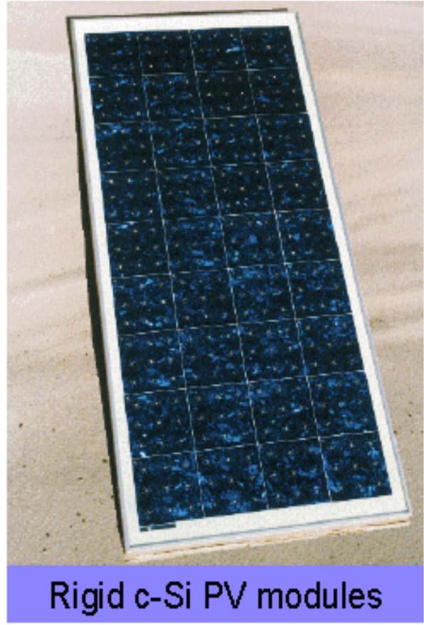
56 Silicon PV s work well and dominate the market

57 Silicon dominates the solar cell market It s relatively expensive and mature 1954


58 What s wrong with the existing technology? It s too expensive Production cost of energy (DOE, 2002)
59 Solar Cell Development Strategies First Generation: A single p n junction diode balance of manufacturing cost, system lifetime, and solar conversion efficiency (i.e., c Si) Second Generation: Thin film deposits reduced cost in manufacturing and substrate materials (i.e., pc Si, a Si, CIS, CISG, CdTe, multi junction, etc.) Third Generation: Non conventional methods (not p n junction) such as photochemical cells, polymer solar cells, dye sensitized solar cells, nano crystal solar cells, and quantum dot solar cells Fourth Generation: Composite photovoltaic technology polymers with nano particles, multi spectrum layers, extremely thin absorber (ETA), low cost, flexible, printable solar cells, and others.

60 Efficiency and Technology
61 Absorber materials less than a few μm thick: Silicon thin films (a-si:h, a-sige:h, μc-si:h,proto c-si, poly c-si:h) II-VI compounds (CdTe) II-IV-VI compounds (CuInSe 2, CuInGaSe 2 )- Copper Indium Gallium Diselenide Cu(In, Ga)Se 2 CIGS Thin film crystalline Si or GaAs (lift-off) Dye-sensitized nano crystalline TiO 2 (nc-tio 2 ) Fully organic solar cells Nanoscienze - M Scarselli 61
62 Thin Film Thin film of semiconductor 1-10 m compared to m Created by depositing a thin expensive semiconductor on a cheaper glass substrate Advantages Requires little semiconductor material Cheaper to produce: glass is cheap semiconductor expensive Disadvantages Difficult to manufacture good films Lower efficiencies Nanoscienze - M Scarselli 62
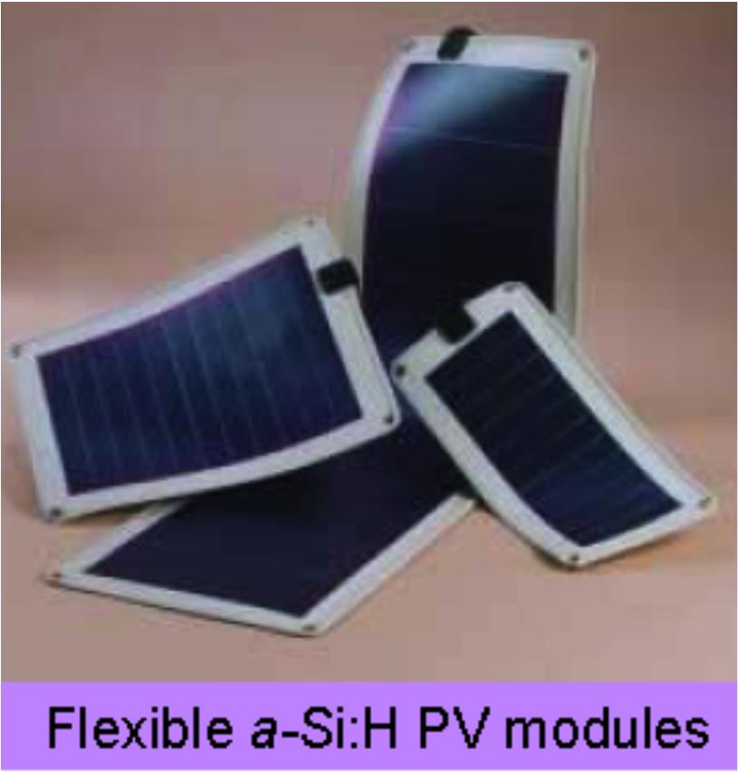
63 Amorphous silicon (a-si) Is obtained by depositing silicon film on tin-doped indium oxide (ITO) covered glass plate. The layer thickness ranges from 1 to 3 µm!! Thin film SC! It can be passivated by hydrogen (a-si:h). Hydrogenated amorphous silicon has a low amount of defects to be used within devices. However, hydrogenation is associated with light-induced degradation of the material. Crystalline Si has indirect band gap whereas a-si has an optical absorption expected for a crystal with direct band gap of 1.6 ev. The efficiency of amorphous cells is much lower than that of the other two cell types. Nanoscienze - M Scarselli 63

64 Nanoscienze - M Scarselli 64

65 FEATURES of THIN film SOLAR CELLS Nanoscienze - M Scarselli 65
 Disadvantages Gallium and Indium are scarce materials Requires expensive vacuum processing Nanoscienze - M")
66 Copper Indium Gallium Diselenide (CIGS) Extremely good light absorption (99% of light absorbed in the first micron) The addition of Ga boosts its light absorption band gap for the solar spectrum No performance degradation over time Much higher efficiencies than other thin films (19%) Disadvantages Gallium and Indium are scarce materials Requires expensive vacuum processing Nanoscienze - M Scarselli 66
67 Multi-Junction III-V Cells Stacked p-n junctions on top of each other Each junction has a different band gap energy so each will respond to a different part of the solar spectrum Very high efficiencies, but more expensive Each junction absorbs what it can and lets the remaining light pass onto the next junction Widely used for space applications because they are very expensive Overall record for electrical efficiency is 35.2% Nanoscienze - M Scarselli 67
68 Terrestrial application Thin FILMS CIGS CdTe Poly c-si TF Si Organic a-si:h 19 % 16 % 16% 9 % 13% 11% 9% Bulk c-si Mono Multi C-Si C-Si Space application GaAs C-Si % % 24 % 12 % 18 % Nanoscienze - M Scarselli 68


69 Solar cells (photovoltaic cells) are the most common continuous electricity source on spacecraft, their first use in space dates back to They convert the radiation energy of the solar light into electricity and may work for a very long time limited only by their aging (that in the space environment goes quicker because the cells are continuously degrade due to bombardment by micrometeorites and cosmic rays). Nanoscienze - M Scarselli 69

70 They also have drawbacks: First, to get high power values large cells surfaces are needed. Second, the angles of incidence can be different from 90 therefore the output is smaller. The output also decreases as square distance from the Sun. That means that on distant space probes (sent to the Mars or to the outer planets and asteroids) solar cells are much less effective than on the Earth s orbit. However, solar cells have been used on Mars orbiters (for example, Viking, Mars Reconnaissance Orbiter etc.) and on Mars landers & rovers (Phoenix, Mars Exploration Rovers). Solar cells are usually made of GaAs instead of Si much more expensive. Nanoscienze - M Scarselli 70

 3.")
71 Dye Sensitive Solar Cell (DSC) Dye Electrolyte M. Grätzel and B. O Regan 1991 TiO 2 1. A wide band gap oxide semiconductor TiO 2 (anatase). 2. Onto the surface of the nano-crystalline film is attached a monolayer of the charge transfer dye. (photoactive element) 3. The electrolyte, usually an organic solvent containing redox system such as the iodide/triiodide helps to restore the dye to its original state. Ref. : M. Grätzel / J. Photochemistry and Photobiology A: Chemistry 164 (2004) 3. Nanoscienze - M Scarselli 71
72 ABOUT TiO2 TiO2 occurs naturally as minerals: rutile, anatase or brookite. The brookite phase is stable only at very low temperatures and hence not so useful practically. The rutile and anatase forms have significant technological usefullness, owing, in large measure, to their optical properties: both are transparent in the visible and absorb in the near ultraviolet. The rutile (110) surface serves as a prototype model for basic studies of oxide surfaces. At room temperature the direct gap Eg is 3.06 ev for rutile and about 3.3 ev for anatase. Nanoscienze - M Scarselli 72
73 Principles of operation In contrast to the conventional silicon systems, where the semiconductor assumes both the task of light absorption and charge carrier transport the two functions are separated here. Light is absorbed by a sensitizer, which is anchored to the surface of a wide band gap oxide semiconductor. Charge separation takes place at the interface via photo-induced electron injection from the dye into the conduction band of the solid. Carriers are transported in the conduction band of the semiconductor to the charge collector. Nanoscienze - M Scarselli 73


74 Photo-excitation of the sensitizer (S) is followed by electron injection into the conduction band of a semiconductor oxide film. The dye The molecule voltage is regenerated under by theillumination redox system, corresponds which itself to the is difference regenerated between at the counter the Fermi electrode level ofby theelectrons passed in the solid through and the redox load. potential of the electrolyte. Overall the device generates electric power from light without suffering any permanent chemical transformation. Nanoscienze - M Scarselli 74
75 Film Morphology The first DSC made in the laboratory used a titanium sheet covered with a high-surface-area "fractal" TiO 2 film. The most widely used nanocrystalline semiconductor oxide electrode in the DSC as an electron collector to support a molecular or QD sensitizer is TiO 2, other wide-band semiconductor oxides such as ZnO, SnO 2,orNb 2 O 5 can be employed. These semiconductor oxides have high surface area which helps in sensitizer binding and efficient solar harvesting. The 50-70% porosity allows facile diffusion of redox mediators within the film to react with surface-bound sensitizers. The density of unfilled acceptor states can be widely and reversibly tuned in energy for increasing light to electrical energy conversion efficiencies. Nanoscienze - M Scarselli 75
 or tin-doped indium oxide (ITO).")
76 10 m Scanning electron micrograph of a sintered mesoscopic TiO 2 film supported on an FTO glass. Nanoparticles of the oxide are deposited onto a glass or flexible plastic support covered with a transparent conducting layer of fluorine-doped tin dioxide (FTO) or tin-doped indium oxide (ITO). Each particle is then coated with a monolayer of sensitizer or a QD formed by self-assembly from a staining solution. Thenanoparticleactsasascaffoldtoholdthedyemoleculesintoits 3-dim array. Nanoscienze - M Scarselli 76

 enhancing dye attachment, porosity, and consequently, photoelectron production.")
77 Small size Becauseofthesmallsizeofthetitaniumdioxidenanoparticles( nanometers), many dye molecules are attached after staining providing many photoelectrons produced. The nanoparticles increase this available surface area times (relative to the area of the glass squares) enhancing dye attachment, porosity, and consequently, photoelectron production. Nanoscienze - M Scarselli 77
78 About TiO2 There is no need to dope the oxide film since the injection of one single electron from the surface adsorbed sensitizer into a TiO 2 nanoparticle is enough to turn the latter from an insulating to a conductive state. In addition, there is no space charge limitation on the photocurrent as the charge of the injected electrons can be effectively screened by the electrolyte surrounding the oxide nanocrystal. A striking and unexpected behavior of the mesoporous TiO 2 films is that the high surface roughness does not promote charge carrier loss by recombination. The reason for this behavior is that the electron and the positive charge find themselves within picoseconds after light excitation of the dye on opposite sides of the liquid solid interface. Nanoscienze - M Scarselli 78
79 The dye The dye must carry attachment groups such as carboxylate or phosphonate to firmly graft it to the semiconductor oxide surface. Depending upon the dye used, different energy levels of photons are absorbed. The goal is to maximize absorption over the visible solar spectrum to produce the maximum energized electrons. Sensitizers having the general structure ML2(X)2 where L stands for 2,2-bipyridyl-4,4-dicarboxylic acid M is Ru or Os and X presents a halide, cyanide, thiocyanate, acetyl acetonate, thiacarbamate or water substituent, are particularly promising. Thus, the Ru complex cis-rul2(ncs)2, known as N3 dye has become the paradigm of heterogeneous charge transfer sensitizer for mesoporous solar cells. Nanoscienze - M Scarselli 79


80 Upon excitation it should inject electrons into the solid with a quantum yield of unity. The energy level of the excited state should be well matched to the lower bound of the conduction band of the oxide to minimize energetic losses during the electron transfer reaction. Its redox potential should be sufficiently positive that it can be regenerated via electron donation from the redox electrolyte or the hole conductor. Itshouldbestableenoughtosustainabout108turnovercycles corresponding to about 20 years of exposure to natural light. Nanoscienze - M Scarselli 80
, the fill factor of the cell (FF) and the intensity of the incident light (I s = 1000 W/m 2 ) η global = i ph V oc FF/Is Nanoscienze - M Scarselli 81")
81 The overall efficiency (η global ) of the photovoltaic cell is calculated from the integral photocurrent density (i ph ), the open circuit photovoltage (V oc ), the fill factor of the cell (FF) and the intensity of the incident light (I s = 1000 W/m 2 ) η global = i ph V oc FF/Is Nanoscienze - M Scarselli 81
82 DSSC compared to traditional silicon-based solar cell Advantages Low cost materials No elaborate apparatus Works in low light conditions High price/performance ratio Disadvantages Slightly lower efficiencies Breakdown of the dye Band gap slightly larger than silicon (fewer solar photons able to produce a current) Liquid electrolyte can leak Nanoscienze - M Scarselli 82
Chapter 7. Solar Cell
 Chapter 7 Solar Cell 7.0 Introduction Solar cells are useful for both space and terrestrial application. Solar cells furnish the long duration power supply for satellites. It converts sunlight directly
Electron Energy, E E = 0. Free electron. 3s Band 2p Band Overlapping energy bands. 3p 3s 2p 2s. 2s Band. Electrons. 1s ATOM SOLID.
 Electron Energy, E Free electron Vacuum level 3p 3s 2p 2s 2s Band 3s Band 2p Band Overlapping energy bands Electrons E = 0 1s ATOM 1s SOLID In a metal the various energy bands overlap to give a single
Mesoporous titanium dioxide electrolyte bulk heterojunction
 Mesoporous titanium dioxide electrolyte bulk heterojunction The term "bulk heterojunction" is used to describe a heterojunction composed of two different materials acting as electron- and a hole- transporters,
3.1 Introduction to Semiconductors. Y. Baghzouz ECE Department UNLV
 3.1 Introduction to Semiconductors Y. Baghzouz ECE Department UNLV Introduction In this lecture, we will cover the basic aspects of semiconductor materials, and the physical mechanisms which are at the
Chapter 1 Overview of Semiconductor Materials and Physics
 Chapter 1 Overview of Semiconductor Materials and Physics Professor Paul K. Chu Conductivity / Resistivity of Insulators, Semiconductors, and Conductors Semiconductor Elements Period II III IV V VI 2 B
Photovoltaic Energy Conversion. Frank Zimmermann
 Photovoltaic Energy Conversion Frank Zimmermann Solar Electricity Generation Consumes no fuel No pollution No greenhouse gases No moving parts, little or no maintenance Sunlight is plentiful & inexhaustible
e - Galvanic Cell 1. Voltage Sources 1.1 Polymer Electrolyte Membrane (PEM) Fuel Cell
 Fuel Cell") Galvanic cells convert different forms of energy (chemical fuel, sunlight, mechanical pressure, etc.) into electrical energy and heat. In this lecture, we are interested in some examples of galvanic cells.
Galvanic cells convert different forms of energy (chemical fuel, sunlight, mechanical pressure, etc.) into electrical energy and heat. In this lecture, we are interested in some examples of galvanic cells.
Electrons are shared in covalent bonds between atoms of Si. A bound electron has the lowest energy state.
 Photovoltaics Basic Steps the generation of light-generated carriers; the collection of the light-generated carriers to generate a current; the generation of a large voltage across the solar cell; and
OPTI510R: Photonics. Khanh Kieu College of Optical Sciences, University of Arizona Meinel building R.626
 OPTI510R: Photonics Khanh Kieu College of Optical Sciences, University of Arizona kkieu@optics.arizona.edu Meinel building R.626 Announcements Homework #6 is assigned, due May 1 st Final exam May 8, 10:30-12:30pm
LEC E T C U T R U E R E 17 -Photodetectors
 LECTURE 17 -Photodetectors Topics to be covered Photodetectors PIN photodiode Avalanche Photodiode Photodetectors Principle of the p-n junction Photodiode A generic photodiode. Photodetectors Principle
ELECTRONIC DEVICES AND CIRCUITS SUMMARY
 ELECTRONIC DEVICES AND CIRCUITS SUMMARY Classification of Materials: Insulator: An insulator is a material that offers a very low level (or negligible) of conductivity when voltage is applied. Eg: Paper,
EE 446/646 Photovoltaic Devices I. Y. Baghzouz
 EE 446/646 Photovoltaic Devices I Y. Baghzouz What is Photovoltaics? First used in about 1890, the word has two parts: photo, derived from the Greek word for light, volt, relating to electricity pioneer
Chemistry Instrumental Analysis Lecture 8. Chem 4631
 Chemistry 4631 Instrumental Analysis Lecture 8 UV to IR Components of Optical Basic components of spectroscopic instruments: stable source of radiant energy transparent container to hold sample device
Photovoltaic cell and module physics and technology
 Photovoltaic cell and module physics and technology Vitezslav Benda, Prof Czech Technical University in Prague benda@fel.cvut.cz www.fel.cvut.cz 6/21/2012 1 Outlines Photovoltaic Effect Photovoltaic cell
February 1, 2011 The University of Toledo, Department of Physics and Astronomy SSARE, PVIC
 FUNDAMENTAL PROPERTIES OF SOLAR CELLS February 1, 2011 The University of Toledo, Department of Physics and Astronomy SSARE, PVIC Principles and Varieties of Solar Energy (PHYS 4400) and Fundamentals of
EE 5344 Introduction to MEMS CHAPTER 5 Radiation Sensors
 EE 5344 Introduction to MEMS CHAPTER 5 Radiation Sensors 5. Radiation Microsensors Radiation µ-sensors convert incident radiant signals into standard electrical out put signals. Radiant Signals Classification
Unit IV Semiconductors Engineering Physics
 Introduction A semiconductor is a material that has a resistivity lies between that of a conductor and an insulator. The conductivity of a semiconductor material can be varied under an external electrical
PN Junctions. Lecture 7
 Lecture 7 PN Junctions Kathy Aidala Applied Physics, G2 Harvard University 10 October, 2002 Wei 1 Active Circuit Elements Why are they desirable? Much greater flexibility in circuit applications. What
Practical 1P4 Energy Levels and Band Gaps
 Practical 1P4 Energy Levels and Band Gaps What you should learn from this practical Science This practical illustrates some of the points from the lecture course on Elementary Quantum Mechanics and Bonding
KATIHAL FİZİĞİ MNT-510
 KATIHAL FİZİĞİ MNT-510 YARIİLETKENLER Kaynaklar: Katıhal Fiziği, Prof. Dr. Mustafa Dikici, Seçkin Yayıncılık Katıhal Fiziği, Şakir Aydoğan, Nobel Yayıncılık, Physics for Computer Science Students: With
Lecture 12. Semiconductor Detectors - Photodetectors
 Lecture 12 Semiconductor Detectors - Photodetectors Principle of the pn junction photodiode Absorption coefficient and photodiode materials Properties of semiconductor detectors The pin photodiodes Avalanche
Designing Information Devices and Systems II A. Sahai, J. Roychowdhury, K. Pister Discussion 1A
 EECS 16B Spring 2019 Designing Information Devices and Systems II A. Sahai, J. Roychowdhury, K. Pister Discussion 1A 1 Semiconductor Physics Generally, semiconductors are crystalline solids bonded into
Practical 1P4 Energy Levels and Band Gaps
 Practical 1P4 Energy Levels and Band Gaps What you should learn from this practical Science This practical illustrates some of the points from the lecture course on Elementary Quantum Mechanics and Bonding
EE495/695 Introduction to Semiconductors I. Y. Baghzouz ECE Department UNLV
 EE495/695 Introduction to Semiconductors I Y. Baghzouz ECE Department UNLV Introduction Solar cells have always been aligned closely with other electronic devices. We will cover the basic aspects of semiconductor
Lecture 15: Optoelectronic devices: Introduction
 Lecture 15: Optoelectronic devices: Introduction Contents 1 Optical absorption 1 1.1 Absorption coefficient....................... 2 2 Optical recombination 5 3 Recombination and carrier lifetime 6 3.1
PHOTOVOLTAICS Fundamentals
 PHOTOVOLTAICS Fundamentals PV FUNDAMENTALS Semiconductor basics pn junction Solar cell operation Design of silicon solar cell SEMICONDUCTOR BASICS Allowed energy bands Valence and conduction band Fermi
Introduction. Katarzyna Skorupska. Silicon will be used as the model material however presented knowledge applies to other semiconducting materials
 Introduction Katarzyna Skorupska Silicon will be used as the model material however presented knowledge applies to other semiconducting materials 2 June 26 Intrinsic and Doped Semiconductors 3 July 3 Optical
Contents CONTENTS. Page 2 of 47
 J. A. Hargreaves Lockerbie Academy June 2015 Contents CONTENTS Contents... 2 CHAPTER 7 CONDUCTORS, SEMICONDUCTORS AND INSULATORS... 4 Summary of Content... 4 Summary of this chapter- notes from column
n N D n p = n i p N A
 Summary of electron and hole concentration in semiconductors Intrinsic semiconductor: E G n kt i = pi = N e 2 0 Donor-doped semiconductor: n N D where N D is the concentration of donor impurity Acceptor-doped
smal band gap Saturday, April 9, 2011
 small band gap upper (conduction) band empty small gap valence band filled 2s 2p 2s 2p hybrid (s+p)band 2p no gap 2s (depend on the crystallographic orientation) extrinsic semiconductor semi-metal electron
Photovoltaic cell and module physics and technology. Vitezslav Benda, Prof Czech Technical University in Prague
 Photovoltaic cell and module physics and technology Vitezslav Benda, Prof Czech Technical University in Prague benda@fel.cvut.cz www.fel.cvut.cz 1 Outlines Photovoltaic Effect Photovoltaic cell structure
1 Name: Student number: DEPARTMENT OF PHYSICS AND PHYSICAL OCEANOGRAPHY MEMORIAL UNIVERSITY OF NEWFOUNDLAND. Fall :00-11:00
 1 Name: DEPARTMENT OF PHYSICS AND PHYSICAL OCEANOGRAPHY MEMORIAL UNIVERSITY OF NEWFOUNDLAND Final Exam Physics 3000 December 11, 2012 Fall 2012 9:00-11:00 INSTRUCTIONS: 1. Answer all seven (7) questions.
Conductivity and Semi-Conductors
 Conductivity and Semi-Conductors J = current density = I/A E = Electric field intensity = V/l where l is the distance between two points Metals: Semiconductors: Many Polymers and Glasses 1 Electrical Conduction
MODELING THE FUNDAMENTAL LIMIT ON CONVERSION EFFICIENCY OF QD SOLAR CELLS
 MODELING THE FUNDAMENTAL LIMIT ON CONVERSION EFFICIENCY OF QD SOLAR CELLS Ա.Մ.Կեչիյանց Ara Kechiantz Institute of Radiophysics and Electronics (IRPhE), National Academy of Sciences (Yerevan, Armenia) Marseille
A semiconductor is an almost insulating material, in which by contamination (doping) positive or negative charge carriers can be introduced.
 positive or negative charge carriers can be introduced.") Semiconductor A semiconductor is an almost insulating material, in which by contamination (doping) positive or negative charge carriers can be introduced. Page 2 Semiconductor materials Page 3 Energy levels
Semiconductor A semiconductor is an almost insulating material, in which by contamination (doping) positive or negative charge carriers can be introduced. Page 2 Semiconductor materials Page 3 Energy levels
Electro - Principles I
 Electro - Principles I Page 10-1 Atomic Theory It is necessary to know what goes on at the atomic level of a semiconductor so the characteristics of the semiconductor can be understood. In many cases a
Chapter 6: Light-Emitting Diodes
 Chapter 6: Light-Emitting Diodes Photoluminescence and electroluminescence Basic transitions Luminescence efficiency Light-emitting diodes Internal quantum efficiency External quantum efficiency Device
Lecture 2. Photon in, Electron out: Basic Principle of PV
 Lecture 2 Photon in, Electron out: Basic Principle of PV References: 1. Physics of Solar Cells. Jenny Nelson. Imperial College Press, 2003. 2. Third Generation Photovoltaics: Advanced Solar Energy Conversion.
The photovoltaic effect occurs in semiconductors where there are distinct valence and
 How a Photovoltaic Cell Works The photovoltaic effect occurs in semiconductors where there are distinct valence and conduction bands. (There are energies at which electrons can not exist within the solid)
CME 300 Properties of Materials. ANSWERS: Homework 9 November 26, As atoms approach each other in the solid state the quantized energy states:
 CME 300 Properties of Materials ANSWERS: Homework 9 November 26, 2011 As atoms approach each other in the solid state the quantized energy states: are split. This splitting is associated with the wave
ET3034TUx Utilization of band gap energy
 ET3034TUx - 3.3.1 - Utilization of band gap energy In the last two weeks we have discussed the working principle of a solar cell and the external parameters that define the performance of a solar cell.
Introduction to Photovoltaics
 INTRODUCTION Objectives Understand the photovoltaic effect. Understand the properties of light. Describe frequency and wavelength. Understand the factors that determine available light energy. Use software
Review of Optical Properties of Materials
 Review of Optical Properties of Materials Review of optics Absorption in semiconductors: qualitative discussion Derivation of Optical Absorption Coefficient in Direct Semiconductors Photons When dealing
Photodiodes and other semiconductor devices
 Photodiodes and other semiconductor devices Chem 243 Winter 2017 What is a semiconductor? no e - Empty e levels Conduction Band a few e - Empty e levels Filled e levels Filled e levels lots of e - Empty
Chapter 4. Photodetectors
 Chapter 4 Photodetectors Types of photodetectors: Photoconductos Photovoltaic Photodiodes Avalanche photodiodes (APDs) Resonant-cavity photodiodes MSM detectors In telecom we mainly use PINs and APDs.
FIBER OPTICS. Prof. R.K. Shevgaonkar. Department of Electrical Engineering. Indian Institute of Technology, Bombay. Lecture: 12.
 FIBER OPTICS Prof. R.K. Shevgaonkar Department of Electrical Engineering Indian Institute of Technology, Bombay Lecture: 12 Optical Sources Fiber Optics, Prof. R.K. Shevgaonkar, Dept. of Electrical Engineering,
FYS3410 Condensed matter physics
 FYS3410 Condensed matter physics Lecture 23 and 24: pn-junctions and electrooptics Randi Haakenaasen UniK/UiO Forsvarets forskningsinstitutt 11.05.2016 and 18.05.2016 Outline Why pn-junctions are important
MTLE-6120: Advanced Electronic Properties of Materials. Semiconductor p-n junction diodes. Reading: Kasap ,
 MTLE-6120: Advanced Electronic Properties of Materials 1 Semiconductor p-n junction diodes Reading: Kasap 6.1-6.5, 6.9-6.12 Metal-semiconductor contact potential 2 p-type n-type p-type n-type Same semiconductor
Photonic Devices. Light absorption and emission. Transitions between discrete states
 Light absorption and emission Photonic Devices Transitions between discrete states Transition rate determined by the two states: Fermi s golden rule Absorption and emission of a semiconductor Vertical
Advantages / Disadvantages of semiconductor detectors
 Advantages / Disadvantages of semiconductor detectors Semiconductor detectors have a high density (compared to gas detector) large energy loss in a short distance diffusion effect is smaller than in gas
3.1 Absorption and Transparency
 3.1 Absorption and Transparency 3.1.1 Optical Devices (definitions) 3.1.2 Photon and Semiconductor Interactions 3.1.3 Photon Intensity 3.1.4 Absorption 3.1 Absorption and Transparency Objective 1: Recall
Engineering 2000 Chapter 8 Semiconductors. ENG2000: R.I. Hornsey Semi: 1
 Engineering 2000 Chapter 8 Semiconductors ENG2000: R.I. Hornsey Semi: 1 Overview We need to know the electrical properties of Si To do this, we must also draw on some of the physical properties and we
Energetic particles and their detection in situ (particle detectors) Part II. George Gloeckler
 Part II. George Gloeckler") Energetic particles and their detection in situ (particle detectors) Part II George Gloeckler University of Michigan, Ann Arbor, MI University of Maryland, College Park, MD Simple particle detectors Gas-filled
Energetic particles and their detection in situ (particle detectors) Part II George Gloeckler University of Michigan, Ann Arbor, MI University of Maryland, College Park, MD Simple particle detectors Gas-filled
Flexible Organic Photovoltaics Employ laser produced metal nanoparticles into the absorption layer 1. An Introduction
 Flexible Organic Photovoltaics Employ laser produced metal nanoparticles into the absorption layer 1. An Introduction Among the renewable energy sources that are called to satisfy the continuously increased
Single Photon detectors
 Single Photon detectors Outline Motivation for single photon detection Semiconductor; general knowledge and important background Photon detectors: internal and external photoeffect Properties of semiconductor
Chapter 3 Modeling and Simulation of Dye-Sensitized Solar Cell
 Chapter 3 Modeling and Simulation of Dye-Sensitized Solar Cell 3.1. Introduction In recent years, dye-sensitized solar cells (DSSCs) based on nanocrystalline mesoporous TiO 2 films have attracted much
EE 5611 Introduction to Microelectronic Technologies Fall Tuesday, September 23, 2014 Lecture 07
 EE 5611 Introduction to Microelectronic Technologies Fall 2014 Tuesday, September 23, 2014 Lecture 07 1 Introduction to Solar Cells Topics to be covered: Solar cells and sun light Review on semiconductor
Solar Cell Materials and Device Characterization
 Solar Cell Materials and Device Characterization April 3, 2012 The University of Toledo, Department of Physics and Astronomy SSARE, PVIC Principles and Varieties of Solar Energy (PHYS 4400) and Fundamentals
Electronics The basics of semiconductor physics
 Electronics The basics of semiconductor physics Prof. Márta Rencz, Gergely Nagy BME DED September 16, 2013 The basic properties of semiconductors Semiconductors conductance is between that of conductors
Basic cell design. Si cell
 Basic cell design Si cell 1 Concepts needed to describe photovoltaic device 1. energy bands in semiconductors: from bonds to bands 2. free carriers: holes and electrons, doping 3. electron and hole current:
Metal Vapour Lasers Use vapoured metal as a gain medium Developed by W. Silfvast (1966) Two types: Ionized Metal vapour (He-Cd) Neutral Metal vapour
 Two types: Ionized Metal vapour (He-Cd) Neutral Metal vapour") Metal Vapour Lasers Use vapoured metal as a gain medium Developed by W. Silfvast (1966) Two types: Ionized Metal vapour (He-Cd) Neutral Metal vapour (Cu) All operate by vaporizing metal in container Helium
Metal Vapour Lasers Use vapoured metal as a gain medium Developed by W. Silfvast (1966) Two types: Ionized Metal vapour (He-Cd) Neutral Metal vapour (Cu) All operate by vaporizing metal in container Helium
5. Semiconductors and P-N junction
 5. Semiconductors and P-N junction Thomas Zimmer, University of Bordeaux, France Summary Learning Outcomes... 2 Physical background of semiconductors... 2 The silicon crystal... 2 The energy bands... 3
Quantum Dot Solar Cells
 Quantum Dot Solar Cells 2 INTRODUCTION: As industrialization speeds up in developing and under-developed countries with an alarming rise in population, global power consumption has become a big question
Goal for next generation solar cells: Efficiencies greater than Si with low cost (low temperature) processing
 processing") Multi-junction cells MBE growth > 40% efficient Expensive Single crystal Si >20% efficient expensive Thin film cells >10% efficient Less expensive Toxic materials Polymers
Multi-junction cells MBE growth > 40% efficient Expensive Single crystal Si >20% efficient expensive Thin film cells >10% efficient Less expensive Toxic materials Polymers
A. OTHER JUNCTIONS B. SEMICONDUCTOR HETEROJUNCTIONS -- MOLECULES AT INTERFACES: ORGANIC PHOTOVOLTAIC BULK HETEROJUNCTION DYE-SENSITIZED SOLAR CELL
 A. OTHER JUNCTIONS B. SEMICONDUCTOR HETEROJUNCTIONS -- MOLECULES AT INTERFACES: ORGANIC PHOTOVOLTAIC BULK HETEROJUNCTION DYE-SENSITIZED SOLAR CELL February 9 and 14, 2012 The University of Toledo, Department
Semiconductor Physics. Lecture 3
 Semiconductor Physics Lecture 3 Intrinsic carrier density Intrinsic carrier density Law of mass action Valid also if we add an impurity which either donates extra electrons or holes the number of carriers
SEMICONDUCTOR PHYSICS
 SEMICONDUCTOR PHYSICS by Dibyendu Chowdhury Semiconductors The materials whose electrical conductivity lies between those of conductors and insulators, are known as semiconductors. Silicon Germanium Cadmium
SEMICONDUCTOR PHYSICS REVIEW BONDS,
 SEMICONDUCTOR PHYSICS REVIEW BONDS, BANDS, EFFECTIVE MASS, DRIFT, DIFFUSION, GENERATION, RECOMBINATION February 3, 2011 The University of Toledo, Department of Physics and Astronomy SSARE, PVIC Principles
3.003 Principles of Engineering Practice
 3.003 Principles of Engineering Practice One Month Review Solar Cells The Sun Semiconductors pn junctions Electricity 1 Engineering Practice 1. Problem Definition 2. Constraints 3. Options 4. Analysis
Two-dimensional lattice
 Two-dimensional lattice a 1 *, k x k x =0,k y =0 X M a 2, y Γ X a 2 *, k y a 1, x Reciprocal lattice Γ k x = 0.5 a 1 *, k y =0 k x = 0, k y = 0.5 a 2 * k x =0.5a 1 *, k y =0.5a 2 * X X M k x = 0.25 a 1
Photonic Communications Engineering Lecture. Dr. Demetris Geddis Department of Engineering Norfolk State University
 Photonic Communications Engineering Lecture Dr. Demetris Geddis Department of Engineering Norfolk State University Light Detectors How does this detector work? Image from visionweb.com Responds to range
Chapter 4 Scintillation Detectors
 Med Phys 4RA3, 4RB3/6R03 Radioisotopes and Radiation Methodology 4-1 4.1. Basic principle of the scintillator Chapter 4 Scintillation Detectors Scintillator Light sensor Ionizing radiation Light (visible,
EE301 Electronics I , Fall
 EE301 Electronics I 2018-2019, Fall 1. Introduction to Microelectronics (1 Week/3 Hrs.) Introduction, Historical Background, Basic Consepts 2. Rewiev of Semiconductors (1 Week/3 Hrs.) Semiconductor materials
Basic Limitations to Third generation PV performance
 Basic Limitations to Third generation PV performance Pabitra K. Nayak Weizmann Institute of Science, Rehovot, Israel THANKS to my COLLEAGUES Lee Barnea and David Cahen. Weizmann Institute of Science Juan
Transparent TiO 2 nanotube/nanowire arrays on TCO coated glass substrates: Synthesis and application to solar energy conversion
 Transparent TiO 2 nanotube/nanowire arrays on TCO coated glass substrates: Synthesis and application to solar energy conversion Craig A. Grimes Department of Electrical Engineering Center for Solar Nanomaterials
Course overview. Me: Dr Luke Wilson. The course: Physics and applications of semiconductors. Office: E17 open door policy
 Course overview Me: Dr Luke Wilson Office: E17 open door policy email: luke.wilson@sheffield.ac.uk The course: Physics and applications of semiconductors 10 lectures aim is to allow time for at least one
Stepwise Solution Important Instructions to examiners:
 (ISO/IEC - 700-005 Certified) SUMMER 05 EXAMINATION Subject Code: 70 Model Answer (Applied Science- Physics) Page No: 0/6 Que. No. Sub. Que. Important Instructions to examiners: ) The answers should be
B12: Semiconductor Devices
 B12: Semiconductor Devices Example Sheet 2: Solutions Question 1 To get from eq. (5.70) of the notes to the expression given in the examples sheet, we simply invoke the relations n 0 p 0, n 0 n 0. In this
Nanotechnology and Solar Energy. Solar Electricity Photovoltaics. Fuel from the Sun Photosynthesis Biofuels Split Water Fuel Cells
 Nanotechnology and Solar Energy Solar Electricity Photovoltaics Fuel from the Sun Photosynthesis Biofuels Split Water Fuel Cells Solar cell A photon from the Sun generates an electron-hole pair in a semiconductor.
Lecture 2. Introduction to semiconductors Structures and characteristics in semiconductors
 Lecture 2 Introduction to semiconductors Structures and characteristics in semiconductors Semiconductor p-n junction Metal Oxide Silicon structure Semiconductor contact Literature Glen F. Knoll, Radiation
Introduction to Semiconductor Physics. Prof.P. Ravindran, Department of Physics, Central University of Tamil Nadu, India
 Introduction to Semiconductor Physics 1 Prof.P. Ravindran, Department of Physics, Central University of Tamil Nadu, India http://folk.uio.no/ravi/cmp2013 Review of Semiconductor Physics Semiconductor fundamentals
Semiconductor Detectors
 Semiconductor Detectors Summary of Last Lecture Band structure in Solids: Conduction band Conduction band thermal conductivity: E g > 5 ev Valence band Insulator Charge carrier in conductor: e - Charge
Electronic Circuits for Mechatronics ELCT 609 Lecture 2: PN Junctions (1)
") Electronic Circuits for Mechatronics ELCT 609 Lecture 2: PN Junctions (1) Assistant Professor Office: C3.315 E-mail: eman.azab@guc.edu.eg 1 Electronic (Semiconductor) Devices P-N Junctions (Diodes): Physical
Electronic Circuits for Mechatronics ELCT 609 Lecture 2: PN Junctions (1) Assistant Professor Office: C3.315 E-mail: eman.azab@guc.edu.eg 1 Electronic (Semiconductor) Devices P-N Junctions (Diodes): Physical
The Electromagnetic Properties of Materials
 The Electromagnetic Properties of Materials Electrical conduction Metals Semiconductors Insulators (dielectrics) Superconductors Magnetic materials Ferromagnetic materials Others Photonic Materials (optical)
FYS 3028/8028 Solar Energy and Energy Storage. Calculator with empty memory Language dictionaries
 Faculty of Science and Technology Exam in: FYS 3028/8028 Solar Energy and Energy Storage Date: 11.05.2016 Time: 9-13 Place: Åsgårdvegen 9 Approved aids: Type of sheets (sqares/lines): Number of pages incl.
Classification of Solids
 Classification of Solids Classification by conductivity, which is related to the band structure: (Filled bands are shown dark; D(E) = Density of states) Class Electron Density Density of States D(E) Examples
Lecture 9: Metal-semiconductor junctions
 Lecture 9: Metal-semiconductor junctions Contents 1 Introduction 1 2 Metal-metal junction 1 2.1 Thermocouples.......................... 2 3 Schottky junctions 4 3.1 Forward bias............................
Chapter 1. Solar energy conversion: from amorphous silicon to Dye-Sensitized Solar Cells. 1.1 Photovoltaic history.
 Chapter 1 Solar energy conversion: from amorphous silicon to Dye-Sensitized Solar Cells 1.1 Photovoltaic history. 1.2 Operation of traditional photovoltaic devices. 1.3 Thin film solar cells. 1.4 Multijunction
ELEMENTARY BAND THEORY
 ELEMENTARY BAND THEORY PHYSICIST Solid state band Valence band, VB Conduction band, CB Fermi energy, E F Bloch orbital, delocalized n-doping p-doping Band gap, E g Direct band gap Indirect band gap Phonon
Two-dimensional lattice
 1 Two-dimensional lattice a 1 *, k x k x = 0, k y = 0 X M a 2, y a 1, x Γ X a 2 *, k y k x = 0.5 a 1 *, k y = 0 k x = 0, k y = 0.5 a 2 * Γ k x = 0.5 a 1 *, k y = 0.5 a 2 * X X M k x = 0.25 a 1 *, k y =
Solar cells operation
 Solar cells operation photovoltaic effect light and dark V characteristics effect of intensity effect of temperature efficiency efficency losses reflection recombination carrier collection and quantum
Photonics and Optical Communication
 Photonics and Optical Communication (Course Number 300352) Spring 2007 Optical Source Dr. Dietmar Knipp Assistant Professor of Electrical Engineering http://www.faculty.iu-bremen.de/dknipp/ 1 Photonics
Semiconductor-Detectors
 Semiconductor-Detectors 1 Motivation ~ 195: Discovery that pn-- junctions can be used to detect particles. Semiconductor detectors used for energy measurements ( Germanium) Since ~ 3 years: Semiconductor
Photonic Devices Human eye: about 400 nm to 700 nm
 Photonic Devices Human eye: about 400 nm to 700 nm λ [ nm] = 1240 E[ ev ] S. M. Sze, Physics of Semiconductor Devices Sensitivity of the human eye Two LEDs: red (λ = 660 nm) green (λ = 560 nm) emitting
* motif: a single or repeated design or color
 Chapter 2. Structure A. Electronic structure vs. Geometric structure B. Clean surface vs. Adsorbate covered surface (substrate + overlayer) C. Adsorbate structure - how are the adsorbed molecules bound
This is the 15th lecture of this course in which we begin a new topic, Excess Carriers. This topic will be covered in two lectures.
 Solid State Devices Dr. S. Karmalkar Department of Electronics and Communication Engineering Indian Institute of Technology, Madras Lecture - 15 Excess Carriers This is the 15th lecture of this course
Current mechanisms Exam January 27, 2012
 Current mechanisms Exam January 27, 2012 There are four mechanisms that typically cause currents to flow: thermionic emission, diffusion, drift, and tunneling. Explain briefly which kind of current mechanisms
Photocatalysis: semiconductor physics
 Photocatalysis: semiconductor physics Carlos J. Tavares Center of Physics, University of Minho, Portugal ctavares@fisica.uminho.pt www.fisica.uminho.pt 1 Guimarães Where do I come from? 3 Guimarães 4 Introduction>>
Semiconductors and Optoelectronics. Today Semiconductors Acoustics. Tomorrow Come to CH325 Exercises Tours
 Semiconductors and Optoelectronics Advanced Physics Lab, PHYS 3600 Don Heiman, Northeastern University, 2017 Today Semiconductors Acoustics Tomorrow Come to CH325 Exercises Tours Semiconductors and Optoelectronics
Physics Department. CfE Higher Unit 3: Electricity. Problem Booklet
 Physics Department CfE Higher Unit 3: Electricity Problem Booklet Name Class 1 Contents Exercise 1: Monitoring and measuring a.c. Exercise 2: Current, voltage, power and resistance Exercise 3: Electrical