Chapter 7. Introduction to Fluid Machinery
|
|
|
- Cecily Baldwin
- 6 years ago
- Views:
Transcription
1 Chapter 7 Introduction to Fluid Machinery 1
2 Classification of Fluid Machines Positive diplacement machines (static type) Turbomachines (dynamic type) Turbines: extract energy to the flow :the fluid does work on them Pumps: add energy to the flow = do work to the fluid Pumps Fans Blowers Compressor
3 Positive diplacement machines force a fluid into or out of a chamber by changing the volume of the chamber. Typical positive displacement pumps: (a) tire pump, (b) human heart, (c) gear pump, (d) Peristaltic pump. (d) From fundamentals of fluid mechanichs Monson (5th edition) Young Okiishi Wiley 3
4 Turbomachines Machines for Doing Work on a Fluid Pumps Fans Blowers Compressors Machines for Extracting Work (Power) from a Fluid Hydraulic Turbines Gas Turbines Wind-Power Machines 4


5 Machines for Doing Work on a Fluid Centrifugal Blower Centrifugal Pump left ventricular assist devices Fan 5
 (a) Open impeller, (b)")


6 Figure 1.7 (p. 694) (a) Open impeller, (b) enclosed or shrouded impeller. (Courtesy of Ingersoll- Dresser Pump Company). From fundamentals of fluid mechanichs Monson (5th edition) Young Okiishi Wiley 6


7 Machines for Extracting Work Very simple impulse turbine Impulse turbine Propeller turbine: Kaplan type Windmill 7
 Absolute fluid velocity V = W + U (that seen by a person sitting")
8 Turbomachinery Analysis Blade speed U = ω r r : radial distance from the axis of the fan. ω:angular velocity Relative velocity W (that seen by a person riding on the fan blade) Absolute fluid velocity V = W + U (that seen by a person sitting stationary at the table on which the fan rests) Fan = pump = do work 8

9 Turbomachinery Analysis Blade speed U = ω r r : radial distance from the axis of the fan. ω:angular velocity Relative velocity W Absolute fluid velocity V = W + U Home work: coloring Windmill = turbine = extracting work Here we are looking for U 9
10 Pump or Turbine? the tangential component of the force of the blade on the fluid is in the direction of the blade motion : PUMPS in the opposite direction of the blade motion : TURBINE W W V=U+W PUMP U V=U+W U TURBINE 10
11 Angular momentum principle Sum of external torques Time rate of change of the moment-ofmomentum in the volume Net rate of flow of moment-ofmomentum Through the surfae control Torque of surface forces Torque of the gravity force Shaft torque : Torque that the shaft applies to the rotor 11
12 Euler turbomachine equation Volume controle enclosing the rotor Steady flow Force due to the surface force may be ignored Gravity may be ignored T shaft CV r VV da Notes: m : flow rate m = ρq = ρvs Vt > 0 if Vt and U are in the same dircetion 1
13 Pump or Turbine? if the shaft torque and the rotation of the rotor are in the same direction: the energy is transferred from the shaft to the rotor and from the rotor to the fluid the machine is a pump if the torque exerted by the shaft on the rotor is opposite to the direction of rotation: the energy transfer is from the fluid to the rotor the machine is a turbine. So if we choose Vt > 0 if Vt and U are in the same direction Tshaft > 0 for PUMPS Tshaft < 0 for TURBINE 13
14 Pump or Turbine? V V Vn V Vt V Vn r Vt r ω r V ω PUMP TURBINE 14
15 Mechanical Power or Shaft Power W m T shaft Using U = r ω and W m 0 PUMP W m 0 TURBINE 15

16 Theoretical Head: Hydraulic head is a specific measurement of total energy per unit weight H It is usually measured as a water surface elevation : 1 m s m m m s s Note: Mechanical Power and Theoretical Head come from angular-moment equation for a control volume then it if for: -Steady flow -Uniform flow at each section 16
17 Example: Idealized Centrifugal Pump Negligible torque due to surface forces (viscous and pressure). Steady flow Inlet and exit flow tangent to blades. Uniform flow at inlet and exit. Zero inlet tangential velocity = purely radial Incompressible flow 17
18 Idealized Centrifugal Pump W V R R 1 U = R ω ω Given: Q, W Find: b, T shaft, Wm Governing equation: Euler turbomachine equation : from momentum Continuity Steady T t shaft CV dv r V CV CS b Vd A 0 V da 18
19 Idealized Centrifugal Pump W r r 1 U = r ω ω Given: Q, W Find: b, T shaft, Wm Then from continuity: V r W r b 0 b 1 1 or the mass flow rate: then m Q W b Q W r r b 19
20 Idealized Centrifugal Pump W r r 1 U = r ω ω Given: Q, W Find: b, T shaft, Wm b V=U+W T shaft r m W = V n U = r ω = V t 0
21 r Idealized Centrifugal Pump r 1 W (case: W normal) U = r ω ω Given: Q, W Find: b, T shaft, W m b W m W m T shaft R m W = V t V=U+W U = r ω = V t 1


22 case: W with a angle β V n V V t Vt Vt n Vt1 0 b V V U W cos U cos U V cot n t n sin
23 H W shaft mg UV g t V n V V t Q rb Vn so, V n Q r b H H become : Q U UV g g g cot U UU V ncot t rb H U Q cot g g r b b Ideal head developed by a pump with Q flow rate 3
24 SUMMARY Torque: Power: t t t t t t t t Theoretical head : W shaft 1 H ( UVt UV 1 t1 ) mg g b 4
25 Performance characteristics For design a pump or a turbine we must know: -Head -Torque -Power requirement -Efficiency Note: The idealized analyses presented previously is useful to predict approximate the performances : It is a stat point for design. But to determined the real performance we must perform measurement of -Head or pressures -Speed -Input torque -Power For different flow rate 5
26 PUMP Head as function of flow rate Effect of losses on the pump head-flowrate curve. 1. Recirculation in the impeler (At low flow rate). Fiction loss (increase with the flow rate) 3. Leakage (increase with the flow rate) From fundamentals of fluid mechanichs Monson (5th edition) Young Okiishi Wiley 4. «shock loss» mismatch between relative velocity direction and the tangent to impeller blade at the inlet (largest at low and hight flow rate, decrease around the optimum operating condition ) 6
27 Performance characteristics For machine doing work on a fluid Pump head: For machine doing work on a fluid: Hp is rate of the mechanical energy input to the fluid Hydraulic Power: Pump Efficiency: Note: in term of horse power WatterHorsePower W h 550 7
28 PUMP Typical performance characteristics for a centrifugal pump of a given size operating at a constant impeller speed. From fundamentals of fluid mechanichs Monson (5th edition) Young Okiishi Wiley 8

29 PUMP To vary pump capacity, we could change the impeller size: Best efficiency point Bhp: brake horse power NPSH: Net positive suction head Performance curves for a two-stage centrifugal pump operating at 3500 rpm. Data given for three different impeller diameters. From fundamentals of fluid mechanichs Monson (5th edition) Young Okiishi Wiley 9
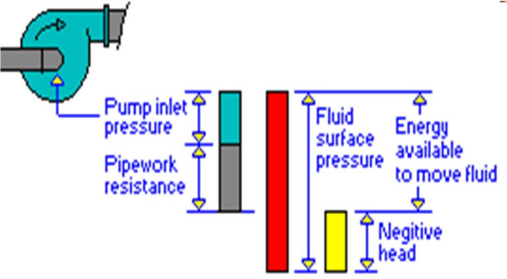
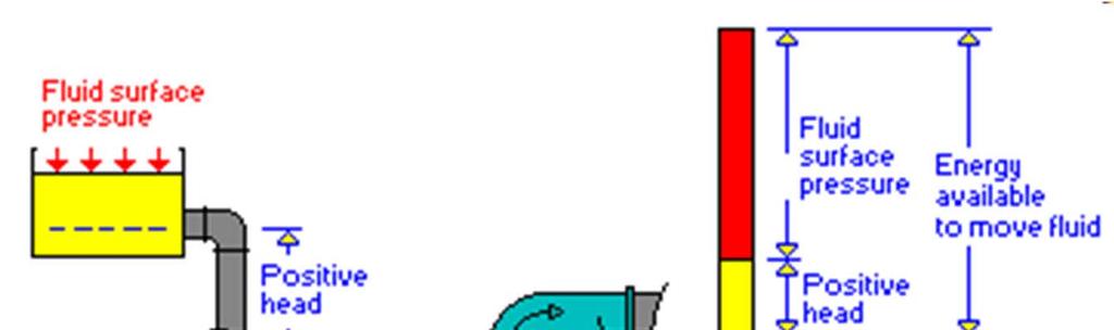
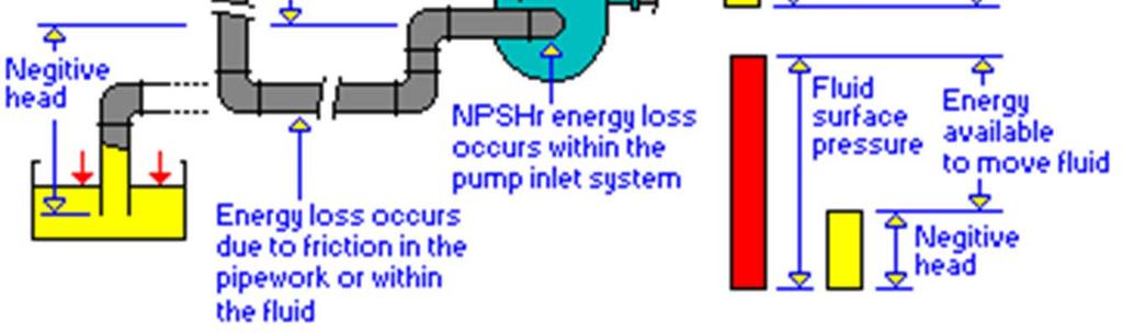
30 PUMP NPSH: Net positive suction head On the suction side of a pump: low pressures possibility of cavitations ( liquid pressure to small bubbles ; liquid boil) loss in efficiency or pump damage NPSH = total Head on the suction side (inlet) liquid vapor pressure NPSH Ps g Vs g Pv g To avoid cavitations NPSH have to be maintained or exceeded. 30

31 PUMP NPSH: Net positive suction head NPSH could be determined experimentally Calculate with known parameters: hl Energy equation: P1 V1 g g z 1 Ps Vs g g z s Head loss between free surface and pump intlet h L V 1 z 0 P1 0 ; s P atm P g atm z 1 Ps g Vs g h L So, Ps g Vs P g g atm z 1 h L Then : NPSH def Ps g Vs g Pv g P g atm z 1 h L Pv g 31
32 Dimensional Analysis Performance may be defined by curves head/flow rate for different values of speed, different flow properties etc But, This would be difficult to represent all the data on a single chart! Flow Coefficient: Head Coefficient: Power Coefficient: Torque Coefficient: DEMO 3
 dimensionless characteristic curves. (Data from Ref. 8, used by permission.")
33 Head Coefficient Power Coefficient Flow Coefficient Typical performance data for a centrifugal pump: (a) characteristic curves for a 1-in. centrifugal pump operating at 1000 rpm, (b) dimensionless characteristic curves. (Data from Ref. 8, used by permission.) From fundamentals of fluid mechanichs Monson (5th edition) Young Okiishi Wiley 33
34 Similarity Rules To achieve dynamic similarity requires geometric and kinetic similarity: Flow Head Power 34
35 Similarity Rules For the same pump (same dimension) working a different speed: Flow Q Q 1 1 Head h h 1 1 Power
 Specific Speed (Customary Units US): N 43. 46N S cu S 36")
36 Specific Speed By combining of Flow and Head coefficient, and eliminating the machine size : N S 1/ 3/ 4 Specific Speed: (dimensionless) Specific Speed (Customary Units US): N N S cu S 36


 From fundamentals of fluid mechanichs")
37 Specific Speed Holding specific speed constant describes all operating conditions of geometrically similar machines with similar condition: Variation in specific speed with type of pump. (adapted from Ref. 10, used with permission.) From fundamentals of fluid mechanichs Monson (5th edition) Young Okiishi Wiley 37
38 Applications to Fluid Systems System equation Application of equation enegy to a control volume consisting af a pump-pipe system: p g V p V z z g g g H p H fl At the outlet of the system At the inlet of the system Head due to the pump only Due to the friction α : Correction factor = for laminar flow close to 1 for hight reynolds number. Cf chap 8 of the text book 38

39 39 p H fl z z H 1 For pipes flows the losses H fl KQ 1 KQ z z H p H p H fl z g V g p z g V g p Applications to Fluid Systems System equation : typical fluid system Flow loss
40 40
41 Applications to Fluid Systems System curve : typical fluid system System curve : system equation & pump performance Intersection represent the operating point If you change the system equation -Change pipe friction (fouling) -Change the watter elevation You will change the operating point Idealy: opreating point close the best efficiency Utilization of the system curve and the pump performance curve to obtain the operating point for the system. 0&feature=iv&src_vid=IiE8skW8btE&v=pWSyrxFJmt4 41

42 Applications to Fluid Systems Pump Wear 4
43 Applications to Fluid Systems -Pumps in Series 43
44 Applications to Fluid Systems Pumps in Parallel 44


45 Centrifugal blood pump Extracorporeal blood pump for cardiac surgery Specific requierements: Avoid hemolysis 45
 tire pump, (b) human heart, (c) gear pump, (d) Peristaltic pump.")
46 Positive diplacement pumps force a fluid into or out of a chamber by changing the volume of the chamber. Typical positive displacement pumps: (a) tire pump, (b) human heart, (c) gear pump, (d) Peristaltic pump. (d) From fundamentals of fluid mechanichs Monson (5th edition) Young Okiishi Wiley 46
47 Positive-Displacement Pumps Fluid with higth viscosity can not be moved with standard centrifugal pump : viscosity above 850 cp (loss efficiency) PD is better! it can work with viscosity changing in a same batch from 1 over 100,000 cp! The majority of problems, both centrifugal and PD start at the suction, There must be a minimum amount of absolute pressure avaible to suplly fluid pum suction. PD pumps generally requiere less absolute pressure than centrifugal pumps. 47
48 PD : Efficency Volumetric efficency = actual volumetric delivery / pump displacement As pressure is raised or pumps speed reduced Overall efficency = power delivred to the fluid / power input to the pump Tends to rise as pump speed increase 48
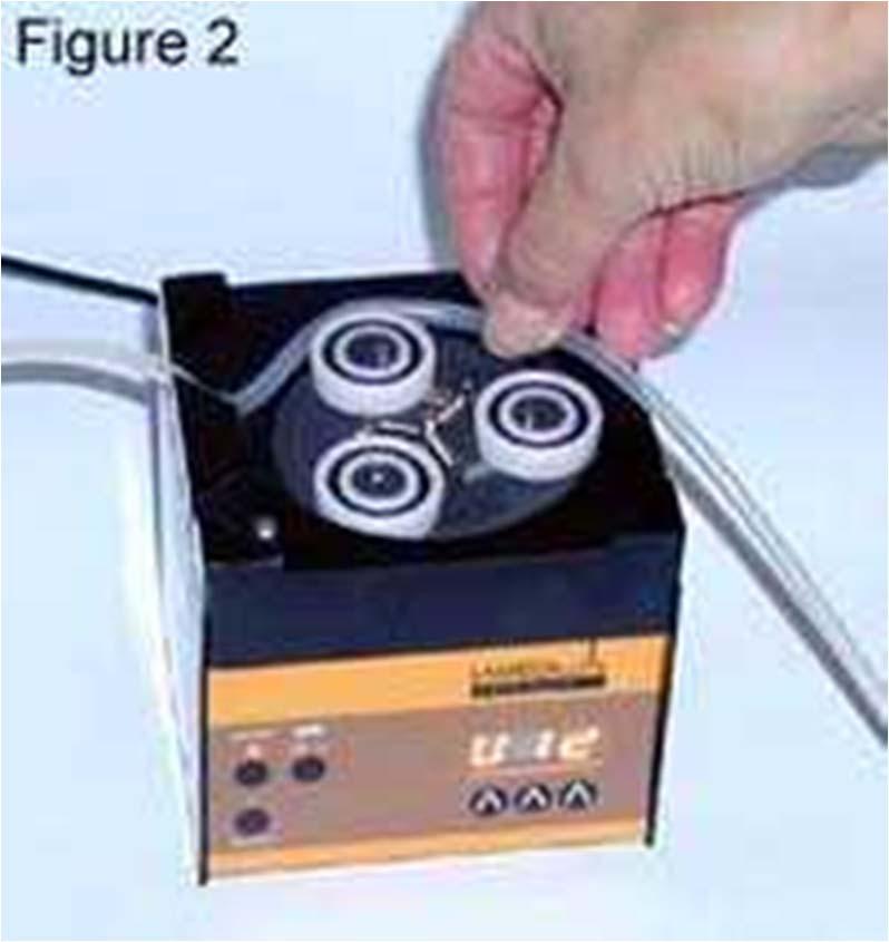
49 Peristaltic pump 49

50 Syringe-pump Modern medical infusion pump 50
51 CHAP. 7- Fluid Machinery Blood pumps Exemples
 As air is evacuated from the device, the diaphragm deforms into the air")
52 Jarvik 7 CardioWest TAH The CardioWest TAH replaces each ventricle with a separate diaphragm-type pump Each pump is divided into two chambers by a flexible diaphragm with blood on one side and air on the other As air is forced into the device, the diaphragm deforms into the blood chamber causing blood ejection (systole) As air is evacuated from the device, the diaphragm deforms into the air chamber causing blood the enter the device (diastole) This device is driven pneumatically by an external console attached to the device by two drivelines that go through the skin The maximum stroke volume in this device is 70 ml with a flow rate of 6 to 8 L/min under normal conditions This device is currently being used in patients under 67 years old who suffer from biventricular failure and are candidates for transplantation
53 Nikkiso The Nikkiso HPM-15 (Nikkiso Co., Ltd., Tokyo, Japan) is an extracorporeal centrifugal blood pump currently in use in Japan for CPB This pump has an impeller with 6 blades Extensive simulations of flow and hemolysis have been performed on this device According to their website, Nikkiso is presently developing an implantable centrifugal pump Nikkiso HPM-15 (from Takiura et al., 1998).

54 HeartQuest VAD Outflow cannula This device makes use of MagLev technology to magnetically suspend the pump impeller Upper housing Currently, this device has a wearable external battery and controller Future versions will make use of TET technology Lower housing Impeller Figure HeartQuest VAD (from Song et al., 004).

55 Impella Recover The Impella Recover (Impella CardioSystems GmbH, Aachen, Germany) is a catheter-based pump offering short term uni- or biventricular support This device is the smallest mechanical circulatory support device in the world The Impella Recover can be inserted via the femoral artery or directly into the left ventricle and provides circulatory support for up to 7 days A portable console is use to drive and control the pump, thus allowing for easy patient transport This device is in use in Europe Impella Recover Pump (from
Chapter Four Hydraulic Machines
 Contents 1- Introduction. - Pumps. Chapter Four Hydraulic Machines (لفرع الميكانيك العام فقط ( Turbines. -3 4- Cavitation in hydraulic machines. 5- Examples. 6- Problems; sheet No. 4 (Pumps) 7- Problems;
Chapter Four Hydraulic Machines
 Contents 1- Introduction. 2- Pumps. Chapter Four Hydraulic Machines (لفرع الميكانيك العام فقط ( Turbines. -3 4- Cavitation in hydraulic machines. 5- Examples. 6- Problems; sheet No. 4 (Pumps) 7- Problems;
ENERGY TRANSFER BETWEEN FLUID AND ROTOR. Dr. Ir. Harinaldi, M.Eng Mechanical Engineering Department Faculty of Engineering University of Indonesia
 ENERGY TRANSFER BETWEEN FLUID AND ROTOR Dr. Ir. Harinaldi, M.Eng Mechanical Engineering Department Faculty of Engineering University of Indonesia Basic Laws and Equations Continuity Equation m m ρ mass
Department of Civil and Environmental Engineering CVNG 1001: Mechanics of Fluids
 INTRODUCTION Hydrodynamic Machines A hydromachine is a device used either for extracting energy from a fluid or to add energy to a fluid. There are many types of hydromachines and Figure 1 below illustrates
CHAPTER EIGHT P U M P I N G O F L I Q U I D S
 CHAPTER EIGHT P U M P I N G O F L I Q U I D S Pupmps are devices for supplying energy or head to a flowing liquid in order to overcome head losses due to friction and also if necessary, to raise liquid
Introduction to Turbomachinery
 1. Coordinate System Introduction to Turbomachinery Since there are stationary and rotating blades in turbomachines, they tend to form a cylindrical form, represented in three directions; 1. Axial 2. Radial
M E 320 Professor John M. Cimbala Lecture 23
 M E 320 Professor John M. Cimbala Lecture 23 Today, we will: Discuss diffusers and do an example problem Begin discussing pumps, and how they are analyzed in pipe flow systems D. Diffusers 1. Introduction.
Turbomachinery. Hasan Ozcan Assistant Professor. Mechanical Engineering Department Faculty of Engineering Karabuk University
 Turbomachinery Hasan Ozcan Assistant Professor Mechanical Engineering Department Faculty of Engineering Karabuk University Introduction Hasan Ozcan, Ph.D, (Assistant Professor) B.Sc :Erciyes University,
CALIFORNIA POLYTECHNIC STATE UNIVERSITY Mechanical Engineering Department ME 347, Fluid Mechanics II, Winter 2018
 CALIFORNIA POLYTECHNIC STATE UNIVERSITY Mechanical Engineering Department ME 347, Fluid Mechanics II, Winter 2018 Date Day Subject Read HW Sept. 21 F Introduction 1, 2 24 M Finite control volume analysis
Objectives. Conservation of mass principle: Mass Equation The Bernoulli equation Conservation of energy principle: Energy equation
 Objectives Conservation of mass principle: Mass Equation The Bernoulli equation Conservation of energy principle: Energy equation Conservation of Mass Conservation of Mass Mass, like energy, is a conserved
SOE2156: Fluids Lecture 4
 Turbo SOE2156: s Lecture 4 machine { a device exchanging energy (work) between a uid and a mechanical system. In particular : a turbomachine is a device using a rotating mechanical system. The ow of energy
vector H. If O is the point about which moments are desired, the angular moment about O is given:
 The angular momentum A control volume analysis can be applied to the angular momentum, by letting B equal to angularmomentum vector H. If O is the point about which moments are desired, the angular moment
CHAPTER TWO CENTRIFUGAL PUMPS 2.1 Energy Transfer In Turbo Machines
 7 CHAPTER TWO CENTRIFUGAL PUMPS 21 Energy Transfer In Turbo Machines Fig21 Now consider a turbomachine (pump or turbine) the total head (H) supplied by it is The power delivered to/by the fluid simply
Application of CFX to Implantable Rotary Blood Pumps Suspended by Magnetic Bearings
 Application of CFX to Implantable Rotary Blood Pumps Suspended by Magnetic Bearings Xinwei Song University of Virginia Houston G. Wood University of Virginia Abstract The University of Virginia has been
Conservation of Angular Momentum
 10 March 2017 Conservation of ngular Momentum Lecture 23 In the last class, we discussed about the conservation of angular momentum principle. Using RTT, the angular momentum principle was given as DHo
Contents. 2 Basic Components Aerofoils Force Generation Performance Parameters xvii
 Contents 1 Working Principles... 1 1.1 Definition of a Turbomachine... 1 1.2 Examples of Axial Turbomachines... 2 1.2.1 Axial Hydraulic Turbine... 2 1.2.2 Axial Pump... 4 1.3 Mean Line Analysis... 5 1.4
Applied Fluid Mechanics
 Applied Fluid Mechanics 1. The Nature of Fluid and the Study of Fluid Mechanics 2. Viscosity of Fluid 3. Pressure Measurement 4. Forces Due to Static Fluid 5. Buoyancy and Stability 6. Flow of Fluid and
CLASS Fourth Units (Second part)
") CLASS Fourth Units (Second part) Energy analysis of closed systems Copyright The McGraw-Hill Companies, Inc. Permission required for reproduction or display. MOVING BOUNDARY WORK Moving boundary work (P
CLASS Fourth Units (Second part) Energy analysis of closed systems Copyright The McGraw-Hill Companies, Inc. Permission required for reproduction or display. MOVING BOUNDARY WORK Moving boundary work (P
9. Pumps (compressors & turbines) Partly based on Chapter 10 of the De Nevers textbook.
 Partly based on Chapter 10 of the De Nevers textbook.") Lecture Notes CHE 31 Fluid Mechanics (Fall 010) 9. Pumps (compressors & turbines) Partly based on Chapter 10 of the De Nevers textbook. Basics (pressure head, efficiency, working point, stability) Pumps
Lecture Notes CHE 31 Fluid Mechanics (Fall 010) 9. Pumps (compressors & turbines) Partly based on Chapter 10 of the De Nevers textbook. Basics (pressure head, efficiency, working point, stability) Pumps
where = rate of change of total energy of the system, = rate of heat added to the system, = rate of work done by the system
 The Energy Equation for Control Volumes Recall, the First Law of Thermodynamics: where = rate of change of total energy of the system, = rate of heat added to the system, = rate of work done by the system
Introduction to Fluid Machines and Compressible Flow Prof. S. K. Som Department of Mechanical Engineering Indian Institute of Technology, Kharagpur
 Introduction to Fluid Machines and Compressible Flow Prof. S. K. Som Department of Mechanical Engineering Indian Institute of Technology, Kharagpur Lecture - 1 Introduction to Fluid Machines Well, good
BASIC EQUATION. Rotational speed. u = linear velocity in m/s r = radius in m ω = angular velocity in rad/s D = diameter in m N = rotation per minute
 CENTRIFUGAL PUMP BASIC EQUATION Rotational speed u = rω = πdn 60 u = linear velocity in m/s r = radius in m ω = angular velocity in rad/s D = diameter in m N = rotation per minute Power Power = F V = P
Angular momentum equation
 Angular momentum equation For angular momentum equation, B =H O the angular momentum vector about point O which moments are desired. Where β is The Reynolds transport equation can be written as follows:
Chapter 6: Momentum Analysis
 6-1 Introduction 6-2Newton s Law and Conservation of Momentum 6-3 Choosing a Control Volume 6-4 Forces Acting on a Control Volume 6-5Linear Momentum Equation 6-6 Angular Momentum 6-7 The Second Law of
COMPUTER AIDED DESIGN OF RADIAL TIPPED CENTRIFUGAL BLOWERS AND FANS
 4 th International Conference on Mechanical Engineering, December 26-28, 21, Dhaka, Bangladesh/pp. IV 55-6 COMPUTER AIDED DESIGN OF RADIAL TIPPED CENTRIFUGAL BLOWERS AND FANS Nitin N. Vibhakar* and S.
Bernoulli s equation may be developed as a special form of the momentum or energy equation.
 BERNOULLI S EQUATION Bernoulli equation may be developed a a pecial form of the momentum or energy equation. Here, we will develop it a pecial cae of momentum equation. Conider a teady incompreible flow
Chapter 4. Turbomachinery. 4.1 Introduction. 4.2 Pumps
 Chapter 4 Turbomachinery 4.1 Introduction In this chapter we will examine the performance characteristics of turbomachinery. The word turbo implies a spinning action is involved. In turbomachinery, a blade
CENTRIFUGAL PUMP SELECTION, SIZING, AND INTERPRETATION OF PERFORMANCE CURVES
 CENTRIFUGAL PUMP SELECTION, SIZING, AND INTERPRETATION OF PERFORMANCE CURVES 4.0 PUMP CLASSES Pumps may be classified in two general types, dynamic and positive displacement. Positive displacement pumps
Chapter Four fluid flow mass, energy, Bernoulli and momentum
 4-1Conservation of Mass Principle Consider a control volume of arbitrary shape, as shown in Fig (4-1). Figure (4-1): the differential control volume and differential control volume (Total mass entering
BASIC EQUATION. Rotational speed = = ABC 60
 CENTRIFUGAL PUMP BASIC EQUATION Rotational speed = =?@ = ABC 60 = = linear velocity in m/s? = radius in m @ = angular velocity in rad/s B = diameter in m C = rotation per minute Power OPQR? = S U = O V
Theory of turbo machine Effect of Blade Configuration on Characteristics of Centrifugal machines. Unit 2 (Potters & Wiggert Sec
 Theory of turbo machine Effect of Blade Configuration on Characteristics of Centrifugal machines Unit (Potters & Wiggert Sec. 1..1, &-607) Expression relating Q, H, P developed by Rotary machines Rotary
COURSE CODE : 3072 COURSE CATEGORY : B PERIODS/ WEEK : 5 PERIODS/ SEMESTER : 75 CREDIT : 5 TIME SCHEDULE
 COURSE TITLE : FLUID MECHANICS COURSE CODE : 307 COURSE CATEGORY : B PERIODS/ WEEK : 5 PERIODS/ SEMESTER : 75 CREDIT : 5 TIME SCHEDULE MODULE TOPIC PERIOD 1 Properties of Fluids 0 Fluid Friction and Flow
Department of Energy Fundamentals Handbook. THERMODYNAMICS, HEAT TRANSFER, AND FLUID FLOW, Module 3 Fluid Flow
 Department of Energy Fundamentals Handbook THERMODYNAMICS, HEAT TRANSFER, AND FLUID FLOW, Module 3 REFERENCES REFERENCES Streeter, Victor L., Fluid Mechanics, 5th Edition, McGraw-Hill, New York, ISBN 07-062191-9.
Engineering Fluid Mechanics
 Engineering Fluid Mechanics Eighth Edition Clayton T. Crowe WASHINGTON STATE UNIVERSITY, PULLMAN Donald F. Elger UNIVERSITY OF IDAHO, MOSCOW John A. Roberson WASHINGTON STATE UNIVERSITY, PULLMAN WILEY
Dr. S. Ramachandran Prof. R. Devaraj. Mr. YVS. Karthick AIR WALK PUBLICATIONS
 Fluid Machinery As per Revised Syllabus of Leading Universities including APJ ABDUL KALAM TECHNOLOGICAL UNIVERSITY Dr. S. Ramachandran Prof. R. Devaraj Professors School of Mechanical Engineering Sathyabama
Centrifugal Machines Table of Contents
 NLNG Course 017 Table of Contents 1 Introduction and Basic Principles... 1.1 Hydraulic Machines... 1.... 1.3 Pump Geometry... 1.4 Pump Blade Geometry...3 1.5 Diffusers...5 1.6 Pump Losses...6 1.7 Example
Principles of Turbomachinery
 Principles of Turbomachinery To J. M. T. Principles of Turbomachinery R. K. Turton Lecturer in Mechanical Engineering Loughborough University of Technology London New York E. & F. N. Spon ISBN 978-94-010-9691-1
Fundamentals of Fluid Mechanics
 Sixth Edition Fundamentals of Fluid Mechanics International Student Version BRUCE R. MUNSON DONALD F. YOUNG Department of Aerospace Engineering and Engineering Mechanics THEODORE H. OKIISHI Department
Introduction to Fluid Machines, and Compressible Flow Prof. S. K. Som Department of Mechanical Engineering Indian Institute of Technology, Kharagpur
 Introduction to Fluid Machines, and Compressible Flow Prof. S. K. Som Department of Mechanical Engineering Indian Institute of Technology, Kharagpur Lecture - 09 Introduction to Reaction Type of Hydraulic
CIVE HYDRAULIC ENGINEERING PART II Pierre Julien Colorado State University
 1 CIVE 401 - HYDRAULIC ENGINEERING PART II Pierre Julien Colorado State University Problems with and are considered moderate and those with are the longest and most difficult. In 2018 solve the problems
Lesson 6 Review of fundamentals: Fluid flow
 Lesson 6 Review of fundamentals: Fluid flow The specific objective of this lesson is to conduct a brief review of the fundamentals of fluid flow and present: A general equation for conservation of mass
Chapter 5 Control Volume Approach and Continuity Equation
 Chapter 5 Control Volume Approach and Continuity Equation Lagrangian and Eulerian Approach To evaluate the pressure and velocities at arbitrary locations in a flow field. The flow into a sudden contraction,
COURSE NUMBER: ME 321 Fluid Mechanics I 3 credit hour. Basic Equations in fluid Dynamics
 COURSE NUMBER: ME 321 Fluid Mechanics I 3 credit hour Basic Equations in fluid Dynamics Course teacher Dr. M. Mahbubur Razzaque Professor Department of Mechanical Engineering BUET 1 Description of Fluid
CHAPTER THREE FLUID MECHANICS
 CHAPTER THREE FLUID MECHANICS 3.1. Measurement of Pressure Drop for Flow through Different Geometries 3.. Determination of Operating Characteristics of a Centrifugal Pump 3.3. Energy Losses in Pipes under
In this lecture... Centrifugal compressors Thermodynamics of centrifugal compressors Components of a centrifugal compressor
 Lect- 3 In this lecture... Centrifugal compressors Thermodynamics of centrifugal compressors Components of a centrifugal compressor Centrifugal compressors Centrifugal compressors were used in the first
Introduction to Fluid Machines (Lectures 49 to 53)
") Introduction to Fluid Machines (Lectures 49 to 5) Q. Choose the crect answer (i) (ii) (iii) (iv) A hydraulic turbine rotates at N rpm operating under a net head H and having a discharge Q while developing
Introduction to Fluid Machines (Lectures 49 to 5) Q. Choose the crect answer (i) (ii) (iii) (iv) A hydraulic turbine rotates at N rpm operating under a net head H and having a discharge Q while developing
CHAPTER 12 Turbomachinery
 CAER urbomachinery Chapter / urbomachinery 800 / 0 8 8 rad /s, u r 8 8 0 0 m /s, u r 8 8 0 0 8 m /s, rbv, but V u since, n n 0 0 0 0 0 0 m / s V V 0 0 m /s, rb 0 0 0 Vn u 0 8 6 77 m /s, tan tan 0 n t V
Answers to questions in each section should be tied together and handed in separately.
 EGT0 ENGINEERING TRIPOS PART IA Wednesday 4 June 014 9 to 1 Paper 1 MECHANICAL ENGINEERING Answer all questions. The approximate number of marks allocated to each part of a question is indicated in the
FLOW IN PIPES. Mark J McCready University of Notre Dame July 24, chemeprof.com
 FLOW IN PIPES Mark J McCready University of Notre Dame July 24, 2017 OVERVIEW This lecture will provide the simplest framework to explain The three forces at that are important to fluid flow in pipes The
DESIGN AND CFD ANALYSIS OF A CENTRIFUGAL PUMP
 DESIGN AND CFD ANALYSIS OF A CENTRIFUGAL PUMP 1 CH.YADAGIRI, 2 P.VIJAYANAND 1 Pg Scholar, Department of MECH, Holymary Institute of Technology, Ranga Reddy, Telangana, India. 2 Assistant Professor, Department
Chapter 6: Momentum Analysis of Flow Systems
 Chapter 6: Momentum Analysis of Flow Systems Introduction Fluid flow problems can be analyzed using one of three basic approaches: differential, experimental, and integral (or control volume). In Chap.
CONTENTS CHAPTER (II) DIMENSIONAL ANALYSIS AND SIMILITUDE OF TURBOMACHINES
 DIMENSIONAL ANALYSIS AND SIMILITUDE OF TURBOMACHINES") CONTENTS CHAPTER (I) BASIC THEORY Historical Review.............. General Introduction............ 4. Velocity Diagram.............. 5.3 Momentum Transfer Principles........ 6.4 Energy Equation..............
CONTENTS CHAPTER (I) BASIC THEORY Historical Review.............. General Introduction............ 4. Velocity Diagram.............. 5.3 Momentum Transfer Principles........ 6.4 Energy Equation..............
Pumping Stations Design For Infrastructure Master Program Engineering Faculty-IUG
 umping Stations Design For Infrastructure Master rogram Engineering Faculty-IUG Lecture : umping Hydraulics Dr. Fahid Rabah Water and environment Engineering frabah@iugaza.edu The main items that will
Pressure and Flow Characteristics
 Pressure and Flow Characteristics Continuing Education from the American Society of Plumbing Engineers August 2015 ASPE.ORG/ReadLearnEarn CEU 226 READ, LEARN, EARN Note: In determining your answers to
Where does Bernoulli's Equation come from?
 Where does Bernoulli's Equation come from? Introduction By now, you have seen the following equation many times, using it to solve simple fluid problems. P ρ + v + gz = constant (along a streamline) This
s and FE X. A. Flow measurement B. properties C. statics D. impulse, and momentum equations E. Pipe and other internal flow 7% of FE Morning Session I
 Fundamentals of Engineering (FE) Exam General Section Steven Burian Civil & Environmental Engineering October 26, 2010 s and FE X. A. Flow measurement B. properties C. statics D. impulse, and momentum
Introduction to Chemical Engineering Thermodynamics. Chapter 7. KFUPM Housam Binous CHE 303
 Introduction to Chemical Engineering Thermodynamics Chapter 7 1 Thermodynamics of flow is based on mass, energy and entropy balances Fluid mechanics encompasses the above balances and conservation of momentum
TURBOMACHINES. VIJAYAVITHAL BONGALE Associate Professor and Head Department of Mechanical Engineering Malnad College of Engineering, Hassan
 TURBOMACHINES VIJAYAVITHAL BONGALE Associate Professor and Head Department of Mechanical Engineering Malnad College of Engineering, Hassan 573 201. Mobile No:9448821954 E-mail : vvb@mcehassan.ac.in 1 Dimensional
10.52 Mechanics of Fluids Spring 2006 Problem Set 3
 10.52 Mechanics of Fluids Spring 2006 Problem Set 3 Problem 1 Mass transfer studies involving the transport of a solute from a gas to a liquid often involve the use of a laminar jet of liquid. The situation
IJREAS Volume 2, Issue 2 (February 2012) ISSN:
 ISSN:") DESIGN AND CFD ANALYSIS OF SINGLE STAGE, END SUCTION, RADIAL FLOW CENTRIFUGAL PUMP FOR MINE DEWATERING APPLICATION Swapnil Urankar * Dr. H S Shivashankar ** Sourabh Gupta *** ABSTRACT Heavy centrifugal
DESIGN AND CFD ANALYSIS OF SINGLE STAGE, END SUCTION, RADIAL FLOW CENTRIFUGAL PUMP FOR MINE DEWATERING APPLICATION Swapnil Urankar * Dr. H S Shivashankar ** Sourabh Gupta *** ABSTRACT Heavy centrifugal
TOTAL HEAD, N.P.S.H. AND OTHER CALCULATION EXAMPLES Jacques Chaurette p. eng., June 2003
 TOTAL HEAD, N.P.S.H. AND OTHER CALCULATION EXAMPLES Jacques Chaurette p. eng., www.lightmypump.com June 2003 Figure 1 Calculation example flow schematic. Situation Water at 150 F is to be pumped from a
FLUID MECHANICS PROF. DR. METİN GÜNER COMPILER
 FLUID MECHANICS PROF. DR. METİN GÜNER COMPILER ANKARA UNIVERSITY FACULTY OF AGRICULTURE DEPARTMENT OF AGRICULTURAL MACHINERY AND TECHNOLOGIES ENGINEERING 1 5. FLOW IN PIPES 5.1.3. Pressure and Shear Stress
Chapter 7 The Energy Equation
 Chapter 7 The Energy Equation 7.1 Energy, Work, and Power When matter has energy, the matter can be used to do work. A fluid can have several forms of energy. For example a fluid jet has kinetic energy,
Chapter Two. Basic Thermodynamics, Fluid Mechanics: Definitions of Efficiency. Laith Batarseh
 Chapter Two Basic Thermodynamics, Fluid Mechanics: Definitions of Efficiency Laith Batarseh The equation of continuity Most analyses in this book are limited to one-dimensional steady flows where the velocity
Thermodynamics ENGR360-MEP112 LECTURE 7
 Thermodynamics ENGR360-MEP11 LECTURE 7 Thermodynamics ENGR360/MEP11 Objectives: 1. Conservation of mass principle.. Conservation of energy principle applied to control volumes (first law of thermodynamics).
by Dr. Shibayan Sarkar Department of Mechanical Engineering
 Lecture on Pump by Dr. Shibayan Sarkar Department of Mechanical Engineering Indian School of Mines Dhanbad WHAT IS PUMP? A hydrodynamic pump machine is a device which converts the mechanical energy held
AEROSPACE ENGINEERING DEPARTMENT. Second Year - Second Term ( ) Fluid Mechanics & Gas Dynamics
 Fluid Mechanics & Gas Dynamics") AEROSPACE ENGINEERING DEPARTMENT Second Year - Second Term (2008-2009) Fluid Mechanics & Gas Dynamics Similitude,Dimensional Analysis &Modeling (1) [7.2R*] Some common variables in fluid mechanics include:
AEROSPACE ENGINEERING DEPARTMENT Second Year - Second Term (2008-2009) Fluid Mechanics & Gas Dynamics Similitude,Dimensional Analysis &Modeling (1) [7.2R*] Some common variables in fluid mechanics include:
TWO MARKS QUESTIONS AND ANSWERS
 1 SCAD ENGINEERING COLLEGE, CHERANMAHADEVI- 627414 DEPARTMENT OF MECHANICAL ENGINEERING 64fds CE 6451 FLUID MECHANICS AND MACHINERY TWO MARKS QUESTIONS AND ANSWERS 2 UNIT I: INTRODUCTION 1. Define density
ASSESSMENT OF DESIGN METHODOLOGY AND THREE DIMENSIONAL NUMERICAL (CFD) ANALYSIS OF CENTRIFUGAL BLOWER
 ANALYSIS OF CENTRIFUGAL BLOWER") ASSESSMENT OF DESIGN METHODOLOGY AND THREE DIMENSIONAL NUMERICAL (CFD) ANALYSIS OF CENTRIFUGAL BLOWER D. R. Chaudhari 1, H. N. Patel 2 1,2 Mechanical Department, Government Engineering College Dahod, (India)
ASSESSMENT OF DESIGN METHODOLOGY AND THREE DIMENSIONAL NUMERICAL (CFD) ANALYSIS OF CENTRIFUGAL BLOWER D. R. Chaudhari 1, H. N. Patel 2 1,2 Mechanical Department, Government Engineering College Dahod, (India)
n = Kinematic viscosity (cst) SG = specific gravity or 1 Poise = 100 cp 1 Stoke = 100 cst Q = capacity (m 3 /s) A = tube area (m 2 ) or
 SG = specific gravity or 1 Poise = 100 cp 1 Stoke = 100 cst Q = capacity (m 3 /s) A = tube area (m 2 ) or") Fmulas Designation Fmula Comments Product Viscosity n = m r n = Kinematic viscosity (mm /s) m = Absolute viscosity (mpa.s) n = m SG n = Kinematic viscosity (cst) m = Absolute viscosity (cp) m = n SG 1
Fmulas Designation Fmula Comments Product Viscosity n = m r n = Kinematic viscosity (mm /s) m = Absolute viscosity (mpa.s) n = m SG n = Kinematic viscosity (cst) m = Absolute viscosity (cp) m = n SG 1
3.8 The First Law of Thermodynamics and the Energy Equation
 CEE 3310 Control Volume Analysis, Sep 30, 2011 65 Review Conservation of angular momentum 1-D form ( r F )ext = [ˆ ] ( r v)d + ( r v) out ṁ out ( r v) in ṁ in t CV 3.8 The First Law of Thermodynamics and
ME332 FLUID MECHANICS LABORATORY (PART II)
") ME332 FLUID MECHANICS LABORATORY (PART II) Mihir Sen Department of Aerospace and Mechanical Engineering University of Notre Dame Notre Dame, IN 46556 Version: April 2, 2002 Contents Unit 5: Momentum transfer
ME332 FLUID MECHANICS LABORATORY (PART II) Mihir Sen Department of Aerospace and Mechanical Engineering University of Notre Dame Notre Dame, IN 46556 Version: April 2, 2002 Contents Unit 5: Momentum transfer
Chapter 5: Mass, Bernoulli, and Energy Equations
 Chapter 5: Mass, Bernoulli, and Energy Equations Introduction This chapter deals with 3 equations commonly used in fluid mechanics The mass equation is an expression of the conservation of mass principle.
(Refer Slide Time: 4:41)
") Fluid Machines. Professor Sankar Kumar Som. Department Of Mechanical Engineering. Indian Institute Of Technology Kharagpur. Lecture-30. Basic Principle and Energy Transfer in Centrifugal Compressor Part
Fluid Machines. Professor Sankar Kumar Som. Department Of Mechanical Engineering. Indian Institute Of Technology Kharagpur. Lecture-30. Basic Principle and Energy Transfer in Centrifugal Compressor Part
MASS, MOMENTUM, AND ENERGY EQUATIONS
 MASS, MOMENTUM, AND ENERGY EQUATIONS This chapter deals with four equations commonly used in fluid mechanics: the mass, Bernoulli, Momentum and energy equations. The mass equation is an expression of the
Prof. Dr.-Ing. F.-K. Benra. ISE batchelor course
 University Duisburg-Essen Campus Duisburg Faculty of engineering Science Department of Mechanical Engineering Examination: Fluid Machines Examiner: Prof. Dr.-Ing. F.-K. Benra Date of examination: 06.03.2006
Development of a centrifugal blood pump with magnetically suspended impeller and the related fluid mechanical problems
 Sadhan& Vol. 23, Parts 5 & 6, ct & Dec 1998, pp. 597-63. ndian cademy of Sciences Development of a centrifugal blood pump with magnetically suspended impeller and the related fluid mechanical problems
B.E/B.Tech/M.E/M.Tech : Chemical Engineering Regulation: 2016 PG Specialisation : NA Sub. Code / Sub. Name : CH16304 FLUID MECHANICS Unit : I
 Department of Chemical Engineering B.E/B.Tech/M.E/M.Tech : Chemical Engineering Regulation: 2016 PG Specialisation : NA Sub. Code / Sub. Name : CH16304 FLUID MECHANICS Unit : I LP: CH 16304 Rev. No: 00
An improved theory for regenerative pump performance
 213 An improved theory for regenerative pump performance T Meakhail and S O Park Department of Aerospace Engineering, Korea Advanced Institute of Science and Technology, Taejon, Republic of Korea The manuscript
Thermodynamics I Spring 1432/1433H (2011/2012H) Saturday, Wednesday 8:00am - 10:00am & Monday 8:00am - 9:00am MEP 261 Class ZA
 Saturday, Wednesday 8:00am - 10:00am & Monday 8:00am - 9:00am MEP 261 Class ZA") Thermodynamics I Spring 1432/1433H (2011/2012H) Saturday, Wednesday 8:00am - 10:00am & Monday 8:00am - 9:00am MEP 261 Class ZA Dr. Walid A. Aissa Associate Professor, Mech. Engg. Dept. Faculty of Engineering
Thermodynamics I Spring 1432/1433H (2011/2012H) Saturday, Wednesday 8:00am - 10:00am & Monday 8:00am - 9:00am MEP 261 Class ZA Dr. Walid A. Aissa Associate Professor, Mech. Engg. Dept. Faculty of Engineering
INTERNAL FLOWS / FLOWS IN DUCTS
 Fluid and Particulate systems 4451 /018 INTERNAL FLOWS / FLOWS IN DUCTS Ron Zevenhoven ÅA Thermal and Flow Engineering ron.zevenhoven@abo.fi.1 Flow tube sections in series, in parallel, or branched RoNz
Hydraulic modeling assessment Copyright 2010, Optimized Technical Solutions, LLC
 Hydraulic modeling assessment Copyright 2010, Optimized Technical Solutions, LLC Name: Date: Please answer the following questions with the complete piping configuration shown in Figure 1 below. Assume
FE Exam Fluids Review October 23, Important Concepts
 FE Exam Fluids Review October 3, 013 mportant Concepts Density, specific volume, specific weight, specific gravity (Water 1000 kg/m^3, Air 1. kg/m^3) Meaning & Symbols? Stress, Pressure, Viscosity; Meaning
Steven Burian Civil & Environmental Engineering September 25, 2013
 Fundamentals of Engineering (FE) Exam Mechanics Steven Burian Civil & Environmental Engineering September 25, 2013 s and FE Morning ( Mechanics) A. Flow measurement 7% of FE Morning B. properties Session
Fluid Mechanics Answer Key of Objective & Conventional Questions
 019 MPROVEMENT Mechanical Engineering Fluid Mechanics Answer Key of Objective & Conventional Questions 1 Fluid Properties 1. (c). (b) 3. (c) 4. (576) 5. (3.61)(3.50 to 3.75) 6. (0.058)(0.05 to 0.06) 7.
CE 6403 APPLIED HYDRAULIC ENGINEERING UNIT - V PUMPS
 CE 6403 APPLIED HYDRAULIC ENGINEERING UNIT - V PUMPS Centrifugal pups - Miniu speed to start the pup - NPSH - Cavitations in pups Operating characteristics - Multistage pups - Reciprocating pups - Negative
Chemical Engineering 374
 Chemical Engineering 374 Fluid Mechanics Exam 3 Review 1 Spiritual Thought 2 Ether 12:27 6 And now, I, Moroni, would speak somewhat concerning these things; I would show unto the world that faith is things
nozzle which is fitted to a pipe through which the liquid is flowing under pressure.
 Impact of Jets 1. The liquid comes out in the form of a jet from the outlet of a nozzle which is fitted to a pipe through which the liquid is flowing under pressure. The following cases of the impact of
mywbut.com Hydraulic Turbines
 Hydraulic Turbines Hydro-electric power accounts for up to 0% of the world s electrical generation. Hydraulic turbines come in a variety of shapes determined by the available head and a number of sizes
ISO 9906 INTERNATIONAL STANDARD. Rotodynamic pumps Hydraulic performance acceptance tests Grades 1 and 2
 INTERNATIONAL STANDARD ISO 9906 First edition 1999-1-15 Rotodynamic pumps Hydraulic performance acceptance tests Grades 1 and Pompes rotodynamiques Essais de fonctionnement hydraulique pour la réception
MECA-H-402: Turbomachinery course Axial compressors
 MECA-H-40: Turbomachinery course Axial compressors Pr. Patrick Hendrick Aero-Thermo-Mecanics Year 013-014 Contents List of figures iii 1 Axial compressors 1 1.1 Introduction...............................
EFFECT OF FORCED ROTATING VANELESS DIFFUSERS ON CENTRIFUGAL COMPRESSOR STAGE PERFORMANCE
 Journal of Engineering Science and Technology Vol. 6, No. 5 (2011) 558-574 School of Engineering, Taylor s University EFFECT OF FORCED ROTATING VANELESS DIFFUSERS ON CENTRIFUGAL COMPRESSOR STAGE PERFORMANCE
Two mark questions and answers UNIT I BASIC CONCEPT AND FIRST LAW SVCET
 Two mark questions and answers UNIT I BASIC CONCEPT AND FIRST LAW 1. What do you understand by pure substance? A pure substance is defined as one that is homogeneous and invariable in chemical composition
3 Energy Exchange in Turbomachines
 3 Energy Exchange in Turbomachines Problem 1 The solved and unsolved examples of this chapter are meant to illustrate the various forms of velocity triangles and the variety of the turbomachines. In addition,
The Impulse-Momentum Principle
 Chapter 6 /60 The Impulse-Momentum Principle F F Chapter 6 The Impulse-Momentum Principle /60 Contents 6.0 Introduction 6. The Linear Impulse-Momentum Equation 6. Pipe Flow Applications 6.3 Open Channel
SCHOOL OF CHEMICAL ENGINEERING FACULTY OF ENGINEERING AND TECHNOLOGY SRM UNIVERSITY COURSE PLAN
 SCHOOL OF CHEMICAL ENGINEERING FACULTY OF ENGINEERING AND TECHNOLOGY SRM UNIVERSITY COURSE PLAN Course code : CH0317 Course Title : Momentum Transfer Semester : V Course Time : July Nov 2011 Required Text
Application of Computational Fluid Dynamics to Practical Design and Performance Analysis of Turbomachinery
 10 Application of Computational Fluid Dynamics to Practical Design and Performance Analysis of Turbomachinery Hyoung Woo OH Chungju National University Korea 1. Introduction Over the past several decades,
STATIC AND DYNAMIC ANALYSIS OF A PUMP IMPELLER WITH A BALANCING DEVICE PART I: STATIC ANALYSIS
 Int. J. of Applied Mechanics and Engineering, 04, vol.9, No.3, pp.609-69 DOI: 0.478/ijame-04-004 STATIC AND DYNAMIC ANALYSIS OF A PUMP IMPELLER WITH A BALANCING DEVICE PART I: STATIC ANALYSIS C. KUNDERA
University of Hail Faculty of Engineering DEPARTMENT OF MECHANICAL ENGINEERING. ME Fluid Mechanics Lecture notes. Chapter 1
 University of Hail Faculty of Engineering DEPARTMENT OF MECHANICAL ENGINEERING ME 311 - Fluid Mechanics Lecture notes Chapter 1 Introduction and fluid properties Prepared by : Dr. N. Ait Messaoudene Based
Chapter 8 COOLING AND HEAT TRANSFER. 8.1 Importance of thermal analysis. 8.2 Heat transfer modes
 Chapter 8 COOLING AND HEAT TRANSFER 8.1 Importance of thermal analysis During the operation of an electrical machine, heat is generated due to power losses in electric and magnetic circuits and mechanical