Chapter 4. Turbomachinery. 4.1 Introduction. 4.2 Pumps
|
|
|
- Maximillian Young
- 5 years ago
- Views:
Transcription
1 Chapter 4 Turbomachinery 4.1 Introduction In this chapter we will examine the performance characteristics of turbomachinery. The word turbo implies a spinning action is involved. In turbomachinery, a blade or row of blades rotates and imparts energy to a fluid or extracts energy from a fluid. Work is generated or extracted by means of enthalpy changes in the working fluid. In general, two kinds of turbomachines are encountered in practice. These are open and closed turbomachines. Open machines such as propellers, windmills, and unshrouded fans act on an infinite extent of fluid, whereas, closed machines operate on a finite quantity of fluid as it passes through a housing, casing, or duct. We will examine only turbomachines of the closed type. We also categorize turbomachines according to the type of flow. When the flow is parallel to the axis of rotation, we denote this type of machine as axial flow, and when flow is perpendicular to the axis of rotation, we denote this type of machine as radial flow. Finally, when both radial and axial flow velocity components are present, the machine is denoted as mixed flow. Turbomachines may be further classified into two additional categories: those that absorb energy to increase the fluid pressure, i.e. pumps, fans, and compressors, and those that produce energy such as turbines by expanding to lower pressures. Of particular interest are applications which contain pumps, fans, compressors, and turbines. These components are essential in almost all mechanical equipment systems such as power and refrigeration cycles. We will examine each of these components in detail, and address a number of operating issues in systems when more than one component exists. 4.2 Pumps We begin by considering pumps and fans first, as their performance and operational characteristics are similar, with the exception that pumps are used with liquids and 75
2 76 Mechanical Equipment and Systems fans are used for gases usually air. Pumps are fluid machines which increase the pressure of a liquid, to enable the fluid to be moved from one location to another. Pumps are typically used to overcome losses due to friction in pipes over long distances, losses due to fittings, losses due to components, and elevation differences. Pumps usually fall into the following groups: positive displacement centrifugal axial flow special design or application. Fig. 4.1 summarizes the Hydraulic Institute s classification system for pumps Ideal Centrifugal Flow Theory Simple analysis of centrifugal pump or fan impeller dynamics leads to the following theoretical head relationship (Potter and Wiggert, 1997): H t = ω2 r 2 2 g ω cot β 2 2πl 2 g Q (4.1) where ω is the angular velocity of the impeller, β 2 is the exit blade angle, r 2 is the exit radius, l 2 is the exit width of the impeller, and Q is the volumetric flow rate. This theoretical head increase in the fluid is a linear relationship and may be written more simply as: H t = A BQ (4.2) In reality, losses due to irreversibilities in the impeller housing result in actual pump/fan performance of the form: H p = A BQ 2 (4.3) This simple form is also useful means of characterizing actual pump or fan data. Pump Performance Actual Head: H p = H t h L Actual Fluid Power: Ẇ f = ρgh p Q = pq
3 Turbomachinery 77 Fig Pump Classification Chart, From Hydraulic Institute.
4 78 Mechanical Equipment and Systems Brake (Impeller) Power: Efficiency: η p = Ẇ p = ωt Ẇf = ρgh pq Ẇ p ωt Pump impellers and fan blades are designed to give maximum efficiency at a given flow and head. For all other off design flow conditions, efficiency deteriorates. A typical pump/fan performance curve provides the following information: head-flow characteristic, net positive suction head (NPSH) required for pumps, brake horsepower, and efficiency, see Fig Sizing, Selection, and Performance of Pumps Pumps are selected on the basis of head and flow requirements. A typical pump selection chart for a family of centrifugal pumps available through the Goulds Pump Company, is shown in Fig These charts enable one to select a pump within the desired head and flow requirements. Once a particular model is chosen, then detailed system matching may be done, to ensure that desired flow or head is achieved in addition to proper placement to avoid cavitation. Figs. 4.3a-4.3e provide a sample of typical centrifugal pumps. A typical pump curve contains three pieces of design data. First, the basic pump characteristic of head versus flow is given, for a family of pumps operating with different impeller diameters. Most often, pumps are designed with a large housing that can accommodate a range of impeller sizes. In other cases, both the housing and impeller are scaled accordingly. This issue will be addressed later in the section on turbomachinery similarity laws. Second, pump efficiency curves for the family of pumps is given as a series of iso-lines. It is easy to see that the best efficiency occurs near the center of the head-flow curves, as this is the region where the least losses are experienced as compared with ideal theory. Finally, the Net Positive Suction Head (Required) or NP SH R, is also given as a series of iso-lines. On other manufacturer s pump curves, it is sometimes given as a separate chart. This parameter is used to assist in proper pump placement so that cavitation phenomena do not occur. < Matching System Characteristics We now consider some of the basic operational aspects of pumps (or fans) in mechanical equipment systems. This includes determining the operating point or finding the resultant mass flow rate in the system, and how to analyze systems with prime movers in series and parallel arrangements.

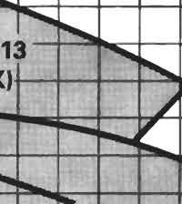
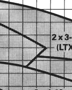
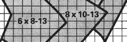


5 Turbomachinery 79 Fig Pump Selection Chart, From Goulds Pump Company.
6 80 Mechanical Equipment and Systems Fig. 4.3a - Typical Centrifugal Pump Performance Curves, From Goulds Pump Company.


7 Turbomachinery 81 Fig. 4.3b - Typical Centrifugal Pump Performance Curves, From Goulds Pump Company.
8 82 Mechanical Equipment and Systems Fig. 4.3c - Typical Centrifugal Pump Performance Curves, From Goulds Pump Company.
9 Turbomachinery 83 Fig. 4.3d - Typical Centrifugal Pump Performance Curves, From Goulds Pump Company.


10 84 Mechanical Equipment and Systems Fig. 4.3e - Typical Centrifugal Pump Performance Curves, From Goulds Pump Company.
11 Turbomachinery 85 Pumps and fans are chosen to meet the special requirements of a particular system. In any given system, the operating point of a pump or fan is determined by comparing the system performance curve or pressure loss characteristic to the system performance curve of the prime mover. Given a pump or fan characteristic which is usually of a polynomial form: p p = a o + a 1 ṁ + a 2 ṁ a n ṁ n (4.4) and the following system characteristic which may be fitted to a polynomial or may be in the form of an actual mathematical model (in which case it will not be a polynomial): p s = b o + b 1 ṁ + b 2 ṁ b n ṁ n (4.5) Fig Matching Pump and System Characteristics, From Fluid Mechanics, White, McGraw-Hill, The operating point occurs when the pump or fan pressure drop equals the system pressure drop: which yields p p = p s (4.6) or a o + a 1 ṁ + a 2 ṁ a n ṁ n = b o + b 1 ṁ + b 2 ṁ b n ṁ n (4.7) (a o b o ) + (a 1 b 1 )ṁ + (a 2 b 2 )ṁ (a n b n )ṁ n = f(ṁ) = 0 (4.8)
12 86 Mechanical Equipment and Systems This equation is a non-linear expression which requires the root, ṁ, to be determined. This type of equation is easily solved using a Newton-Raphson root finding procedure, or easily dealt with using most computer software. For a Newton-Raphson procedure one applies the following equation repeatedly until convergence is acheived: x i+1 = x i f(x i) f (x i ) (4.9) where x i the value of the solution variable for the i th iteration, and x 0 denotes an initial guess. Provided a reasonable initial guess is made, Newton-Raphson iteration converges after two to three iterations. Thus if x i = ṁ, we may write ṁ i+1 = ṁ i (a o b o ) + (a 1 b 1 )ṁ i + (a 2 b 2 )ṁ 2 i + + (a n b n )ṁ n i (a 1 b 1 ) + 2(a 2 b 2 )ṁ i + + n(a n b n )ṁ n 1 i (4.10) where ṁ i is an initial guess. The procedure may then be repeated with ṁ i = ṁ i+1 until desired convergence is achieved. When dealing with polynomial forms, one must be careful as multiple roots often exist. These may be real and/or complex and the correct solution is the only real positive root. However, there are some situations when dealing with systems of multiple fans, in which multiple positive real roots are obtained, i.e. multiple operating points. This can lead to some operational instabilities. This is a result of the peculier fan curves that often result Components in Series Pumps and fans are often arranged in series for a high impedance system, i.e. a system which has a high head characteristic. Pumps or fans may be combined in series to provide the necessary head required in a high impedance system when the discharge characteristics are satisfactory but the head characteristics are not. In a series configuration, the discharge from one pump or fan is fed into the intake of the second pump or fan. The rule for combining components in series is that the two heads are summed at constant discharge rate. This leads to a new operating curve for the combined system. In general, given two or more pump or fan curves, the equivalent series system curve is given by: H s = H 1 + H 2 + H n (4.11)
13 Turbomachinery 87 Fig Combining Pumps or Fans in Series, From Fluid Mechanics, White, McGraw-Hill, Components in Parallel Pumps and fans may also be combined in parallel. A parallel arrangement is used in a low impedance system, that is, a system which has a low head characteristic. Pumps or fans are used in parallel when the head characteristics are adequate, but the discharge characteristics are not. The rule for combining pumps or fans in parallel is that the discharge is summed at constant head. Pumps combined in parallel must be run with care if the operating characteristics are very different. When dissimilar pumps are combined in parallel, the pump with the lower head characteristic cannot be operated until the head in the larger pump has decreased to that of the smaller pump. In general, given two or more pump or fan curves, the equivalent parallel system curve is given by: Q p = Q 1 (H) + Q 2 (H) + Q n (H) (4.12)
14 88 Mechanical Equipment and Systems Fig Combining Pumps or Fans in Parallel, From Fluid Mechanics, White, McGraw-Hill, Cavitation in Pumps Cavitation in pumps occurs when the pressure at any point inside the pump falls below the vapour pressure of the liquid. At this point the liquid vaporizes and the bubbles are carried through the pump. If at any point the pressure increases above the vapour pressure, the bubbles collapse. This collapsing of bubbles can lead to mechanical wear in the form of pitting. This phenomena is known as caviation. Cavitation in pumps usually occurs on the inlet side of pumps where suction or low (negative gage) pressures are found. In order to prevent cavitation from occurring, the pressure anywhere inside the pump must be higher than the vapour pressure of the working liquid. To prevent cavitation from occurring, a new parameter referred to as the Net Positive Suction Head (NPSH) is defined. It is defined as the difference between the head at the pump inlet and the vapour pressure head: NP SH A = p i ρg + V i 2 2g p v ρg (4.13) We may rewrite the expression for NPSH in terms of the location Z i above the surface fluid reservoir whose pressure is at p a, using Bernoulli s equation to obtain: NP SH A = p a ρg Z i h f,i p v ρg (4.14) where the h f,i term represents the headloss incurred between the surface of the reservoir and the pump inlet. The parameter Z i as we shall see, may be positive or negative. If it is negative, the pump must be placed below the free surface of the reservoir from which the pump is drawing fluid. All pump performance curves contain a plot of the NP SH that is required to avoid cavitation, denoted as NP SH R. When matching a pump to a system, the NP SH A
15 Turbomachinery 89 (available), i.e. the right hand side of Eq. (4.15), must be greater than the NP SH R (required) on the pump performance plot. We usually denote this requirement as: NP SH A > NP SH R (4.15) By comparing NP SH R with the expression for NP SH A, we may solve for pump elevation Z i or inlet headlosses h f,i which ensures cavitation will not occur. In general, we may encounter three typical problems involving cavitation prevention: vertical placement, i.e. find Z i horizontal placement, i.e. find L i from h fi size a valve, i.e. find K v from h fi 4.5 Fans Fans are used to move gases from one region to another without an appreciable change in density. Fans must overcome losses in a system due to friction in ducting, minor losses due to fittings, and flow through components such as filters, cleaners, etc. Fans usually fall into the following classes: centrifugal axial flow special design or application. Depending upon the application, fans come in many sizes. Small fans, sometimes called muffin fans, are used to cool electronics components, cabinets, and other assemblies. These types of fans are often an axial flow design, and may push or pull the air through the system. In larger cooling systems or in building HVAC systems, fans may be several orders of magnitude larger and have great capacity. Proper fan selection is important in systems for achieving desired flow and desired noise levels.
16 90 Mechanical Equipment and Systems Fig A Centrifugal Fan, From ASHRAE Handbook Operational Aspects of Fans Fan performance is reported in a similar fashion as pump performance. However, on many fan curves used in HVAC systems, the following information is provided: and Total Pressure P t vs Flow Static Pressure P s vs Flow Total Efficiency η t vs Flow Static Efficiency η s vs Flow Power Requirement The total and static fan efficiencies are defined as follows: η t = ṁ(p t1 P t2 ) ρẇsh η s = ṁ(p s1 P s2 ) ρẇsh (4.16) (4.17) When matching fan/system characteristics care must be take to work with the appropriate fan curve. If the inlet and exit areas of the fan are not equal then the total pressure curve must be used. If it is not given, then it must be generated using knowledge of the static fan curve, the discharge, and the exit area. This is done using:
17 Turbomachinery 91 P t = P s + ρv 2 (4.18) 2 For equal inlet and exit areas the static and total pressure curves are equal. This is most often the case with pumps but not with fans. In general when working with axial flow fans, this is not an issue as the inlet and exit areas are nearly identical, and hence only static pressure is required. Since fan pressures are much lower than those of liquids, it is usually reported in terms of inches of water or mm of water. Thus, when working with fan curves care must be taken to convert the fan curve to match the pressure losses which assume air as the working fluid, or to convert the losses into inches or mm of water. To make this conversion in SI units the following is required: p [mmh 2 O] = p [P a] g (4.19) Fig A Typical Centrifugal Fan Curve, From ASHRAE Handbook. Fans may be operated in series or parallel as are pumps for the same reasons. In a number of applications such as electronics cooling it may be easier to work with the system on a per fan basis. Thus if a heat sink requires more than one axial flow fan to direct air flow between fins, it is often easier to consider only a single fan and a system control volume for the portion of the heat sink or electronic enclosure covered by the fan. On the other hand, we may combine the fan characteristics for all fans and consider the entire heat sink or enclosure as the system control volume. Air flow in HVAC systems is most often controlled using a variable flow method based on damper and speed control. This allows for precise management of air distribution in these systems. In many HVAC systems an important consideration is what is often referred to as the system effect. The system effect accounts for the fact that the system curves are based on the assumption of uniform velocity profiles
18 92 Mechanical Equipment and Systems in ducting and at the exits of fans. However, as a result of the complex nature of the flow through a fan into a duct, there may be a required minimum length to allow for flow development. This additional effect influences both the fan curve and the system curve by lowering the actual fan curve and raising the system curve, resulting in a reduced discharge. This is evident in the Laboratory setup used in this course. To minimize this problem, one should consider providing a reasonable length for flow development as recommended by the HVAC guidlines most often found in the ASHRAE guide, and to match the fan exit area and duct inlet area such that the ratio of these areas is between 85% < A f /A d < 110%. Also, the transitioning for these sections should not exceed 15 degrees for converging sections and 7 degrees for diverging sections Fan Selection Fans are selected to deliver the necessary flow and pressure drop characteristics. In addition, the type of fan (centrifugal or axial flow) is also selected based on application. Refer to the handout for more information on operational and application realated issues pertaining to fan selection. 4.6 Similarity Laws for Pumps and Fans The use of dimensionless performance variables for pumps and fans is desirable in a systems analysis. This allows for greater flexibility in the use of pump or fan performance data. Pump or fan performance in general, is a function of several variables: ( φ Ẇ, ω, D, Q, H, ρ, µ, l 1 D, l ) 2 D,... = 0 (4.20) where l i represent other dimensions of the turbomachine. For geometrically similar machines where all dimensions are scaled proportionally, only the diameter of the impeller becomes critical, and we may write: φ(ẇ, ω, D, Q, H, ρ, µ) = 0 (4.21) Using dimensional analysis it can be shown that the following dimensionless relationships may be obtained to characterize turbomachine performance for incompressible fluids: C w = C p = Ẇ ρ(ωd) 3 D 2 (4.22) p ρ(ωd) 2 (4.23)
19 Turbomachinery 93 C Q = Q (ωd)d 2 (4.24) where C w, C p, C Q are the power coefficient, pressure coefficient, and discharge coefficient, respectively, for the turbomachine. Further, we may write the pressure coefficient as: C H = Hg (ωd) 2 (4.25) Finally, the Reynolds number for the turbomachine may be defined as: Re D = ρ(ωd)d µ (4.26) The turbomachine efficiency may also be defined in terms of these dimensionless groups. It is not difficult to show that: η = C QC H C W (4.27) We use these affinity or similarity laws to scale pump or fan performance curves for families of similar machines. However, caution must be excerised when applying these relationships. It is not a simple matter to equate the dimensionless coefficients for similar machines. We see from the relationships above that ωd appears as a group. This is the characteristic rotor or blade tip speed. The remaining parameter appears as a product D 2, which is proportional to area. Thus, if the pump housing is not scaled proportionally, that is only the impeller is scaled, this group may be interpreted as being proportional to a characteristic flow area, Shepherd (1964). This leads to very different scaling laws. For example, for geometrically similar machines we may write: Ẇ 2 Ẇ 1 = ( ρ2 H 2 H 1 = ρ 1 Q 2 Q 1 = ) ( ) 3 ( ) 5 ω2 D2 (4.28) ( ω2 ω 1 ( ω2 ω 1 ω 1 D 1 ) 2 ( ) 2 D2 (4.29) D 1 ) ( ) 3 D2 (4.30) These are the scaling laws reported in virtually all fluids texts and most introductory turbomachine texts. However, in the case of only an impeller change, the turbomachines are no longer geometrically similar machines. This type of scaling occurs quite frequently and needs to be properly addressed. Using the above laws, we may still write: D 1
20 94 Mechanical Equipment and Systems Ẇ 2 Ẇ 1 = ( ρ2 ρ 1 ) ( ) 3 ( ω2 D2 ω 1 Q 2 Q 1 = ( ω2 ω 1 D 1 H 2 ) 3 ( ) 2 D2 i = H 1 ) ( ) D2 D 1 D 1 ( ω2 h = ( ρ2 ω 1 D 1 ( ) 2 D2 i ρ 1 ) ( ) 3 ( ) 3 ω2 D2 (4.31) ω 1 D 1 ) 2 ( ) 2 D2 (4.32) D 1 h = ( ω2 ω 1 ) ( ) D2 D 1 (4.33) Here, i denotes the impeller and h denotes the housing. We then see that for the same housing, the ratio (D 2 /D 1 ) h is unity. This leads to very different proportionality or scaling laws. In a number of cases it is more practical to change the characteristic of a pump by changing only the impeller size over a moderate range of operation variables for a fixed pump speed. In this way a manufacturer does not have to design a new housing for each different pump of different capacity over a nominal range of operating conditions. It is not always clear whether a manufacturer s pump performance curves for a family of pumps, are for geometrically similar pumps or for partially similar machines. This will be left as an excerise in the problem sets to verify for a give set of curves. We generally apply these scaling laws within families of similar machines or to examine the effect of a change in one or more operating variables, such as the effect of pump speed or working fluid. The latter is quite important, as many pumps are tested using water, but many applications use other fluids with very different properties. Unfortunately, pump efficiency, does not scale well according the relationships given above. However, it has been observed that 1 η 2 1 η 1 ( D1 D 2 ) n (4.34) where n is found to vary somewhat, but is close to a single value of n = 1/4. This is sufficient to obtain a reasonable estimate. 4.7 Flow Control Often, the resultant flow in a system may not meet design requirements, or depending upon system demand, a variable flow may be desired. Flow control in a system can be achieved in a number of ways. These include: valve or damper control, i.e. change the system curve speed control, i.e. change the pump or fan curve speed and damper/valve control, i.e. manage both curves

21 Turbomachinery 95 The use of valve or damper control allows the system curve to shifted to the left or right by means of a variable resistance or K factor. This leads to a decrease or an increase in flow while the prime mover rotates at a fixed speed. The use of variable speed allows the prime mover curve to be shifted up or down and hence increasing or decreasing the flow in the system with a fixed system curve. Finally, the use of both speed and valve/damper control allows more flexibility in the operation of a system. This mode of operation is the most efficient from a cost point of view. Fig Flow Control, From Marks Mechanical Engineering Handbook. 4.8 Compressors Compressors move gases in systems where an appreciable change in gas density occurs. Compressors are found in many applications, such as refrigeration systems, gas processing and storage, and pneumatic systems to name a few. Compressors are classified according to: centrifugal positive displacement (reciprocating) axial flow
22 96 Mechanical Equipment and Systems Fig Compressor Classification Ideal Compressor Theory Most compressor problems involve determining the power required to compress a certain volume of gas at one particular to another state. Compression can be achieved in a number of ways. Assuming a polytropic process, that is pv n = C (4.35) we may compress a gas isothermally n = 1, isentropically n = k = C p /C v and polytropically n k. We will consider this in more detail and also consider compressor performance. The most common type of compressor is the reciprocating piston type, while axial flow compressors are found in gas turbine systems. Ideal compressor theory may be applied with the following assumptions: polytropic constant n is the same for compression/expansion heat transfer is negligible The ideal compression cycle gives: Evaluating gives: h 2 h 1 = 2 1 vdp = 2 1 ( ) n C dp (4.36) p
23 Turbomachinery 97 h 2 h 1 = nc1/n n 1 h 2 h 1 = C ln ( p2 [ ] p (n 1)/n 2 p (n 1)/n 1, n 1 p 1 Combining with the ideal gas law, i.e. ), n = 1 (4.37) pv = RT (4.38) and using k = C p /C v and R = C p C v, we obtain the temperature ratio across the compressor: ( ) ( ) T 2 k 1 n [r = (n 1)/n 1 ] + 1, n 1 T 1 k n 1 T 2 T 1 = ( k 1 k ) ln r + 1, n = 1 (4.39) where r = p 2 /p 1 is the compression ratio. The value of n has two special cases. For an isentropic process s 2 = s 1, n = k, while for an isothermal process T 2 = T 1, n = 1. Fig Simple Compression Cycle, From Burmeister (1995). Compressor Work and Efficiency The work done by a compressor is obtained from the enthalpy balance on the gas flowing through it, Ẇ c = ṁc p (T 2 T 1 ) (4.40) Using the appropriate relationships we may obtain the following results for the compressor work:
24 98 Mechanical Equipment and Systems ( ) ( ) k 1 n [r Ẇ c = ṁc p T (n 1)/n 1 1 ] 1, n 1 k n 1 ( ) k 1 Ẇ c = ṁc p T 1 ln r, n = 1 k (4.41) The isentropic efficiency is defined as: η s = ṁc p(t 2,s T 1 ) ṁc p (T 2 T 1 ) = r(k 1)/k 1 T 2 /T 1 1 (4.42) The overall or mechanical compressor effciency is defined as: η m = ṁc p(t 2 T 1 ) Ẇ shaft (4.43) We may now examine two possible routes to compression, isothermal compression and isentropic compression. For the two processes, it can be shown that the ratio of compression work for isothermal compression to compression work for isentropic compression is: Ẇ c,t = k 1 ln r Ẇ c,s k r (k 1)/k 1 (4.44) Examination of this result reveals that less work is required to compress a gas isothermally. In practice this may be difficult to achieve, however through multistage compression with intercooling, it is possible to produce a more efficient compression process. After each stage of compression, heat is removed from the gas, ideally returning it to its original inlet temperature T 1. Intercoolers are usually water cooled heat exchangers. Intercooling is usually incorporated if the the discharge temperature reach 300 F.
 4.8.2 Compressor Selection and Performance We conclude with a discussion of two important compressor performance issues: surge and choking.")
25 Turbomachinery 99 Fig A Multi-stage Compression Cycle, From Burmeister (1995). In a multistaged compression process the mechanical efficiency may be written as: N η m = i=1 Ẇ cycle Ẇ shaft (4.45) Compressor Selection and Performance We conclude with a discussion of two important compressor performance issues: surge and choking. On a given compressor performance plot which usually gives the pressure versus mass or volumetric flow, there are two lines which connect performance curves at low flows and high flows. These are the surge line and the choke line. These are illustrated in Fig. 13. The point of minimum flow/maximum pressure where the developed pressure is insuffucient to overcome the system resistance, is referred to as surge. When surge occurs, gas in discharge piping flows back into the compressor. With no discharge flow, discharge pressure drops and the cycle repeats itself. Surging can cause compressors to overheat. The point of maximum flow/minumum pressure is referred to as the choke line. Choking occurs when the gas reaches the sonic velocity at any point in the compressor. When this is achieved, flow through the compressor can not increase unless the compressor is modified.
26 100 Mechanical Equipment and Systems Finally, compressor discharge on performance plots may be given in either actual cubic feet per minute (ACFM), i.e. at process conditions, or in standard cubic feet per minute (SCFM), i.e. at 60 F and 14.7 psi. Care must be taken to understand which reference is used. If flow is given in SCFM, then conversion to actual conditions must be made. Compressors are chosen based on compression ratio and discharge. Fig. 14 provides a typical compressor selection chart. Fig Simple Compressor Performance Curve.
27 Turbomachinery 101 Fig Compressor Selection Chart.
28 102 Mechanical Equipment and Systems References Balje, O.E., Turbomachines, Wiley, 1981, New York, NY. Csanady, G.T., Theory of Turbomachines, McGraw-Hill, 1964, New York, NY. Dixon, S.L., Fluid Mechanics, Thermodynamics of Turbomachinery, Pergamon Press, 1975, Oxford, UK. Logan, E., Turbomachinery, Marcel Dekker, Inc., 1993, New York, NY. Mironer, A., Engineering Fluid Mechanics, McGraw-Hill, 1979, New York, NY. Shepherd, D., Principles of Turbomachinery, Wiley, 1964, New York, NY. Wilson, D.G. and Korakianitis, T., The Design of High-Efficiency Turbomachinery and Gas Turbines, Prentice Hall, 1998, Upper Saddle River, NJ. White, F.M., Fluid Mechanics, McGraw-Hill, 2000, New York, NY. Wright, T., Fluid Machinery, CRC Press, 1999, Boca Raton, FL.
29 Turbomachinery 103 PROBLEMS Problem 4.1 A piping system requires a pump to be selected to deliver at least 75 gpm of flow at 400 ft of head. The pump is to operate on a 60 Hz fixed nominal speed of 3500 RPM. Select a pump using Fig. 4.2 and determine the nominal impeller size, operating efficiency, and NP SH R for the desired characteristics. Problem 4.2 Given a pump curve of the form: H p = ṁ 2 and system curve of the following form: H f = ṁ + 0.5ṁ 2 find the system operating point. Problem 4.3 Consider a CPU cooler consists of a fan (299 DS from handout) and a heat sink. The sink and fan are configured such that impinging air flow is directed at the base of the sink and ducted outwards into two parallel flow paths. If the sink is 9 [cm] by 9 [cm] square and contains 11 fins of thickness 2 [mm] and height 2 [cm], determine the approximate channel air velocity available for cooling the fins and hence the CPU. In the solution, approximate the fan performance curve as a linear. Problem 4.4 Consider a pump with the following performance characteristic: p = 100, ṁ 2 Find the equivalent characteristic for two pumps in series (2PS) and two pumps in parallel (2PP). Problem 4.5 Consider the closed loop pumping system sketched in class. If the total length of piping is 60 [m], with a diameter of 5 [cm], and a roughness ɛ = [m], what is the resultant flow in the system if the pump has the following characteristic:
30 104 Mechanical Equipment and Systems H p = ṁ 2 and the filter has the following pressure loss: H f = ṁ 2 If the desired discharge were ṁ = 25 [kg/s] and the pump was normally run at 1750 RPM, can the desired discharge be achieved with two pumps in series or two pumps in parallel. Problem 4.6 Reconsider Example 4.5. Do one or two pumps in series or parallel operating at twice the speed provide the desired demand of ṁ = 25 [kg/s]. Problem 4.7 A particular pump is required to pump 24,000 [gpm] of water whose free surface is at 1 [atm]. If the losses in the system up to the inlet of the pump are determined to be 6 [ft] of water, where should the pump be placed to avoid cavitation if NP SH R = 40 [ft]. Problem 4.8 In Example 4.5, if the required NPSH is given by: NP SH R = ṁ 2 determine where the pump should be placed in the system if there is 20 [m] of piping leading to the pump inlet. Include minor losses in the analysis. If the system were designed with the valve at 50 percent open, is cavitation more likely to occur when the valve is opened further or closed further. Justify your answer by performing a calculation with K v = 3 and K v = 9 Problem 4.9 Consider two pumps having the same housing but different impellers. The following data were obtained for the two pumps: 13 inch Impeller H = 188, 184, 181, 175, 165, 152, 132, 111 Q = 0, 125, 175, 225, 275, 325, 375, 425
31 Turbomachinery inch Impeller H = 87, 86, 84, 81, 77, 72, 67, 62 Q = 0, 100, 125, 150, 175, 200, 225, 250 Show using the pump affinity laws that either the 13 or 9 data can be scaled such that a single curve is obtained for both impellers. Problem 4.10 For a given pump show the effect of a change in working fluid density, assuming that viscosity is not much different than that of water. Consider two cases: constant power and constant speed.
Department of Energy Fundamentals Handbook. THERMODYNAMICS, HEAT TRANSFER, AND FLUID FLOW, Module 3 Fluid Flow
 Department of Energy Fundamentals Handbook THERMODYNAMICS, HEAT TRANSFER, AND FLUID FLOW, Module 3 REFERENCES REFERENCES Streeter, Victor L., Fluid Mechanics, 5th Edition, McGraw-Hill, New York, ISBN 07-062191-9.
Introduction to Turbomachinery
 1. Coordinate System Introduction to Turbomachinery Since there are stationary and rotating blades in turbomachines, they tend to form a cylindrical form, represented in three directions; 1. Axial 2. Radial
Applied Fluid Mechanics
 Applied Fluid Mechanics 1. The Nature of Fluid and the Study of Fluid Mechanics 2. Viscosity of Fluid 3. Pressure Measurement 4. Forces Due to Static Fluid 5. Buoyancy and Stability 6. Flow of Fluid and
9. Pumps (compressors & turbines) Partly based on Chapter 10 of the De Nevers textbook.
 Partly based on Chapter 10 of the De Nevers textbook.") Lecture Notes CHE 31 Fluid Mechanics (Fall 010) 9. Pumps (compressors & turbines) Partly based on Chapter 10 of the De Nevers textbook. Basics (pressure head, efficiency, working point, stability) Pumps
Lecture Notes CHE 31 Fluid Mechanics (Fall 010) 9. Pumps (compressors & turbines) Partly based on Chapter 10 of the De Nevers textbook. Basics (pressure head, efficiency, working point, stability) Pumps
Contents. 1 Introduction to Gas-Turbine Engines Overview of Turbomachinery Nomenclature...9
 Preface page xv 1 Introduction to Gas-Turbine Engines...1 Definition 1 Advantages of Gas-Turbine Engines 1 Applications of Gas-Turbine Engines 3 The Gas Generator 3 Air Intake and Inlet Flow Passage 3
CHAPTER EIGHT P U M P I N G O F L I Q U I D S
 CHAPTER EIGHT P U M P I N G O F L I Q U I D S Pupmps are devices for supplying energy or head to a flowing liquid in order to overcome head losses due to friction and also if necessary, to raise liquid
Chapter Four Hydraulic Machines
 Contents 1- Introduction. 2- Pumps. Chapter Four Hydraulic Machines (لفرع الميكانيك العام فقط ( Turbines. -3 4- Cavitation in hydraulic machines. 5- Examples. 6- Problems; sheet No. 4 (Pumps) 7- Problems;
Department of Civil and Environmental Engineering CVNG 1001: Mechanics of Fluids
 INTRODUCTION Hydrodynamic Machines A hydromachine is a device used either for extracting energy from a fluid or to add energy to a fluid. There are many types of hydromachines and Figure 1 below illustrates
Chapter Four Hydraulic Machines
 Contents 1- Introduction. - Pumps. Chapter Four Hydraulic Machines (لفرع الميكانيك العام فقط ( Turbines. -3 4- Cavitation in hydraulic machines. 5- Examples. 6- Problems; sheet No. 4 (Pumps) 7- Problems;
Introduction to Fluid Machines, and Compressible Flow Prof. S. K. Som Department of Mechanical Engineering Indian Institute of Technology, Kharagpur
 Introduction to Fluid Machines, and Compressible Flow Prof. S. K. Som Department of Mechanical Engineering Indian Institute of Technology, Kharagpur Lecture - 09 Introduction to Reaction Type of Hydraulic
TOTAL HEAD, N.P.S.H. AND OTHER CALCULATION EXAMPLES Jacques Chaurette p. eng., June 2003
 TOTAL HEAD, N.P.S.H. AND OTHER CALCULATION EXAMPLES Jacques Chaurette p. eng., www.lightmypump.com June 2003 Figure 1 Calculation example flow schematic. Situation Water at 150 F is to be pumped from a
Chapter Four fluid flow mass, energy, Bernoulli and momentum
 4-1Conservation of Mass Principle Consider a control volume of arbitrary shape, as shown in Fig (4-1). Figure (4-1): the differential control volume and differential control volume (Total mass entering
M E 320 Professor John M. Cimbala Lecture 23
 M E 320 Professor John M. Cimbala Lecture 23 Today, we will: Discuss diffusers and do an example problem Begin discussing pumps, and how they are analyzed in pipe flow systems D. Diffusers 1. Introduction.
Turbomachinery. Hasan Ozcan Assistant Professor. Mechanical Engineering Department Faculty of Engineering Karabuk University
 Turbomachinery Hasan Ozcan Assistant Professor Mechanical Engineering Department Faculty of Engineering Karabuk University Introduction Hasan Ozcan, Ph.D, (Assistant Professor) B.Sc :Erciyes University,
Thermodynamics: An Engineering Approach Seventh Edition Yunus A. Cengel, Michael A. Boles McGraw-Hill, Chapter 7 ENTROPY
 Thermodynamics: An Engineering Approach Seventh Edition Yunus A. Cengel, Michael A. Boles McGraw-Hill, 2011 Chapter 7 ENTROPY Copyright The McGraw-Hill Companies, Inc. Permission required for reproduction
Contents. 2 Basic Components Aerofoils Force Generation Performance Parameters xvii
 Contents 1 Working Principles... 1 1.1 Definition of a Turbomachine... 1 1.2 Examples of Axial Turbomachines... 2 1.2.1 Axial Hydraulic Turbine... 2 1.2.2 Axial Pump... 4 1.3 Mean Line Analysis... 5 1.4
CIVE HYDRAULIC ENGINEERING PART II Pierre Julien Colorado State University
 1 CIVE 401 - HYDRAULIC ENGINEERING PART II Pierre Julien Colorado State University Problems with and are considered moderate and those with are the longest and most difficult. In 2018 solve the problems
Lesson 6 Review of fundamentals: Fluid flow
 Lesson 6 Review of fundamentals: Fluid flow The specific objective of this lesson is to conduct a brief review of the fundamentals of fluid flow and present: A general equation for conservation of mass
Pressure and Flow Characteristics
 Pressure and Flow Characteristics Continuing Education from the American Society of Plumbing Engineers August 2015 ASPE.ORG/ReadLearnEarn CEU 226 READ, LEARN, EARN Note: In determining your answers to
Thermodynamics: An Engineering Approach Seventh Edition in SI Units Yunus A. Cengel, Michael A. Boles McGraw-Hill, 2011.
 Thermodynamics: An Engineering Approach Seventh Edition in SI Units Yunus A. Cengel, Michael A. Boles McGraw-Hill, 2011 Chapter 7 ENTROPY Mehmet Kanoglu University of Gaziantep Copyright The McGraw-Hill
ENTROPY. Chapter 7. Mehmet Kanoglu. Thermodynamics: An Engineering Approach, 6 th Edition. Yunus A. Cengel, Michael A. Boles.
 Thermodynamics: An Engineering Approach, 6 th Edition Yunus A. Cengel, Michael A. Boles McGraw-Hill, 2008 Chapter 7 ENTROPY Mehmet Kanoglu Copyright The McGraw-Hill Companies, Inc. Permission required
COURSE CODE : 3072 COURSE CATEGORY : B PERIODS/ WEEK : 5 PERIODS/ SEMESTER : 75 CREDIT : 5 TIME SCHEDULE
 COURSE TITLE : FLUID MECHANICS COURSE CODE : 307 COURSE CATEGORY : B PERIODS/ WEEK : 5 PERIODS/ SEMESTER : 75 CREDIT : 5 TIME SCHEDULE MODULE TOPIC PERIOD 1 Properties of Fluids 0 Fluid Friction and Flow
10 minutes reading time is allowed for this paper.
 EGT1 ENGINEERING TRIPOS PART IB Tuesday 31 May 2016 2 to 4 Paper 4 THERMOFLUID MECHANICS Answer not more than four questions. Answer not more than two questions from each section. All questions carry the
Objectives. Conservation of mass principle: Mass Equation The Bernoulli equation Conservation of energy principle: Energy equation
 Objectives Conservation of mass principle: Mass Equation The Bernoulli equation Conservation of energy principle: Energy equation Conservation of Mass Conservation of Mass Mass, like energy, is a conserved
CENTRIFUGAL PUMP SELECTION, SIZING, AND INTERPRETATION OF PERFORMANCE CURVES
 CENTRIFUGAL PUMP SELECTION, SIZING, AND INTERPRETATION OF PERFORMANCE CURVES 4.0 PUMP CLASSES Pumps may be classified in two general types, dynamic and positive displacement. Positive displacement pumps
Two mark questions and answers UNIT I BASIC CONCEPT AND FIRST LAW SVCET
 Two mark questions and answers UNIT I BASIC CONCEPT AND FIRST LAW 1. What do you understand by pure substance? A pure substance is defined as one that is homogeneous and invariable in chemical composition
CHAPTER TWO CENTRIFUGAL PUMPS 2.1 Energy Transfer In Turbo Machines
 7 CHAPTER TWO CENTRIFUGAL PUMPS 21 Energy Transfer In Turbo Machines Fig21 Now consider a turbomachine (pump or turbine) the total head (H) supplied by it is The power delivered to/by the fluid simply
Introduction to Fluid Machines and Compressible Flow Prof. S. K. Som Department of Mechanical Engineering Indian Institute of Technology, Kharagpur
 Introduction to Fluid Machines and Compressible Flow Prof. S. K. Som Department of Mechanical Engineering Indian Institute of Technology, Kharagpur Lecture - 1 Introduction to Fluid Machines Well, good
Piping Systems and Flow Analysis (Chapter 3)
") Piping Systems and Flow Analysis (Chapter 3) 2 Learning Outcomes (Chapter 3) Losses in Piping Systems Major losses Minor losses Pipe Networks Pipes in series Pipes in parallel Manifolds and Distribution
Piping Systems and Flow Analysis (Chapter 3) 2 Learning Outcomes (Chapter 3) Losses in Piping Systems Major losses Minor losses Pipe Networks Pipes in series Pipes in parallel Manifolds and Distribution
Theory of turbo machine Effect of Blade Configuration on Characteristics of Centrifugal machines. Unit 2 (Potters & Wiggert Sec
 Theory of turbo machine Effect of Blade Configuration on Characteristics of Centrifugal machines Unit (Potters & Wiggert Sec. 1..1, &-607) Expression relating Q, H, P developed by Rotary machines Rotary
CALIFORNIA POLYTECHNIC STATE UNIVERSITY Mechanical Engineering Department ME 347, Fluid Mechanics II, Winter 2018
 CALIFORNIA POLYTECHNIC STATE UNIVERSITY Mechanical Engineering Department ME 347, Fluid Mechanics II, Winter 2018 Date Day Subject Read HW Sept. 21 F Introduction 1, 2 24 M Finite control volume analysis
PROBABILISTIC APPROACH TO DETERMINE PUMP OPERATING POINT
 Technical Paper Session: 16 1 Session Name: Performing pump systems PROBABILISTIC APPROACH TO DETERMINE PUMP OPERATING POINT Author: Dr. Swaminathan Gopalakrishnan General Manager CAC ELGI Equipments Ltd.
vector H. If O is the point about which moments are desired, the angular moment about O is given:
 The angular momentum A control volume analysis can be applied to the angular momentum, by letting B equal to angularmomentum vector H. If O is the point about which moments are desired, the angular moment
PUMP SYSTEM ANALYSIS AND SIZING. BY JACQUES CHAURETTE p. eng.
 PUMP SYSTEM ANALYSIS AND SIZING BY JACQUES CHAURETTE p. eng. 5 th Edition February 2003 Published by Fluide Design Inc. www.fluidedesign.com Copyright 1994 I TABLE OF CONTENTS Introduction Symbols Chapter
Prof. Dr.-Ing. F.-K. Benra. ISE batchelor course
 University Duisburg-Essen Campus Duisburg Faculty of engineering Science Department of Mechanical Engineering Examination: Fluid Machines Examiner: Prof. Dr.-Ing. F.-K. Benra Date of examination: 06.03.2006
SHORTCUT CALCULATIONS AND GRAPHICAL COMPRESSOR SELECTION PROCEDURES
 APPENDIX B SHORTCUT CALCULATIONS AND GRAPHICAL COMPRESSOR SELECTION PROCEDURES B.1 SELECTION GUIDE FOR ELLIOTT MULTISTAGE CENTRIFUGAL COMPRESSORS* * Reprinted from a 1994 Elliott Company sales bulletin.
Estimation of Power Consumption by Centrifugal Pump with Reduced Impeller Size
 Estimation of Power Consumption by Centrifugal Pump with Reduced Impeller Size Somchart Chantasiriwan Faculty of Engineering, Thammasat University, Pathum Thani 111, Thailand Correspondence: Somchart Chantasiriwan
Chapter Two. Basic Thermodynamics, Fluid Mechanics: Definitions of Efficiency. Laith Batarseh
 Chapter Two Basic Thermodynamics, Fluid Mechanics: Definitions of Efficiency Laith Batarseh The equation of continuity Most analyses in this book are limited to one-dimensional steady flows where the velocity
BME-A PREVIOUS YEAR QUESTIONS
 BME-A PREVIOUS YEAR QUESTIONS CREDITS CHANGE ACCHA HAI TEAM UNIT-1 Introduction: Introduction to Thermodynamics, Concepts of systems, control volume, state, properties, equilibrium, quasi-static process,
Dr. S. Ramachandran Prof. R. Devaraj. Mr. YVS. Karthick AIR WALK PUBLICATIONS
 Fluid Machinery As per Revised Syllabus of Leading Universities including APJ ABDUL KALAM TECHNOLOGICAL UNIVERSITY Dr. S. Ramachandran Prof. R. Devaraj Professors School of Mechanical Engineering Sathyabama
Centrifugal Machines Table of Contents
 NLNG Course 017 Table of Contents 1 Introduction and Basic Principles... 1.1 Hydraulic Machines... 1.... 1.3 Pump Geometry... 1.4 Pump Blade Geometry...3 1.5 Diffusers...5 1.6 Pump Losses...6 1.7 Example
Chapter 7. Introduction to Fluid Machinery
 Chapter 7 Introduction to Fluid Machinery 1 Classification of Fluid Machines Positive diplacement machines (static type) Turbomachines (dynamic type) Turbines: extract energy to the flow :the fluid does
ME Thermodynamics I
 Homework - Week 01 HW-01 (25 points) Given: 5 Schematic of the solar cell/solar panel Find: 5 Identify the system and the heat/work interactions associated with it. Show the direction of the interactions.
CHAPTER THREE FLUID MECHANICS
 CHAPTER THREE FLUID MECHANICS 3.1. Measurement of Pressure Drop for Flow through Different Geometries 3.. Determination of Operating Characteristics of a Centrifugal Pump 3.3. Energy Losses in Pipes under
Engineering Fluid Mechanics
 Engineering Fluid Mechanics Eighth Edition Clayton T. Crowe WASHINGTON STATE UNIVERSITY, PULLMAN Donald F. Elger UNIVERSITY OF IDAHO, MOSCOW John A. Roberson WASHINGTON STATE UNIVERSITY, PULLMAN WILEY
Thermal & Fluids PE Exam Technical Study Guide Errata
 Thermal & Fluids PE Exam Technical Study Guide Errata This product has been updated to incorporate all changes shown in the comments on the webpage and email comments as of October, 30 2017. If you have
MECA-H-402: Turbomachinery course Axial compressors
 MECA-H-40: Turbomachinery course Axial compressors Pr. Patrick Hendrick Aero-Thermo-Mecanics Year 013-014 Contents List of figures iii 1 Axial compressors 1 1.1 Introduction...............................
INTERNAL FLOWS / FLOWS IN DUCTS
 Fluid and Particulate systems 4451 /018 INTERNAL FLOWS / FLOWS IN DUCTS Ron Zevenhoven ÅA Thermal and Flow Engineering ron.zevenhoven@abo.fi.1 Flow tube sections in series, in parallel, or branched RoNz
Compression and Expansion of Fluids
 CH2303 Chemical Engineering Thermodynamics I Unit V Compression and Expansion of Fluids Dr. M. Subramanian 26-Sep-2011 Associate Professor Department of Chemical Engineering Sri Sivasubramaniya Nadar College
An introduction to thermodynamics applied to Organic Rankine Cycles
 An introduction to thermodynamics applied to Organic Rankine Cycles By : Sylvain Quoilin PhD Student at the University of Liège November 2008 1 Definition of a few thermodynamic variables 1.1 Main thermodynamics
M E 320 Professor John M. Cimbala Lecture 24
 M E 30 Professor John M. Cimbala Lecture 4 Today, we will: Discuss pump performance curves Discuss how to match a pump and a piping system, and do some example problems. Pump Performance a. Pump performance
Determining Liquid Capacity 4 th Annual Pipeline Knowledge Retention Chris Sonneborn November 7, 2013
 Determining Liquid Capacity 4 th Annual Pipeline Knowledge Retention Chris Sonneborn November 7, 2013 Outline What is important? Liquid Properties Thermal Conditions Hydraulic Gradient Flow Regime in Liquids
CLASS Fourth Units (Second part)
") CLASS Fourth Units (Second part) Energy analysis of closed systems Copyright The McGraw-Hill Companies, Inc. Permission required for reproduction or display. MOVING BOUNDARY WORK Moving boundary work (P
CLASS Fourth Units (Second part) Energy analysis of closed systems Copyright The McGraw-Hill Companies, Inc. Permission required for reproduction or display. MOVING BOUNDARY WORK Moving boundary work (P
WATER DISTRIBUTION NETWORKS
 WATER DISTRIBUTION NETWORKS CE 370 1 Components of Water Supply System 2 1 Water Distribution System Water distribution systems are designed to adequately satisfy the water requirements for a combinations
Chapter 7 The Energy Equation
 Chapter 7 The Energy Equation 7.1 Energy, Work, and Power When matter has energy, the matter can be used to do work. A fluid can have several forms of energy. For example a fluid jet has kinetic energy,
Lesson 37 Transmission Of Air In Air Conditioning Ducts
 Lesson 37 Transmission Of Air In Air Conditioning Ducts Version 1 ME, IIT Kharagpur 1 The specific objectives of this chapter are to: 1. Describe an Air Handling Unit (AHU) and its functions (Section 37.1).
CHAPTER 12 Turbomachinery
 CAER urbomachinery Chapter / urbomachinery 800 / 0 8 8 rad /s, u r 8 8 0 0 m /s, u r 8 8 0 0 8 m /s, rbv, but V u since, n n 0 0 0 0 0 0 m / s V V 0 0 m /s, rb 0 0 0 Vn u 0 8 6 77 m /s, tan tan 0 n t V
IJREAS Volume 2, Issue 2 (February 2012) ISSN:
 ISSN:") DESIGN AND CFD ANALYSIS OF SINGLE STAGE, END SUCTION, RADIAL FLOW CENTRIFUGAL PUMP FOR MINE DEWATERING APPLICATION Swapnil Urankar * Dr. H S Shivashankar ** Sourabh Gupta *** ABSTRACT Heavy centrifugal
DESIGN AND CFD ANALYSIS OF SINGLE STAGE, END SUCTION, RADIAL FLOW CENTRIFUGAL PUMP FOR MINE DEWATERING APPLICATION Swapnil Urankar * Dr. H S Shivashankar ** Sourabh Gupta *** ABSTRACT Heavy centrifugal
CHAPTER 5 MASS AND ENERGY ANALYSIS OF CONTROL VOLUMES
 Thermodynamics: An Engineering Approach 8th Edition in SI Units Yunus A. Çengel, Michael A. Boles McGraw-Hill, 2015 CHAPTER 5 MASS AND ENERGY ANALYSIS OF CONTROL VOLUMES Lecture slides by Dr. Fawzi Elfghi
ME332 FLUID MECHANICS LABORATORY (PART II)
") ME332 FLUID MECHANICS LABORATORY (PART II) Mihir Sen Department of Aerospace and Mechanical Engineering University of Notre Dame Notre Dame, IN 46556 Version: April 2, 2002 Contents Unit 5: Momentum transfer
ME332 FLUID MECHANICS LABORATORY (PART II) Mihir Sen Department of Aerospace and Mechanical Engineering University of Notre Dame Notre Dame, IN 46556 Version: April 2, 2002 Contents Unit 5: Momentum transfer
HVAC Clinic. Duct Design
 HVAC Clinic Duct Design Table Of Contents Introduction... 3 Fundamentals Of Duct Design... 3 Pressure Changes In A System... 8 Example 1... 13 Duct Design Methods... 15 Example 2... 15 Introduction The
Prof. Dr.-Ing. F.-K. Benra. ISE Bachelor Course
 University Duisburg-Essen Campus Duisburg Faculty of Engineering Science Department of Mechanical Engineering Name Matr.- Nr. Examination: Fluid Machines Examiner: Prof. Dr.-Ing. F.-K. Benra Date of examination:
TURBOMACHINES. VIJAYAVITHAL BONGALE Associate Professor and Head Department of Mechanical Engineering Malnad College of Engineering, Hassan
 TURBOMACHINES VIJAYAVITHAL BONGALE Associate Professor and Head Department of Mechanical Engineering Malnad College of Engineering, Hassan 573 201. Mobile No:9448821954 E-mail : vvb@mcehassan.ac.in 1 Dimensional
mywbut.com Hydraulic Turbines
 Hydraulic Turbines Hydro-electric power accounts for up to 0% of the world s electrical generation. Hydraulic turbines come in a variety of shapes determined by the available head and a number of sizes
Chapter 5. Mass and Energy Analysis of Control Volumes. by Asst. Prof. Dr.Woranee Paengjuntuek and Asst. Prof. Dr.Worarattana Pattaraprakorn
 Chapter 5 Mass and Energy Analysis of Control Volumes by Asst. Prof. Dr.Woranee Paengjuntuek and Asst. Prof. Dr.Worarattana Pattaraprakorn Reference: Cengel, Yunus A. and Michael A. Boles, Thermodynamics:
ENERGY TRANSFER BETWEEN FLUID AND ROTOR. Dr. Ir. Harinaldi, M.Eng Mechanical Engineering Department Faculty of Engineering University of Indonesia
 ENERGY TRANSFER BETWEEN FLUID AND ROTOR Dr. Ir. Harinaldi, M.Eng Mechanical Engineering Department Faculty of Engineering University of Indonesia Basic Laws and Equations Continuity Equation m m ρ mass
CONTENTS CHAPTER (II) DIMENSIONAL ANALYSIS AND SIMILITUDE OF TURBOMACHINES
 DIMENSIONAL ANALYSIS AND SIMILITUDE OF TURBOMACHINES") CONTENTS CHAPTER (I) BASIC THEORY Historical Review.............. General Introduction............ 4. Velocity Diagram.............. 5.3 Momentum Transfer Principles........ 6.4 Energy Equation..............
CONTENTS CHAPTER (I) BASIC THEORY Historical Review.............. General Introduction............ 4. Velocity Diagram.............. 5.3 Momentum Transfer Principles........ 6.4 Energy Equation..............
Chapter 5. Mass and Energy Analysis of Control Volumes
 Chapter 5 Mass and Energy Analysis of Control Volumes Conservation Principles for Control volumes The conservation of mass and the conservation of energy principles for open systems (or control volumes)
Introduction to Fluid Machines (Lectures 49 to 53)
") Introduction to Fluid Machines (Lectures 49 to 5) Q. Choose the crect answer (i) (ii) (iii) (iv) A hydraulic turbine rotates at N rpm operating under a net head H and having a discharge Q while developing
Introduction to Fluid Machines (Lectures 49 to 5) Q. Choose the crect answer (i) (ii) (iii) (iv) A hydraulic turbine rotates at N rpm operating under a net head H and having a discharge Q while developing
Introduction to Chemical Engineering Thermodynamics. Chapter 7. KFUPM Housam Binous CHE 303
 Introduction to Chemical Engineering Thermodynamics Chapter 7 1 Thermodynamics of flow is based on mass, energy and entropy balances Fluid mechanics encompasses the above balances and conservation of momentum
Pumping Stations Design For Infrastructure Master Program Engineering Faculty-IUG
 umping Stations Design For Infrastructure Master rogram Engineering Faculty-IUG Lecture : umping Hydraulics Dr. Fahid Rabah Water and environment Engineering frabah@iugaza.edu The main items that will
Introduction to Fluid Machines and Compressible Flow Prof. S. K. Som Department of Mechanical Engineering Indian Institute of Technology, Kharagpur
 Introduction to Fluid Machines and Compressible Flow Prof. S. K. Som Department of Mechanical Engineering Indian Institute of Technology, Kharagpur Lecture - 21 Centrifugal Compressor Part I Good morning
where = rate of change of total energy of the system, = rate of heat added to the system, = rate of work done by the system
 The Energy Equation for Control Volumes Recall, the First Law of Thermodynamics: where = rate of change of total energy of the system, = rate of heat added to the system, = rate of work done by the system
COMPUTER AIDED DESIGN OF RADIAL TIPPED CENTRIFUGAL BLOWERS AND FANS
 4 th International Conference on Mechanical Engineering, December 26-28, 21, Dhaka, Bangladesh/pp. IV 55-6 COMPUTER AIDED DESIGN OF RADIAL TIPPED CENTRIFUGAL BLOWERS AND FANS Nitin N. Vibhakar* and S.
ME 309 Fluid Mechanics Fall 2010 Exam 2 1A. 1B.
 Fall 010 Exam 1A. 1B. Fall 010 Exam 1C. Water is flowing through a 180º bend. The inner and outer radii of the bend are 0.75 and 1.5 m, respectively. The velocity profile is approximated as C/r where C
Fachgesprach 12. HVAC Pumps. For Project Managers
 Fachgesprach 12 HVAC Pumps For Project Managers WTF Philosophy: If you don t remember a certain formula, it's OK - you can always GoogleTheS h i t. But bad engineering CONCEPTS can hurt you. WTF Institute
Chapter 5: Mass, Bernoulli, and Energy Equations
 Chapter 5: Mass, Bernoulli, and Energy Equations Introduction This chapter deals with 3 equations commonly used in fluid mechanics The mass equation is an expression of the conservation of mass principle.
SOLUTION MANUAL ENGLISH UNIT PROBLEMS CHAPTER 4 SONNTAG BORGNAKKE VAN WYLEN. FUNDAMENTALS of. Thermodynamics. Sixth Edition
 SOLUTION MANUAL ENGLISH UNIT PROBLEMS CHAPTER 4 SONNTAG BORGNAKKE VAN WYLEN FUNDAMENTALS of Thermodynamics Sixth Edition CHAPTER 4 SUBSECTION PROB NO. Concept-Study Guide Problems 7- Simple processes 3-8
In this lecture... Centrifugal compressors Thermodynamics of centrifugal compressors Components of a centrifugal compressor
 Lect- 3 In this lecture... Centrifugal compressors Thermodynamics of centrifugal compressors Components of a centrifugal compressor Centrifugal compressors Centrifugal compressors were used in the first
Angular momentum equation
 Angular momentum equation For angular momentum equation, B =H O the angular momentum vector about point O which moments are desired. Where β is The Reynolds transport equation can be written as follows:
Answers to questions in each section should be tied together and handed in separately.
 EGT0 ENGINEERING TRIPOS PART IA Wednesday 4 June 014 9 to 1 Paper 1 MECHANICAL ENGINEERING Answer all questions. The approximate number of marks allocated to each part of a question is indicated in the
I. (20%) Answer the following True (T) or False (F). If false, explain why for full credit.
 Answer the following True (T) or False (F). If false, explain why for full credit.") I. (20%) Answer the following True (T) or False (F). If false, explain why for full credit. Both the Kelvin and Fahrenheit scales are absolute temperature scales. Specific volume, v, is an intensive property,
I. (20%) Answer the following True (T) or False (F). If false, explain why for full credit. Both the Kelvin and Fahrenheit scales are absolute temperature scales. Specific volume, v, is an intensive property,
ME 2322 Thermodynamics I PRE-LECTURE Lesson 23 Complete the items below Name:
 Lesson 23 1. (10 pt) Write the equation for the thermal efficiency of a Carnot heat engine below: 1 L H 2. (10 pt) Can the thermal efficiency of an actual engine ever exceed that of an equivalent Carnot
Applied Fluid Mechanics
 Applied Fluid Mechanics 1. The Nature of Fluid and the Study of Fluid Mechanics 2. Viscosity of Fluid 3. Pressure Measurement 4. Forces Due to Static Fluid 5. Buoyancy and Stability 6. Flow of Fluid and
International Journal of Research in Advent Technology Available Online at:
 A COMPUTER PROGRAMMED DESIGN OPTIMISATION AND ANALYSIS OF COMPRESSOR IMPELLER G. Naga Malleshwar Rao 1, Dr. S.L.V. Prasad 2, Dr. S. Sudhakarbabu 3 1, 2 Professor of Mechanical Engineering, Shri Shirdi
first law of ThermodyNamics
 first law of ThermodyNamics First law of thermodynamics - Principle of conservation of energy - Energy can be neither created nor destroyed Basic statement When any closed system is taken through a cycle,
Theory of turbo machinery / Turbomaskinernas teori. Dixon, chapter 7. Centrifugal Pumps, Fans and Compressors
 Theory of turbo machinery / Turbomaskinernas teori Dixon, chapter 7 Centrifugal Pumps, Fans and Compressors And to thy speed add wings. (MILTON, Paradise Lost.) What do radial machines look like? Swept
THE FIRST LAW APPLIED TO STEADY FLOW PROCESSES
 Chapter 10 THE FIRST LAW APPLIED TO STEADY FLOW PROCESSES It is not the sun to overtake the moon, nor doth the night outstrip theday.theyfloateachinanorbit. The Holy Qur-ān In many engineering applications,
Lecture 22. Mechanical Energy Balance
 Lecture 22 Mechanical Energy Balance Contents Exercise 1 Exercise 2 Exercise 3 Key Words: Fluid flow, Macroscopic Balance, Frictional Losses, Turbulent Flow Exercise 1 It is proposed to install a fan to
TOLERANCES AND UNCERTAINTIES IN PERFORMANCE DATA OF REFRIGERANT COMPRESSORS JANUARY 2017
 TOLERANCES AND UNCERTAINTIES IN PERFORMANCE DATA OF REFRIGERANT COMPRESSORS JANUARY 017 111 Wilson Blvd, Suite 500 Arlington, Virginia 01 USA +001 (703) 54-8800 Published by: TABLE OF CONTENTS SECTION
BASIC EQUATION. Rotational speed. u = linear velocity in m/s r = radius in m ω = angular velocity in rad/s D = diameter in m N = rotation per minute
 CENTRIFUGAL PUMP BASIC EQUATION Rotational speed u = rω = πdn 60 u = linear velocity in m/s r = radius in m ω = angular velocity in rad/s D = diameter in m N = rotation per minute Power Power = F V = P
Fluid Flow Analysis Penn State Chemical Engineering
 Fluid Flow Analysis Penn State Chemical Engineering Revised Spring 2015 Table of Contents LEARNING OBJECTIVES... 1 EXPERIMENTAL OBJECTIVES AND OVERVIEW... 1 PRE-LAB STUDY... 2 EXPERIMENTS IN THE LAB...
Introduction to Fluid Machines and Compressible Flow Prof. S.K Som Department of Mechanical Engineering Indian Institute of Technology, Kharagpur
 Introduction to Fluid Machines and Compressible Flow Prof. S.K Som Department of Mechanical Engineering Indian Institute of Technology, Kharagpur Lecture No. # 24 Axial Flow Compressor Part I Good morning
PUMP PERFORMANCE MEASUREMENTS Jacques Chaurette p. eng. April 2003
 PUMP PERFORMANCE MEASUREMENTS Jacques Chaurette p. eng. www.lightmypump.com April 003 Synopsis This article examines how to take flow and pressure measurement and then calculate the total head of a pump
INTERNATIONAL JOURNAL OF ADVANCED RESEARCH IN ENGINEERING AND TECHNOLOGY (IJARET)
") INTERNATIONAL JOURNAL OF ADVANCED RESEARCH IN ENGINEERING AND TECHNOLOGY (IJARET) International Journal of Advanced Research in Engineering and Technology (IJARET), ISSN 0976 ISSN 0976-6480 (Print) ISSN
INTERNATIONAL JOURNAL OF ADVANCED RESEARCH IN ENGINEERING AND TECHNOLOGY (IJARET) International Journal of Advanced Research in Engineering and Technology (IJARET), ISSN 0976 ISSN 0976-6480 (Print) ISSN
Lecture 44: Review Thermodynamics I
 ME 00 Thermodynamics I Lecture 44: Review Thermodynamics I Yong Li Shanghai Jiao Tong University Institute of Refrigeration and Cryogenics 800 Dong Chuan Road Shanghai, 0040, P. R. China Email : liyo@sjtu.edu.cn
2.0 KEY EQUATIONS. Evaporator Net Refrigeration Effect. Compressor Work. Net Condenser Effect
 2.0 KEY EQUATIONS Evaporator Net Refrigeration Effect Q net refrigeration effect [] = (H 1 H 4 ) lb (Refrig Flow Rate) (60) min lb min hr H 1 = leaving evaporator enthalpy lb ; H 4 = entering evaporator
B.E/B.Tech/M.E/M.Tech : Chemical Engineering Regulation: 2016 PG Specialisation : NA Sub. Code / Sub. Name : CH16304 FLUID MECHANICS Unit : I
 Department of Chemical Engineering B.E/B.Tech/M.E/M.Tech : Chemical Engineering Regulation: 2016 PG Specialisation : NA Sub. Code / Sub. Name : CH16304 FLUID MECHANICS Unit : I LP: CH 16304 Rev. No: 00
AEROSPACE ENGINEERING DEPARTMENT. Second Year - Second Term ( ) Fluid Mechanics & Gas Dynamics
 Fluid Mechanics & Gas Dynamics") AEROSPACE ENGINEERING DEPARTMENT Second Year - Second Term (2008-2009) Fluid Mechanics & Gas Dynamics Similitude,Dimensional Analysis &Modeling (1) [7.2R*] Some common variables in fluid mechanics include:
AEROSPACE ENGINEERING DEPARTMENT Second Year - Second Term (2008-2009) Fluid Mechanics & Gas Dynamics Similitude,Dimensional Analysis &Modeling (1) [7.2R*] Some common variables in fluid mechanics include: