MECHANICAL ENGINEERING» COURSE:
|
|
|
- Norman Mitchell
- 5 years ago
- Views:
Transcription
1 PROGRAMME: «BSc in MECHANICAL ENGINEERING» COURSE: Machine Elements I - AMEM 316 ACADEMIC YEAR: INSTRUCTOR: Dr. Antonios Lontos DATE: 06/12/2013 Assignment 1: «SHAFT DESIGN» Prepared by: Aaaa Aaaa Reg. Num.: NICOSIA - CYPRUS 1
2 TABLE OF CONTENTS Contents Assignment 1:... 1 INTRODUCTION... 4 The purpose of this assignment is to :... 4 Data :... 4 Schematical illustration of assembly General calculations for shaft Calculate angular velocity for shaft Calculate the shaft 1 input torque... 6 Calculate the belt tension... 6 Calculate the tangential and radial forces of gear Shaft 1 forces and reactions Bending moment and torque diagrams for shaft Determine the smallest safe diameter General calculations for shaft Shaft 2 forces and reactions Bending moment and torque diagrams for shaft Determine the smallest safe diameter Calculations of the keys and keyways Calculations of the critical speed of rotation for shaft Attachments References Drawings
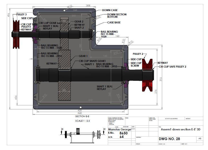
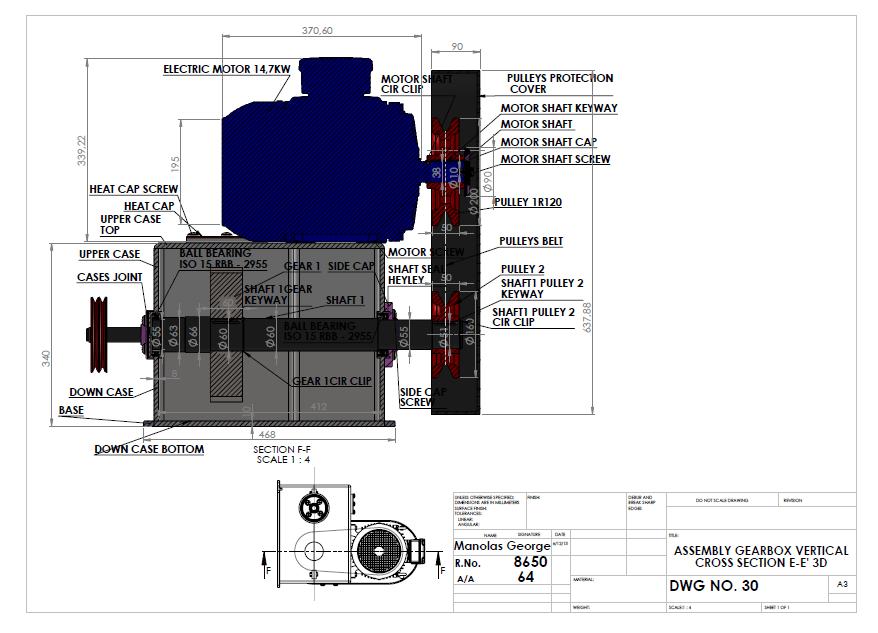
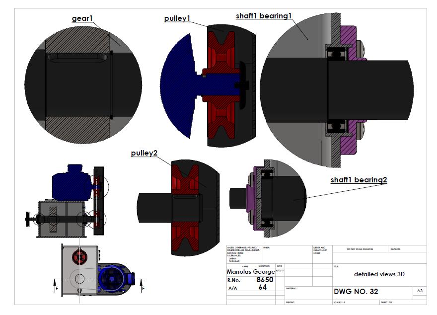
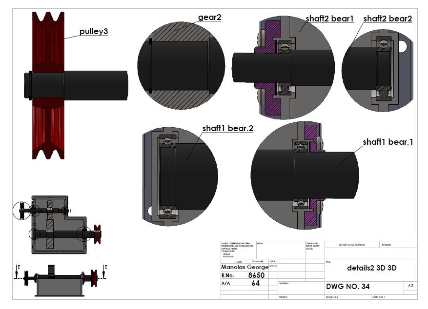
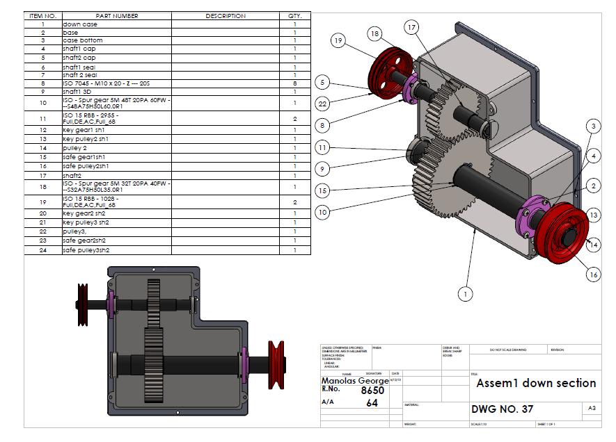
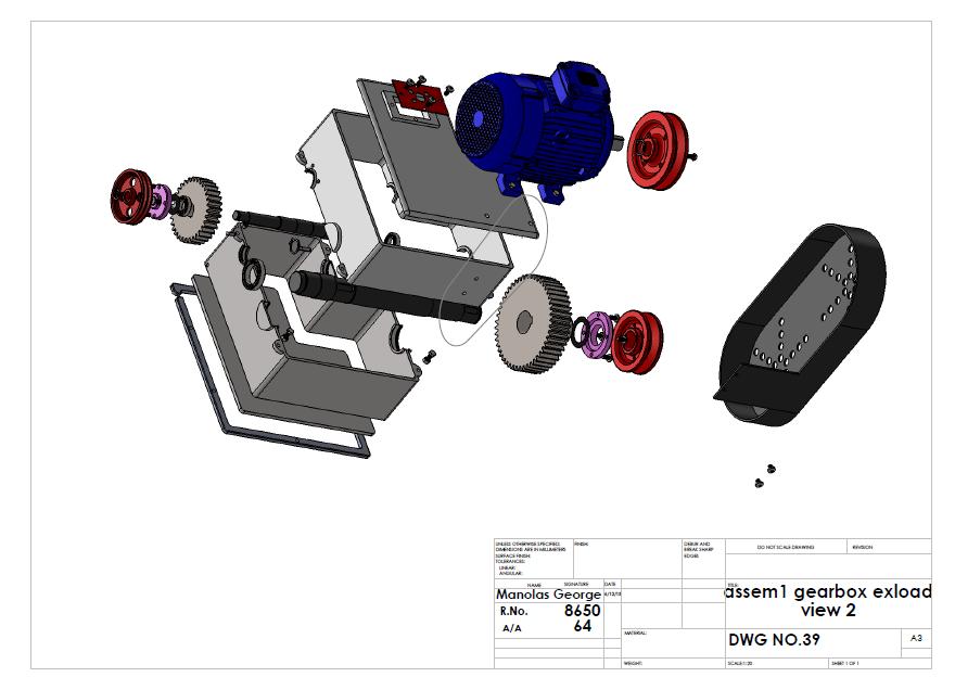
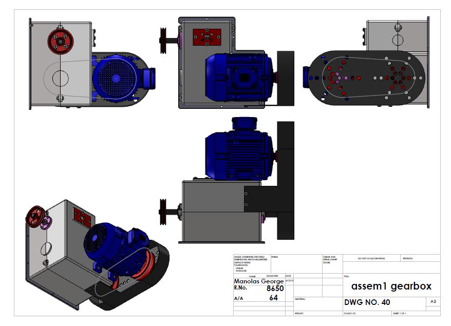
3 Assignment No 1: Shaft Design Figure 1 shows a simple gear box with various machine elements and components. Shaft No. 2 is rotating through gears by shaft No. 1 which is rotating through two pulleys by an electric motor. The transmission shaft No. 1 stands on two bearings and the rotational speed is transfer by the belt. The two shafts are made of hot-rolled alloy steel with yield strength σy= 500 MPa and σuts= 1200 MPa. The belt transmits (a) 14,7KW of power at (b) 1700 rpm. The belt is prestressed with a ration of (c) 2,05 The two gears are spur gears with 20 ο pressure angle. The bearing distance for the shaft 1 is (d) L1= 420 mm and for the shaft 2 is (e) L2= 260 mm. The output pulley has to be design for (f) Nb= 2 number of belts. For both shaft the safety factor is (g) SF= 3,3 - Data for each student: (a/a 64.) Α. CALCULATIONS 1. Calculate the smallest safe shaft diameter for the shaft 1 and 2. Provide a free body diagram and all necessary bending moments and torque diagrams. 2. Calculate the dimensions of the keys and the keyways at shaft 1 and 2 for the two gears and the pulleys. 3. Determine the critical speed of rotating shaft 2. B. DRAWINGS AND ASSEMBLY 1. Make the construction drawings of all different parts (2D) 2. Design the two shafts (shaft 1 and shaft 2 ) with all components and explain in details and explain in details how to make the assembly (assembly manual). 3. Design two different cross sections of the device with all components (2D). 4. Design the gear box with all components in 3D. VERY IMPORTANT NOTES * Estimate all dimensions that are not given. ** Useful documents: Cover for Assignment, Drawing template example *** You must submit one hard copy and one pdf file with all calculations and drawings 3
4 INTRODUCTION The purpose of this assignment is to : Determine the smallest safe diameter for the two shafts using the ASME design code for transmission shafts. Calculate the dimensions of the keys and the keyways at shaft 1 and 2 for the two gears and the pulleys. Calculate the critical speed of rotation for shaft 2. Prepare the construction drawings of the device. Design the full 3D part and two different cress sections. Data : Power transmitted by shafts = 14,7KW Rotational speed of driving pulley = 1700rpm Pre stress belt ratio = 2,05 Gear pressure angle = 20 deg Safety Factor SF or n s = 2,7 Yield strength of shaft material = σ y =500 MPa Ultimate tensile strength of shaft material = σ uts = 1200 MPa Material of keys AISI 1020 cold drawn = σ y = 350 MPa A/A student data = 64 4
5 Schematical illustration of assembly 5
6 1. General calculations for shaft 1 Calculate angular velocity for shaft 1 ω n *R n =ω s *R s => 1700*100=ω s *80 => ω s =2125 rpm Calculate the shaft 1 input torque Torque = power/ angular velocity T q1 =14700w/222,53= 66,06 Nm Calculate the belt tension Belt ratio: 2,05 Pulley 2 radius: 0,08m T 1 =2.05*T 2 T q1 =2,05*T 2 *R-T 2 *R 66,06=2,05T 2 *0,08-0,08*T 2 T 2 =66,06/0,084 T 2 =786,43 N And T 1 =1612,2 N 6
7 Calculate the tangential and radial forces of gear 1 Radius of gear 1= R gear1 =0,120m The tangential force is given by: F t =torque/ R gear1 =66,06N/0,120m => F t =550,5N The radial force is given by: F r =F t *tan20 o = 550,5N*tan20 o => F r =200,37N 7
8 2. Shaft 1 forces and reactions Free body diagram shaft1 Calculating the reactions on z-x plane By taking moments at point A 550,5N*130mm+R 2z *420=2398,63*570 R 2z =3084,9N By summation of forces z-x plane Σf z =0 R 1z +2398,63=550,5+3084,9 R 1z =1236,7N 8
9 Calculating the reactions on y-x plane By taking moments at point A 200,37*130=R 2y *420 R 2y =62,02N By summation of forces y-x plane Σf y =0 200,37-62,02-R 1y =0 R 1y =138,35N 3. Bending moment and torque diagrams for shaft 1 130mm 290mm 150mm Ft=550,5 N R2z=3084,9 N A B C D R1z=1236,7 N T1+T2=2398,63 N Mb=-160,38 Nm Mc=-359,77 Nm Moment diagram in z-x plane The bending moment at B and C in Z-X plane are given by: M b =-R 1z *0,13=1236,7*0,13=-160,38Nm M c =-R 1z *0,42+F t *0,29=-519, ,645=-359,77Nm 9
10 130mm 290mm 150mm Fr=200,37 N A B C D R1y=138,35 N R2y=62,02 N Mb=-18 Nm Moment diagram in y-x plane The bending moment at B and C in Y-X are given by: M b =-R 1y *0,13=-138,35*0,13=-18Nm M c =R 1y *(0,13+0,29)+F r *0,29=-138,35*0,42+200,37*0,29 M c =58, ,107=0,0003Nm 10
11 130mm 290mm 150mm A B C D Tx(Nm) Tq=66,06 X(m) Torque diagram The resultant moment at b is M b = M 2 bz +M 2 by = (-160,38) 2 +(-18) 2 =161,39Nm The moment at point C is: M c = M 2 cz +M 2 cy = (-359,77) 2 +(0,0003) 2 =359,77Nm As seen from the bending moment diargams the maximum moment occurs at point C at the bearing and has a value of 359,77Nm The torque is constant (66,06Nm) between points B and D. The critical point of the shaft is at point C. M x =359,77Nm Torque=66,06Nm 11
12 4. Determine the smallest safe diameter Calculation of the endurance limit σ e for shaft 1 Data: n s =3,3, σ y =500Μpa, Mc=359,77Nm, Tc=66,06Nm, σ uts =1200Mpa σ e =Ka*Kb*Kc*Kd*Ke*Kf*Kg* σ e σ e =0,504* σ uts =0,504*1200=604,8Mpa Ka=surface factor (hot rolled steel) Ka=a* σ b uts =57,7*1200-0,718 =0,35 Kb=size factor Kb=(d/7,62) -0,1133 =(47/7,62) -0,1133 =0,8134 Kc=reliability, 90% Kc=0,897 Kd=temperature factor Kd=1 Ke=duty cycle Ke=1 Kf=fatigue stress Kf=0,63 Kg=various Kg=1 σ e =0,35*0,856*0,897*1*1*0,63*1*0,604,8 σ e =97,3Mpa The smallest safe diameter for shaft 1 is given by ( ) =0,050m The smallest safe diameter for shaft1 is d=50mm 12
13 5. General calculations for shaft 2 Calculate angular velocity for shaft 2 Ω g1 *R g1 =ω g2 *R g2 => 1700*0,12=ω s *0,08 => ω g2 =3187,5 rpm Calculate the shaft 2 input torque Torque = power/ angular velocity T q1 =14700w/333,79= 44,04 Nm Calculate the tangential and radial forces of gear 2 The tangential and radial forces are equal and opposite to the ones on gear 2 F t =550,5N F r =200,37N 13
14 6. Shaft 2 forces and reactions Free body diagram shaft 2 Calculating the reactions on z-x plane By taking moments at point B -550,5N*130mm+R 2z *260mm=0 R 2z =275,25N By summation of forces z-x plane Σf z =0 R 1z -F t +R 2z =0 R 1z =550,5-275,25 R 1z =275,25N 14
15 Calculating the reactions on y-x plane By taking moments at point B -200,37*130=R 2y *260 R 2y =100,18N By summation of forces y-x plane Σf y =0-200,37+100,18+R 1y =0 R 1y =100,19N 7. Bending moment and torque diagrams for shaft 2 The bending moment at B and C in Z-X plane are given by: M b =-550,5*0,13+275,25*0,26=0Nm M c =R 1z *0,13=275,25*0,13=35,8Nm 130mm 130mm 130mm R1z=275,25 N A B C D R2z=275,25N Mz(Nm) Ft=550,5 N Mc=35,8 Nm X(m) Moment diagram in Z-X plane 15
16 The bending moment at C in Y-X are given by: M b =100,18*0,26-200,37*0,13=0Nm M c =R 1y *0,13=13,025Nm 130mm 130mm 130mm R1y100,19 N A B C D R2y=100,18 N Mz(Nm) Ft200,37 N Mc=13,025 Nm X(m) 16
17 Torque diagram 130mm 130mm 130mm R2z=275,25N R1z=275,25 N A B C D Tx(Nm) Tq44,04 Nm X(m) The resultant moment at b is M b = M 2 bz +M 2 by = (0) 2 +(0) 2 =0Nm The moment at point C is: M c = M 2 cz +M 2 cy = (35,8) 2 +(13,025) 2 =38,1Nm As seen from the bending moment diargams the maximum moment occurs at point C at the gear and has a value of 38,1Nm The torque is constant (44,04Nm) between points A and C. The critical point of the shaft is at point C. M x =38,1Nm Torque=44,04Nm 17
18 8. Determine the smallest safe diameter Calculation of the endurance limit σ e for shaft 2 Data: n s =3,3, σ y =500Μpa, Mc=38,1Nm, Tc=44,04Nm, σ uts =1200Mpa σ e =Ka*Kb*Kc*Kd*Ke*Kf*Kg* σ e σ e =0,504* σ uts =0,504*1200=604,8Mpa Ka=surface factor (hot rolled steel) Ka=a* σ b uts =57,7*1200-0,718 =0,35 Kb=size factor Kb=(d/7,62) -0,1133 =(25/7,62) -0,1133 =0,87405 Kc=reliability, 90% Kc=0,897 Kd=temperature factor Kd=1 Ke=duty cycle Ke=1 Kf=fatigue stress Kf=0,63 Kg=various Kg=1 σ e =0,35*0,7405*0,897*1*1*0,63*1*0,604,8 σ e =104,56Mpa The smallest safe diameter for shaft 1 is given by ( ) =0,023m The smallest safe diameter for shaft2 is d=23mm 18

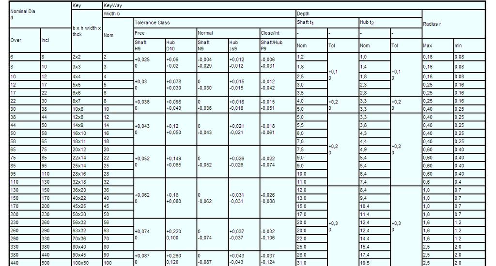
19 9. Calculations of the keys and keyways Keys are used to secure the pulleys and gears on the shafts. They are used to transmit the torque from the shafts to the rotating elements. The size of the keys depends on the shaft diameter and is taken form the British Standard Metric Keyways for Square and Rectangular Parallel Keys table. They can fail from shear and from bearing. Shear stress calculation T design =P/A s P=T/0,5d=2T/d A s =b*l, T design =2T/dbl To avoid failure due to shear T design 0,4Sy/n s Bearing stress calculation Failure due to compressive or bearing stress The compression or bearing area of the keys is A c =l*h/2, σ design =P/A c =2T/0,5*dlh=4T/dlh To avoid failure due to compressive or bearing stress: σ design 0,9*S y /n s 19
20 Calculation of the key and the keyway for pulley 2 on shaft 1 Shaft dia= d=51mm Torque= T=66,06Nm Key yield strength σ y =350Mpa Key size (mm)= 30x16x10 Keyway size (mm)=30x16x6(depth) (4,3 hub) A. Failure due to shear T design =2*66.06/0,051*0,030*0,016=5,4Mpa n s =0,4*S y /T design =0,4*350/5,4=25,9 B. Failure due to bearing σ design =P/A c =4*66,06/0,051*0,03*0,01=17,3Mpa n S =0,9*S y /σ design = 0,9*350/17,3=18,2 Calculation of the key and the keyway for gear 1 on shaft 1 Shaft dia= d=60mm Torque= T=66,06Nm Key yield strength σ y =350Mpa Key size (mm)= 38x18x11 Keyway size (mm)=38x18x7(depth) (4,4 hub) A. Failure due to shear T design =2*66.06/0,06*0,038*0,018=3,22Mpa n s =0,4*S y /T design =0,4*350/3,22=43,5 20
21 B. Failure due to bearing σ design =P/A c =4*66,06/0,06*0,038*0,011=10,5Mpa n S =0,9*S y /σ design = 0,9*350/10,5=30 Calculation of the key and the keyway for pulley3 on shaft 2 Shaft dia= d=24mm Torque= T=44.04Nm Key yield strength σ y =350Mpa Key size (mm)= 18x8x7 Keyway size (mm)=18x8x4(depth) (3,3 hub) A. Failure due to shear T design =2*44.04/0,024*0,018*0,006=34Mpa n s =0,4*S y /T design =0,4*350/34=4,12 B. Failure due to bearing σ design =P/A c =4*44,04/0,024*0,018*0,007=58,25Mpa n S =0,9*S y /σ design = 0,9*350/10,5=5,41 21
22 Calculation of the key and the keyway for gear 2 on shaft 2 Shaft dia= d=34mm Torque= T=44.04Nm Key yield strength σ y =350Mpa Key size (mm)= 26x10x8 Keyway size (mm)=26x10x5(depth) (3,3 hub) A. Failure due to shear T design =2*44,04/0,034*0,026*0,01=9,9Mpa n s =0,4*S y /T design =0,4*350/9,9=14,14 B. Failure due to bearing σ design =P/A c =4*44,04/0,034*0,026*0,008=25Mpa n S =0,9*S y /σ design = 0,9*350/25=12,6 22
23 10. Calculations of the critical speed of rotation for shaft 2 the calculations for the critical speed are based on the diameter of the shaft between points B and C. the maximum deflection is at point C. shaft diameter d = 35mm Yang s modulus of elasticity E = N/mm 2 Find the resultant force at point C F= F t 2 +F r 2 F= 550, ,37 2 = 585,83 N The second moment of area of the shaft for 35mm diameter is: = π*35 4 /64 = mm 4 Calculation of the maximum deflection at point C The shaft at boints B and D behaves like a simply supported beam. The maximum deflection is given by: Calculation of the critical speed of rotation The critical speed is given by: 23
24 The critical speed in RPM is given by: The critical speed of rotation for shaft 2 is 7965 RPM So the critical rotational speed of shaft 2 is much larger than the actual. 24
25 11. Attachments 25
26 12. References 1) Shingley s mechanical engineering design eighth edition 2008 by Richard G. 2) Fundamentals of machine elements second edition 2006 by Hamrock, Shmid and Jacobson 3) Mechanical design second edition 2004 by Peter Childs 4) British standard metric keyways for square and rectangular parallel keys 5) Solid works gears and pulleys libraries 6) Roymech.co.uk tables for keys and keyways. 13. Drawings 26
27 27
28 28
29 29
30 30
31 31
32 32
33 33
34 34
35 35
36 36
37 37
38 38
39 39
40 40
41 41
42 42
43 43
44 44
45 45
46 46
47 47
48 48
49 49
50 50
51 51
52 52
53 53
54 54
55 55
56 56
57 57
58 58
59 59
60 60
61 61
62 62
63 63
64 64
65 65
66 66
67 67
ENT345 Mechanical Components Design
 1) LOAD AND STRESS ANALYSIS i. Principle stress ii. The maximum shear stress iii. The endurance strength of shaft. 1) Problem 3-71 A countershaft carrying two-v belt pulleys is shown in the figure. Pulley
MEMS Project 2 Assignment. Design of a Shaft to Transmit Torque Between Two Pulleys
 MEMS 029 Project 2 Assignment Design of a Shaft to Transmit Torque Between Two Pulleys Date: February 5, 206 Instructor: Dr. Stephen Ludwick Product Definition Shafts are incredibly important in order
Stress Analysis Lecture 3 ME 276 Spring Dr./ Ahmed Mohamed Nagib Elmekawy
 Stress Analysis Lecture 3 ME 276 Spring 2017-2018 Dr./ Ahmed Mohamed Nagib Elmekawy Axial Stress 2 Beam under the action of two tensile forces 3 Beam under the action of two tensile forces 4 Shear Stress
SOLUTION (17.3) Known: A simply supported steel shaft is connected to an electric motor with a flexible coupling.
 Known: A simply supported steel shaft is connected to an electric motor with a flexible coupling.") SOLUTION (17.3) Known: A simply supported steel shaft is connected to an electric motor with a flexible coupling. Find: Determine the value of the critical speed of rotation for the shaft. Schematic and
SOLUTION (17.3) Known: A simply supported steel shaft is connected to an electric motor with a flexible coupling. Find: Determine the value of the critical speed of rotation for the shaft. Schematic and
MECHANICS OF MATERIALS
 2009 The McGraw-Hill Companies, Inc. All rights reserved. Fifth SI Edition CHAPTER 3 MECHANICS OF MATERIALS Ferdinand P. Beer E. Russell Johnston, Jr. John T. DeWolf David F. Mazurek Torsion Lecture Notes:
Mechanical Design. Design of Shaft
 Mechanical Design Design of Shaft Outline Practical information Shaft design Definition of shaft? It is a rotating member, in general, has a circular cross-section and is used to transmit power. The shaft
MAAE 2202 A. Come to the PASS workshop with your mock exam complete. During the workshop you can work with other students to review your work.
 It is most beneficial to you to write this mock final exam UNDER EXAM CONDITIONS. This means: Complete the exam in 3 hours. Work on your own. Keep your textbook closed. Attempt every question. After the
Static Failure (pg 206)
") Static Failure (pg 06) All material followed Hookeʹs law which states that strain is proportional to stress applied, until it exceed the proportional limits. It will reach and exceed the elastic limit
Static Failure (pg 06) All material followed Hookeʹs law which states that strain is proportional to stress applied, until it exceed the proportional limits. It will reach and exceed the elastic limit
Drive Shaft Failure of Z-Drive Propulsion System. Suzanne Higgins
 Drive Shaft Failure of Z-Drive Propulsion System Suzanne Higgins Background Bunkering vessel MV Southern Valour Commissioned in 2008 in Singapore Operating in Cape Town harbour since August 2008 Z-Drive
Bending Stress. Sign convention. Centroid of an area
 Bending Stress Sign convention The positive shear force and bending moments are as shown in the figure. Centroid of an area Figure 40: Sign convention followed. If the area can be divided into n parts
Shafts. Fig.(4.1) Dr. Salah Gasim Ahmed YIC 1
 Dr. Salah Gasim Ahmed YIC 1") Shafts. Power transmission shafting Continuous mechanical power is usually transmitted along and etween rotating shafts. The transfer etween shafts is accomplished y gears, elts, chains or other similar
Shafts. Power transmission shafting Continuous mechanical power is usually transmitted along and etween rotating shafts. The transfer etween shafts is accomplished y gears, elts, chains or other similar
CHAPTER 2 Failure/Fracture Criterion
 (11) CHAPTER 2 Failure/Fracture Criterion (12) Failure (Yield) Criteria for Ductile Materials under Plane Stress Designer engineer: 1- Analysis of loading (for simple geometry using what you learn here
Note: Read section (12-1) objective of this chapter (Page 532)
 objective of this chapter (Page 532)") References: Machine Elements in Mechanical Design by Robert L. Mott, P.E. (Chapter 12 Note: Read section (12-1 objective of this chapter (Page 532 Page 1 of 29 Shaft Design Procedure (Sec. 12-2, Page 532
References: Machine Elements in Mechanical Design by Robert L. Mott, P.E. (Chapter 12 Note: Read section (12-1 objective of this chapter (Page 532 Page 1 of 29 Shaft Design Procedure (Sec. 12-2, Page 532
4. SHAFTS. A shaft is an element used to transmit power and torque, and it can support
 4. SHAFTS A shaft is an element used to transmit power and torque, and it can support reverse bending (fatigue). Most shafts have circular cross sections, either solid or tubular. The difference between
2. Polar moment of inertia As stated above, the polar second moment of area, J is defined as. Sample copy
 GATE PATHSHALA - 91. Polar moment of inertia As stated above, the polar second moment of area, is defined as z π r dr 0 R r π R π D For a solid shaft π (6) QP 0 π d Solid shaft π d Hollow shaft, " ( do
Matlab Sheet 2. Arrays
 Matlab Sheet 2 Arrays 1. a. Create the vector x having 50 logarithmically spaced values starting at 10 and ending at 1000. b. Create the vector x having 20 logarithmically spaced values starting at 10
OUTCOME 1 - TUTORIAL 3 BENDING MOMENTS. You should judge your progress by completing the self assessment exercises. CONTENTS
 Unit 2: Unit code: QCF Level: 4 Credit value: 15 Engineering Science L/601/1404 OUTCOME 1 - TUTORIAL 3 BENDING MOMENTS 1. Be able to determine the behavioural characteristics of elements of static engineering
Shafts Introduction. Shafts 509
 Shafts 509 C H A P T E R 14 Shafts 1. Introduction.. Material Used for Shafts.. Manufacturing of Shafts. 4. Types of Shafts. 5. Standard Sizes of Transmission Shafts. 6. Stresses in Shafts. 7. Maximum
Automated Spur Gear Designing Using MATLAB
 Kalpa Publications in Engineering Volume 1, 2017, Pages 493 498 ICRISET2017. International Conference on Research and Innovations in Science, Engineering &Technology. Selected Papers in Engineering Automated
MECHANICS OF MATERIALS Design of a Transmission Shaft
 Design of a Transmission Shaft If power is transferred to and from the shaft by gears or sprocket wheels, the shaft is subjected to transverse loading as well as shear loading. Normal stresses due to transverse
Revision Term 2. Prof Ahmed Kovacevic
 ME 1110 Engineering Practice 1 Engineering Drawing and Design - Lecture 20 Revision Term 2 Prof Ahmed Kovacevic School of Engineering and Mathematical Sciences Room CG25, Phone: 8780, E-Mail: a.kovacevic@city.ac.uk
Sample Question Paper
 Scheme I Sample Question Paper Program Name : Mechanical Engineering Program Group Program Code : AE/ME/PG/PT/FG Semester : Third Course Title : Strength of Materials Marks : 70 Time: 3 Hrs. Instructions:
Helical Gears n A Textbook of Machine Design
 1066 n A Textbook of Machine Design C H A P T E R 9 Helical Gears 1. Introduction.. Terms used in Helical Gears. 3. Face Width of Helical Gears. 4. Formative or Equivalent Number of Teeth for Helical Gears.
3.5 STRESS AND STRAIN IN PURE SHEAR. The next element is in a state of pure shear.
 3.5 STRESS AND STRAIN IN PURE SHEAR The next element is in a state of pure shear. Fig. 3-20 Stresses acting on a stress element cut from a bar in torsion (pure shear) Stresses on inclined planes Fig. 3-21
Torsion of shafts with circular symmetry
 orsion of shafts with circular symmetry Introduction Consider a uniform bar which is subject to a torque, eg through the action of two forces F separated by distance d, hence Fd orsion is the resultant
CIVL222 STRENGTH OF MATERIALS. Chapter 6. Torsion
 CIVL222 STRENGTH OF MATERIALS Chapter 6 Torsion Definition Torque is a moment that tends to twist a member about its longitudinal axis. Slender members subjected to a twisting load are said to be in torsion.
Chapter 8 Structural Design and Analysis. Strength and stiffness 5 types of load: Tension Compression Shear Bending Torsion
 Chapter 8 Structural Design and Analysis 1 Strength and stiffness 5 types of load: Tension Compression Shear Bending Torsion Normal Stress Stress is a state when a material is loaded. For normal forces
Tuesday, February 11, Chapter 3. Load and Stress Analysis. Dr. Mohammad Suliman Abuhaiba, PE
 1 Chapter 3 Load and Stress Analysis 2 Chapter Outline Equilibrium & Free-Body Diagrams Shear Force and Bending Moments in Beams Singularity Functions Stress Cartesian Stress Components Mohr s Circle for
MECE 3321: MECHANICS OF SOLIDS CHAPTER 5
 MECE 3321: MECHANICS OF SOLIDS CHAPTER 5 SAMANTHA RAMIREZ TORSION Torque A moment that tends to twist a member about its longitudinal axis 1 TORSIONAL DEFORMATION OF A CIRCULAR SHAFT Assumption If the
2. Determine the deflection at C of the beam given in fig below. Use principal of virtual work. W L/2 B A L C
 CE-1259, Strength of Materials UNIT I STRESS, STRAIN DEFORMATION OF SOLIDS Part -A 1. Define strain energy density. 2. State Maxwell s reciprocal theorem. 3. Define proof resilience. 4. State Castigliano
Design against fluctuating load
 Design against fluctuating load In many applications, the force acting on the spring is not constants but varies in magnitude with time. The valve springs of automotive engine subjected to millions of
MECHANICS OF SOLIDS TORSION - TUTORIAL 1. You should judge your progress by completing the self assessment exercises.
 MECHANICS OF SOIS TORSION - TUTORIA 1 You should judge your progress by completing the self assessment exercises. On completion of this tutorial you should be able to do the following. erive the torsion
PDDC 1 st Semester Civil Engineering Department Assignments of Mechanics of Solids [ ] Introduction, Fundamentals of Statics
![PDDC 1 st Semester Civil Engineering Department Assignments of Mechanics of Solids [ ] Introduction, Fundamentals of Statics](/thumbs/92/109382806.jpg "PDDC 1 st Semester Civil Engineering Department Assignments of Mechanics of Solids [ ] Introduction, Fundamentals of Statics") Page1 PDDC 1 st Semester Civil Engineering Department Assignments of Mechanics of Solids [2910601] Introduction, Fundamentals of Statics 1. Differentiate between Scalar and Vector quantity. Write S.I.
Page1 PDDC 1 st Semester Civil Engineering Department Assignments of Mechanics of Solids [2910601] Introduction, Fundamentals of Statics 1. Differentiate between Scalar and Vector quantity. Write S.I.
NAME: Given Formulae: Law of Cosines: Law of Sines:
 NME: Given Formulae: Law of Cosines: EXM 3 PST PROBLEMS (LESSONS 21 TO 28) 100 points Thursday, November 16, 2017, 7pm to 9:30, Room 200 You are allowed to use a calculator and drawing equipment, only.
Improvement in Design & Development of Multi-Spindle Drilling Head Machine
 Improvement in Design & Development of Multi-Spindle Drilling Head Machine Prof. Vivek I. Akolkar 1, Prof. Vikas I. Somankar 2, Prof. M. M. Patil 3 1,2 Assistant Professor, Department of Mechanical Engineering,
Chapter 5: Torsion. 1. Torsional Deformation of a Circular Shaft 2. The Torsion Formula 3. Power Transmission 4. Angle of Twist CHAPTER OBJECTIVES
 CHAPTER OBJECTIVES Chapter 5: Torsion Discuss effects of applying torsional loading to a long straight member (shaft or tube) Determine stress distribution within the member under torsional load Determine
EMA 3702 Mechanics & Materials Science (Mechanics of Materials) Chapter 3 Torsion
 Chapter 3 Torsion") EMA 3702 Mechanics & Materials Science (Mechanics of Materials) Chapter 3 Torsion Introduction Stress and strain in components subjected to torque T Circular Cross-section shape Material Shaft design Non-circular
EMA 3702 Mechanics & Materials Science (Mechanics of Materials) Chapter 3 Torsion Introduction Stress and strain in components subjected to torque T Circular Cross-section shape Material Shaft design Non-circular
Engineering Science OUTCOME 1 - TUTORIAL 4 COLUMNS
 Unit 2: Unit code: QCF Level: Credit value: 15 Engineering Science L/601/10 OUTCOME 1 - TUTORIAL COLUMNS 1. Be able to determine the behavioural characteristics of elements of static engineering systems
ME C85/CE C30 Midterm 2. Introduction to Solid Mechanics ME C85/CE C30. Midterm Exam 2. Fall, 2013
 ME C85/CE C30 Midterm 2 Introduction to Solid Mechanics ME C85/CE C30 Midterm Exam 2 1. Do not open the exam until you are told to begin. 2. Put your name and SID on every page of your answer book. 3.
Automobile manual transmission
 Design of Shaft A shaft is a rotating member usually of circular crosssection (soli or hollow), which is use to transmit power an rotational motion. Axles are non rotating member. Elements such as gears,
ASSOCIATE DEGREE IN ENGINEERING EXAMINATIONS. SEMESTER 2 May 2013
 ASSOCIATE DEGREE IN ENGINEERING EXAMINATIONS SEMESTER 2 May 2013 COURSE NAME: CODE: Mechanical Engineering Science [8 CHARACTER COURSE CODE] GROUP: AD-ENG 1 DATE: TIME: DURATION: "[EXAM DATE]" "[TIME OF
QUESTION BANK SEMESTER: III SUBJECT NAME: MECHANICS OF SOLIDS
 QUESTION BANK SEMESTER: III SUBJECT NAME: MECHANICS OF SOLIDS UNIT 1- STRESS AND STRAIN PART A (2 Marks) 1. Define longitudinal strain and lateral strain. 2. State Hooke s law. 3. Define modular ratio,
[7] Torsion. [7.1] Torsion. [7.2] Statically Indeterminate Torsion. [7] Torsion Page 1 of 21
![[7] Torsion. [7.1] Torsion. [7.2] Statically Indeterminate Torsion. [7] Torsion Page 1 of 21](/thumbs/88/115835122.jpg "[7] Torsion. [7.1] Torsion. [7.2] Statically Indeterminate Torsion. [7] Torsion Page 1 of 21") [7] Torsion Page 1 of 21 [7] Torsion [7.1] Torsion [7.2] Statically Indeterminate Torsion [7] Torsion Page 2 of 21 [7.1] Torsion SHEAR STRAIN DUE TO TORSION 1) A shaft with a circular cross section is
[7] Torsion Page 1 of 21 [7] Torsion [7.1] Torsion [7.2] Statically Indeterminate Torsion [7] Torsion Page 2 of 21 [7.1] Torsion SHEAR STRAIN DUE TO TORSION 1) A shaft with a circular cross section is
High Tech High Top Hat Technicians. An Introduction to Solid Mechanics. Is that supposed to bend there?
 High Tech High Top Hat Technicians An Introduction to Solid Mechanics Or Is that supposed to bend there? Why don't we fall through the floor? The power of any Spring is in the same proportion with the
2014 MECHANICS OF MATERIALS
 R10 SET - 1 II. Tech I Semester Regular Examinations, March 2014 MEHNIS OF MTERILS (ivil Engineering) Time: 3 hours Max. Marks: 75 nswer any FIVE Questions ll Questions carry Equal Marks ~~~~~~~~~~~~~~~~~~~~~~~~~
Module 2 Stresses in machine elements. Version 2 ME, IIT Kharagpur
 Module Stresses in machine elements Lesson Compound stresses in machine parts Instructional Objectives t the end of this lesson, the student should be able to understand Elements of force system at a beam
Chapter 3. Load and Stress Analysis. Lecture Slides
 Lecture Slides Chapter 3 Load and Stress Analysis 2015 by McGraw Hill Education. This is proprietary material solely for authorized instructor use. Not authorized for sale or distribution in any manner.
Determine the resultant internal loadings acting on the cross section at C of the beam shown in Fig. 1 4a.
 E X M P L E 1.1 Determine the resultant internal loadings acting on the cross section at of the beam shown in Fig. 1 a. 70 N/m m 6 m Fig. 1 Support Reactions. This problem can be solved in the most direct
SECOND ENGINEER REG. III/2 APPLIED MECHANICS
 SECOND ENGINEER REG. III/2 APPLIED MECHANICS LIST OF TOPICS Static s Friction Kinematics Dynamics Machines Strength of Materials Hydrostatics Hydrodynamics A STATICS 1 Solves problems involving forces
QUESTION BANK DEPARTMENT: CIVIL SEMESTER: III SUBJECT CODE: CE2201 SUBJECT NAME: MECHANICS OF SOLIDS UNIT 1- STRESS AND STRAIN PART A
 DEPARTMENT: CIVIL SUBJECT CODE: CE2201 QUESTION BANK SEMESTER: III SUBJECT NAME: MECHANICS OF SOLIDS UNIT 1- STRESS AND STRAIN PART A (2 Marks) 1. Define longitudinal strain and lateral strain. 2. State
MARKS DISTRIBUTION AS PER CHAPTER (QUESTION ASKED IN GTU EXAM) Name Of Chapter. Applications of. Friction. Centroid & Moment.
 Name Of Chapter. Applications of. Friction. Centroid & Moment.") Introduction Fundamentals of statics Applications of fundamentals of statics Friction Centroid & Moment of inertia Simple Stresses & Strain Stresses in Beam Torsion Principle Stresses DEPARTMENT OF CIVIL
Introduction Fundamentals of statics Applications of fundamentals of statics Friction Centroid & Moment of inertia Simple Stresses & Strain Stresses in Beam Torsion Principle Stresses DEPARTMENT OF CIVIL
The example of shafts; a) Rotating Machinery; Propeller shaft, Drive shaft b) Structural Systems; Landing gear strut, Flap drive mechanism
 Rotating Machinery; Propeller shaft, Drive shaft b) Structural Systems; Landing gear strut, Flap drive mechanism") TORSION OBJECTIVES: This chapter starts with torsion theory in the circular cross section followed by the behaviour of torsion member. The calculation of the stress stress and the angle of twist will be
TORSION OBJECTIVES: This chapter starts with torsion theory in the circular cross section followed by the behaviour of torsion member. The calculation of the stress stress and the angle of twist will be
WORCESTER POLYTECHNIC INSTITUTE
 WORCESTER POLYTECHNIC INSTITUTE MECHANICAL ENGINEERING DEPARTMENT STRESS ANALYSIS ES-2502, C 2012 Lecture 17: 10 February 2012 General information Instructor: Cosme Furlong HL-151 (508) 831-5126 cfurlong@wpi.edu
UNIT-I STRESS, STRAIN. 1. A Member A B C D is subjected to loading as shown in fig determine the total elongation. Take E= 2 x10 5 N/mm 2
 UNIT-I STRESS, STRAIN 1. A Member A B C D is subjected to loading as shown in fig determine the total elongation. Take E= 2 x10 5 N/mm 2 Young s modulus E= 2 x10 5 N/mm 2 Area1=900mm 2 Area2=400mm 2 Area3=625mm
Please review the following statement: I certify that I have not given unauthorized aid nor have I received aid in the completion of this exam.
 Group Number: Please review the following statement: I certify that I have not given unauthorized aid nor have I received aid in the completion of this exam. Signature: INSTRUCTIONS Begin each problem
Mechanical Engineering Ph.D. Preliminary Qualifying Examination Solid Mechanics February 25, 2002
 student personal identification (ID) number on each sheet. Do not write your name on any sheet. #1. A homogeneous, isotropic, linear elastic bar has rectangular cross sectional area A, modulus of elasticity
Chapter 5 Torsion STRUCTURAL MECHANICS: CE203. Notes are based on Mechanics of Materials: by R. C. Hibbeler, 7th Edition, Pearson
 STRUCTURAL MECHANICS: CE203 Chapter 5 Torsion Notes are based on Mechanics of Materials: by R. C. Hibbeler, 7th Edition, Pearson Dr B. Achour & Dr Eng. K. El-kashif Civil Engineering Department, University
ME Final Exam. PROBLEM NO. 4 Part A (2 points max.) M (x) y. z (neutral axis) beam cross-sec+on. 20 kip ft. 0.2 ft. 10 ft. 0.1 ft.
 M (x) y. z (neutral axis) beam cross-sec+on. 20 kip ft. 0.2 ft. 10 ft. 0.1 ft.") ME 323 - Final Exam Name December 15, 2015 Instructor (circle) PROEM NO. 4 Part A (2 points max.) Krousgrill 11:30AM-12:20PM Ghosh 2:30-3:20PM Gonzalez 12:30-1:20PM Zhao 4:30-5:20PM M (x) y 20 kip ft 0.2
ME 323 - Final Exam Name December 15, 2015 Instructor (circle) PROEM NO. 4 Part A (2 points max.) Krousgrill 11:30AM-12:20PM Ghosh 2:30-3:20PM Gonzalez 12:30-1:20PM Zhao 4:30-5:20PM M (x) y 20 kip ft 0.2
The problem of transmitting a torque or rotary motion from one plane to another is frequently encountered in machine design.
 CHAPER ORSION ORSION orsion refers to the twisting of a structural member when it is loaded by moments/torques that produce rotation about the longitudinal axis of the member he problem of transmitting
DESIGN OF SHAFT UNDER FATIGUE LOADING
 DESIGN OF SHAFT UNDER FATIGUE LOADING Aditya Anand, Ashish Aggarwal, Jatin Kumar Mechanical Engineering, Dronacharya College of Engineering, Khentawas, Gurgaon, INDIA Abstract - In this paper, shaft employed
PERIYAR CENTENARY POLYTECHNIC COLLEGE PERIYAR NAGAR - VALLAM THANJAVUR. DEPARTMENT OF MECHANICAL ENGINEERING QUESTION BANK
 PERIYAR CENTENARY POLYTECHNIC COLLEGE PERIYAR NAGAR - VALLAM - 613 403 - THANJAVUR. DEPARTMENT OF MECHANICAL ENGINEERING QUESTION BANK Sub : Strength of Materials Year / Sem: II / III Sub Code : MEB 310
Unit Workbook 1 Level 4 ENG U8 Mechanical Principles 2018 UniCourse Ltd. All Rights Reserved. Sample
 Pearson BTEC Levels 4 Higher Nationals in Engineering (RQF) Unit 8: Mechanical Principles Unit Workbook 1 in a series of 4 for this unit Learning Outcome 1 Static Mechanical Systems Page 1 of 23 1.1 Shafts
PES Institute of Technology
 PES Institute of Technology Bangalore south campus, Bangalore-5460100 Department of Mechanical Engineering Faculty name : Madhu M Date: 29/06/2012 SEM : 3 rd A SEC Subject : MECHANICS OF MATERIALS Subject
Name :. Roll No. :... Invigilator s Signature :.. CS/B.TECH (CE-NEW)/SEM-3/CE-301/ SOLID MECHANICS
/SEM-3/CE-301/ SOLID MECHANICS") Name :. Roll No. :..... Invigilator s Signature :.. 2011 SOLID MECHANICS Time Allotted : 3 Hours Full Marks : 70 The figures in the margin indicate full marks. Candidates are required to give their answers
Name :. Roll No. :..... Invigilator s Signature :.. 2011 SOLID MECHANICS Time Allotted : 3 Hours Full Marks : 70 The figures in the margin indicate full marks. Candidates are required to give their answers
Design and Analysis of a gearbox for an all terrain vehicle
 Design and Analysis of a gearbox for an all terrain vehicle Ms.Asmita Patil 1, Mr.Bhoraj Kale 2, Atharva Bhagade 3, Chinmay Pimpalkhute 4, Ashirwad Borkar 5 1 Professor, Department of Mechanical Engineering,
Design Approaches for Employing Enhanced Transmission Efficiency in Over Head Cranes Ankit V Prajapati 1 Prof. Amit R Patel 2 Prof. Dhaval P.
 IJSRD - Internation Journ for Scientific Research & Development Vol. 3, Issue 03, 2015 ISSN (online): 2321-0613 Design Approaches for Employing Enhanced Transmission Efficiency in Over Head Cranes Ankit
INTERNATIONAL JOURNAL OF PURE AND APPLIED RESEARCH IN ENGINEERING AND TECHNOLOGY
 INTERNATIONAL JOURNAL OF PURE AND APPLIED RESEARCH IN ENGINEERING AND TECHNOLOGY A PATH FOR HORIZING YOUR INNOVATIVE WORK HERRINGBONE GEAR ANALYSIS AND CALCULATION OF FORCES ACTING ON IT IN HOT ROLLING
(48) CHAPTER 3: TORSION
 CHAPTER 3: TORSION") (48) CHAPTER 3: TORSION Introduction: In this chapter structural members and machine parts that are in torsion will be considered. More specifically, you will analyze the stresses and strains in members
(48) CHAPTER 3: TORSION Introduction: In this chapter structural members and machine parts that are in torsion will be considered. More specifically, you will analyze the stresses and strains in members
Donald P. Shiley School of Engineering ME 328 Machine Design, Spring 2019 Assignment 1 Review Questions
 Donald P. Shiley School of Engineering ME 328 Machine Design, Spring 2019 Assignment 1 Review Questions Name: This is assignment is in workbook format, meaning you may fill in the blanks (you do not need
R13. II B. Tech I Semester Regular Examinations, Jan MECHANICS OF SOLIDS (Com. to ME, AME, AE, MTE) PART-A
 PART-A") SET - 1 II B. Tech I Semester Regular Examinations, Jan - 2015 MECHANICS OF SOLIDS (Com. to ME, AME, AE, MTE) Time: 3 hours Max. Marks: 70 Note: 1. Question Paper consists of two parts (Part-A and Part-B)
SET - 1 II B. Tech I Semester Regular Examinations, Jan - 2015 MECHANICS OF SOLIDS (Com. to ME, AME, AE, MTE) Time: 3 hours Max. Marks: 70 Note: 1. Question Paper consists of two parts (Part-A and Part-B)
Failure from static loading
 Failure from static loading Topics Quiz /1/07 Failures from static loading Reading Chapter 5 Homework HW 3 due /1 HW 4 due /8 What is Failure? Failure any change in a machine part which makes it unable
IDE 110 Mechanics of Materials Spring 2006 Final Examination FOR GRADING ONLY
 Spring 2006 Final Examination STUDENT S NAME (please print) STUDENT S SIGNATURE STUDENT NUMBER IDE 110 CLASS SECTION INSTRUCTOR S NAME Do not turn this page until instructed to start. Write your name on
Members Subjected to Torsional Loads
 Members Subjected to Torsional Loads Torsion of circular shafts Definition of Torsion: Consider a shaft rigidly clamped at one end and twisted at the other end by a torque T = F.d applied in a plane perpendicular
Name (Print) ME Mechanics of Materials Exam # 2 Date: March 29, 2017 Time: 8:00 10:00 PM - Location: WTHR 200
 ME Mechanics of Materials Exam # 2 Date: March 29, 2017 Time: 8:00 10:00 PM - Location: WTHR 200") Name (Print) (Last) (First) Instructions: ME 323 - Mechanics of Materials Exam # 2 Date: Time: 8:00 10:00 PM - Location: WTHR 200 Circle your lecturer s name and your class meeting time. Koslowski Zhao
Name (Print) (Last) (First) Instructions: ME 323 - Mechanics of Materials Exam # 2 Date: Time: 8:00 10:00 PM - Location: WTHR 200 Circle your lecturer s name and your class meeting time. Koslowski Zhao
Validation of Stresses with Numerical Method and Analytical Method
 ISSN 303-451 PERIODICALS OF ENGINEERING AND NATURAL SCIENCES Vol. 4 No. 1 (016) Available online at: http://pen.ius.edu.ba Validation of Stresses with Numerical Method and Analytical Method Enes Akca International
Parameter estimation of helical machine gearbox by Using SCILAB programming
 Parameter estimation of helical machine gearbox by Using SCILAB programming Adhirath S. Mane 1, H. P. Khairnar 2 1 Mechanical Engineering Department, VJTI, Mumbai, Maharashtra, India 2 Mechanical Engineering
SECTION A. 8 kn/m. C 3 m 3m
 SECTION Question 1 150 m 40 kn 5 kn 8 kn/m C 3 m 3m D 50 ll dimensions in mm 15 15 Figure Q1(a) Figure Q1(b) The horizontal beam CD shown in Figure Q1(a) has a uniform cross-section as shown in Figure
Samantha Ramirez, MSE
 Samantha Ramirez, MSE Centroids The centroid of an area refers to the point that defines the geometric center for the area. In cases where the area has an axis of symmetry, the centroid will lie along
Stress Transformation Equations: u = +135 (Fig. a) s x = 80 MPa s y = 0 t xy = 45 MPa. we obtain, cos u + t xy sin 2u. s x = s x + s y.
 s x = 80 MPa s y = 0 t xy = 45 MPa. we obtain, cos u + t xy sin 2u. s x = s x + s y.") 014 Pearson Education, Inc., Upper Saddle River, NJ. All rights reserved. This material is protected under all copyright laws as they currently 9 7. Determine the normal stress and shear stress acting
014 Pearson Education, Inc., Upper Saddle River, NJ. All rights reserved. This material is protected under all copyright laws as they currently 9 7. Determine the normal stress and shear stress acting
ENGINEERING SCIENCE H1 OUTCOME 1 - TUTORIAL 4 COLUMNS EDEXCEL HNC/D ENGINEERING SCIENCE LEVEL 4 H1 FORMERLY UNIT 21718P
 ENGINEERING SCIENCE H1 OUTCOME 1 - TUTORIAL COLUMNS EDEXCEL HNC/D ENGINEERING SCIENCE LEVEL H1 FORMERLY UNIT 21718P This material is duplicated in the Mechanical Principles module H2 and those studying
D : SOLID MECHANICS. Q. 1 Q. 9 carry one mark each.
 GTE 2016 Q. 1 Q. 9 carry one mark each. D : SOLID MECHNICS Q.1 single degree of freedom vibrating system has mass of 5 kg, stiffness of 500 N/m and damping coefficient of 100 N-s/m. To make the system
Stress Distribution Analysis in Non-Involute Region of Spur Gear
 Stress Distribution Analysis in Non-Involute Region of Spur Gear Korde A. 1 & Soni S 2 1 Department of Mechanical Engineering, Faculty of Technology and Bionics Hochschule Rhein-Waal, Kleve, NRW, Germany,
Structural Analysis I Chapter 4 - Torsion TORSION
 ORSION orsional stress results from the action of torsional or twisting moments acting about the longitudinal axis of a shaft. he effect of the application of a torsional moment, combined with appropriate
FME461 Engineering Design II
 FME461 Engineering Design II Dr.Hussein Jama Hussein.jama@uobi.ac.ke Office 414 Lecture: Mon 8am -10am Tutorial Tue 3pm - 5pm 10/1/2013 1 Semester outline Date Week Topics Reference Reading 9 th Sept 1
Spring Main Exam / STUDENT NUMBER: I I J.. ll I I I I SURNAME: (FAMILY NAME) OTHER NAMES: < trength of Engineering Materi.a.
 OTHER NAMES: < trength of Engineering Materi.a.") Spring 2014- Main Exam / iuts UNIVERSITY OF TECHNOLOGY, SYDNEY STUDENT NUMBER: I I J.. ll I I I I SURNAME: (FAMILY NAME) OTHER NAMES: ''''''''"'.;..,;..:.;..,,,,"_'"'''"'"'"''''"""''"'""'"'''''"'"''"'"'''''"'"'"'''''''"'''''''_'_''"'""''''"''"'"'''''"''''''''""""'"'''"'""'"'""""'"-
Spring 2014- Main Exam / iuts UNIVERSITY OF TECHNOLOGY, SYDNEY STUDENT NUMBER: I I J.. ll I I I I SURNAME: (FAMILY NAME) OTHER NAMES: ''''''''"'.;..,;..:.;..,,,,"_'"'''"'"'"''''"""''"'""'"'''''"'"''"'"'''''"'"'"'''''''"'''''''_'_''"'""''''"''"'"'''''"''''''''""""'"'''"'""'"'""""'"-
Sample Questions for the ME328 Machine Design Final Examination Closed notes, closed book, no calculator.
 Sample Questions for the ME328 Machine Design Final Examination Closed notes, closed book, no calculator. The following is from the first page of the examination. I recommend you read it before the exam.
BTECH MECHANICAL PRINCIPLES AND APPLICATIONS. Level 3 Unit 5
 BTECH MECHANICAL PRINCIPLES AND APPLICATIONS Level 3 Unit 5 FORCES AS VECTORS Vectors have a magnitude (amount) and a direction. Forces are vectors FORCES AS VECTORS (2 FORCES) Forces F1 and F2 are in
API 11E - Specification for Pumping Units
 API 11E - Specification for Pumping Units 5 Beam Pump Structure Requirements 5.1 General Requirements for beam pump structures are specified in the following sections. Only loads imposed on the structure
Mechanics of Materials MENG 270 Fall 2003 Exam 3 Time allowed: 90min. Q.1(a) Q.1 (b) Q.2 Q.3 Q.4 Total
 Q.1 (b) Q.2 Q.3 Q.4 Total") Mechanics of Materials MENG 70 Fall 00 Eam Time allowed: 90min Name. Computer No. Q.(a) Q. (b) Q. Q. Q.4 Total Problem No. (a) [5Points] An air vessel is 500 mm average diameter and 0 mm thickness, the
Mechanics of Materials MENG 70 Fall 00 Eam Time allowed: 90min Name. Computer No. Q.(a) Q. (b) Q. Q. Q.4 Total Problem No. (a) [5Points] An air vessel is 500 mm average diameter and 0 mm thickness, the
2. Rigid bar ABC supports a weight of W = 50 kn. Bar ABC is pinned at A and supported at B by rod (1). What is the axial force in rod (1)?
. What is the axial force in rod (1)?") IDE 110 S08 Test 1 Name: 1. Determine the internal axial forces in segments (1), (2) and (3). (a) N 1 = kn (b) N 2 = kn (c) N 3 = kn 2. Rigid bar ABC supports a weight of W = 50 kn. Bar ABC is pinned at
IDE 110 S08 Test 1 Name: 1. Determine the internal axial forces in segments (1), (2) and (3). (a) N 1 = kn (b) N 2 = kn (c) N 3 = kn 2. Rigid bar ABC supports a weight of W = 50 kn. Bar ABC is pinned at
12/25/ :27 PM. Chapter 14. Spur and Helical Gears. Mohammad Suliman Abuhaiba, Ph.D., PE
 Chapter 14 Spur and Helical Gears 1 2 The Lewis Bending Equation Equation to estimate bending stress in gear teeth in which tooth form entered into the formulation: 3 The Lewis Bending Equation Assume
Sub. Code:
 Important Instructions to examiners: ) The answers should be examined by key words and not as word-to-word as given in the model answer scheme. ) The model answer and the answer written by candidate may
CHAPTER 17 FLEXIBLE MECHANICAL ELEMENTS LECTURE NOTES DR. HAFTIRMAN
 CHAPTER 17 LEXIBLE MECHANICAL ELEMENTS LECTURE NOTES DR. HATIRMAN lexible Mechanical Elements Belts Roller chains Wire rope lexible shafts lexible Mechanical Elements Belts, ropes, chains, and other similar
CHAPTER 8 SCREWS, FASTENERS, NONPERMANENT JOINTS
 CHAPTER 8 SCREWS, FASTENERS, NONPERMANENT JOINTS This chapter deals with the design and analysis of nonpermanent fasteners such as bolts, power screws, cap screws, setscrews, eys and pins. 8- Standards
SSC-JE MAINS ONLINE TEST SERIES / CIVIL ENGINEERING SOM + TOS
 SSC-JE MAINS ONLINE TEST SERIES / CIVIL ENGINEERING SOM + TOS Time Allowed:2 Hours Maximum Marks: 300 Attention: 1. Paper consists of Part A (Civil & Structural) Part B (Electrical) and Part C (Mechanical)
Levers. 558 A Textbook of Machine Design
 558 A Textbook of Machine Design C H A P T E R 15 Levers 1. Introduction.. Application of Levers in Engineering Practice.. Design of a Lever. 4. Hand Lever. 5. Foot Lever. 6. Cranked Lever. 7. Lever for
UNIT I SIMPLE STRESSES AND STRAINS
 Subject with Code : SM-1(15A01303) Year & Sem: II-B.Tech & I-Sem SIDDHARTH GROUP OF INSTITUTIONS :: PUTTUR Siddharth Nagar, Narayanavanam Road 517583 QUESTION BANK (DESCRIPTIVE) UNIT I SIMPLE STRESSES
[5] Stress and Strain
![[5] Stress and Strain](/thumbs/95/123344550.jpg "[5] Stress and Strain") [5] Stress and Strain Page 1 of 34 [5] Stress and Strain [5.1] Internal Stress of Solids [5.2] Design of Simple Connections (will not be covered in class) [5.3] Deformation and Strain [5.4] Hooke s Law
[5] Stress and Strain Page 1 of 34 [5] Stress and Strain [5.1] Internal Stress of Solids [5.2] Design of Simple Connections (will not be covered in class) [5.3] Deformation and Strain [5.4] Hooke s Law
Torsion Stresses in Tubes and Rods
 Torsion Stresses in Tubes and Rods This initial analysis is valid only for a restricted range of problem for which the assumptions are: Rod is initially straight. Rod twists without bending. Material is
STRESS. Bar. ! Stress. ! Average Normal Stress in an Axially Loaded. ! Average Shear Stress. ! Allowable Stress. ! Design of Simple Connections
 STRESS! Stress Evisdom! verage Normal Stress in an xially Loaded ar! verage Shear Stress! llowable Stress! Design of Simple onnections 1 Equilibrium of a Deformable ody ody Force w F R x w(s). D s y Support