STATISTICAL ANALYSIS OF REAL AND SIMULATED FIBRE ARRANGEMENTS IN UNIDIRECTIONAL COMPOSITES. Abstract
|
|
|
- Joan Greer
- 5 years ago
- Views:
Transcription
1 STATISTICAL ANALYSIS OF REAL AND SIMULATED FIBRE ARRANGEMENTS IN UNIDIRECTIONAL COMPOSITES Valentin Romanov*, Stepan V. Lomov, Yentl Swolfs, Svetlana Orlova, Larissa Gorbatikh, Ignaas Verpoest Department of Metallurgy and Materials Engineering, KU Leuven, Kasteelpark Arenberg 44, B-3001, Leuven, Belgium *Corresponding author. (Valentin Romanov) Abstract Modelling of the onset and propagation of matrix cracks in fibre-reinforced composites on the micro scale requires adequate representation of the material microstructure. In the present work we compare simulated and real fibre arrangements found in unidirectional composites, using statistical descriptors. The comparison is done for geometrical and mechanical parameters such as distributions of the fibre positions and the stress fields. The real fibre arrangements are extracted from microscopy images of a 3D non-crimp woven carbon/epoxy composite with fibre volume fractions of 58-68%. The modelled fibre arrangements are generated using a heuristic random microstructure generation algorithm. The stress fields are compared for the case of transverse tension. A good correlation between statistical parameters of the real and simulated fibre arrangements is obtained. Keywords: Fibre reinforced composites (A), Finite element analysis (FEA) (C), Statistics (C), Stress concentrations (C), Simulated fibre arrangements. 1. Introduction The damage development in high performance fibre-reinforced polymers is a complex process that unravels on different length scales and is intimately linked to the material internal structure. Microscopic damage in the form of fibre/matrix debonds and matrix cracks is an important stage towards composite failure, as it may trigger other failure modes such as delaminations and fibre breakage. The onset of the microscopic damage is known to depend on the local stress state, local fibre volume fraction and material properties of fibre and matrix. It is also sensitive to the spatial distribution of fibres. Fibre arrangements in unidirectional (UD) composites are typically non-uniform and nonperiodic. Effects of the non-uniform fibre distribution on the composite overall behaviour have been extensively studied in the literature [1-7]. It is generally agreed that periodic fibre distributions lead to incorrect predictions of the elastic-plastic behaviour under transverse loading conditions [8-10]. The microscopic stress distribution is highly sensitive to the fibre distribution while the macroscopic elastic effective response of a laminate may not be affected by it [11]. Damage evolution is strongly affected by inter-fiber spacing [12]. Fibre arrays are found to be significant contributors to matrix cracking causing local stress concentrations and strain localization [13]. It is, thus, concluded that an adequate prediction of the stress distribution and analysis of damage on the micro-scale requires a true-to-life representation of fibre arrangements. The most straightforward way to create a representative volume element (RVE) of the fibre distribution is to use experimental data, for example, from microscopy images of composite cross sections [14-17]. This approach, however, can be time and resource consuming; it requires specific
2 software and hardware for image acquisition and processing. The number of available realisations by the available experimental dataset is also usually limited. The other approach is to simulate fibre distributions based on a certain numerical algorithm. In the literature, the problem of the fibre distribution generation is reduced to the problem of spatial inplane point processing under several conditions. The first condition is that fibres cannot intersect each other, translating into a minimum distance between the centres of the fibres. The second condition is that a given volume fraction must be reached. The Poisson point distribution [18], which provides a uniform statistical distribution of points with exactly the same probability of finding a point near any coordinate of the area of interest, is not appropriate for this, since it does not guarantee non-overlapping fibres. There are many models that overcome this difficulty [19]. One of them is the Strauss hardcore algorithm [9, 18] that creates a random distribution of points with the condition that no pair of points may be closer than a certain minimal distance. This algorithm, however, does not work for fibre volume fractions higher than 50 55% [20] [21]. In some algorithms [1, 22-24], a high fibre volume fraction can be achieved by generating fibre placements via perturbation of an initially regular periodic packing. Jodrey and Tory [25] proposed an algorithm to generate a random distribution of spheres in 3D, which can be used in 2D problems for the distribution of circles. The proposed methods for generation of fibre distributions are readily applicable as a preprocessor for finite element modelling, for example, to predict stress distributions and crack propagation. It, however, remains unclear whether the simulated microstructures are equivalent to real microstructures. The equivalence is understood here in the sense that it correctly represents not only the overall fibre volume fraction but also statistical characteristics related to spatial positions of fibres and stresses generated when this material is mechanically loaded. The spatial position of fibres in a composite is influenced by the conditions of the composite production: applied pressure, matrix flow, geometrical constraints of the mould, etc. These conditions may lead to fibre clustering and formation of resin rich zones, features that need to be properly modelled in the RVE to be used for further modelling of damage. Most of the available algorithms are not statistically analysed for this purpose. Vaughan and McCarthy [26] proposed a method of generating fibre arrangements based on correlation functions that characterize experimental distributions. This method has not been validated yet in mechanical modelling and may be biased because of the choice of an experimental set. From this literature review we conclude that there is a need for a fibre placement generation method, which would (1) generate fibre distributions with true-to-life statistical characteristics, and (2) be capable of producing distributions with high (60 70%) fibre volume fractions. The recent method proposed in Yang et.al. [27] is able to generate fiber distributions with high fiber volume fractions. It was also statistically analysed on its equivalence to real microstructures, but the predicted elastic properties as well as some geometrical correlation functions did not correlate well with experimental data. The random microstructure generation (RMG) algorithm proposed in Melro et. al. [28] is also capable to simulate microstructures with high fiber volume fractions. Additionally, it was shown to provide a better computational performance and to generate fibre arrangements that are statistically closer to the Poisson random point distribution than the ones generated in [1] and [11]. However, even when the general criteria of randomness are satisfied, it is not yet certain whether the fibre placement algorithm ensures that the generated fibre distribution has statistical parameters close to those of real fibre distributions. The inhomogeneity of the fiber distribution in real composites such as local fiber clustering introduces extra stress gradients, which are expected to play an important role in the onset of
3 damage. Therefore, mechanical factors such as stress concentrations should be investigated and the equivalence between stress fields in real and simulated microstructures should be demonstrated. In this work, we investigate whether the RMG algorithm creates fibre arrangements that are statistically equivalent to those found in UD composites. 2. Problem statement and methods The aim of the present work is to assess the statistical equivalence between fibre distributions reconstructed from microscopy images of real composites and those generated using the RMG algorithm. This analysis is performed on nine image-based reconstructed RVEs extracted from experimental data and nine simulated RVEs with the same fibre volume fractions. The two sets of fibre distributions are then analysed for statistical equivalence. The statistical equivalence is defined here twofold as (1) equivalence of distributions of the fibre positions (in geometrical definition), and (2) equivalence of statistical parameters of stress fields (in mechanical definition). 2.1 RMG algorithm The algorithm is only briefly introduced here. The reader is referred to [28] for its detailed description. The algorithm is divided in three sequential steps. 1. The first step is a hard-core algorithm, where fibre centers are randomly generated inside an RVE. Input variables are the fibre radius, the dimensions of the RVE and a minimum distance between fibres. The hard-core model guarantees that there is no overlapping of fibres, but it is impossible to reach fibre volume fractions higher than ~ 55%. 2. The second step is a heuristic rearrangement of the fibres. It is an iterative step and is invoked if the specified fibre volume fraction has not been reached in step 1. Depending on the iteration number, each fibre defines the closest, second closest or third closest fibre and then shifts position of its centre towards a chosen fibre by a random distance between 0 and the maximum distance allowed to avoid fibre intersection. This process is applied to every fibre once per iteration and creates open spaces between the fibres all over the RVE. The freed spaces will be used to place new fibres in step 1 of the next iteration. 3. In the last step the fibres positioned along the edges of the RVE are pushed inwards, always saving the minimum distance between fibres and not overlapping. The sequence of these three steps is then repeated until the required fibre volume fraction is reached. A MatLab code, provided by the authors of [28], was used in the present work with the following modification. In the original algorithm the minimum distance between the fibre centres is constrained to 2R, where R is the fibre radius. We have found that this leads to an unrealistically high number of fibres touching one another in comparison with the experimental fibre distributions. In UD composites, a tiny gap almost always exists between the fibres due to very low but still tangible fibre crimp in longitudinal direction. In our calculations the minimum distance between the fibre centres is a randomly chosen variable for each fibre pair that lies in the interval [2R, 2.1R]. This modified version of the RMG algorithm is further called simply the RMG algorithm. The algorithm is efficient, it requires only several seconds to achieve a fibre volume fraction of 60%. A fibre volume fraction of 65% is achieved in less than a minute. All runs were performed on a laptop computer with an Intel(R) Core(R) i GHz processor, 8 GB of RAM memory and hyper-threading turned ON.
![2.2. Image-based reconstruction of fibre distributions Real fibre distributions are reconstructed from microscopy images of yarns in a 3D non-crimp woven carbon/epoxy composite [29].](/docs-images/89/98280259/images/4-0.jpg "Yarns taken from the middle of this composite can be considered unidirectional due to a very low crimp (less than 0.3%). The fibre diameter was measured to be df = 6.93 ± 0.27 µm.")
4 2.2. Image-based reconstruction of fibre distributions Real fibre distributions are reconstructed from microscopy images of yarns in a 3D non-crimp woven carbon/epoxy composite [29]. Yarns taken from the middle of this composite can be considered unidirectional due to a very low crimp (less than 0.3%). The fibre diameter was measured to be df = 6.93 ± 0.27 µm. Nine optical high magnification micrographs (0.073 µm /pixel) from inner regions of warp and fill yarns shown in Fig.1 were used for analysis in this work. Three of the micrographs were taken from warp-2 (Vf1 = 62.5%, Vf2 = 66.4%, Vf3 = 64.6%), three from fill-2 (Vf4 = 64.3%, Vf5 = 60.1%, Vf6 = 61.3%) and three from fill-3 (Vf7 = 62.2%, Vf8 = 57.6%, Vf9 = 67.9%). Vfi indicates the corresponding fibre volume fractions. Based on these images nine 2D RVEs of a size x µm were constructed. The RVE consists of ~200 fibers and is considered as representative both geometrically and mechanically according to [30, 31]. The diameter of all fibres is assumed to be equal to the measured average (6.93 µm). For brevity this experimental set of fibre distributions is called an experimental set (ES). The coordinates of the fibre centres were determined with an error of one to two pixels. The error of one-two pixels lies within the scatter of the measured fibre diameters, hence it is not expected to affect the statistics of the fibre placement. This, however, can cause the distance between two nodes to be slightly less than a=2*r (touching condition) so formally the reconstructed fibres can intersect each other. This is reflected in the fibre positions distributions discussed below. Fig.1. Cross-sectional view of the 3D woven non-crimp carbon fiber/epoxy composite [25]: (a) areas used to extract fiber distributions for statistical analysis, (b) a typical representative volume element. A fibre that is cut off by an image edge was counted as being inside an RVE if more than a half of its cross-section fit inside the RVE, otherwise the whole fibre was excluded from calculations. Under the assumption that all fibres have the same diameter, the fibre volume fraction is calculated as follows:, (1) where Simage is the area of the entire image and Nf is the number of fibres inside the image. Nf varies from minimum Nf =191 (volume fraction Vf = 57.6%) to maximum Nf = 225 (volume fraction Vf = 67.9%).
5 Respectively to each of the nine image-based reconstructions, nine fibre arrangements were simulated using the RMG algorithm. The fibre volume fraction values in the RMG algorithm are based on the corresponding real composites reconstruction data, different for each ES image. 3. Results and discussion: statistical descriptors 3.1. Geometrical statistical characterization Different statistical functions [28, 32, 33] can be used to quantitatively characterise the spatial distribution of the fibres generated by the RMG algorithm or captured from the optical micrographs. For illustration, in every subsection below three instances of the descriptors are shown (Fig 2), corresponding respectively to (1) experimental set, taken in fill-2 zone (Fig1a), (2) square and (3) hexagonal regular packings, all with VF = 64.37%. The geometrical analysis is performed in MatLab Nearest neighbour distance The Probability Density Function (PDF) of the distance from one given fibre to its nearest neighbour is illustrated in Fig. 2a. This function is sensitive to point clustering. If fibres are clustered, the PDF plot of the nearest neighbour distances shows a peak at a distance close to 2R followed by an abrupt decrease. In case of the regular fibre arrangement the PDF curve has one δ-peak: near 2.4 for hexagonal and 2.2 for rectangular packing. For the experimental set the nearest neighbour distance has a peak at distance 2R. For high fibre volume fractions, fibres often almost touch one another. Since damage is likely to occur in regions where the fibres are close to each other [8], it is important to correctly reproduce this characteristic in the generated fibre distributions Nearest neighbour orientation Using the information about the nearest fibre position, the orientation of the nearest fibre position can be determined [28]. It is given by a Cumulative Distribution Function (CDF), which represents the total number of fibres that have the nearest neighbour oriented in a direction between 0 and the given angle. The direction is characterised by an angle, measured clockwise with respect to the horizontal axis. The normalisation of this CDF is done with respect to the total number of fibres (Fig.2b). For a perfectly random distribution of fibres, the CDF representation is a straight diagonal line. In the case of regular distributions there are deviations from this line, which indicate the presence of preferred orientations on the fibre spatial arrangement. There are clearly marked staircase-shaped curves for the rectangular and hexagonal arrangements. The steps in these curves are of the same height due to the equal probability of finding a nearest neighbour in the four or six directions for the rectangular or hexagonal packing, respectively. The curve for the experimental set stays quite close to the curve which represents Poisson point distribution described earlier. It is only in the interval from 90 o to 180 o that the probability of finding a nearest fibre appeared to be slightly higher than for the other directions. This can be due to the edge effect in the images of the real composite there is no periodicity in the RVE, so some directions of the nearest neighbour fibre accidently can be more probable for fibres along one or another edge.
6
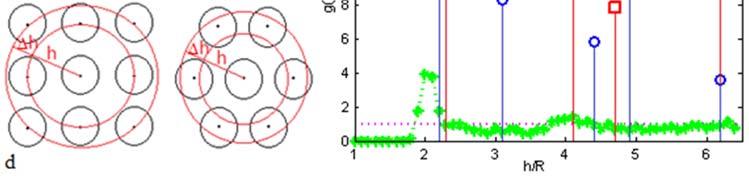
7 Fig. 2. Geometrical descriptors: (a) nearest neighbour distance, (b) nearest neighbour orientation, (c) Ripley s K function, (d) pair distribution function Ripley s K function The second order intensity function, or Ripley s K function K(h) (Fig. 2c), is one of the most informative descriptors of spatial patterns [10]. In contrast to the nearest neighbour functions, which analyse short range interactions between the fibres, K(h) provides an insight in the arrangement at a range of distances. It can be defined as a ratio between the number of points expected to lie within a radial distance h from an arbitrary point, and the number of points per unit area. For a random fibre distribution, K(h) can be estimated by [34]:, (2), where A is the area of the region, N is the total number of fibres, dij is the distance between points i and j, and I() is an indicator function having the value 1 if the condition between brackets holds true and the value 0 if the condition is false; w(li; lj) is a weight function having the value 1 if the circle with centre at point li and radius dij, i.e., passing by point lj, is completely inside the area of study. If not, w(li; lj) is the proportion of the perimeter of that circle lying in the area of study, which represents accounting for the edge effect during computing this correlation function. Ripley s K function for the Poisson (complete randomness) point pattern, KP(h), is given by K h πh (3) If the plot of K(h) is below KP(h), then there is likely some degree of vacuity of the arrangement. However, if Ripley s K function is above the Poisson curve, the distribution presents clustering. A periodic pattern provides a staircase-shaped plot of K(h). Fig.2c shows Ripley s K function curves. For the experimental set the curve stays quite close to the Poisson-curve for short distances, and for longer distances a wave-form appears. It shows that for long distances some degree of clustering and vacuity exists. For comparison, blue curves for the rectangular and hexagonal arrangement are provided. The saw-shaped form of the curves is clearly seen, which is explained by the simultaneity of capturing four or six fibre centres in the current circle for the rectangular of hexagonal packing, respectively Pair distribution function The pair distribution function g(h) (Fig. 2d) is defined as a probability of finding the centre of a fibre inside a hoop of internal radius h and thickness Δh with the centre at a randomly selected fibre, and is calculated as [11] g h n h. (4) The pair distribution function g(h) is related to Ripley s K function K(h) as follows: g h (5) This function describes the intensity of fibre distances. The hoop width is taken as Δh=0.1*R. The regular patterns exhibit sharp peaks of g(h), which are consistent with the distances between periodically arranged fibres (Fig.2d). For the Poisson point distribution, the complete randomness of the point distribution assures that g(h) = 1 for all considered distances. A statistically valid fibre distribution will have g(h) tending to 1 when the distance h increases. This is also the case for the real fibre arrangement after the strong peak at a short distance of almost touching fibres, the curve smoothly tends to value 1.
8 3.2. Mechanical statistical characterisation Similarly to the geometrical statistical investigation, nine images of real fibre distributions and nine simulated fibre distributions were generated with the same respective volume fractions. The size of the RVEs was limited to the domain equivalent to 7x7 fibres to reduce the computational effort. Taking into account the number of realisations (9) the RVE size of fibres is suggested as representative both geometrically and mechanically since the statistical gap of a single model is reduced by the number of simulations, as proposed in [35]. We analyse the stress distributions generated in these RVEs upon application of 0.3% strain in the transverse direction. The problem is solved using FE analysis in the 2D formulation under plain strain conditions and in the framework of the linear theory of elasticity. The epoxy matrix was considered as an isotropic material with Young s modulus E=3 GPa and Poisson s ratio υ=0.4. Carbon fibres were treated as transversely isotropic materials with elastic constants E1=276 GPa, E3=10.3 GPa, G23=3.8 GPa, G13=27.9 GPa, υ13=0.26, where 1 is the fibre direction. The range of volume fractions in these nine RVEs was relatively wide: from 54% to 68%. In order to avoid fibre intersections in the experimental set of fibre distributions (see section 2), the radius of overlapping fibres was reduced. According to the performed convergence analysis the minimum size of an element was set to 0.015*R at the fiber/matrix interface, where R is the fiber radius. Mechanical characterization was performed in two areas of interest: in the matrix and at the fibre/matrix interface rings (matrix elements closest to the fibre surface). In the matrix, four stresses were considered as validation functions: maximum principal stress, stress along the loading direction (σx), shear stress (σxy) and von Mises stress. At the fibre/matrix interface, the normal stress (σr) and shear stress (σrφ), with respect to local cylindrical coordinate systems placed at the fibre centres, were taken as validation functions. The importance of the interfacial stresses in the analysis of damage initiation was previously emphasized in [15, 23]. Elements at a distance of the average fibre diameter from the RVE edges or less were not included in calculation of the statistical parameters of stress fields in the matrix. This was done to avoid calculations with possible distortions of stresses on RVE boundaries in the model. Interface stresses were only accounted for fibres that lied completely inside the RVE. For quantitative statistical validation of the obtained stress fields, the probability of finding a certain stress value in a given area of interest was investigated. Stresses were calculated in the integration point of a respective element. The range of the stresses from the minimum to the maximum value was divided into a certain number of equal intervals. Then, all the elements in the area of interest (either in the matrix or at the interface) were divided in these intervals. The number of elements in each stress interval and their total volume of the elements were calculated. This way histograms were created, where the X-axis represents the stress intervals and the Y-axis is the calculated volume of the elements that the stress interval occupies in the area of interest. For illustration, three instances of the descriptors are shown in Fig 3,4, corresponding for (1) the experimental set, taken in fill-2 zone, (2) a square and (3) a hexagonal regular packing, all with VF = 67.92%. In the matrix, the curve for the maximum principal stress shows a single sharp peak for the experimental set (see Fig. 3b), which corresponds to the mean stress value in the matrix. For the rectangular, as well as for the hexagonal packings, on the other hand, two peaks are clearly seen. The two peaks are a result of the stress distribution pattern: extensive straight zones of low stresses codirectional with the load axis are side by side with periodical zones of high stresses (Fig. 3a).


.")
9 Fig. 3. Maximum principal stress in the matrix: (a) its distribution for experimental, hexagonal and rectangular fiber arrangements and (b) comparison of mechanical descriptors (Vf = 67.92%). Fig. 4c illustrates curves of normal stresses at the fibre/matrix interface. Two sharp peaks, which are seen on the hexagonal curve, reflect stress variation at the interface as a function of the angle from loading direction (Fig. 4a). Moving from 0 to 90 degree, the rate of stress change varies: for maximum and minimum stresses it is much lower than for medium stress values. For the experimental set, the trend is similar, but due to the randomness in fibre arrangement peaks are much smoother and additional tails occurred in areas of minimum and maximum stress values. For the square packing, the frequency of the normal stress is more uniform: maximum and minimum values have the same probability of occurring as the medium stresses (Fig.4b). For both areas of interests, the range of obtained stresses for the experimental set is wider than for regular packings. The random arrangement allows lower and higher distance between the fibres and hence higher and lower stresses respectively to appear. Fig. 4. Normal stress at the fibre/matrix interface: (a) in the single fibre case; (b) stress fields and (c) comparison of the experimental, hexagonal and rectangular arrangements for this stress (Vf = 67.92%)
10 4. Results and discussion: comparison of the RMG and experimental sets This section provides the quantitative description of fibre random distributions obtained from the RMG algorithm and experimental data. In every subsection below, mean values were taken for all of the nine simulated and nine experimental fibre distributions (with different fibre volume fractions). The error bars represent the maximum and the minimum values of the respective functions in these distributions. For the mechanical characterization, in each set of nine curves the curve tails were cut off by the maximum value of the left tail and minimum value of the right tail in the whole set. That was done in order to build the mean curves for each set and the interpolations of initial validation functions curves Geometrical characterization Nearest neighbours The PDF of the distance from a given fibre to its nearest neighbour is plotted in Fig.5a. The most important here is the information about the short distance fibre interaction. Fibres in both distributions are clustered and the PDF plot shows a peak for a short distance of h/r = 2 followed by a sudden decrease, but not to zero. Values of PDF at distances from h/r = 2.05 to h/r = 2.2 are higher than on the rest of the distances scale, which reflects the absence of regularity in the fibre distribution. This happens because fibres are so densely compacted against each other due to the high fibre volume fraction and because of the existence of a certain minimum distance between fibres as described before. Both curves show good correlation between each other. Fig. 5. Comparison of geometrical descriptors: (a) nearest neighbour function, (b) nearest
11 neighbour orientation function, (c) Ripley s K function, (d) pair distribution function Nearest neighbour orientations Fig.5b shows the CDF for fibre distributions obtained from experimental data and simulated by the RGM algorithm. Both curves follow the Poisson s straight line of cumulated probability. This means that the probability of finding a nearest fibre in every direction is almost equal. At some point the curve for the real microstructure deviates slightly from the Poisson s line. This is probably due to the edge effect on the real composite images explained previously. The RGM algorithm keeps the orientation of a nearest fibre almost perfectly random even for high fibre volume fractions Ripley s K function and pair distribution function Ripley s K function for the RMG algorithm distribution is represented in Fig. 5c in comparison with the same function for the real fibre arrangements. The real fibre distributions exhibit a smooth increase approaching h/r=2 from the left due to the artefact in the manual image processing as discussed earlier. The RMG-curve, on the other hand, starts right from the 2*R value and exhibits a steep increase. For short distances just above 2*R both the experimental curve and RMG-curve climb up to the Poisson s curve and then stay quite close to it and to each other. It is remarkable that the RMG curve is close to the experimental one for distances over 3R, reproducing the characteristic wave-form. For short distances the arrangement exhibits randomness, while for long distances some degree of clustering and vacuity appears. The RMG algorithm for long distances keeps itself closer to the Poisson distribution than the real curve. The pair distribution function is linked to the Ripley s K function and defined by the probability of finding the centre of a fibre inside a hoop and describes the intensity of fibre distances. Obviously a peak is expected to appear at short distances. Fig.5d shows the pair distribution function for both distributions with respect to distance. It can be seen that both experimental and simulated fibres distribution tend to value of 1, which is the pair distribution function of a perfect Poisson distribution. On the short distances both curves show the same behaviour: peaks near h/r=2. The curve for the experimental set shows a smooth increase before h/r=2 as described in section 2. Therefore the peak value of g(h) is lower than for the RMG curve. The remaining parts of the curves for both distributions show quite good correlation with each other. The remarkable fact is that on the pair distribution function graph the RMG algorithm mimics the peculiarity of the experimental curves near 4R, also seen in Ripley s K function curve (Fig 5c). This can be explained by the hexagonal clustering effect of the second ring of neighbours, which gives a certain peak right near 4R (see Fig.2c) Mechanical characterization Matrix area All validation functions computed in the matrix show certain peaks that correspond to the mean values of the respective stresses there (see Fig.6). The scatter between minimum and maximum values for the case of experimental data is significant (up to 100%). This can be partially attributed to significant variations in volume fractions from one micrograph to another (54% - 68%). If the fibre arrangements with volume fractions less than 60% and more than 63% are taken out from analysis, then the scatter reduces to the value of less than 10%. The reason why we do not see such significant scatter in error bars for the RMG curve is that this algorithm is based on pure random Poisson point distribution and heuristic method of moving fibres. Hence it generates well distributed fibre arrangements and cannot create large matrix rich zones within the fibre package.
12 Fig. 6. Comparison of mechanical descriptors (in the matrix): (a) maximum principal stress, (b) Sx stress, (c) von Mises stress, (d) shear Sxy stress. Apart from these effects related to the volume fraction variation, the mean curves obtained from the experimental set and the RMG algorithm almost coincide. In the matrix all considered validation functions behave the same way. It can be concluded that the distributions are statistically equivalent from the point of view of generated stresses Fibre/matrix interface area Fig.7a shows mean curves for distribution of the normal stress at the fibre-matrix interface. As it was explained earlier, we expect to see double-peaked curves. It is clearly seen that their behaviour is similar to the single fibre case (Fig. 4a), under the correction of the arrangement randomness, which leads to flowing decrease of curves from both sides of saddle. The RMG-curve correlates with the experimental curve very well. The same behaviour is observed for the shear stress graph (Fig.7b). Figs.7c,d represent the maximum values of the normal and shear stresses captured in every interface ring. The large error bars may be attributed to the previously mentioned scatter in the fiber volume fractions in the RVEs or to a limited number of the considered fibers (20-25 fibres that are completely inside the RVE). The latter would make the influence of the random inter-fibre distance stronger. One peculiar observation can be made about the mean curves. The maximum value in the RMG-curves in every single graph is higher than the maximum value in the corresponding curve from the micrograph. It appears as if the RMG-curve is simply shifted forward from the experimental curve (Fig.7c). This can be explained by the fact that the RMG algorithm generates fibres that are closer to each other: the probability of finding a nearest fibre centre at a distance less than 2.05*radius to a given fibre centre is 7.7% higher than for the case of real microstructures (Fig. 5a). It can be concluded, that using the RMG
: (a) normal stress, (b) shear stress, (c) maximum normal stress, (d) maximum shear stress. 5.")
13 algorithm the critical stresses will be overestimated in comparison with the real fibre microstructures thus providing a small margin for the safety-factor. Fig. 7. Comparison of mechanical descriptors (at the fiber/matrix interface): (a) normal stress, (b) shear stress, (c) maximum normal stress, (d) maximum shear stress. 5. Conclusions An adequate representation of microstructures in fiber-reinforced composites is of critical importance for the analysis of the damage onset and propagation. In the present work, the heuristic random microstructure generation (RMG) algorithm proposed in [28] was investigated on the subject of its suitability to generate fiber arrangements encountered in real composites. The algorithm was used in its original form with a small modification applied to the minimum allowable distance between fibers, which was set to be randomly varying in a certain range. Nine simulated and nine generated fibre arrangements with fiber volume fractions ranging between 58% and 68% were compared using statistical descriptors. For the geometrical characterization the nearest neighbour distance, nearest neighbour orientation, Ripley s K function and pair distribution function were considered. For the mechanical characterization stresses in the matrix and at the fiber/matrix interfaces were analyzed. From the study it was concluded that the RMG algorithm creates fiber arrangements that are statistically equivalent to real fibre distributions found in UD tows of a 3D woven non-crimp carbon fiber/epoxy composites. The algorithm can, therefore, be used for the definition of 3D micromechanical finite element models of UD composites to simulate damage development.
14 Acknowledgements Composites: Science and Technology 87 (2013) p The work leading to this publication has received funding from the European Union Seventh Framework Programme (FP7), as part of the project IMS&CPS. The authors thank P. Camanho and A.R. Melro from the University of Porto for the permission to use their random fibre packing generator for research purposes. References 1. Wongsto, A. and S. Li, Micromechanical FE analysis of UD fibre-reinforced composites with fibres distributed at random over the transverse cross-section. Composites Part a-applied Science and Manufacturing, (9): p Aghdam, M.M. and A. Dezhsetan, Micromechanics based analysis of randomly distributed fiber reinforced composites using simplified unit cell model. Composite Structures, (3-4): p Bulsara, V.N., R. Talreja, and J. Qu, Damage initiation under transverse loading of unidirectional composites with arbitrarily distributed fibers. Composites Science and Technology, (5): p Gusev, A.A., P.J. Hine, and I.M. Ward, Fiber packing and elastic properties of a transversely random unidirectional glass/epoxy composite. Composites Science and Technology, (4): p Knight, M.G., L.C. Wrobel, and J.L. Henshall, Micromechanical response of fibre-reinforced materials using the boundary element technique. Composite Structures, (3-4): p Rossoll, A., B. Moser, and A. Mortensen, Longitudinal deformation of fibre reinforced metals: influence of fibre distribution on stiffness and flow stress. Mechanics of Materials, (1): p Trias, D., et al., Random models versus periodic models for fibre reinforced composites. Computational Materials Science, (2): p Brockenbrough, J.R., S. Suresh, and H.A. Wienecke, Deformation of metal-matrix composites with continuous fibers - geometrical effects of fiber distribution and shape. Acta Metallurgica Et Materialia, (5): p Pyrz, R., Correlation of microstructure variability and local stress-field in 2-phase materials. Materials Science and Engineering a-structural Materials Properties Microstructure and Processing, (1-2): p Pyrz, R., Quantitative description of the microstructure of composites.1. Morphology of unidirectional composite systems. Composites Science and Technology, (2): p Matsuda, T., et al., Effects of fiber distribution on elastic-viscoplastic behavior of long fiberreinforced laminates. International Journal of Mechanical Sciences, (10): p Maligno, A.R., N.A. Warrior, and A.C. Long, Effects of inter-fibre spacing on damage evolution in unidirectional (UD) fibre-reinforced composites. European Journal of Mechanics a-solids, (4): p Romanowicz, M., Progressive failure analysis of unidirectional fiber-reinforced polymers with inhomogeneous interphase and randomly distributed fibers under transverse tensile loading. Composites Part a-applied Science and Manufacturing, (12): p Yang, S., A. Tewari, and A.M. Gokhale, Modeling of non-uniform spatial arrangement of fibers in a ceramic matrix composite. Acta Materialia, (7): p
15 15. Hojo, M., et al., Effect of fiber array irregularities on microscopic interfacial normal stress states of transversely loaded UD-CFRP from viewpoint of failure initiation. Composites Science and Technology, (11-12): p Trias, D., et al., A two-scale method for matrix cracking probability in fibre-reinforced composites based on a statistical representative volume element. Composites Science and Technology, (11-12): p Swaminathan, S., S. Ghosh, and N.J. Pagano, Statistically equivalent representative volume elements for unidirectional composite microstructures: Part I - Without damage. Journal of Composite Materials, (7): p Stoyan, D., W.S. Kendall, and J. Mecke, Stochastic geometry and its applications. 2nd ed. Wiley series in probability and statistics Applied probability and statistics. 1995, Chichester ; New York: Wiley. xix, 436 p. 19. Buryachenko, V.A., et al., Quantitative description and numerical simulation of random microstructures of composites and their effective elastic moduli. International Journal of Solids and Structures, (1): p Oh, J.H., K.K. Jin, and S.K. Ha, Interfacial strain distribution of a unidirectional composite with randomly distributed fibers under transverse loading. Journal of Composite Materials, (9): p Feder, J., Random sequential adsorption. Journal of Theoretical Biology, (2): p Grishanov, S.A., et al., The simulation of the geometry of a two-component yarn - Part II: Fibre distribution in the yarn cross-section. Journal of the Textile Institute, (4): p Chen, X.M. and T.D. Papathanasiou, Interface stress distributions in transversely loaded continuous fiber composites: parallel computation in multi-fiber RVEs using the boundary element method. Composites Science and Technology, (9): p Zhenqing, W., et al., Automatic generation of random distribution of fibers in long-fiberreinforced composites and mesomechanical simulation. Materials & Design, (2): p Jodrey, W.S. and E.M. Tory, Computer-simulation of close random packing of equal spheres. Physical Review A, (4): p Vaughan, T.J. and C.T. McCarthy, A combined experimental-numerical approach for generating statistically equivalent fibre distributions for high strength laminated composite materials. Composites Science and Technology, (2): p Yang, L., et al., A new method for generating random fibre distributions for fibre reinforced composites. Composites Science and Technology, : p Melro, A.R., P.P. Camanho, and S.T. Pinho, Generation of random distribution of fibres in long-fibre reinforced composites. Composites Science and Technology, (9): p Karahan, M., et al., Internal geometry evaluation of non-crimp 3D orthogonal woven carbon fabric composite. Composites Part A: Applied Science and Manufacturing, (9): p Shan, Z.H. and A.M. Gokhale, Representative volume element for non-uniform micro-structure. Computational Materials Science, (3): p Trias, D., et al., Determination of the critical size of a statistical representative volume element (SRVE) for carbon reinforced polymers. Acta Materialia, (13): p Torquato, S., Random heterogeneous materials: microstructure and macroscopic properties.. Interdisciplinary Applied Science. 2001: Springer 33. Illian, J., et al., Statistical Analysis and Modelling of Spatial Point Patterns. 2008, John Wiley & Sons, Ltd. p
16 34. Dixon, P.M., Ripley's K Function, in Encyclopedia of Environmetrics. 2006, John Wiley & Sons, Ltd. 35. Y. Fujita, T.K., A proposal of FE modeling of unidirectional composite considering uncertain microstructure, in 18th Iternational Conference on Composite Materials ( ICCM18). 2011: Jeju Island, Korea.
PREDICTION OF TENSILE STIFFNESS AND FAILURE OF CARBON FIBRE COMPOSITE LAMINAE: A MULTI-SCALE NON-DETERMINISTIC APPROACH
 Athens, Greece, 24-28 th June 2018 1 PREDICTION OF TENSILE STIFFNESS AND FAILURE OF CARBON FIBRE COMPOSITE LAMINAE: A MULTI-SCALE NON-DETERMINISTIC APPROACH F. Malgioglio 1,2*, F. Mesquita 2, C. Breite
Nanoindentation of Fibrous Composite Microstructures: Experimentation and Finite Element Investigation. Mark Hardiman
 Nanoindentation of Fibrous Composite Microstructures: Experimentation and Finite Element Investigation Mark Hardiman Materials and Surface Science Institute (MSSI), Department of Mechanical and Aeronautical
Determination of the minimum size of a statistical representative volume element from a fibre-reinforced composite based on point pattern statistics
 Downloaded from orbit.dtu.dk on: Dec 04, 2018 Determination of the minimum size of a statistical representative volume element from a fibre-reinforced composite based on point pattern statistics Hansen,
Micromechanical analysis of FRP hybrid composite lamina for in-plane transverse loading
 Indian Journal of Engineering & Materials Sciences Vol. 15, October 2008, pp. 382-390 Micromechanical analysis of FRP hybrid composite lamina for in-plane transverse loading K Sivaji Babu a *, K Mohana
MESO-SCALE MODELLING IN THERMOPLASTIC 5-HARNESS SATIN WEAVE COMPOSITE
 MESO-SCALE MODELLING IN THERMOPLASTIC 5-HARNESS SATIN WEAVE COMPOSITE S. Daggumati a*,i. De Baere a, W. Van Paepegem a, J. Degrieck a, J. Xu b, S.V. Lomov b, I. Verpoest b a Ghent University, Dept. of
Mechanical and Thermal Properties of Coir Fiber Reinforced Epoxy Composites Using a Micromechanical Approach
 Mechanical and Thermal Properties of Coir Fiber Reinforced Epoxy Composites Using a Micromechanical Approach Sandhyarani Biswas Department of Mechanical Engineering, N.I.T Rourkela, INDIA Abstract: Now-a-days,
MICROMECHANICAL ANALYSIS OF FRP COMPOSITES SUBJECTED TO LONGITUDINAL LOADING
 MICROMECHANICAL ANALYSIS OF FRP COMPOSITES SUBJECTED TO LONGITUDINAL LOADING N. Krishna Vihari 1, P. Phani Prasanthi 1, V. Bala Krishna Murthy 2* and A. Srihari Prasad 3 1 Mech. Engg. Dept., P. V. P. Siddhartha
INVESTIGATION OF THE PROCESSING PARAMETERS OF A 3D WOVEN REINFORCEMENT
 INVESTIGATION OF THE PROCESSING PARAMETERS OF A 3D WOVEN REINFORCEMENT Andreas Endruweit, Dhiren K. Modi and Andrew C. Long School of Mechanical, Materials and Manufacturing Engineering, University of
EVALUATION OF DAMAGE DEVELOPMENT FOR NCF COMPOSITES WITH A CIRCULAR HOLE BASED ON MULTI-SCALE ANALYSIS
 THE 19 TH INTERNATIONAL CONFERENCE ON COMPOSITE MATERIALS EVALUATION OF DAMAGE DEVELOPMENT FOR NCF COMPOSITES WITH A CIRCULAR HOLE BASED ON MULTI-SCALE ANALYSIS T. Kurashiki 1 *, Y. Matsushima 1, Y. Nakayasu
CHEM-E2200: Polymer blends and composites Fibre architecture and principles of reinforcement
 CHEM-E2200: Polymer blends and composites Fibre architecture and principles of reinforcement Mark Hughes 19 th September 2016 Outline Fibre architecture Volume fraction and the rule of mixtures Principle
Prediction of Micromechanical Behaviour of Elliptical Frp Composites
 Prediction of Micromechanical Behaviour of Elliptical Frp Composites Kiranmayee.Nerusu Dept. of Mechanical Engg. P. V. P. Siddhartha Institute of Technology, Vijayawada 520 007, A.P, India. P. Phani Prasanthi
Towards Affordable, Closed-Loop Recyclable Future Low Carbon Vehicles. Supervisors : Dr. L.T. Harper, Dr. M. Johnson, Prof. N.A.
 Towards Affordable, Closed-Loop Recyclable Future Low Carbon Vehicles Supervisors : Dr. L.T. Harper, Dr. M. Johnson, Prof. N.A. Warrior Moulding issues with CF/PP Now looking to use CF/PA6 consolidation
Computational Analysis for Composites
 Computational Analysis for Composites Professor Johann Sienz and Dr. Tony Murmu Swansea University July, 011 The topics covered include: OUTLINE Overview of composites and their applications Micromechanics
CHEM-C2410: Materials Science from Microstructures to Properties Composites: basic principles
 CHEM-C2410: Materials Science from Microstructures to Properties Composites: basic principles Mark Hughes 14 th March 2017 Today s learning outcomes To understand the role of reinforcement, matrix and
ScienceDirect. Unit cell model of woven fabric textile composite for multiscale analysis. Anurag Dixit a *,Harlal Singh Mali b, R.K.
 Available online at www.sciencedirect.com ScienceDirect Procedia Engineering 68 ( 2013 ) 352 358 The Malaysian International Tribology Conference 2013 (MITC2013) Unit cell model of woven fabric textile
*Corresponding author: Keywords: Finite-element analysis; Multiscale modelling; Onset theory; Dilatational strain invariant.
 18 TH INTERNATIONAL CONFERENCE ON COMPOSITE MATERIALS MICROMECHANICAL MODELLING OF TEST SPECIMENS FOR ONSET OF DILATATIONAL DAMAGE OF POLYMER MATRIX IN COMPOSITE MATERIALS T. D. Tran 1, D. Kelly 1*, G.
Keywords: computer aided engineering, finite element analysis, multi scale modelling, fatigue life prediction
 16 TH INTERNATIONAL CONFERENCE ON COMPOSITE MATERIALS 3D TEXTILE COMPOSITE MECHANICAL PROPERTIES Jonathan J. Crookston, Sreedhar Kari, Nicholas A. Warrior, I. Arthur Jones & Andrew C. Long University of
Stress-strain response and fracture behaviour of plain weave ceramic matrix composites under uni-axial tension, compression or shear
 Xi an 2-25 th August 217 Stress-strain response and fracture behaviour of plain weave ceramic matrix composites under uni-axial tension compression or shear Heyin Qi 1 Mingming Chen 2 Yonghong Duan 3 Daxu
Modelling the nonlinear shear stress-strain response of glass fibrereinforced composites. Part II: Model development and finite element simulations
 Modelling the nonlinear shear stress-strain response of glass fibrereinforced composites. Part II: Model development and finite element simulations W. Van Paepegem *, I. De Baere and J. Degrieck Ghent
2 Experiment of GFRP bolt
 16 TH INTERNATIONAL CONFERENCE ON COMPOSITE MATERIALS FATIGUE LIFE EVALUATION OF BOLT MADE OF WOVEN FABRIC FRP Takeshi INOUE*, Hiroaki NAKAI**, Tetsusei KURASHIKI**, Masaru ZAKO**, Yuji KOMETANI*** *Graduate
Prediction of Elastic Constants on 3D Four-directional Braided
 Prediction of Elastic Constants on 3D Four-directional Braided Composites Prediction of Elastic Constants on 3D Four-directional Braided Composites Liang Dao Zhou 1,2,* and Zhuo Zhuang 1 1 School of Aerospace,
Statistically Equivalent Representative Volume Elements for Unidirectional Composite Microstructures: Part I Without Damage
 Statistically Equivalent Representative Volume Elements for Unidirectional Composite Microstructures: Part I Without Damage SHRIRAM SWAMINATHAN, 1 SOMNATH GHOSH 1, * AND N. J. PAGANO 1,2 1 Department of
A FINITE ELEMENT MODEL TO PREDICT MULTI- AXIAL STRESS-STRAIN RESPONSE OF CERAMIC MATRIX COMPOSITES WITH STRAIN INDUCED DAMAGE
 A FINITE ELEMENT MODEL TO PREDICT MULTI- AXIAL STRESS-STRAIN RESPONSE OF CERAMIC MATRIX COMPOSITES WITH STRAIN INDUCED DAMAGE Daxu Zhang and D. R. Hayhurst School of Mechanical, Aerospace and Civil Engineering,
DAMAGE MECHANICS MODEL FOR OFF-AXIS FATIGUE BEHAVIOR OF UNIDIRECTIONAL CARBON FIBER-REINFORCED COMPOSITES AT ROOM AND HIGH TEMPERATURES
 DAMAGE MECHANICS MODEL FOR OFF-AXIS FATIGUE BEHAVIOR OF UNIDIRECTIONAL CARBON FIBER-REINFORCED COMPOSITES AT ROOM AND HIGH TEMPERATURES M. Kawai Institute of Engineering Mechanics University of Tsukuba,
Influence of the filament winding process variables on the mechanical behavior of a composite pressure vessel
 Influence of the filament winding process variables on the mechanical behavior of a composite pressure vessel G. Vargas 1 & A. Miravete 2 1 Universidad Pontificia Bolivariana, Facultad de Ingeniería Mecánica,
BIAXIAL STRENGTH INVESTIGATION OF CFRP COMPOSITE LAMINATES BY USING CRUCIFORM SPECIMENS
 BIAXIAL STRENGTH INVESTIGATION OF CFRP COMPOSITE LAMINATES BY USING CRUCIFORM SPECIMENS H. Kumazawa and T. Takatoya Airframes and Structures Group, Japan Aerospace Exploration Agency 6-13-1, Ohsawa, Mitaka,
Micro-meso draping modelling of non-crimp fabrics
 Micro-meso draping modelling of non-crimp fabrics Oleksandr Vorobiov 1, Dr. Th. Bischoff 1, Dr. A. Tulke 1 1 FTA Forschungsgesellschaft für Textiltechnik mbh 1 Introduction Non-crimp fabrics (NCFs) are
Module III - Macro-mechanics of Lamina. Lecture 23. Macro-Mechanics of Lamina
 Module III - Macro-mechanics of Lamina Lecture 23 Macro-Mechanics of Lamina For better understanding of the macromechanics of lamina, the knowledge of the material properties in essential. Therefore, the
Module 7: Micromechanics Lecture 34: Self Consistent, Mori -Tanaka and Halpin -Tsai Models. Introduction. The Lecture Contains. Self Consistent Method
 Introduction In this lecture we will introduce some more micromechanical methods to predict the effective properties of the composite. Here we will introduce expressions for the effective properties without
Meso-scale Modeling of Static and Fatigue Damage in Woven Composite Materials with Finite Element Method
 Meso-scale Modeling of Static and Fatigue Damage in Woven Composite Materials with Finite Element Method J. Xu a*, SV. Lomov a, I. Verpoest a, S. Daggumati b, W. Van Paepegem b, J. Degrieck b a Katholieke
Numerical evaluation of effective material properties of randomly distributed short cylindrical fibre composites
 Computational Materials Science 39 (2007) 198 204 www.elsevier.com/locate/commatsci Numerical evaluation of effective material properties of randomly distributed short cylindrical fibre composites S. Kari
Module 4: Behaviour of a Laminae-II. Learning Unit 1: M1. M4.1 Mechanics of Composites. M4.1.1 Introduction to Mechanics of Composites
 Module 4: Behaviour of a Laminae-II Learning Unit 1: M1 M4.1 Mechanics of Composites M4.1.1 Introduction to Mechanics of Composites The relation between ply uniaxial strengths and constituent properties
Non-conventional Glass fiber NCF composites with thermoset and thermoplastic matrices. F Talence, France Le Cheylard, France
 20 th International Conference on Composite Materials Copenhagen, 19-24th July 2015 Non-conventional Glass fiber NCF composites with thermoset and thermoplastic matrices. Thierry Lorriot 1, Jalal El Yagoubi
Enhancing Prediction Accuracy In Sift Theory
 18 TH INTERNATIONAL CONFERENCE ON COMPOSITE MATERIALS Enhancing Prediction Accuracy In Sift Theory J. Wang 1 *, W. K. Chiu 1 Defence Science and Technology Organisation, Fishermans Bend, Australia, Department
KINK BAND FORMATION OF FIBER REINFORCED POLYMER (FRP)
") KINK BAND FORMATION OF FIBER REINFORCED POLYMER (FRP) 1 University of Science & Technology Beijing, China, niukm@ustb.edu.cn 2 Tsinghua University, Department of Engineering Mechanics, Beijing, China,
KINK BAND FORMATION OF FIBER REINFORCED POLYMER (FRP) 1 University of Science & Technology Beijing, China, niukm@ustb.edu.cn 2 Tsinghua University, Department of Engineering Mechanics, Beijing, China,
Finite Element Modeling of Residual Thermal Stresses in Fiber-Reinforced Composites Using Different Representative Volume Elements
 Proceedings o the World Congress on Engineering 21 Vol II WCE 21, June 3 - July 2, 21, London, U.K. Finite Element Modeling o Residual Thermal Stresses in Fiber-Reinorced Composites Using Dierent Representative
In-situ local strain measurement in textile composites with embedded optical fibre sensors
 In-situ local strain measurement in textile composites with embedded optical fibre sensors S. Daggumati, E. Voet, I. De Baere, W. Van Paepegem & J. Degrieck Ghent University, Department of Materials Science
Composites Science and Technology
 Composites Science and Technology 7 (1) 194 1941 Contents lists available at ScienceDirect Composites Science and Technology journal homepage: www.elsevier.com/locate/compscitech Local damage in a 5-harness
Effect of fibre shape on transverse thermal conductivity of unidirectional composites
 Sādhanā Vol. 4, Part 2, April 25, pp. 53 53. c Indian Academy of Sciences Effect of fibre shape on transverse thermal conductivity of unidirectional composites B RAGHAVA RAO,, V RAMACHANDRA RAJU 2 and
Multi Disciplinary Delamination Studies In Frp Composites Using 3d Finite Element Analysis Mohan Rentala
 Multi Disciplinary Delamination Studies In Frp Composites Using 3d Finite Element Analysis Mohan Rentala Abstract: FRP laminated composites have been extensively used in Aerospace and allied industries
Coupling of plasticity and damage in glass fibre reinforced polymer composites
 EPJ Web of Conferences 6, 48 1) DOI: 1.151/epjconf/1648 c Owned by the authors, published by EDP Sciences, 1 Coupling of plasticity and damage in glass fibre reinforced polymer composites R. Kvale Joki
MESH MODELING OF ANGLE-PLY LAMINATED COMPOSITE PLATES FOR DNS AND IPSAP
 16 TH INTERNATIONAL CONFERENCE ON COMPOSITE MATERIALS MESH MODELING OF ANGLE-PLY LAMINATED COMPOSITE PLATES FOR DNS AND IPSAP Wanil Byun*, Seung Jo Kim*, Joris Wismans** *Seoul National University, Republic
SOME RESEARCH ON FINITE ELEMENT ANALYSIS OF COMPOSITE MATERIALS
 Mechanical Testing and Diagnosis ISSN 2247 9635, 2012 (II), Volume 3, 79-85 SOME RESEARCH ON FINITE ELEMENT ANALYSIS OF COMPOSITE MATERIALS Valeriu DULGHERU, Viorel BOSTAN, Marin GUŢU Technical University
DEVELOPMENT OF A MICROMECHANICAL MODEL IN INTERACTION WITH PARAMETERS RELATED TO THE MICROSTRUCTURE OF CARBON/EPOXY COMPOSITES
 ECCM16-16 TH EUROPEAN CONFERENCE ON COMPOSITE MATERIALS, Seville, Spain, 22-26 June 2014 DEVELOPMENT OF A MICROMECHANICAL MODEL IN INTERACTION WITH PARAMETERS RELATED TO THE MICROSTRUCTURE OF CARBON/EPOXY
PREDICTION OF OUT-OF-PLANE FAILURE MODES IN CFRP
 PREDICTION OF OUT-OF-PLANE FAILURE MODES IN CFRP R. R. Pinto 1, P. P. Camanho 2 1 INEGI - Instituto de Engenharia Mecanica e Gestao Industrial, Rua Dr. Roberto Frias, 4200-465, Porto, Portugal 2 DEMec,
Composite models 30 and 131: Ply types 0 and 8 calibration
 Model calibration Composite Bi-Phase models 30 and 3 for elastic, damage and failure PAM-CRASH material model 30 is for solid and 3 for multi-layered shell elements. Within these models different ply types
PREDICTING THE CONSTITUTIVE BEHAVIOR OF BIAXIAL BRAIDED COMPOSITES USING BEAM UNIT CELLS
 THE 19TH INTERNATIONAL CONFERENCE ON COMPOSITE MATERIALS PREDICTING THE CONSTITUTIVE BEHAVIOR OF BIAXIAL 1 J. Cichosz1*, J. Bückle1, R. Hinterhölzl1, M. Wolfahrt2 Institute for Carbon Composites, Technische
FINITE ELEMENT ANALYSIS OF A LAYERED COMPOSITE CYLINDER USING THE CONNECTION BETWEEN THE MACRO- AND MICROSTRUCTURE
 FINITE ELEMENT ANALYI OF A LAYERED COMPOITE CYLINDER UING THE CONNECTION BETWEEN THE MACRO- AND MICROTRUCTURE A. zekrényes Research Assistant, Department of Applied Mechanics, Budapest University of Technology
Effects of mesostructure on the in-plane properties of tufted carbon fabric composites
 Effects of mesostructure on the in-plane properties of tufted carbon fabric composites CompTest 2011, 14 th February 2011 Johannes W G Treiber Denis D R Cartié Ivana K Partridge j.treiber@cranfield.ac.uk
DESIGN OF LAMINATES FOR IN-PLANE LOADING
 DESIGN OF LAMINATES FOR IN-PLANOADING G. VERCHERY ISMANS 44 avenue F.A. Bartholdi, 72000 Le Mans, France Georges.Verchery@m4x.org SUMMARY This work relates to the design of laminated structures primarily
Practice Final Examination. Please initial the statement below to show that you have read it
 EN175: Advanced Mechanics of Solids Practice Final Examination School of Engineering Brown University NAME: General Instructions No collaboration of any kind is permitted on this examination. You may use
FIBRE WAVINESS INDUCED BENDING IN COMPRESSION TESTS OF UNIDERECTIONAL NCF COMPOSITES
 FIBRE WAVINESS INDUCED BENDING IN COMPRESSION TESTS OF UNIDERECTIONAL NCF COMPOSITES Dennis Wilhelmsson 1, Leif E. Asp 1, Renaud Gutkin 2, Fredrik Edgren 3 1 Chalmers University of Technology, Dept. Industrial
Stress and Displacement Analysis of a Rectangular Plate with Central Elliptical Hole
 Stress and Displacement Analysis of a Rectangular Plate with Central Elliptical Hole Dheeraj Gunwant, J. P. Singh mailto.dheerajgunwant@gmail.com, jitenderpal2007@gmail.com, AIT, Rampur Abstract- A static
5. STRESS CONCENTRATIONS. and strains in shafts apply only to solid and hollow circular shafts while they are in the
 5. STRESS CONCENTRATIONS So far in this thesis, most of the formulas we have seen to calculate the stresses and strains in shafts apply only to solid and hollow circular shafts while they are in the elastic
MICROMECHANICAL FAILURE ANALYSIS OF UNIDIRECTIONAL FIBER-REINFORCED COMPOSITES UNDER IN-PLANE AND TRANSVERSE SHEAR
 THE 19 TH INTERNATIONAL CONFERENCE ON COMPOSITE MATERIALS MICROMECHANICAL FAILURE ANALYSIS OF UNIDIRECTIONAL FIBER-REINFORCED COMPOSITES UNDER IN-PLANE AND TRANSVERSE SHEAR Lei Yang*, Ying Yan, Zhiguo
The concept of Representative Volume for elastic, hardening and softening materials
 The concept of Representative Volume for elastic, hardening and softening materials Inna M. Gitman Harm Askes Lambertus J. Sluys Oriol Lloberas Valls i.gitman@citg.tudelft.nl Abstract The concept of the
Open-hole compressive strength prediction of CFRP composite laminates
 Open-hole compressive strength prediction of CFRP composite laminates O. İnal 1, A. Ataş 2,* 1 Department of Mechanical Engineering, Balikesir University, Balikesir, 10145, Turkey, inal@balikesir.edu.tr
Fig. 1. Circular fiber and interphase between the fiber and the matrix.
 Finite element unit cell model based on ABAQUS for fiber reinforced composites Tian Tang Composites Manufacturing & Simulation Center, Purdue University West Lafayette, IN 47906 1. Problem Statement In
MULTI-SCALE MODELLING OF FIBRE BUNDLES
 THE 19 TH INTERNATIONAL CONFERENCE ON COMPOSITE MATERIALS MULTI-SCALE MODELLING OF FIBRE BUNDLES N. D. Chakladar 1, P. Mandal 1 *, P. Potluri 2 1 School of Mechanical, Aerospace and Civil Engineering,
Calculation of Damage-dependent Directional Failure Indices from the Tsai-Wu Static Failure Criterion
 Van Paepegem, W. and Degrieck, J. (3. alculation of Damage-dependent Directional Failure Indices from the sai-wu Static Failure riterion. omposites Science and echnology, 63(, 35-3. alculation of Damage-dependent
QUESTION BANK Composite Materials
 QUESTION BANK Composite Materials 1. Define composite material. 2. What is the need for composite material? 3. Mention important characterits of composite material 4. Give examples for fiber material 5.
ISSN: ISO 9001:2008 Certified International Journal of Engineering Science and Innovative Technology (IJESIT) Volume 2, Issue 4, July 2013
 Volume 2, Issue 4, July 2013") Delamination Studies in Fibre-Reinforced Polymer Composites K.Kantha Rao, Dr P. Shailesh, K. Vijay Kumar 1 Associate Professor, Narasimha Reddy Engineering College Hyderabad. 2 Professor, St. Peter s Engineering
Delamination Studies in Fibre-Reinforced Polymer Composites K.Kantha Rao, Dr P. Shailesh, K. Vijay Kumar 1 Associate Professor, Narasimha Reddy Engineering College Hyderabad. 2 Professor, St. Peter s Engineering
Module 7: Micromechanics Lecture 29: Background of Concentric Cylinder Assemblage Model. Introduction. The Lecture Contains
 Introduction In this lecture we are going to introduce a new micromechanics model to determine the fibrous composite effective properties in terms of properties of its individual phases. In this model
Overview of Probabilistic Modeling of Woven Ceramic Matrix Composites ABSTRACT
 ABSTRACT An overview of current research efforts in understanding the cause of variability in the thermo-mechanical properties of woven ceramic matrix composites is presented. Statistical data describing
An integrated approach to the design of high performance carbon fibre reinforced risers - from micro to macro - scale
 An integrated approach to the design of high performance carbon fibre reinforced risers - from micro to macro - scale Angelos Mintzas 1, Steve Hatton 1, Sarinova Simandjuntak 2, Andrew Little 2, Zhongyi
FINITE ELEMENT ANALYSIS OF COMPOSITE MATERIALS
 FINITE ELEMENT ANALYSIS OF COMPOSITE MATERIALS Ever J. Barbero Department of Mechanical and Aerospace Engineering West Virginia University USA CRC Press Taylor &.Francis Group Boca Raton London New York
Buckling Behavior of 3D Randomly Oriented CNT Reinforced Nanocomposite Plate
 Buckling Behavior of 3D Randomly Oriented CNT Reinforced Nanocomposite Plate Outline Introduction Representative Volume Element (RVE) Periodic Boundary Conditions on RVE Homogenization Method Analytical
Effect of Thermal Stresses on the Failure Criteria of Fiber Composites
 Effect of Thermal Stresses on the Failure Criteria of Fiber Composites Martin Leong * Institute of Mechanical Engineering Aalborg University, Aalborg, Denmark Bhavani V. Sankar Department of Mechanical
Chapter 7. Highlights:
 Chapter 7 Highlights: 1. Understand the basic concepts of engineering stress and strain, yield strength, tensile strength, Young's(elastic) modulus, ductility, toughness, resilience, true stress and true
Prediction of The Ultimate Strength of Composite Laminates Under In-Plane Loading Using A Probabilistic Approach
 Prediction of the Ultimate Strength of Composite Laminates Under In-Plane Loading Prediction of The Ultimate Strength of Composite Laminates Under In-Plane Loading Using A Probabilistic Approach Tae Jin
TENSILE FATIGUE BEHAVIOR OF SINGLE FIBRES AND FIBRE BUNDLES
 TENSILE FATIGUE BEHAVIOR OF SINGLE FIBRES AND FIBRE BUNDLES C. Qian 1 *, R. P. L. Nijssen 1, D. D. Samborsky 2, C.Kassapoglou 3, Z. Gürdal 3, G. Q. Zhang 4 1 Knowledge Centre Wind turbine Materials and
Stress, Strain Stress strain relationships for different types of materials Stress strain relationships for a unidirectional/bidirectional lamina
 Chapter 2 Macromechanical Analysis of a Lamina Stress, Strain Stress strain relationships for different types of materials Stress strain relationships for a unidirectional/bidirectional lamina Islamic
THE ROLE OF DELAMINATION IN NOTCHED AND UNNOTCHED TENSILE STRENGTH
 THE ROLE OF DELAMINATION IN NOTCHED AND UNNOTCHED TENSILE STRENGTH M. R. Wisnom University of Bristol Advanced Composites Centre for Innovation and Science University Walk, Bristol BS8 1TR, UK M.Wisnom@bristol.ac.uk
EFFECT OF THERMAL FATIGUE ON INTRALAMINAR CRACKING IN LAMINATES LOADED IN TENSION
 EFFECT OF THERMAL FATIGUE ON INTRALAMINAR CRACKING IN LAMINATES LOADED IN TENSION J.Varna and R.Joffe Dept of Applied Physics and Mechanical Engineering Lulea University of Technology, SE 97187, Lulea,
Don Robbins, Andrew Morrison, Rick Dalgarno Autodesk, Inc., Laramie, Wyoming. Abstract
 PROGRESSIVE FAILURE SIMULATION OF AS-MANUFACTURED SHORT FIBER FILLED INJECTION MOLDED PARTS: VALIDATION FOR COMPLEX GEOMETRIES AND COMBINED LOAD CONDITIONS Don Robbins, Andrew Morrison, Rick Dalgarno Autodesk,
STOCHASTIC MULTI-SCALE MODELLING OF SHORT- AND LONG-RANGE EFFECTS IN TEXTILE COMPOSITES BASED ON EXPERIMENTAL DATA
 STOCHASTIC MULTI-SCALE MODELLING OF SHORT- AND LONG-RANGE EFFECTS IN TEXTILE COMPOSITES BASED ON EXPERIMENTAL DATA A. Vanaerschot 1, B. N. Cox 2, S. V. Lomov 3, D. Vandepitte 1 1 KU Leuven, Dept. of Mechanical
Most of the material in this package is based on a recently published book. This is:
 Mechanics of Composite Materials Version 2.1 Bill Clyne, University of Cambridge Boban Tanovic, MATTER Assumed Pre-knowledge It is assumed that the student is familiar with simple concepts of mechanical
Effects of geometry and properties of fibre and matrix on overall. composite parameters
 Int. Journal of Applied Sciences and ngineering Research, ol. 3, Issue 4, 2014 www.ijaser.com 2014 by the authors Licensee IJASR- Under Creative Commons License 3.0 editorial@ijaser.com Research article
DIGIMAT for NANO-COMPOSITES
 DIGIMAT for NANO-COMPOSITES Document Version 2.0.1, February 2010 info@e-xstream.com www.e-xstream.com Materials: Engineering Plastics, Reinforced Plastics, Mineral and Clay fillers. e-xstream Technology:
EVALUATION OF GLASS FIBER/EPOXY INTERFACIAL STRENGTH USING A CRUCIFORM SPECIMEN
 6 TH INTERNATIONAL CONFERENCE ON COMPOSITE MATERIALS EVALUATION OF GLASS FIBER/EPOXY INTERFACIAL STRENGTH USING A CRUCIFORM SPECIMEN Shinji Ogihara*, Yoriaki Sakamoto ** and Hajime Kato ** *Department
MODELING OF THE BEHAVIOR OF WOVEN LAMINATED COMPOSITES UNTIL RUPTURE
 MODELING OF THE BEHAVIOR OF WOVEN LAMINATED COMPOSITES UNTIL RUPTURE Jean Paul Charles, Christian Hochard,3, Pierre Antoine Aubourg,3 Eurocopter, 375 Marignane cedex, France Unimeca, 6 rue J. Curie, 3453
Discrete Element Modelling of a Reinforced Concrete Structure
 Discrete Element Modelling of a Reinforced Concrete Structure S. Hentz, L. Daudeville, F.-V. Donzé Laboratoire Sols, Solides, Structures, Domaine Universitaire, BP 38041 Grenoble Cedex 9 France sebastian.hentz@inpg.fr
Micromechanics of recycled composites
 Monday, 21 st August 2011 Micromechanics of recycled composites for material optimisation and eco-design Soraia Pimenta soraia.pimenta07@imperial.ac.uk S T Pinho, P Robinson Motivation Introduction recycled
Transactions on Engineering Sciences vol 21, 1998 WIT Press, ISSN
 Micromechanical modelling of textile composites using variational principles A. Prodromou, Ph. Vandeurzen, G. Huysmans, J. Ivens & I. Verpoest Department ofmetallurgy and Materials Engineering, Katholieke
MULTI-SCALE APPROACH TO PREDICT THE ORTHOTROPIC ELASTICITY TENSOR OF CARBON FIBRES AND WOVEN CARBON COMPOSITES BY ULTRASONIC INSONIFICATION
 Athens, Greece, 24-28 th June 2018 1 MULTI-SCALE APPROACH TO PREDICT THE ORTHOTROPIC ELASTICITY TENSOR OF CARBON FIBRES AND WOVEN CARBON COMPOSITES BY ULTRASONIC INSONIFICATION R.D.B. Sevenois 1,2, S.W.F.
Department of Mechanical Engineering, National Institute of Technology Rourkela, Rourkela , India
 Composites, Article ID 629175, 12 pages http://dx.doi.org/10.1155/2014/629175 Research Article Effect of Fiber Geometry and Representative Volume Element on Elastic and Thermal Properties of Unidirectional
OPTIMAL FIBER PLACEMENT INCLUDING EFFECTS OF EMBROIDERY
 THE 19 TH INTERNATIONAL CONFERENCE ON COMPOSITE MATERIALS OPTIMAL FIBER PLACEMENT INCLUDING EFFECTS OF EMBROIDERY T. Nishida 1 T. Ieda 2 * A. Senba 2 1 Department of Aerospace Engineering Nagoya University
Random Fiber-Matrix Model for Predicting Damage in Multiscale Analysis of Textile Composites under Thermomechanical Loads
 THE 19 TH INTERNATIONAL CONFERENCE ON COMPOSITE MATERIALS Random Fiber-Matrix Model for Predicting Damage in Multiscale Analysis of Textile Composites under Thermomechanical Loads W. R. McLendon, J. D.
PLY LEVEL UNCERTAINTY EFFECTS ON FAILURE OF COMPOSITE
 7th European Workshop on Structural Health Monitoring July 8-11, 2014. La Cité, Nantes, France More Info at Open Access Database www.ndt.net/?id=17206 PLY LEVEL UNCERTAINTY EFFECTS ON FAILURE OF COMPOSITE
Development of a code to generate randomly distributed short fiber composites to estimate mechanical properties using FEM
 International Journal of Theoretical and Applied Mechanics. ISSN 0973-6085 Volume 12, Number 4 (2017) pp. 863-872 Research India Publications http://www.ripublication.com Development of a code to generate
A simple plane-strain solution for functionally graded multilayered isotropic cylinders
 Structural Engineering and Mechanics, Vol. 24, o. 6 (2006) 000-000 1 A simple plane-strain solution for functionally graded multilayered isotropic cylinders E. Pan Department of Civil Engineering, The
Effect of Specimen Dimensions on Flexural Modulus in a 3-Point Bending Test
 Effect of Specimen Dimensions on Flexural Modulus in a 3-Point Bending Test M. Praveen Kumar 1 and V. Balakrishna Murthy 2* 1 Mechanical Engineering Department, P.V.P. Siddhartha Institute of Technology,
Chapter 3. Load and Stress Analysis
 Chapter 3 Load and Stress Analysis 2 Shear Force and Bending Moments in Beams Internal shear force V & bending moment M must ensure equilibrium Fig. 3 2 Sign Conventions for Bending and Shear Fig. 3 3
International Journal of Innovative Research in Science, Engineering and Technology Vol. 2, Issue 7, July 2013
 ANALYSIS AND MITIGATION OF STRESS CONCENTRATION FACTOR OF A RECTANGULAR ISOTROPIC AND ORTHOTROPIC PLATE WITH CENTRAL CIRCULAR HOLE SUBJECTED TO INPLANE STATIC LOADING BY DESIGN OPTIMIZATION Shubhrata Nagpal
Local Strain In A 5 - Harness Satin Weave Composite Under Static Tension: Part Ii - Meso-Fe Analysis
 Local Strain In A 5 - Harness Satin Weave Composite Under Static Tension: Part Ii - Meso-Fe Analysis S. Daggumati, W. Van Paepegem, J. Degrieck, T. Praet, B. Verhegghe, J. Xu, S.V. Lomov, I. Verpoest To
INTERFACIAL STRENGTH EVALUATION IN A GLASS FIBER REINFORCED COMPOSITE USING CRUCIFORM SPECIMEN METHOD
 INTERFACIAL STRENGTH EVALUATION IN A GLASS FIBER REINFORCED COMPOSITE USING CRUCIFORM SPECIMEN METHOD Shinji Ogihara, oriaki Sakamoto 2, Hajime Kato 2, Satoshi Kobayashi 3 and Ichiro Ueno Dept. of Mechanical
MULTI-SCALE MODELING OF TRIAXIAL WOVEN FABRICS. APPLICATION TO SATELLITE ANTENNA
 MULTI-SCALE MODELING OF TRIAXIAL WOVEN FABRICS. APPLICATION TO SATELLITE ANTENNA JEAN-SEBASTIEN GERARD 1, STEPHANE CATALAO 2, ROGER ASSAKER 2, JULIAN SANTIAGO PROWALD 3 1 e-xstream engineering SA, Rue
Module-4. Mechanical Properties of Metals
 Module-4 Mechanical Properties of Metals Contents ) Elastic deformation and Plastic deformation ) Interpretation of tensile stress-strain curves 3) Yielding under multi-axial stress, Yield criteria, Macroscopic
EXPERIMENTAL CHARACTERIZATION AND COHESIVE LAWS FOR DELAMINATION OF OFF-AXIS GFRP LAMINATES
 20 th International Conference on Composite Materials Copenhagen, 19-24 th July 2015 EXPERIMENTAL CHARACTERIZATION AND COHESIVE LAWS FOR DELAMINATION OF OFF-AXIS GFRP LAMINATES Esben Lindgaard 1 and Brian
RATE-DEPENDENT OFF-AXIS COMPRESSIVE STRENGTH OF A UNIDIRECTIONAL CARBON/EPOXY LAMINATE AT HIGH TEMPERATURE
 16 TH INTERNATIONAL CONFERENCE ON COMPOSITE MATERIALS RATE-DEPENDENT OFF-AXIS COMPRESSIVE STRENGTH OF A UNIDIRECTIONAL CARBON/EPOXY LAMINATE AT HIGH TEMPERATURE Masamichi KAWAI *, Satoru SAITO **, Jian-Qi