Stress, Strain Stress strain relationships for different types of materials Stress strain relationships for a unidirectional/bidirectional lamina
|
|
|
- Dominick Turner
- 5 years ago
- Views:
Transcription
1 Chapter 2 Macromechanical Analysis of a Lamina Stress, Strain Stress strain relationships for different types of materials Stress strain relationships for a unidirectional/bidirectional lamina Islamic Azad University, Najafabad Branch, A. Atrian 58
2 Macromechanical Analysis of a Lamina amiratrian@gmail.com 1.Stress and Strain: Applied loads on an infinitesimal surface on y-z plane Stress on an arbitrary surface Islamic Azad University, Najafabad Branch 59
3 Macromechanical Analysis of a Lamina Stress state at any point can be represented by 9 components, writing equations of equilibrium: It means that just with 6 independent components, one can show stress state at any point: Islamic Azad University, Najafabad Branch 60
4 Macromechanical Analysis of a Lamina Strain: Islamic Azad University, Najafabad Branch 61
5 Macromechanical Analysis of a Lamina And, so on: ij 1 u u ( i j ) 2 x x j i zx zy z 2 2 x xy xz yx y yz Islamic Azad University, Najafabad Branch 62

6 Macromechanical Analysis of a Lamina amiratrian@gmail.com 2.Stress & Strain Transformation: Islamic Azad University, Najafabad Branch 63
7 Macromechanical Analysis of a Lamina 3.Stress-Strain Relations (Constitutive Equations or Hook s Law): Stiffness Matrix Compliance Matrix There are 36 constants relating stress to strain components which reduce to 21 constants due to the symmetry of the stiffness matrix [C]. Islamic Azad University, Najafabad Branch 64
8 Macromechanical Analysis of a Lamina Question: Prove that stiffness and compliance matrix are symmetric? Stress strain relationships for different types of materials: A. Anisotropic Materials B. Monoclinic Materials C. Orthotropic Materials D. Transversely Isotropic Materials E. Isotropic Materials Islamic Azad University, Najafabad Branch 65
 materials: 21 independent constants There are not any")

9 Macromechanical Analysis of a Lamina A. Hook s law for anisotropic (triclinic) materials: 21 independent constants There are not any planes of symmetry for the material properties in this kind of materials. It s clear that subjecting anisotropic materials to uniaxial stress makes the body under both axial and shear strains (Coupling) Islamic Azad University, Najafabad Branch 66
10 Macromechanical Analysis of a Lamina B. Hook s law for monoclinic materials: 13 independent constants If there is one plane of material property symmetry (for example plane of symmetry is z=0 or 1-2 plane). E.g Feldspar Material symmetry implies that the material and its mirror image about the plane of symmetry are identical Islamic Azad University, Najafabad Branch 67
11 Macromechanical Analysis of a Lamina Apply tensile stress in 3-direction: Using the Hooke s law Equation and the compliance matrix for the monoclinic material, one gets: Deformation of a cubic element made of monoclinic material under uniaxial stress in 3-direction (plane 1-2 is plane of symmetry) Islamic Azad University, Najafabad Branch 68
12 Macromechanical Analysis of a Lamina C. Hook s law for orthotropic materials: 9 independent constants If there are two orthogonal planes of material property symmetry for a material, symmetry will exist relative to a third mutually orthogonal plane A unidirectional lamina as a orthotropic material with fibers, arranged in a rectangular array. A wooden bar, and rolled steel are other examples. Islamic Azad University, Najafabad Branch 69
13 Macromechanical Analysis of a Lamina Note that, for orthotropic, there is no interaction between normal stresses and shearing strains such as occurs in anisotropic materials (no coupling) Thus, the cube will not deform in shape under any normal load applied in the principal directions. This is unlike the monoclinic material, in which two out of the six faces of the cube changed shape. A cube made of isotropic material would not change its shape either; however, the normal strains, ε1 and ε2, will be different in an orthotropic material and identical in an isotropic material. Deformation of a cubic element made of orthotropic material Islamic Azad University, Najafabad Branch, A. Atrian 70
14 Macromechanical Analysis of a Lamina D. Hook s law for transversely isotropic materials: 5 independent constants If at every point of a material there is one plane in which the mechanical properties are equal in all directions (or if one of 3 symmetry plane is isotropic) A unidirectional lamina as a transversely isotropic material with fibers arranged in a square array (plane 2 3 is the plane of isotropy) Islamic Azad University, Najafabad Branch 71
15 Macromechanical Analysis of a Lamina E. Hook s law for isotropic materials: 2 independent constants (E, v) If there is an infinite number of planes of material property symmetry Question: Why for isotropic material: Islamic Azad University, Najafabad Branch, A. Atrian 72
16 Macromechanical Analysis of a Lamina Islamic Azad University, Najafabad Branch 73
17 Macromechanical Analysis of a Lamina Example: Show that there are 13 constants for monoclinic materials in stress strain relations? Solution: If direction 3 is perpendicular to the plane of symmetry. Now, in the coordinate system 1 2 3, strain-stress relation with Cij = Cji is: 1 Islamic Azad University, Najafabad Branch 74
18 Macromechanical Analysis of a Lamina Also, in the coordinate system : 2 Because there is a plane of symmetry normal to direction 3, the stresses and strains in the and coordinate systems are related by 3 Islamic Azad University, Najafabad Branch 75
19 Macromechanical Analysis of a Lamina Substituting eq.3 in eq.5: 5 6 Subtracting eq.6 from eq.4: Because and are arbitrary: Similarly, one can show that: Thus, only 13 independent elastic constants are present in a monoclinic material. Islamic Azad University, Najafabad Branch 76
20 Macromechanical Analysis of a Lamina Example: Show that there are 9 constants for orthotropic materials in stress strain relations?? Islamic Azad University, Najafabad Branch 77
21 Macromechanical Analysis of a Lamina 4.Stiffnesses, compliances, & engineering constants for orthotropic materials: 9 constants in these materials are: 3 elasticity (Young) moduli E1, E2 & E3 in 1, 2 & 3 directions (material axis) 3 shear moduli G12, G23 & G31 in the 1-2, 2-3 & 3-1 planes 3 Poisson s ratio v12, v23 & v Islamic Azad University, Najafabad Branch 78
22 Macromechanical Analysis of a Lamina Prove: Apply uniaxial tensile stress So: The Young s modulus in direction 1, E1, is defined as: The Poisson s ratio, ν12 & v13 are defined as: Note: νij is defined as the ratio of the negative of the normal strain in direction j to the normal strain in direction i, when the load is applied in the normal direction i. Islamic Azad University, Najafabad Branch 79
23 Macromechanical Analysis of a Lamina Similarly for uniaxial tensile stresses in 2 & 3 directions Then apply So: The shear modulus in plane 2 3 is defined as: And, similarly: Islamic Azad University, Najafabad Branch 80
24 Macromechanical Analysis of a Lamina Note: When an orthotropic material is stressed in principal material coordinates (the 1, 2, and 3 coordinates), it does not exhibit either shearextension or shear-shear coupling. Due to symmetry of stiffness & compliance matices (Sij=Sji), last 12 obtained constants will be reduced to 9: 4-3 (Betti s law) Islamic Azad University, Najafabad Branch 81
25 Macromechanical Analysis of a Lamina amiratrian@gmail.com Obtaining stiffness matrix from compliance matrix for orthotropic materials: Because these two matrices are mutually inverse, using matrix algebra 4-4 where, Islamic Azad University, Najafabad Branch, A. Atrian 82
26 Macromechanical Analysis of a Lamina 5.Restrictions on engineering constants: A. Isotropic Materials: 5-1 When an isotropic body is subjected to hydrostatic pressure( ): Volumetric strain Bulk modulus 5-3 K is positive. if it was negative, a hydrostatic pressure would cause expansion of a cube of isotropic material. Islamic Azad University, Najafabad Branch 83
27 Macromechanical Analysis of a Lamina B. Orthotropic Materials: Based on the first law of thermodynamics, the stiffness and the compliance matrix must be positive definite (i.e, have positive principal values): the positive nature of the stiffnessess leads to: Islamic Azad University, Najafabad Branch 84
28 Macromechanical Analysis of a Lamina In order to obtain a constraint on one Poisson's ratio, v21, in terms of two others, v32 and v13, from Eq.(5-12): 5-13 Islamic Azad University, Najafabad Branch 85
29 Macromechanical Analysis of a Lamina Applications & importance of these restrictions on engineering constants for orthotropic materials 1. To optimize properties of a composite because they show that the nine independent properties cannot be varied without influencing the limits of the others. 2. To examine experimental data to see if they are physically consistent within the framework of the mathematical elasticity model. Islamic Azad University, Najafabad Branch 86
30 Macromechanical Analysis of a Lamina Example 5-1: Dickerson and DiMartino test: They measured Poisson's ratios for boron-epoxy composite materials as high as 1.97 for the negative of the strain in the 2-direction over the strain in the 1-direction due to loading in the 1-direction (v12). The reported values of the Young's moduli for the two directions are E1=11.86 X 10⁶ psi (81.77 GPa) and E2=1.33 x 10⁶ psi (9.17 GPa). (For isotropic materials this ratio is nearly 1) 1.97 < 2.99: v12 is a reasonable number even though our intuition based on isotropic materials (v < 1/2) rejects such a large number. Also, the 'converse (or minor) Poisson's ratio, v21' was reported as This value satisfies the reciprocal relations in eq. (5-9). Islamic Azad University, Najafabad Branch 87
31 Macromechanical Analysis of a Lamina Example 5-2: Find the compliance and stiffness matrix for a graphite/epoxy lamina. The material properties are given as Solution: Islamic Azad University, Najafabad Branch 88
32 Macromechanical Analysis of a Lamina Solution (continue): (or by using eq. 4-6) Islamic Azad University, Najafabad Branch 89
33 Macromechanical Analysis of a Lamina 6. STRESS-STRAIN RELATIONS FOR PLANE STRESS IN AN ORTHOTROPIC MATERIAL Plane stress conditions for a thin plate Unidirectionally Reinforced Lamina 6-1 Note: A plane stress state on a lamina is not merely an idealization of reality, but instead is a practical and achievable objective of how we must use a lamina with fibers in its plane. Islamic Azad University, Najafabad Branch 90
 layers that have their fibers in the direction of the stress using")
34 Macromechanical Analysis of a Lamina A unidirectionally reinforced lamina mainly can withstand in plane loads especially in its fibers direction. So, it would need 'help' carrying in-plane stress perpendicular to its fibers, but that help can be provided by other (parallel) layers that have their fibers in the direction of the stress using laminate For orthotropic materials, imposing a state of plane stress results in implied out-of-plane strains of: 6-2 The normal strain, ε3, is not an independent strain because it is a function of the other two normal strains, ε1 and ε2. Therefore, the normal strain, ε3, can be omitted from the stress strain relationship. Also, the shearing strains, γ23 and γ31, can be omitted because they are zero: 6-3 Islamic Azad University, Najafabad Branch 91
35 Macromechanical Analysis of a Lamina amiratrian@gmail.com 6-4 Reduced stiffnesses for a plane stress state in the 1-2 plane which are determined by: 1. as the components of the inverted compliance matrix in eq. (6.3) or 2. from the Cij directly by applying the condition to the strain-stress relations to get an expression for and simplifying the results to get: Islamic Azad University, Najafabad Branch, A. Atrian 92
36 Macromechanical Analysis of a Lamina Relationship of Compliance and Stiffness Matrix to Engineering Elastic Constants of a Lamina: For a unidirectional lamina, these engineering elastics constants are: E1= longitudinal Young s modulus (in direction 1) E2= transverse Young s modulus (in direction 2) V12= major Poisson s ratio G12= in-plane shear modulus (in plane 1 2) Islamic Azad University, Najafabad Branch 93
37 Macromechanical Analysis of a Lamina (Minor Poisson s Ratio) This equation is verified The unidirectional or bidirectional lamina is a specially orthotropic lamina because normal stresses applied in the 1 2 direction do not result in any shearing strains in the 1 2 plane because Q16 = Q26 = 0 = S16 = S26. Also, the shearing stresses applied in the 1 2 plane do not result in any normal strains in the 1 and 2 directions because Q16 = Q26 = 0 = S16 = S26. Islamic Azad University, Najafabad Branch 94
38 Macromechanical Analysis of a Lamina For plane stress on isotropic materials: Question: Obtain stiffness & compliance matrices for orthotropic & isotropic materials under plane stress condition? Question: Show that for an orthotropic material Q11 C11. Explain why. Also, show Q66 = C66. Explain why Islamic Azad University, Najafabad Branch 95
39 Macromechanical Analysis of a Lamina Question: For a graphite/epoxy unidirectional lamina, find the following 1. Compliance matrix 2. Minor Poisson s ratio 3. Reduced stiffness matrix 4. Strains in the 1 2 coordinate system Use the properties of unidirectional graphite/epoxy lamina from next table. Islamic Azad University, Najafabad Branch 96
40 Macromechanical Analysis of a Lamina Islamic Azad University, Najafabad Branch 97
41 Macromechanical Analysis of a Lamina 7. STRESS-STRAIN RELATIONS FOR A LAMINA OF ARBITRARY ORIENTATION 1-2 coordinate system: local axes: material axes 1-direction: Longitudinal direction L 2-direction: Transverse direction T x y coordinate system: global axes: off-axes Islamic Azad University, Najafabad Branch 98
42 Macromechanical Analysis of a Lamina 7-1 The transformation matrix & Reuter Matrix Islamic Azad University, Najafabad Branch 99

43 Macromechanical Analysis of a Lamina The elements of the transformed reduced stiffness matrix are given by: 7-7 Note: The transformed reduced stiffness matrix has terms in all nine positions in contrast to the presence of zeros in the reduced stiffness matrix. However, there are still only four independent material constants because the lamina is orthotropic Islamic Azad University, Najafabad Branch 100
 & (6-4), for a unidirectional lamina loaded in the material axes directions, no coupling occurs between the normal and shearing terms of")
 & (7-8), coupling takes place between the normal and shearing terms of strains and stresses.")
44 Macromechanical Analysis of a Lamina 7-8 Transformed compliance matrix: 7-9 Note: - From Eqs. (6-3) & (6-4), for a unidirectional lamina loaded in the material axes directions, no coupling occurs between the normal and shearing terms of strains and stresses (specially orthotropic). - However, for an angle lamina, from Eqs. (7-6) & (7-8), coupling takes place between the normal and shearing terms of strains and stresses. - Therefore, Equation (7-6) & (7-8) are stress strain equations for what is called a generally orthotropic lamina. Islamic Azad University, Najafabad Branch 101


45 Macromechanical Analysis of a Lamina Note: - The only advantage associated with generally orthotropic as opposed to anisotropic laminae is that generally orthotropic laminae are easier to characterize experimentally. - In fact, there is no difference between solutions for generally orthotropic laminae and those for anisotropic laminae whose stress-strain relations, under conditions of plane stress, can be written as: where the anisotropic compliances in terms of the engineering constants are: 7-12 Islamic Azad University, Najafabad Branch, A. Atrian 102

46 Macromechanical Analysis of a Lamina Anisotropic elasticity relations: 1.Lekhnitskii coefficients or mutual influence coefficients or shear-extensionextension coupling coefficients: Chentsov coefficients or shear-shear coefficients (not for in-plane loading): 7-15 Islamic Azad University, Najafabad Branch 103
47 Macromechanical Analysis of a Lamina Reciprocal relation for Chentsov coeff. (like Betti s law): The out-of-plane shearing strains of an anisotropic lamina due to in-plane shearing stress and normal stresses are: 7-17 Note: Neither of these shear strains arise in an orthotropic material unless it is stressed in coordinates other than the principal material coordinates. Islamic Azad University, Najafabad Branch 104
48 Macromechanical Analysis of a Lamina The apparent engineering constants for an orthotropic lamina that is stressed in non-principal x-y coordinates (from Eqs. 7-9 & 7-11 & 7-12): 7-18 Question: Obtain Eqs. (7-18)? Islamic Azad University, Najafabad Branch 105
49 From Eqs. (7-18): Macromechanical Analysis of a Lamina Normalized Moduli for Boron-Epoxy Normalized Moduli for Glass-Epoxy These results were summarized by Jones as a simple theorem: the extremum (largest and smallest) material properties do not necessarily occur in principal material (1-2) coordinates: Vxy or Gxy Islamic Azad University, Najafabad Branch 106
50 Macromechanical Analysis of a Lamina Visual interpretation: Why Gxy>G12 & E1>E45 for a composite material with fiber modulus much greater than matrix modulus? Islamic Azad University, Najafabad Branch 107
51 Macromechanical Analysis of a Lamina Know more Auxetic (Negative Poisson s Ratio) Structures Chiral Re-entrant Higher Poisson s Ratio Dickerson & Di Martino have published data for cross-plied boron-epoxy composites in which the Poisson's ratios range from to in the orthotropic case and from to 1.97 for a +/-25 laminate Variation of Poisson's ratio with orientation for the woven roving laminate panel P. D. Craig & J. Summerscalest Experiments Islamic Azad University, Najafabad Branch 108
52 Macromechanical Analysis of a Lamina Example 7-1: Find the following for a 60 angle lamina of graphite/epoxy. Use the properties of unidirectional graphite/epoxy lamina from the last table. 1. Transformed compliance matrix 2. Transformed reduced stiffness matrix If the applied stress is σx=2 MPa, σy= 3 MPa, and τxy=4 MPa, also find 3. Global strains 4. Local strains 5. Local stresses 6. Principal stresses 7. Maximum shear stress 8. Principal strains 9. Maximum shear strain Islamic Azad University, Najafabad Branch 109
53 Macromechanical Analysis of a Lamina Solution: 1: From example 5-2, then using Eq.(7-9): Islamic Azad University, Najafabad Branch 110
54 Macromechanical Analysis of a Lamina 2: by inverting Transformed compliance matrix or using Eq.(7-7): 3: from Eq.(7-8): Islamic Azad University, Najafabad Branch 111
55 Macromechanical Analysis of a Lamina 4: using Eq.(7-4): 5: using Eq.(7-1): Islamic Azad University, Najafabad Branch, A. Atrian 112
56 Macromechanical Analysis of a Lamina 6: 7: Islamic Azad University, Najafabad Branch 113
57 Macromechanical Analysis of a Lamina 8: Note: The axes of principal normal stresses and principal normal strains do not match, unlike in isotropic materials. 9: Islamic Azad University, Najafabad Branch 114
58 Example 7-2: A uniaxial load is applied to a 10 ply. The linear stress strain curve along the line of load is related as σx = 123εx, where the stress is measured in GPa and strain in m/m. Given E1 = 180 GPa, E2 = 10 GPa and ν12 = 0.25, find the value of (1) shear modulus, G12 (2) modulus Ex for a 60 ply. Solution: Macromechanical Analysis of a Lamina Islamic Azad University, Najafabad Branch 115
59 Macromechanical Analysis of a Lamina amiratrian@gmail.com 8. Strength and Failure Criteria for An Orthotropic Lamina A successful design of a structure requires efficient and safe use of materials. Theories need to be developed to compare the state of stress in a material to failure criteria. It should be noted that failure theories are only stated and their application is validated by experiments. The first step in such a definition is the establishment of allowable stresses or strengths in the principal material directions. For a lamina stressed in its own plane, there are five fundamental strengths: Xt = axial or longitudinal strength in tension Xc= axial or longitudinal strength in compression Yt = transverse strength in tension Yc = transverse strength in compression S = shear strength Islamic Azad University, Najafabad Branch 116

60 Macromechanical Analysis of a Lamina Or Experimental Determination of Strength and Stiffness: Stiffness Strength Islamic Azad University, Najafabad Branch 117
61 Macromechanical Analysis of a Lamina Measuring E1 & V12 & X: Uniaxial tension loading in the 1-direction ASTM D 638 tension test specimen Islamic Azad University, Najafabad Branch 118
62 Macromechanical Analysis of a Lamina Measuring E2 & V21 & Y: Uniaxial tension loading in the 2-direction Islamic Azad University, Najafabad Branch, A. Atrian 119
63 Macromechanical Analysis of a Lamina Measuring G12: Uniaxial tension loading at 45 to the 1-direction G12 Islamic Azad University, Najafabad Branch 120
64 Measuring G12 & S: Torsion tube test Macromechanical Analysis of a Lamina Sandwich cross-beam test (By Shockey and described by Waddoups) Rail shear test (By Whitney, Stansbarger, & Howell) It s widely used in aerospace industry Islamic Azad University, Najafabad Branch 121
65 Macromechanical Analysis of a Lamina Maximum Stress Failure Theory: Like theories for isotropic materials Maximum normal stress theory by Rankine Maximum shearing stress theory by Tresca o The stresses acting on a lamina are resolved into the normal and shear stresses in the local axes. o Failure is predicted in a lamina, if any of the normal or shear stresses in the local axes of a lamina is equal to or exceeds the corresponding ultimate strengths of the unidirectional lamina. o Given the stresses or strains in the global axes of a lamina, one can find the stresses in the material axes by using Equation (7-1) o Theses 5 criteria act independently and don t interact with the others. 8-1 Islamic Azad University, Najafabad Branch 122

 Table p.93 (8-1) The preceding inequalities also show that the angle lamina will fail in shear.")
66 Macromechanical Analysis of a Lamina Example 8-1: Find the max. value of S>0 if a stress of σx=2s, σy= 3S, and τxy =4S is applied to the 60 lamina of graphite/epoxy. Use maximum stress failure theory and the properties of a unidirectional graphite/epoxy lamina given in Table of page 97. Solution: (7-1) Table p.93 (8-1) The preceding inequalities also show that the angle lamina will fail in shear. The maximum stress that can be applied before failure is: Islamic Azad University, Najafabad Branch 123
67 Macromechanical Analysis of a Lamina Strength Ratio: In a failure theory such as the maximum stress failure theory of Section, it can be determined whether a lamina has failed if any of the inequalities of Equation (8-1) are violated. However, this does not give the information about how much the load can be increased if the lamina is safe or how much the load should be decreased if the lamina has failed. Islamic Azad University, Najafabad Branch 124
68 Macromechanical Analysis of a Lamina Examples 8-2: Assume that one is applying a load of σx=2mpa, σy= 3MPa, τxy=4mpa to a 60 angle lamina of graphite/epoxy. Find the strength ratio using the maximum stress failure theory. Solution: If the strength ratio is R, then the maximum stress that can be applied is σx=2r, σy= 3R, τxy=4r Following Example 8-1 for finding the local stresses gives σ1= R, σ2= R, τ12= R Using the maximum stress failure theory as given by Equation (8-1) yields R=16.33 Thus, the load that can be applied just before failure is σx= =32.66 MPa, σy=16.33 ( 3)= MPa, τxy= =65.32 MPa Note that all the components of the stress vector must be multiplied by the strength ratio If SR > 1: then the lamina is safe and the applied stress can be increased by a factor of SR. If SR < 1: the lamina is unsafe and the applied stress needs to be reduced by a factor of SR. SR = 1: implies the failure load. Islamic Azad University, Najafabad Branch 125
69 Macromechanical Analysis of a Lamina Failure Envelopes: A failure envelope is a three-dimensional plot of the combinations of the normal and shear stresses that can be applied to an angle lamina just before failure. Drawing three dimensional graphs can be time consuming: developing failure envelopes for constant shear stress τxy (2 normal stresses σx and σy as the two axes): Then, if the applied stress is within the failure envelope, the lamina is safe; otherwise, it has failed. Failure envelope for the 60 lamina of graphite/epoxy for a constant shear stress of τxy = 24 Mpa (Example p.145, Kaw) Failure Criteria for Metals Islamic Azad University, Najafabad Branch, A. Atrian 126

70 Macromechanical Analysis of a Lamina Maximum Strain Failure Theory: o This theory is based on the maximum normal strain theory by St. Venant and the maximum shear stress theory by Tresca as applied to isotropic materials. o The strains applied to a lamina are resolved to strains in the local axes o Failure is predicted in a lamina, if any of the normal or shearing strains in the local axes of a lamina equal or exceed the corresponding ultimate strains of the unidirectional lamina 8-2 Note: In fact, if the Poisson s ratio is zero in the unidirectional lamina, the two failure theories will give identical results. Islamic Azad University, Najafabad Branch 127

71 Macromechanical Analysis of a Lamina Example 8-3: Find the maximum value of S>0 if a stress, σx=2s, σy= 3S, and τxy=4s, is applied to a 60 graphite/epoxy lamina. Use maximum strain failure theory. Use the properties of the graphite/epoxy unidirectional lamina given in Table p.97 Solution: Considering [S] and local stresses from example 2.6 (Kaw) and example 8-1 (here): Islamic Azad University, Najafabad Branch 128
72 Macromechanical Analysis of a Lamina Assume a linear relationship between all the stresses and strains until failure; then the ultimate failure strains are Using the inequalities (8-2) and recognizing that S>0: Islamic Azad University, Najafabad Branch 129
73 Macromechanical Analysis of a Lamina o The maximum value of S before failure is MPa. The same maximum value of S = MPa is also found using maximum stress failure theory. o There is no difference between the two values because the mode of failure is shear. However, if the mode of failure were other than shear, a difference in the prediction of failure loads would have been present due to the Poisson s ratio effect, which couples the normal strains and stresses in the local axes. o Neither the maximum stress failure theory nor the maximum strain failure theory has any coupling among the five possible modes of failure. othe following theories are based on the interaction failure theory: Tsai-Hill Tsai-Wu Islamic Azad University, Najafabad Branch 130
74 Macromechanical Analysis of a Lamina Tsai Hill Failure Theory -This theory is based on the distortion energy failure theory of Von-Mises distortional energy yield criterion for isotropic materials as applied to anisotropic materials. -The strain energy in a body consists of two parts: 1. Due to a change in volume and is called the dilation energy 2. Due to a change in shape and is called the distortion energy -It is assumed that failure in the material takes place only when the distortion energy is greater than the failure distortion energy of the material. Hill adopted the Von-Mises distortional energy yield criterion to anisotropic materials. Tsai adopted it to a unidirectional lamina. Based on the distortion energy theory, he proposed that a lamina has failed if below inequality is violated: 8-3 Islamic Azad University, Najafabad Branch 131
75 Macromechanical Analysis of a Lamina The components G1, G2, G3, G4, G5, and G6 of the strength criterion depend on the failure strengths and are found as follows: 1. Apply to a unidirectional lamina; then, the lamina will fail. Thus, Equation (8-3) reduces to Apply to a unidirectional lamina; then, the lamina will fail. Thus, Equation (8-3) reduces to Apply to a unidirectional lamina and, assuming that the normal tensile failure strength is same in directions (2) and (3), the lamina will fail. Thus, Equation (8-3) reduces to 4. Apply to a unidirectional lamina; then, the lamina will fail. Thus, Equation (8-3) reduces to Islamic Azad University, Najafabad Branch 132
76 Macromechanical Analysis of a Lamina From Equation (8-4) to Equation (8-7): 8-8 Because the unidirectional lamina is assumed to be under plane stress (σ3=τ31=τ23=0), then Equation (8-3) reduces through Equation (8-8) to: 8-9 Islamic Azad University, Najafabad Branch 133
77 Example 8-4: Find the maximum value of S > 0 if a stress of σx = 2S, σy = 3S, and τxy =4S is applied to a 60 graphite/epoxy lamina. Use Tsai Hill failure theory. Use the unidirectional graphite/epoxy lamina properties given in Table slide 97. Solution: From example 8-1: Macromechanical Analysis of a Lamina Using the Tsai Hill failure theory from Equation (8-9): Islamic Azad University, Najafabad Branch 134
78 Macromechanical Analysis of a Lamina Remarks: 1. Unlike the maximum strain and maximum stress failure theories, the Tsai Hill failure theory considers the interaction among the three unidirectional lamina strength parameters. 2. The Tsai Hill failure theory does not distinguish between the compressive and tensile strengths in its equations. This can result in underestimation of the maximum loads that can be applied when compared to other failure theories. For the load of σx = 2 MPa, σy = 3 MPa, and τxy = 4 MPa, as found in Example 8-2, Example 8-3, and Example 8-4, the strength ratios are given by SR = (maximum stress failure theory) SR = (maximum strain failure theory) SR = (Tsai Hill failure theory) Tsai Hill failure theory underestimates the failure stress because the transverse tensile strength of a unidirectional lamina is generally much less than its transverse compressive strength and the compressive strengths are not used in the Tsai Hill failure theory, but it can be modified to use corresponding tensile or compressive strengths in the failure theory as follows Islamic Azad University, Najafabad Branch 135
79 Macromechanical Analysis of a Lamina Where: For Example 8-4, the modified Tsai Hill failure theory given by Equation (2.10) now gives: the strength ratio is SR = (modified Tsai Hill failure theory) Islamic Azad University, Najafabad Branch, A. Atrian 136
80 Macromechanical Analysis of a Lamina 3. The Tsai Hill failure theory is a unified theory and thus does not give the mode of failure like the maximum stress and maximum strain failure theories do. However, one can make a reasonable guess of the failure mode by calculating and. The maximum of these three values gives the associated mode of failure. In the modified Tsai Hill failure theory, calculate the maximum of σ1/x1, σ2/y, and τ12/s for the associated mode of failure. Islamic Azad University, Najafabad Branch 137
81 Macromechanical Analysis of a Lamina Tsai Wu Failure Theory - This failure theory is based on the total strain energy failure theory of Beltrami. - Tsai-Wu applied the failure theory to a lamina in plane stress. - A lamina is considered to be failed if below inequality is violated: This failure theory is more general than the Tsai Hill failure theory because it distinguishes between the compressive and tensile strengths of a lamina. The components H1, H2, H6, H11, H22, and H66 of the failure theory are found using the five strength parameters of a unidirectional lamina as follows: 1- Apply to a unidirectional lamina; the lamina will fail. Equation (8-11) reduces to: 8-12 Islamic Azad University, Najafabad Branch 138
82 Macromechanical Analysis of a Lamina 2- Apply to a unidirectional lamina; the lamina will fail. Equation (8-11) reduces to 8-13 From Equation (8-12) and (8-13): Apply to a unidirectional lamina; the lamina will fail. Equation (8-11) reduces to 8-16 Islamic Azad University, Najafabad Branch, A. Atrian 139
83 Macromechanical Analysis of a Lamina 4- Apply to a unidirectional lamina; the lamina will fail. Equation (8-11) reduces to 8-17 From Equation (8-16) and (8-17): Apply to a unidirectional lamina; it will fail. Equation (8-11) reduces to 8-20 Islamic Azad University, Najafabad Branch, A. Atrian 140
84 Macromechanical Analysis of a Lamina 6- Apply to a unidirectional lamina; the lamina will fail. Equation (8-11) reduces to 8-21 From Equation (8-20) and (8-21): And, from experiments: 8-24 Islamic Azad University, Najafabad Branch, A. Atrian 141
85 Example 8-5: Find the maximum value of S > 0 if a stress σx=2s, σy= 3S, and τxy = 4S are applied to a 60 lamina of graphite/epoxy. Use Tsai Wu failure theory. Solution: From example 8-1: Macromechanical Analysis of a Lamina From above equations: Islamic Azad University, Najafabad Branch, A. Atrian 142
86 Macromechanical Analysis of a Lamina Using the Mises Hencky criterion for evaluation of H12: Substituting these values in Equation (8-11): Summarizing the four failure theories: Islamic Azad University, Najafabad Branch, A. Atrian 143
87 Problems Chapter 2: 1. Derive Equation (7-6). 2. Prove 3. Derive Equation (7-8). 4. Prove Macromechanical Analysis of a Lamina 5. Plot the apparent engineering constants Ex, Ey, Gxy, Vxy, & as functions of θ from θ=0 to θ=90 for high-modulus graphite-epoxy, an orthotropic material with E1=30 X 10^6 psi (207 GPa), E2=0.75 x 10^6 psi (5.2 GPa), G12 =0.375 x 10^6 psi (2.59 GPa), and V12 = Find the engineering constants of a 60 graphite/epoxy lamina. Use the properties of a unidirectional graphite/epoxy lamina from Table of slide 95. Islamic Azad University, Najafabad Branch 144
88 Macromechanical Analysis of a Lamina 7. A 60 angle graphite/epoxy lamina is subjected only to a shear stress τxy = 2 MPa in the global axes. What would be the value of the strains measured by the strain gage rosette that is, what would be the normal strains measured by strain gages A, B, and C? Use the properties of unidirectional graphite/epoxy lamina from table of slide What are the values of stiffness matrix elements C11 and C12 in terms of the Young s modulus and Poisson s ratio for an isotropic material? Islamic Azad University, Najafabad Branch 145
89 Macromechanical Analysis of a Lamina 9. Consider an orthotropic material with the stiffness matrix given by Find: a. The stresses in the principal directions of symmetry if the strains in the principal directions of symmetry at a point in the material are ε1 = 1 μm/m, ε2 = 3 μm/m, ε3 = 2 μm/m; γ23 = 0, γ31 = 5 μm/m, γ12 = 6 μm/m b. The compliance matrix [S] c. The engineering constants E1, E2, E3, ν12, ν23, ν31, G12, G23, G Find the strains in the 1 2 coordinate system (local axes) in a unidirectional boron/epoxy lamina, if the stresses in the 1 2 coordinate system applied to are σ1 = 4 MPa, σ2 = 2 MPa, and τ12 = 3 MPa. Use the properties of a unidirectional boron/epoxy lamina from Table of slide 97. Islamic Azad University, Najafabad Branch 146
90 Macromechanical Analysis of a Lamina 10.Find the reduced stiffness [Q] and the compliance [S] matrices for a unidirectional lamina of boron/epoxy. Use the properties of a unidirectional boron/epoxy lamina from Table page The reduced stiffness matrix [Q] is given for a unidirectional lamina is given as follows: What are the four engineering constants, E1, E2, ν12, and G12, of the lamina? 12. Find the off-axis shear strength and mode of failure of a 60 boron/epoxy lamina. Use the properties of a unidirectional boron/epoxy lamina from Table page 97. Apply the maximum stress failure and maximum strain failure theories. Islamic Azad University, Najafabad Branch 147
91 Macromechanical Analysis of a Lamina 13. Find the maximum biaxial stress, σx = σ, σy = σ, σ > 0, that one can apply to a 60 lamina of graphite/epoxy. Use the properties of a unidirectional graphite/epoxy lamina from Table of page 97. Use maximum strain failure theories. Islamic Azad University, Najafabad Branch 148

92 ميکرومکانيکي يک تک لايه سوم: تحليل فصل Micromechanical Analysis of a Lamina Concepts of volume and weight fraction Elastic moduli for the composite Islamic Azad University, Najafabad Branch, A. Atrian 149
93 Micromechanical Analysis of a Lamina 1.Introduction, Definition: Macromechanics of a lamina discussed about the apparent properties of a lamina. In previous chapter, a large enough piece of the lamina was considered so that the fact that the lamina is made of two or more constituent materials cannot be detected. In previous chapter, we were able to say that a unidirectional lamina (boron fibers in epoxy) has certain stiffnesses and strengths that we measured in various directions. but, we didn t find out how can the stiffnesses & strengths of a boron-epoxy composite material be varied by changing the proportion of boron fibers to epoxy matrix? Basic Question of Micromechanics Islamic Azad University, Najafabad Branch 150
94 Micromechanical Analysis of a Lamina Unlike in isotropic materials, experimental evaluation of parameters for unidirectional lamina is quite costly and time consuming because they are functions of several variables like: The individual constituents of the composite material Fiber volume fraction Packing geometry Processing Etc Thus The need and motivation for developing analytical models to find these parameters are very important Islamic Azad University, Najafabad Branch 151
95 Some important definitions: Volume fraction: Micromechanical Analysis of a Lamina Consider a composite consisting of fiber and matrix: fiber volume fraction 1-1 matrix volume fraction Mass fraction (weight fraction): Islamic Azad University, Najafabad Branch 152
96 Micromechanical Analysis of a Lamina mass fraction of the fibers 1-5 mass fraction of the matrix Islamic Azad University, Najafabad Branch 153
97 Micromechanical Analysis of a Lamina Table 3-1 Islamic Azad University, Najafabad Branch 154
98 Micromechanical Analysis of a Lamina Table 3-2 Islamic Azad University, Najafabad Branch 155
99 Micromechanical Analysis of a Lamina Example 1: A glass/epoxy lamina consists of a 70% fiber volume fraction. Use properties of glass and epoxy from Table 3.1 & Table 3.2, respectively, to determine the: 1. Density of lamina 2. Mass fractions of the glass and epoxy 3. Volume of composite lamina if the mass of the lamina is 4 kg 4. Volume and mass of glass and epoxy in part (3) Solution: 1. Table 3-1 Table Islamic Azad University, Najafabad Branch 156
100 Micromechanical Analysis of a Lamina = Islamic Azad University, Najafabad Branch 157
101 Micromechanical Analysis of a Lamina 2.Evaluation of the Four Elastic Moduli: there are four elastic moduli of a unidirectional lamina: Longitudinal Young s modulus, E1 Transverse Young s modulus, E2 Major Poisson s ratio, ν12 In-plane shear modulus, G12 Islamic Azad University, Najafabad Branch 158
102 Micromechanical Analysis of a Lamina The objective of all micromechanics approaches is to determine the elastic moduli or stiffnesses or compliances of a composite material in terms of the elastic moduli of the constituent materials: Three approaches to determine the four elastic moduli: A- Strength of materials approach B-Semi-empirical models C-Elasticity approach Islamic Azad University, Najafabad Branch, A. Atrian 159
103 Micromechanical Analysis of a Lamina 3. Strength of materials approach: -From a unidirectional lamina, take a representative volume element that consists of the fiber surrounded by the matrix. -The fiber, matrix, and the composite are assumed to be of the same width, h, but of thicknesses tf, tm, and tc, respectively. -The area of the fiber, the matrix, & the composite: 3-1 Islamic Azad University, Najafabad Branch 160
104 Micromechanical Analysis of a Lamina The following assumptions are made in the strength of materials approach model: The bond between fibers and matrix is perfect. The elastic moduli, diameters, and space between fibers are uniform. The fibers are continuous and parallel. The fibers and matrix follow Hook s law (linearly elastic). The fibers possess uniform strength. The composite is free of voids. Islamic Azad University, Najafabad Branch 161
105 Micromechanical Analysis of a Lamina 3.1. Longitudinal Young s Modulus Assuming that the fibers, matrix, and composite follow Hooke s law and that the fibers and the matrix are isotropic, the stress strain relationship for each component and the composite is: 3-4 (3-3) & (3-4) in (3-2) Islamic Azad University, Najafabad Branch 162
106 Micromechanical Analysis of a Lamina 3-7 The rule of mixtures (3-3) & (3-4) 3-8 Fraction of load of composite carried by fibers as a function of fiber volume fraction for constant fiber to matrix moduli ratio. Islamic Azad University, Najafabad Branch 163
107 Micromechanical Analysis of a Lamina Example 2: Find the longitudinal elastic modulus of a unidirectional glass/epoxy lamina with a 70% fiber volume fraction. Use the properties of glass and epoxy from Table 3.1 and Table 3.2, respectively. Also, find the ratio of the load taken by the fibers to that of the composite. Solution: From Table 3.1 & 3.2: From Eq. (3-7): From Eq. (3-8): Islamic Azad University, Najafabad Branch 164
108 Micromechanical Analysis of a Lamina Longitudinal Young s modulus as function of fiber volume fraction and comparison with experimental data points for a typical glass/polyester lamina. (Experimental data points reproduced with permission of ASM International.) Islamic Azad University, Najafabad Branch 165
109 Micromechanical Analysis of a Lamina 3.2. Transverse Young s Modulus by using Hook s law 3-12 (3-11) & (3-12) in (3-10) & using (3-9) 3-13 Islamic Azad University, Najafabad Branch 166
110 Micromechanical Analysis of a Lamina Example 3: Find the transverse Young s modulus of a glass/epoxy lamina with a fiber volume fraction of 70%. Use the properties of glass and epoxy from Table 3.1 and Table 3.2, respectively. Solution: Transverse Young s modulus as a function of fiber volume fraction for constant fiber to matrix moduli ratio. Islamic Azad University, Najafabad Branch 167
111 Micromechanical Analysis of a Lamina Theoretical values of transverse Young s modulus as a function of fiber volume fraction for a Boron/Epoxy unidirectional lamina (Ef = 414 GPa, νf = 0.2, Em = 4.14 GPa, νm = 0.35) and comparison with experimental values. Islamic Azad University, Najafabad Branch 168
112 Micromechanical Analysis of a Lamina 3.3. Major Poisson s Ratio The major Poisson s ratio is defined as the negative of the ratio of the normal strain in the transverse direction to the normal strain in the longitudinal direction, when a normal load is applied in the longitudinal direction Assume a composite is loaded in the direction parallel to the fibers: 3-14 The deformations in the transverse direction of the composite Islamic Azad University, Najafabad Branch, A. Atrian 169
113 Micromechanical Analysis of a Lamina 3-15 (3-15) in (3-14) Islamic Azad University, Najafabad Branch 170
114 Micromechanical Analysis of a Lamina 3.4. In-Plane Shear Modulus 3-20 The resulting shear deformations (3-20) (3-21) (3-22) assumption 3-23 Islamic Azad University, Najafabad Branch 171
115 Example 4: Find the major and minor Poisson s ratio and the in-plane shear modulus of a glass/epoxy lamina with a 70% fiber volume fraction. Use the properties of glass and epoxy from Table 3.1 and Table 3.2, respectively. Solution: From Table 3.1 & 3.2: Micromechanical Analysis of a Lamina From Eq. 3-19: (3-23) Islamic Azad University, Najafabad Branch 172
116 Micromechanical Analysis of a Lamina Theoretical values of in-plane shear modulus as a function of fiber volume fraction and comparison with experimental values for a unidirectional glass/epoxy lamina (Gf = GPa, Gm= 1.83 GPa). Islamic Azad University, Najafabad Branch 173
117 Micromechanical Analysis of a Lamina 4. Semi-empirical models Poor agreement of transverse Young s modulus (E2) and inplane shear modulus (G12) with experimental results Better modeling techniques: finite element, finite difference and boundary element methods, elasticity solution, and variational principal models semi-empirical models: Halphin and Tsai Model (simple equations by curve fitting to results that are based on elasticity) Unfortunately, these models are available only as complicated equations or in graphical form Islamic Azad University, Najafabad Branch 174
118 Micromechanical Analysis of a Lamina 4.1. Longitudinal Young s Modulus same as that obtained through the strength of materials approach 4.2. Transverse Young s Modulus reinforcing factor Depends on Fiber geometry Packing geometry Loading conditions S For circular fiber square packing geometry S For rectangular fiber (a: length/ b: width) (b is in the direction of loading) hexagonal packing geometry Islamic Azad University, Najafabad Branch 175
119 Micromechanical Analysis of a Lamina Concept of direction of loading for calculation of transverse Young s modulus by Halphin Tsai equations Islamic Azad University, Najafabad Branch 176
120 Micromechanical Analysis of a Lamina Example 5: Find the transverse Young s modulus for a glass/epoxy lamina with a 70% fiber volume fraction. Use the properties for glass and epoxy from Table 3.1 and Table 3.2 (slide ), respectively. Use Halphin Tsai equations for a circular fiber in a square array packing geometry. Solution Because the fibers are circular and packed in a square array, the reinforcing factor ξ = 2. From Table 3.1: Ef = 85 GPa. From Table 3.2: Em = 3.4 GPa. From Equation (4-2) From Equation (4-1), the transverse Young s modulus of the unidirectional lamina is: (This modulus using the mechanics of materials approach for the same problem, from Example 3, was found to be Gpa) Islamic Azad University, Najafabad Branch 177
121 Micromechanical Analysis of a Lamina Theoretical values of transverse Young s modulus as a function of fiber volume fraction and comparison with experimental values for boron/epoxy unidirectional lamina (Ef = 414 GPa, νf= 0.2, Em = 4.14 GPa, νm = 0.35) Islamic Azad University, Najafabad Branch 178
122 Micromechanical Analysis of a Lamina 4.3. Major Poisson s Ratio same as that obtained through the strength of materials approach 4.4. In-Plane Shear Modulus reinforcing factor Depends on Fiber geometry Packing geometry Loading conditions S For circular fiber square packing geometry S For rectangular fiber (a: length/ b: width) (b is in the direction of loading) hexagonal packing geometry Islamic Azad University, Najafabad Branch, A. Atrian 179
123 Micromechanical Analysis of a Lamina Note: The value of ξ = 1 for circular fibers in a square array gives reasonable results only for fiber volume fractions of up to 0.5 Hewitt and Malherbe function 4-5 Concept of direction of loading to calculate in-plane shear modulus by Halphin Tsai equations Islamic Azad University, Najafabad Branch 180
124 Example 6: Using Halphin Tsai equations, find the shear modulus of a glass/epoxy composite with a 70% fiber volume fraction. Use the properties of glass and epoxy from Table 3.1 and Table 3.2, respectively. Assume that the fibers are circular and are packed in a square array. Also, get the value of the shear modulus by using Hewitt and Malherbe s formula for the reinforcing factor. Solution For Halphin Tsai s equations with circular fibers in a square array ξ=1. From Example 4, Gf=35.42 GPa, Gm=1.308 GPa. From Eq. (4-4): Micromechanical Analysis of a Lamina From Eq. (4-3): (This modulus using the mechanics of materials approach for the same problem, from Example 4, was found to be Gpa) Because the volume fraction is greater than 50%, Hewitt and Malherbe suggested a reinforcing factor Islamic Azad University, Najafabad Branch 181
125 Micromechanical Analysis of a Lamina Theoretical values of in-plane shear modulus as a function of fiber volume fraction compared with experimental values for unidirectional glass/epoxy lamina (Gf = GPa, Gm = 1.83 GPa). Islamic Azad University, Najafabad Branch, A. Atrian 182

126 Micromechanical Analysis of a Lamina 5. Elasticity approach Elasticity accounts for equilibrium of forces, compatibility, and Hooke s law relationships in three dimensions The strength of materials approach may not satisfy compatibility and/or account for Hooke s law in three dimensions, Semi-empirical approaches are just as the name implies partly empirical The elasticity models described here are called composite cylinder assemblage (CCA) models: In a CCA model, one assumes the fibers are circular in cross-section, spread in a periodic arrangement, and continuous Periodic arrangement of fibers in a crosssection of a lamina (CCA model) Islamic Azad University, Najafabad Branch 183
127 Micromechanical Analysis of a Lamina The composite can be considered to be made of repeating elements called the representative volume elements (RVEs): The RVE is considered to represent the composite and respond the same as the whole composite does Appropriate boundary conditions are applied to this composite cylinder based on the elastic moduli being evaluated The representative volume elements (RVE) 5-1 Composite cylinder assemblage (CCA) model used for predicting elastic moduli of unidirectional composites Islamic Azad University, Najafabad Branch 184
128 Micromechanical Analysis of a Lamina 5.1 Longitudinal Young s Modulus Apply an axial load, P, in direction To find E1 in terms of elastic moduli of the fiber and the matrix, and the geometrical parameters such as fiber volume fraction, we need to relate the axial load, P, and the axial strain, 1, in these terms: Assuming the response of a cylinder is axisymmetric, the equilibrium equation in the radial direction is given by radial stress hoop stress 5-3 Islamic Azad University, Najafabad Branch 185
129 Micromechanical Analysis of a Lamina The normal stress normal strain relationships in polar coordinates, r θ z, for an isotropic material with Young s modulus, E, and Poisson s ratio, ν, are given by: 5-4 Note: The shear stresses and shear strains are zero in the r θ z coordinate system for axisymmetric response. Islamic Azad University, Najafabad Branch 186
130 Micromechanical Analysis of a Lamina The strain-displacement equations for axisymmetric response are 5-5 (5-5) in (5-4) & z = Islamic Azad University, Najafabad Branch 187
131 Micromechanical Analysis of a Lamina Substituting Equation (5-6) in the equilibrium equation (5-3) gives: 5-7 The solution to the linear ordinary differential equation is found by assuming that 5-8 (5-7) in (5-8) 5-9 IAUN, Dr. A. Atrian 188
132 Micromechanical Analysis of a Lamina The preceding expression (5-9) requires that 5-10 Therefore, the form of the radial displacement is 5-11 The preceding equations are valid for a cylinder with an axisymmetric response. Thus, the radial displacement, uf and um, in the fiber and matrix cylinders, respectively, can be assumed of the form However, because the fiber is a solid cylinder and the radial displacement uf is finite, Bf = 0; otherwise, the radial displacement of the fiber uf would be infinite. Thus 5-14 Islamic Azad University, Najafabad Branch, A. Atrian 189
, the stress strain relationships for the fiber and matrix are: 5-16 5-17 5-18 5-19 Islamic Azad University, Najafabad Branch 190")
133 Micromechanical Analysis of a Lamina Differentiating Equation (5-13) and Equation (5-14) gives: 5-15 Using Equation (5-15) in Equation (5-6), the stress strain relationships for the fiber and matrix are: Islamic Azad University, Najafabad Branch 190
134 Micromechanical Analysis of a Lamina How do we now solve for the unknown constants Af, Am, Bm, and ε1? The following four boundary and interface conditions will allow us to do that: 1-The radial displacement is continuous at the interface, r = a, From (5-13) & (5-14) The radial stress is continuous at r = a: From (5-16) & (5-18) 5-21 Islamic Azad University, Najafabad Branch 191
135 Micromechanical Analysis of a Lamina 3- Because the surface at r = b is traction free, the radial stress on the outside of matrix, r = b, is zero: Then, (5-16) gives The overall axial load over the fiber-matrix cross-sectional area in direction 1 is the applied load, P, then: 5-23 Because the axial normal stress, σz, is independent of θ, 5-24 Islamic Azad University, Najafabad Branch 192
136 Micromechanical Analysis of a Lamina Then, from Equation (5-16) and (5-18): 5-25 Solving Equation (5-20), Equation (5-21), Equation (5-22), and Equation (5-25), we get the solution to Af, Am, Bm, and ε1. Using the resulting solution for 1, and using Equation (5-2): 5-26 Islamic Azad University, Najafabad Branch 193
137 Micromechanical Analysis of a Lamina Example 7: Find the longitudinal Young s modulus for a glass/epoxy lamina with a 70% fiber volume fraction. Use the properties for glass and epoxy from Table 3.1 and Table 3.2, respectively. Use equations obtained using the elasticity model. Solution: From Table 3.1 & 3.2 Using Equation (5-26), the longitudinal Young s modulus: For the same problem, the longitudinal Young s modulus was found to be GPa from the mechanics of materials approach as well as the Halphin Tsai equations Islamic Azad University, Najafabad Branch 194
138 Micromechanical Analysis of a Lamina 5.2 Major Poisson s Ratio 5.3 Transverse Young s Modulus 5.4 Axial Shear Modulus Study from page 239, Mechanics of Composite Materials, Autar K. Kaw Islamic Azad University, Najafabad Branch 195
139 Problems Chapter 3: Micromechanical Analysis of a Lamina 1. A hybrid lamina uses glass and graphite fibers in a matrix of epoxy for its construction. The fiber volume fractions of glass and graphite are 40 and 20%, respectively. The specific gravity of glass, graphite, and epoxy is 2.6, 1.8, and 1.2, respectively. Find a. Mass fractions b. Density of the composite 2.Determine the expression for the modulus of a composite material that consists of matrix material reinforced by a slab of constant thickness in the direction in which the modulus is desired as in below Figure 3. A resin hybrid lamina is made by reinforcing graphite fibers in two matrices: resin A and resin B. The fiber weight fraction is 40%; for resin A and resin B, the weight fraction is 30% each. If the specific gravity of graphite, resin A, and resin B is 1.2, 2.6, and 1.7, respectively, find a. Fiber volume fraction b. Density of composite Islamic Azad University, Najafabad Branch 196
140 Micromechanical Analysis of a Lamina 4. Show that,if the fibers are much stiffer than the matrix that is, Gf >> Gm 5. A unidirectional glass/epoxy lamina with a fiber volume fraction of 70% is replaced by a graphite/epoxy lamina with the same longitudinal Young s modulus. Find the fiber volume fraction required in the graphite/epoxy lamina. Use properties of glass, graphite, and epoxy from Table 3.1 and Table Sometimes, the properties of a fiber are determined from the measured properties of a unidirectional lamina. As an example, find the experimentally determined value of the Poisson s ratio of an isotropic fiber from the following measured properties of a unidirectional lamina: a. Major Poisson s ratio of composite = 0.27 b. Poisson s ratio of the matrix = 0.35 c. Fiber volume fraction = 0.65 Islamic Azad University, Najafabad Branch 197
141 Micromechanical Analysis of a Lamina 7. Using elasticity model equations, find the elastic moduli of a glass/epoxy unidirectional lamina with 40% fiber volume fraction. Use the properties of glass and epoxy from Table 3.1 and Table 3.2, respectively (slide 144). Compare your results with those obtained by using the strength of materials approach and the Halphin Tsai approach. Assume that the fibers are circularly shaped and are in a square array for the Halphin Tsai approach. Islamic Azad University, Najafabad Branch 198
142 چهارم: فصل ماکرومکانيکي يک چند لايه تحليل Macromechanical Analysis of a Laminate Code for laminate stacking sequence Relationships of mechanical loads applied to a laminate to strains and stresses in each lamina. Islamic Azad University, Najafabad Branch, A. Atrian 199
143 1. Introduction: Macromechanical Analysis of a Laminate The two basic questions of laminate analysis are: 1. what are the conditions that the laminae must meet to be a laminate? 2. how Will a laminate respond to loading, i.e., imposed forces and moments? The main reason for lamination is to combine laminae to create a laminate for achieving the largest possible bending stiffness for the materials used. Islamic Azad University, Najafabad Branch 200
144 Macromechanical Analysis of a Laminate 2. Laminate Code: [0/ 45/90/60/30]: It consists of five plies, each of which has a different angle to the reference x-axis. A slash separates each lamina. The code also implies that each ply is made of the same material and is of the same thickness. Sometimes, may also denote this laminate, where the subscript T stands for a total laminate. Islamic Azad University, Najafabad Branch 201
145 Macromechanical Analysis of a Laminate amiratrian@gmail.com Islamic Azad University, Najafabad Branch 202
146 Macromechanical Analysis of a Laminate 3. Classical Lamination Theory (CLT): D Linearly Elastic & Isotropic Beam Stress Strain Relation 4-1 Distance z, from the centroidal line 4-2 the radius of curvature of the beam 4-3 IAUN, Dr. A. Atrian 203
147 Macromechanical Analysis of a Laminate 4-4 curvature of the beam This shows that, under a combined uniaxial and bending load, the strain varies linearly through the thickness of the beam Islamic Azad University, Najafabad Branch 204
148 Macromechanical Analysis of a Laminate 3.2. Strain-Displacement Equations Consider a plate under in-plane loads such as shear and axial forces, and bending and twisting moments: u0,v0,w0: displacements in the x, y & z directions, respectively, at the mid-plane. u, v, w: the displacements at any point in the X, y, & z directions, respectively. Islamic Azad University, Najafabad Branch, A. Atrian 205
149 Assumptions: Macromechanical Analysis of a Laminate 1. Each lamina is orthotropic. 2. Each lamina is homogeneous. 3. A line straight and perpendicular to the middle surface remains straight and perpendicular to the middle surface during deformation 4. The laminate is thin and is loaded only in its plane (plane stress) 5. Displacements are continuous and small throughout the laminate, where h is the laminate thickness 6. Each lamina is elastic 7. No slip occurs between the lamina interfaces Islamic Azad University, Najafabad Branch 206
150 Macromechanical Analysis of a Laminate At any point other than the mid-plane, the two displacements in the x y plane will depend on the axial location of the point and the slope of the laminate mid-plane with the x and y directions: 4-5 the displacement u in the x-direction is: 4-6 Similarly, taking a cross-section in the y z plane would give the displacement in the y-direction as: Islamic Azad University, Najafabad Branch, A. Atrian 207

151 Macromechanical Analysis of a Laminate All these Eqs. Can be written in matrix form as: the definitions of the mid-plane strains the mid-plane curvatures This eq. shows: the linear relationship of the strains in a laminate to the curvatures of the laminate. the strains are independent of the x and y coordinates. Also, note the similarity between Eq. (4.10) & Eq.(4.4), which was developed for the one dimensional beam. Islamic Azad University, Najafabad Branch 208


152 Macromechanical Analysis of a Laminate Example 4.1: A in. thick laminate is subjected to in-plane loads. If the midplane strains and curvatures are given as follows, find the global strains at the top surface of the laminate? Solution: 4-10 Islamic Azad University, Najafabad Branch 209


153 Macromechanical Analysis of a Laminate 3.3. Strain and Stress in a Laminate: If the strains are known at any point along the thickness of the laminate, the stress strain eq. calculates the global stresses in each lamina 4-11 The reduced transformed stiffness matrix, corresponds to that of the ply located at the point along the thickness of the laminate (4-10) in (4-11) 4-12 Islamic Azad University, Najafabad Branch 210
154 Macromechanical Analysis of a Laminate It s clear from eq. (4-12): The stresses vary linearly only through the thickness of each lamina. The stresses, however, may jump from lamina to lamina because the transformed reduced-stiffness matrix changes from ply to ply because this matrix depends on the material and orientation of the ply. Islamic Azad University, Najafabad Branch 211
155 Macromechanical Analysis of a Laminate 3.4. Force and Moment Resultants Related to Midplane Strains & Curvatures (how to find the midplane strains and curvatures if the loads applied to the laminate are known) Consider a laminate made of n plies: Islamic Azad University, Najafabad Branch 212
156 Macromechanical Analysis of a Laminate The z-coordinate of each ply k surface (top and bottom) is given by Ply 1: Ply k: (k = 2, 3, n 2, n 1): 4-13 Ply n: Islamic Azad University, Najafabad Branch, A. Atrian 213


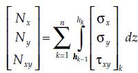
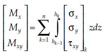
157 Macromechanical Analysis of a Laminate Integrating the global stresses in each lamina gives the resultant forces per unit length in the x y plane through the laminate thickness as 4-14 Similarly, integrating the global stresses in each lamina gives the resulting moments per unit length in the x y plane through the laminate thickness as 4-15 Islamic Azad University, Najafabad Branch 214
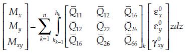
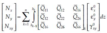
158 Macromechanical Analysis of a Laminate Which gives 4-16 (4-12) in (4-16) Islamic Azad University, Najafabad Branch 215


159 Macromechanical Analysis of a Laminate Due to independency of midplane strains and plate curvatures to z coordinate & to be constant of the transformed reduced stiffness matrix for each ply: Knowing that: Islamic Azad University, Najafabad Branch 216


160 Macromechanical Analysis of a Laminate It gives: Extensional Matrix relating the resultant in-plane forces to the in-plane strains Coupling Matrix coupling the force and moment terms to the midplane strains and midplane curvatures Bending Stiffness Matrix Bending Stiffness Matrix relating the resultant bending moments to the plate curvatures Islamic Azad University, Najafabad Branch 217
161 Macromechanical Analysis of a Laminate Combining these eqs. gives 6 simultaneous linear eqs. & six unknown as: 4-24 Islamic Azad University, Najafabad Branch 218
162 Macromechanical Analysis of a Laminate Steps for analyzing a laminated composite subjected to the applied forces and moments: 1.Find the value of the reduced stiffness matrix [Q] for each ply using its four elastic moduli, E1, E2, v12 & G12 (Eq.6-7 chap.2) 2. Find the value of the transformed reduced stiffness matrix for each ply using the [Q] matrix calculated in step 1 and the angle of the ply (Eq.7-7 Chap.2). 3. Knowing the thickness, tk, of each ply, find the coordinate of the top and bottom surface, hi, i = 1, n, of each ply, using Eqs. (4-13). 4. Use the matrices from step 2 and the location of each ply from step 3 to find the three stiffness matrices [A], [B], and [D] from Eqs. (4-23). 5. Substitute the stiffness matrix values found in step 4 and the applied forces and moments in Eq. (4-24). Islamic Azad University, Najafabad Branch 219
163 Macromechanical Analysis of a Laminate 6. Solve the six simultaneous Eqs. (4-24) to find the midplane strains and curvatures. 7. Now that the location of each ply is known, find the global strains in each ply using Eq. (4-10). 8. For finding the global stresses, use the stress strain (Eq. 7-6 chap.2). 9. For finding the local strains, use the transformation (Eq. 7-4 chap.2). 10. For finding the local stresses, use the transformation (Eq. 7-1 chap.2). Islamic Azad University, Najafabad Branch 220
164 Macromechanical Analysis of a Laminate Example 4.2: Find the three stiffness matrices [A], [B], and [D] for a threeply [0/30/ 45] graphite/epoxy laminate. Use the unidirectional properties from Table of slide 95 of graphite/epoxy. Assume that each lamina has a thickness of 5 mm. Solution: the reduced stiffness matrix for the 0 graphite/epoxy ply is: Islamic Azad University, Najafabad Branch, A. Atrian 221
165 Macromechanical Analysis of a Laminate the transformed reduced stiffness matrix 7-7 chap.2): for each of the three plies is (Eq. Islamic Azad University, Najafabad Branch 222

166 Macromechanical Analysis of a Laminate the locations of the ply surfaces are (Eq. 4-13): Islamic Azad University, Najafabad Branch 223

167 Macromechanical Analysis of a Laminate Islamic Azad University, Najafabad Branch 224

 Percentage of load, Nx, taken by each ply Solution: Macromechanical Analysis of a")
168 Example 4.3: For previous example if the laminate is subjected to a load of Nx = Ny = 1000 N/m, find: (a) Mid-plane strains and curvatures (b) Global and local stresses on top surface of 30 ply (c) Percentage of load, Nx, taken by each ply Solution: Macromechanical Analysis of a Laminate Solving this system of eqs. gives Islamic Azad University, Najafabad Branch 225


 in the 30 ply at the top surface: Islamic Azad")
169 Macromechanical Analysis of a Laminate The strains at the top surface of the 30 ply (z=h1= m) (Eq. 4-10): The global stresses from Eq. 7-6 chap.2: The local strains (Eq. 7-4 chap.2) and local stresses (Eq. 7-1 chap.2) in the 30 ply at the top surface: Islamic Azad University, Najafabad Branch 226

")

170 Macromechanical Analysis of a Laminate Global Strains (m/m) Islamic Azad University, Najafabad Branch 227
 Islamic Azad University, Najafabad Branch")
171 Global Stresses (Pa) Macromechanical Analysis of a Laminate Local Strains (m/m) Islamic Azad University, Najafabad Branch 228

172 Local Stresses (Pa) Macromechanical Analysis of a Laminate The portion of the load, Nx, taken by each ply can be calculated by integrating the stress, σxx, through the thickness of each ply. However, because the stress varies linearly through each ply, the portion of the load, Nx, taken is simply the product of the stress, σxx, at the middle of each ply and the thickness of the ply: Islamic Azad University, Najafabad Branch 229
173 Macromechanical Analysis of a Laminate The sum total of the loads shared by each ply is 1000 N/m, ( ), which is the applied load in the x-direction, Nx. Islamic Azad University, Najafabad Branch 230
![Macromechanical Analysis of a Laminate Problems of Chap.4: 1.Condense (summarize) the following expanded laminate codes: a. [0/45/ 45/90] b. [0/45/ 45/ 45/45/0] c.](/docs-images/87/96933415/images/174-0.jpg "[0/90/60/60/90/0] d. [0/45/60/45/0] e. [45/ 45/45/ 45/ 45/45/ 45/45] 2.Expand the following laminate codes: Islamic Azad University, Najafabad Branch, A.")
174 Macromechanical Analysis of a Laminate Problems of Chap.4: 1.Condense (summarize) the following expanded laminate codes: a. [0/45/ 45/90] b. [0/45/ 45/ 45/45/0] c. [0/90/60/60/90/0] d. [0/45/60/45/0] e. [45/ 45/45/ 45/ 45/45/ 45/45] 2.Expand the following laminate codes: Islamic Azad University, Najafabad Branch, A. Atrian 231
TABLE OF CONTENTS. Mechanics of Composite Materials, Second Edition Autar K Kaw University of South Florida, Tampa, USA
 Mechanics of Composite Materials, Second Edition Autar K Kaw University of South Florida, Tampa, USA TABLE OF CONTENTS 1. INTRODUCTION TO COMPOSITE MATERIALS 1.1 Introduction... 1.2 Classification... 1.2.1
Chapter 2 - Macromechanical Analysis of a Lamina. Exercise Set. 2.1 The number of independent elastic constants in three dimensions are: 2.
 Chapter - Macromechanical Analysis of a Lamina Exercise Set. The number of independent elastic constants in three dimensions are: Anisotropic Monoclinic 3 Orthotropic 9 Transversely Orthotropic 5 Isotropic.
Module III - Macro-mechanics of Lamina. Lecture 23. Macro-Mechanics of Lamina
 Module III - Macro-mechanics of Lamina Lecture 23 Macro-Mechanics of Lamina For better understanding of the macromechanics of lamina, the knowledge of the material properties in essential. Therefore, the
ME 582 Advanced Materials Science. Chapter 2 Macromechanical Analysis of a Lamina (Part 2)
") ME 582 Advanced Materials Science Chapter 2 Macromechanical Analysis of a Lamina (Part 2) Laboratory for Composite Materials Research Department of Mechanical Engineering University of South Alabama, Mobile,
ME 582 Advanced Materials Science Chapter 2 Macromechanical Analysis of a Lamina (Part 2) Laboratory for Composite Materials Research Department of Mechanical Engineering University of South Alabama, Mobile,
Mechanics of Composite Materials, Second Edition Autar K Kaw University of South Florida, Tampa, USA
 Mechanics of Composite Materials, Second Edition Autar K Kaw University of South Florida, Tampa, USA What programs are in PROMAL? Master Menu The master menu screen with five separate applications from
Lecture 8. Stress Strain in Multi-dimension
 Lecture 8. Stress Strain in Multi-dimension Module. General Field Equations General Field Equations [] Equilibrium Equations in Elastic bodies xx x y z yx zx f x 0, etc [2] Kinematics xx u x x,etc. [3]
ME 7502 Lecture 2 Effective Properties of Particulate and Unidirectional Composites
 ME 75 Lecture Effective Properties of Particulate and Unidirectional Composites Concepts from Elasticit Theor Statistical Homogeneit, Representative Volume Element, Composite Material Effective Stress-
Composite Structures. Indian Institute of Technology Kanpur
 Mechanics of Laminated Composite Structures Nachiketa Tiwari Indian Institute of Technology Kanpur Lecture 23 Analysis of an Orthotropic Ply Lecture Overview Introduction Engineering constants for an 2
QUESTION BANK Composite Materials
 QUESTION BANK Composite Materials 1. Define composite material. 2. What is the need for composite material? 3. Mention important characterits of composite material 4. Give examples for fiber material 5.
Smart Materials, Adaptive Structures, and Intelligent Mechanical Systems
 Smart Materials, Adaptive Structures, and Intelligent Mechanical Systems Bishakh Bhattacharya & Nachiketa Tiwari Indian Institute of Technology Kanpur Lecture 19 Analysis of an Orthotropic Ply References
Computational Analysis for Composites
 Computational Analysis for Composites Professor Johann Sienz and Dr. Tony Murmu Swansea University July, 011 The topics covered include: OUTLINE Overview of composites and their applications Micromechanics
MODELING OF CONCRETE MATERIALS AND STRUCTURES. Kaspar Willam
 MODELING OF CONCRETE MATERIALS AND STRUCTURES Class Meeting #1: Fundamentals Kaspar Willam University of Colorado at Boulder Notation: Direct and indicial tensor formulations Fundamentals: Stress and Strain
MECHANICS OF MATERIALS
 CHATR Stress MCHANICS OF MATRIALS and Strain Axial Loading Stress & Strain: Axial Loading Suitability of a structure or machine may depend on the deformations in the structure as well as the stresses induced
3D Elasticity Theory
 3D lasticity Theory Many structural analysis problems are analysed using the theory of elasticity in which Hooke s law is used to enforce proportionality between stress and strain at any deformation level.
Constitutive Equations
 Constitutive quations David Roylance Department of Materials Science and ngineering Massachusetts Institute of Technology Cambridge, MA 0239 October 4, 2000 Introduction The modules on kinematics (Module
Samantha Ramirez, MSE. Stress. The intensity of the internal force acting on a specific plane (area) passing through a point. F 2
 passing through a point. F 2") Samantha Ramirez, MSE Stress The intensity of the internal force acting on a specific plane (area) passing through a point. Δ ΔA Δ z Δ 1 2 ΔA Δ x Δ y ΔA is an infinitesimal size area with a uniform force
Samantha Ramirez, MSE Stress The intensity of the internal force acting on a specific plane (area) passing through a point. Δ ΔA Δ z Δ 1 2 ΔA Δ x Δ y ΔA is an infinitesimal size area with a uniform force
Enhancing Prediction Accuracy In Sift Theory
 18 TH INTERNATIONAL CONFERENCE ON COMPOSITE MATERIALS Enhancing Prediction Accuracy In Sift Theory J. Wang 1 *, W. K. Chiu 1 Defence Science and Technology Organisation, Fishermans Bend, Australia, Department
MECHANICS OF MATERIALS
 Third E CHAPTER 2 Stress MECHANICS OF MATERIALS Ferdinand P. Beer E. Russell Johnston, Jr. John T. DeWolf Lecture Notes: J. Walt Oler Texas Tech University and Strain Axial Loading Contents Stress & Strain:
DESIGN OF LAMINATES FOR IN-PLANE LOADING
 DESIGN OF LAMINATES FOR IN-PLANOADING G. VERCHERY ISMANS 44 avenue F.A. Bartholdi, 72000 Le Mans, France Georges.Verchery@m4x.org SUMMARY This work relates to the design of laminated structures primarily
9 Strength Theories of Lamina
 9 trength Theories of Lamina 9- TRENGTH O ORTHOTROPIC LAMINA or isotropic materials the simplest method to predict failure is to compare the applied stresses to the strengths or some other allowable stresses.
Pressure Vessels Stresses Under Combined Loads Yield Criteria for Ductile Materials and Fracture Criteria for Brittle Materials
 Pressure Vessels Stresses Under Combined Loads Yield Criteria for Ductile Materials and Fracture Criteria for Brittle Materials Pressure Vessels: In the previous lectures we have discussed elements subjected
[5] Stress and Strain
![[5] Stress and Strain](/thumbs/95/123344550.jpg "[5] Stress and Strain") [5] Stress and Strain Page 1 of 34 [5] Stress and Strain [5.1] Internal Stress of Solids [5.2] Design of Simple Connections (will not be covered in class) [5.3] Deformation and Strain [5.4] Hooke s Law
[5] Stress and Strain Page 1 of 34 [5] Stress and Strain [5.1] Internal Stress of Solids [5.2] Design of Simple Connections (will not be covered in class) [5.3] Deformation and Strain [5.4] Hooke s Law
2. Mechanics of Materials: Strain. 3. Hookes's Law
 Mechanics of Materials Course: WB3413, Dredging Processes 1 Fundamental Theory Required for Sand, Clay and Rock Cutting 1. Mechanics of Materials: Stress 1. Introduction 2. Plane Stress and Coordinate
Use Hooke s Law (as it applies in the uniaxial direction),
,") 0.6 STRSS-STRAIN RLATIONSHIP Use the principle of superposition Use Poisson s ratio, v lateral longitudinal Use Hooke s Law (as it applies in the uniaxial direction), x x v y z, y y vx z, z z vx y Copyright
0.6 STRSS-STRAIN RLATIONSHIP Use the principle of superposition Use Poisson s ratio, v lateral longitudinal Use Hooke s Law (as it applies in the uniaxial direction), x x v y z, y y vx z, z z vx y Copyright
LAMINATION THEORY FOR THE STRENGTH OF FIBER COMPOSITE MATERIALS
 XXII. LAMINATION THEORY FOR THE STRENGTH OF FIBER COMPOSITE MATERIALS Introduction The lamination theory for the elastic stiffness of fiber composite materials is the backbone of the entire field, it holds
Exercise: concepts from chapter 8
 Reading: Fundamentals of Structural Geology, Ch 8 1) The following exercises explore elementary concepts associated with a linear elastic material that is isotropic and homogeneous with respect to elastic
Module 7: Micromechanics Lecture 29: Background of Concentric Cylinder Assemblage Model. Introduction. The Lecture Contains
 Introduction In this lecture we are going to introduce a new micromechanics model to determine the fibrous composite effective properties in terms of properties of its individual phases. In this model
Composites Design and Analysis. Stress Strain Relationship
 Composites Design and Analysis Stress Strain Relationship Composite design and analysis Laminate Theory Manufacturing Methods Materials Composite Materials Design / Analysis Engineer Design Guidelines
UNIT I SIMPLE STRESSES AND STRAINS
 Subject with Code : SM-1(15A01303) Year & Sem: II-B.Tech & I-Sem SIDDHARTH GROUP OF INSTITUTIONS :: PUTTUR Siddharth Nagar, Narayanavanam Road 517583 QUESTION BANK (DESCRIPTIVE) UNIT I SIMPLE STRESSES
The Accuracy of Characteristic Length Method on Failure Load Prediction of Composite Pinned Joints
 , June 30 - July 2, 2010, London, U.K. The Accuracy of Characteristic Length Method on Failure Load Prediction of Composite Pinned Joints O. Aluko, and Q. Mazumder Abstract An analytical model was developed
Practice Final Examination. Please initial the statement below to show that you have read it
 EN175: Advanced Mechanics of Solids Practice Final Examination School of Engineering Brown University NAME: General Instructions No collaboration of any kind is permitted on this examination. You may use
INTERNATIONAL JOURNAL OF APPLIED ENGINEERING RESEARCH, DINDIGUL Volume 2, No 1, 2011
 Interlaminar failure analysis of FRP cross ply laminate with elliptical cutout Venkateswara Rao.S 1, Sd. Abdul Kalam 1, Srilakshmi.S 1, Bala Krishna Murthy.V 2 1 Mechanical Engineering Department, P. V.
MECHANICS OF COMPOSITE STRUCTURES
 MECHANICS OF COMPOSITE STRUCTURES LÁSZLÓ P. KOLLÁR Budapest University of Technology and Economics GEORGE S. SPRINGER Stanford University PUBLISHED BY THE PRESS SYNDICATE OF THE UNIVERSITY OF CAMBRIDGE
Materials and Structures. Indian Institute of Technology Kanpur
 Introduction to Composite Materials and Structures Nachiketa Tiwari Indian Institute of Technology Kanpur Lecture 16 Behavior of Unidirectional Composites Lecture Overview Mt Material ilaxes in unidirectional
PRELIMINARY PREDICTION OF SPECIMEN PROPERTIES CLT and 1 st order FEM analyses
 OPTIMAT BLADES Page 1 of 24 PRELIMINARY PREDICTION OF SPECIMEN PROPERTIES CLT and 1 st order FEM analyses first issue Peter Joosse CHANGE RECORD Issue/revision date pages Summary of changes draft 24-10-02
Chapter 2: Elasticity
 OHP 1 Mechanical Properties of Materials Chapter 2: lasticity Prof. Wenjea J. Tseng ( 曾文甲 ) Department of Materials ngineering National Chung Hsing University wenjea@dragon.nchu.edu.tw Reference: W.F.
Mechanical Properties of Materials
 Mechanical Properties of Materials Strains Material Model Stresses Learning objectives Understand the qualitative and quantitative description of mechanical properties of materials. Learn the logic of
Principal Stresses, Yielding Criteria, wall structures
 Principal Stresses, Yielding Criteria, St i thi Stresses in thin wall structures Introduction The most general state of stress at a point may be represented by 6 components, x, y, z τ xy, τ yz, τ zx normal
PROMAL2012 SOFTWARE PACKAGE A USER GUIDE
 PROMAL2012 SOFTWARE PACKAGE A USER GUIDE 1. This manual is only for VISTA, WINDOWS 7 and WINDOWS 8 users. The PROMAL2012 software and manual are available at http://www.eng.usf.edu/~kaw/promal2012/ 2.
Module 4: Behaviour of a Laminae-II. Learning Unit 1: M1. M4.1 Mechanics of Composites. M4.1.1 Introduction to Mechanics of Composites
 Module 4: Behaviour of a Laminae-II Learning Unit 1: M1 M4.1 Mechanics of Composites M4.1.1 Introduction to Mechanics of Composites The relation between ply uniaxial strengths and constituent properties
3D and Planar Constitutive Relations
 3D and Planar Constitutive Relations A School on Mechanics of Fibre Reinforced Polymer Composites Knowledge Incubation for TEQIP Indian Institute of Technology Kanpur PM Mohite Department of Aerospace
Failure analysis of serial pinned joints in composite materials
 Indian Journal of Engineering & Materials Sciences Vol. 18, April 2011, pp. 102-110 Failure analysis of serial pinned joints in composite materials Alaattin Aktaş* Department of Mechanical Engineering,
7.6 Stress in symmetrical elastic beam transmitting both shear force and bending moment
 7.6 Stress in symmetrical elastic beam transmitting both shear force and bending moment à It is more difficult to obtain an exact solution to this problem since the presence of the shear force means that
MECHANICS OF MATERIALS
 Third CHTR Stress MCHNICS OF MTRIS Ferdinand. Beer. Russell Johnston, Jr. John T. DeWolf ecture Notes: J. Walt Oler Texas Tech University and Strain xial oading Contents Stress & Strain: xial oading Normal
Module-6: Laminated Composites-II. Learning Unit-1: M6.1. M 6.1 Structural Mechanics of Laminates
 Module-6: Laminated Composites-II Learning Unit-1: M6.1 M 6.1 Structural Mechanics of Laminates Classical Lamination Theory: Laminate Stiffness Matrix To this point in the development of classical lamination
Prediction of Elastic Constants on 3D Four-directional Braided
 Prediction of Elastic Constants on 3D Four-directional Braided Composites Prediction of Elastic Constants on 3D Four-directional Braided Composites Liang Dao Zhou 1,2,* and Zhuo Zhuang 1 1 School of Aerospace,
NORMAL STRESS. The simplest form of stress is normal stress/direct stress, which is the stress perpendicular to the surface on which it acts.
 NORMAL STRESS The simplest form of stress is normal stress/direct stress, which is the stress perpendicular to the surface on which it acts. σ = force/area = P/A where σ = the normal stress P = the centric
N = Shear stress / Shear strain
 UNIT - I 1. What is meant by factor of safety? [A/M-15] It is the ratio between ultimate stress to the working stress. Factor of safety = Ultimate stress Permissible stress 2. Define Resilience. [A/M-15]
Influence of the filament winding process variables on the mechanical behavior of a composite pressure vessel
 Influence of the filament winding process variables on the mechanical behavior of a composite pressure vessel G. Vargas 1 & A. Miravete 2 1 Universidad Pontificia Bolivariana, Facultad de Ingeniería Mecánica,
SEMM Mechanics PhD Preliminary Exam Spring Consider a two-dimensional rigid motion, whose displacement field is given by
 SEMM Mechanics PhD Preliminary Exam Spring 2014 1. Consider a two-dimensional rigid motion, whose displacement field is given by u(x) = [cos(β)x 1 + sin(β)x 2 X 1 ]e 1 + [ sin(β)x 1 + cos(β)x 2 X 2 ]e
MECH 5312 Solid Mechanics II. Dr. Calvin M. Stewart Department of Mechanical Engineering The University of Texas at El Paso
 MECH 5312 Solid Mechanics II Dr. Calvin M. Stewart Department of Mechanical Engineering The University of Texas at El Paso Table of Contents Thermodynamics Derivation Hooke s Law: Anisotropic Elasticity
International Journal of Innovative Research in Science, Engineering and Technology Vol. 2, Issue 7, July 2013
 ANALYSIS AND MITIGATION OF STRESS CONCENTRATION FACTOR OF A RECTANGULAR ISOTROPIC AND ORTHOTROPIC PLATE WITH CENTRAL CIRCULAR HOLE SUBJECTED TO INPLANE STATIC LOADING BY DESIGN OPTIMIZATION Shubhrata Nagpal
Composite models 30 and 131: Ply types 0 and 8 calibration
 Model calibration Composite Bi-Phase models 30 and 3 for elastic, damage and failure PAM-CRASH material model 30 is for solid and 3 for multi-layered shell elements. Within these models different ply types
Micromechanical analysis of FRP hybrid composite lamina for in-plane transverse loading
 Indian Journal of Engineering & Materials Sciences Vol. 15, October 2008, pp. 382-390 Micromechanical analysis of FRP hybrid composite lamina for in-plane transverse loading K Sivaji Babu a *, K Mohana
Hygrothermal stresses in laminates
 Hygrothermal stresses in laminates Changing environment conditions (temperature and moisture) have an important effect on the properties which are matrix dominated. Change in temperaturet and moisture
Jeff Brown Hope College, Department of Engineering, 27 Graves Pl., Holland, Michigan, USA UNESCO EOLSS
 MECHANICS OF MATERIALS Jeff Brown Hope College, Department of Engineering, 27 Graves Pl., Holland, Michigan, USA Keywords: Solid mechanics, stress, strain, yield strength Contents 1. Introduction 2. Stress
DYNAMIC FAILURE ANALYSIS OF LAMINATED COMPOSITE PLATES
 Association of Metallurgical Engineers of Serbia AMES Scientific paper UDC:669.1-419:628.183=20 DYNAMIC FAILURE ANALYSIS OF LAMINATED COMPOSITE PLATES J. ESKANDARI JAM 1 and N. GARSHASBI NIA 2 1- Aerospace
2.1 Background of Piping Stresses
 2 Research Review One of the major additions to Tmin was the inclusion of analysis of a 2-Dimensional vertical piping span. The original plan from Dupont was to include several types of 2-D and 3-D vertical
Fracture Mechanics, Damage and Fatigue: Composites
 University of Liège Aerospace & Mechanical Engineering Fracture Mechanics, Damage and Fatigue: Composites Ludovic Noels Computational & Multiscale Mechanics of Materials CM3 http://www.ltas-cm3.ulg.ac.be/
EMA 3702 Mechanics & Materials Science (Mechanics of Materials) Chapter 2 Stress & Strain - Axial Loading
 Chapter 2 Stress & Strain - Axial Loading") MA 3702 Mechanics & Materials Science (Mechanics of Materials) Chapter 2 Stress & Strain - Axial Loading MA 3702 Mechanics & Materials Science Zhe Cheng (2018) 2 Stress & Strain - Axial Loading Statics
MA 3702 Mechanics & Materials Science (Mechanics of Materials) Chapter 2 Stress & Strain - Axial Loading MA 3702 Mechanics & Materials Science Zhe Cheng (2018) 2 Stress & Strain - Axial Loading Statics
Module 7: Micromechanics Lecture 34: Self Consistent, Mori -Tanaka and Halpin -Tsai Models. Introduction. The Lecture Contains. Self Consistent Method
 Introduction In this lecture we will introduce some more micromechanical methods to predict the effective properties of the composite. Here we will introduce expressions for the effective properties without
3 2 6 Solve the initial value problem u ( t) 3. a- If A has eigenvalues λ =, λ = 1 and corresponding eigenvectors 1
 3. a- If A has eigenvalues λ =, λ = 1 and corresponding eigenvectors 1") Math Problem a- If A has eigenvalues λ =, λ = 1 and corresponding eigenvectors 1 3 6 Solve the initial value problem u ( t) = Au( t) with u (0) =. 3 1 u 1 =, u 1 3 = b- True or false and why 1. if A is
Math Problem a- If A has eigenvalues λ =, λ = 1 and corresponding eigenvectors 1 3 6 Solve the initial value problem u ( t) = Au( t) with u (0) =. 3 1 u 1 =, u 1 3 = b- True or false and why 1. if A is
Mechanical and Thermal Properties of Coir Fiber Reinforced Epoxy Composites Using a Micromechanical Approach
 Mechanical and Thermal Properties of Coir Fiber Reinforced Epoxy Composites Using a Micromechanical Approach Sandhyarani Biswas Department of Mechanical Engineering, N.I.T Rourkela, INDIA Abstract: Now-a-days,
FINITE ELEMENT ANALYSIS OF COMPOSITE MATERIALS
 FINITE ELEMENT ANALYSIS OF COMPOSITE MATERIALS Ever J. Barbero Department of Mechanical and Aerospace Engineering West Virginia University USA CRC Press Taylor &.Francis Group Boca Raton London New York
Comparison of Ply-wise Stress-Strain results for graphite/epoxy laminated plate subjected to in-plane normal loads using CLT and ANSYS ACP PrepPost
 Comparison of Ply-wise Stress-Strain results for graphite/epoxy laminated plate subjected to in-plane normal loads using CLT and ANSYS ACP PrepPost 1 Mihir A. Mehta, 2 Satyen D. Ramani 1 PG Student, Department
INTRODUCTION TO STRAIN
 SIMPLE STRAIN INTRODUCTION TO STRAIN In general terms, Strain is a geometric quantity that measures the deformation of a body. There are two types of strain: normal strain: characterizes dimensional changes,
Basic Equations of Elasticity
 A Basic Equations of Elasticity A.1 STRESS The state of stress at any point in a loaded bo is defined completely in terms of the nine components of stress: σ xx,σ yy,σ zz,σ xy,σ yx,σ yz,σ zy,σ zx,andσ
Understand basic stress-strain response of engineering materials.
 Module 3 Constitutive quations Learning Objectives Understand basic stress-strain response of engineering materials. Quantify the linear elastic stress-strain response in terms of tensorial quantities
Chapter 6: Plastic Theory
 OHP Mechanical Properties of Materials Chapter 6: Plastic Theory Prof. Wenjea J. Tseng 曾文甲 Department of Materials Engineering National Chung Hsing University wenjea@dragon.nchu.edu.tw Reference: W. F.
Tuesday, February 11, Chapter 3. Load and Stress Analysis. Dr. Mohammad Suliman Abuhaiba, PE
 1 Chapter 3 Load and Stress Analysis 2 Chapter Outline Equilibrium & Free-Body Diagrams Shear Force and Bending Moments in Beams Singularity Functions Stress Cartesian Stress Components Mohr s Circle for
American Society for Testing and Materials (ASTM) Standards. Mechanical Testing of Composites and their Constituents
 Standards. Mechanical Testing of Composites and their Constituents") Mechanical Testing of Composites and their Constituents American Society for Testing and Materials (ASTM) Standards Tests done to determine intrinsic material properties such as modulus and strength for
Mechanical Testing of Composites and their Constituents American Society for Testing and Materials (ASTM) Standards Tests done to determine intrinsic material properties such as modulus and strength for
BUCKLING COEFFICIENTS FOR SIMPLY SUPPORTED, FLAT, RECTANGULAR SANDWICH PANELS UNDER BIAXIAL COMPRESSION
 U. S. FOREST SERVICE RESEARCH PAPER FPL 135 APRIL 1970 BUCKLING COEFFICIENTS FOR SIMPLY SUPPORTED, FLAT, RECTANGULAR SANDWICH PANELS UNDER BIAXIAL COMPRESSION FOREST PRODUCTS LABORATORY, FOREST SERVICE
Aerospace Structural Composites I Homework 6. Anirban Chaudhuri
 Aerospace Structural Composites I Homework 6 Anirban Chaudhuri. The unidirectional Boron/Epoxy layer of Example 6.. (using E = 4GPa, E = 8.5GPa, G = 5.59GPa, =.3, t =.5mm) is to be loaded by combined axial
Analysis of Composite Pressure Vessels
 Analysis of Composite Pressure Vessels Reza Mohammadzadeh Gheshlaghi 1 Mohammad Hassan Hojjati Hamid Reza Mohammadi Daniali 3 1 Engineering Research Centre, Tabriz, Iran,3 Department of Mechanical Engineering,
UNIT-I Introduction & Plane Stress and Plane Strain Analysis
 SIDDHARTH INSTITUTE OF ENGINEERING & TECHNOLOGY:: PUTTUR (AUTONOMOUS) Siddharth Nagar, Narayanavanam Road 517583 QUESTION BANK (DESCRIPTIVE) Subject with Code : Advanced Solid Mechanics (18CE1002) Year
TRESS - STRAIN RELATIONS
 TRESS - STRAIN RELATIONS Stress Strain Relations: Hook's law, states that within the elastic limits the stress is proportional to t is impossible to describe the entire stress strain curve with simple
Module 7: Micromechanics Lecture 25: Strength of Materials Approach. Introduction. The Lecture Contains. Effective Transverse Modulus
 Introduction In the previous lecture we have introduced the concept of Representative Volume Element or Unit Cell. This is the basic building block in a micromechanical study. Further, we explained the
Mechanical Behavior of Composite Tapered Lamina
 International Journal of Engineering Research and Development e-issn: 2278-067X, p-issn: 2278-800X, www.ijerd.com Volume 10, Issue 8 (August 2014), PP.19-27 Mechanical Behavior of Composite Tapered Lamina
STRESS, STRAIN AND DEFORMATION OF SOLIDS
 VELAMMAL COLLEGE OF ENGINEERING AND TECHNOLOGY, MADURAI 625009 DEPARTMENT OF CIVIL ENGINEERING CE8301 STRENGTH OF MATERIALS I -------------------------------------------------------------------------------------------------------------------------------
Failure from static loading
 Failure from static loading Topics Quiz /1/07 Failures from static loading Reading Chapter 5 Homework HW 3 due /1 HW 4 due /8 What is Failure? Failure any change in a machine part which makes it unable
Most of the material in this package is based on a recently published book. This is:
 Mechanics of Composite Materials Version 2.1 Bill Clyne, University of Cambridge Boban Tanovic, MATTER Assumed Pre-knowledge It is assumed that the student is familiar with simple concepts of mechanical
CONSTITUTIVE RELATIONS FOR LINEAR ELASTIC SOLIDS
 Chapter 9 CONSTITUTIV RLATIONS FOR LINAR LASTIC SOLIDS Figure 9.1: Hooke memorial window, St. Helen s, Bishopsgate, City of London 211 212 CHAPTR 9. CONSTITUTIV RLATIONS FOR LINAR LASTIC SOLIDS 9.1 Mechanical
Theory at a Glance (for IES, GATE, PSU)
") 1. Stress and Strain Theory at a Glance (for IES, GATE, PSU) 1.1 Stress () When a material is subjected to an external force, a resisting force is set up within the component. The internal resistance force
1. Stress and Strain Theory at a Glance (for IES, GATE, PSU) 1.1 Stress () When a material is subjected to an external force, a resisting force is set up within the component. The internal resistance force
MATERIAL MECHANICS, SE2126 COMPUTER LAB 4 MICRO MECHANICS. E E v E E E E E v E E + + = m f f. f f
 MATRIAL MCHANICS, S226 COMPUTR LAB 4 MICRO MCHANICS 2 2 2 f m f f m T m f m f f m v v + + = + PART A SPHRICAL PARTICL INCLUSION Consider a solid granular material, a so called particle composite, shown
LAMINATED COMPOSITE PLATES
 LAMINATED COMPOSITE PLATES David Roylance Department of Materials Science and Engineering Massachusetts Institute of Technology Cambridge, MA 02139 February 10, 2000 Introduction This document is intended
ON HOMOGENIZATION AND DE-HOMOGENIZATION OF COMPOSITE MATERIALS. A Thesis. Submitted to the Faculty. Drexel University.
 ON HOMOGENIZATION AND DE-HOMOGENIZATION OF COMPOSITE MATERIALS A Thesis Submitted to the Faculty of Drexel University by Chang (Karen) Yan in partial fulfillment of the requirements for the degree of Doctor
MINE ROOF SUPPORT DESIGN AND ANALYSIS. Document no : Revision no : 1.0
 MINE ROOF SUPPORT DESIGN AND ANALYSIS Document no : 1806-2697-23 Revision no : 1.0 DOCUMENT TITLE : MINE ROOF SUPPORT DESIGN AND ANALYSIS DOCUMENT NUMBER : 1806-2697-23 ISSUE : Issue 1.0 DATE : 7 October
Plasticity R. Chandramouli Associate Dean-Research SASTRA University, Thanjavur
 Plasticity R. Chandramouli Associate Dean-Research SASTRA University, Thanjavur-613 401 Joint Initiative of IITs and IISc Funded by MHRD Page 1 of 9 Table of Contents 1. Plasticity:... 3 1.1 Plastic Deformation,
Effect of Thermal Stresses on the Failure Criteria of Fiber Composites
 Effect of Thermal Stresses on the Failure Criteria of Fiber Composites Martin Leong * Institute of Mechanical Engineering Aalborg University, Aalborg, Denmark Bhavani V. Sankar Department of Mechanical
MICROMECHANICAL ANALYSIS OF FRP COMPOSITES SUBJECTED TO LONGITUDINAL LOADING
 MICROMECHANICAL ANALYSIS OF FRP COMPOSITES SUBJECTED TO LONGITUDINAL LOADING N. Krishna Vihari 1, P. Phani Prasanthi 1, V. Bala Krishna Murthy 2* and A. Srihari Prasad 3 1 Mech. Engg. Dept., P. V. P. Siddhartha
Development of a code to generate randomly distributed short fiber composites to estimate mechanical properties using FEM
 International Journal of Theoretical and Applied Mechanics. ISSN 0973-6085 Volume 12, Number 4 (2017) pp. 863-872 Research India Publications http://www.ripublication.com Development of a code to generate
Chapter 3. Load and Stress Analysis
 Chapter 3 Load and Stress Analysis 2 Shear Force and Bending Moments in Beams Internal shear force V & bending moment M must ensure equilibrium Fig. 3 2 Sign Conventions for Bending and Shear Fig. 3 3
2. Rigid bar ABC supports a weight of W = 50 kn. Bar ABC is pinned at A and supported at B by rod (1). What is the axial force in rod (1)?
. What is the axial force in rod (1)?") IDE 110 S08 Test 1 Name: 1. Determine the internal axial forces in segments (1), (2) and (3). (a) N 1 = kn (b) N 2 = kn (c) N 3 = kn 2. Rigid bar ABC supports a weight of W = 50 kn. Bar ABC is pinned at
IDE 110 S08 Test 1 Name: 1. Determine the internal axial forces in segments (1), (2) and (3). (a) N 1 = kn (b) N 2 = kn (c) N 3 = kn 2. Rigid bar ABC supports a weight of W = 50 kn. Bar ABC is pinned at
Learning Units of Module 3
 Module Learning Units of Module M. tress-train oncepts in Three- Dimension M. Introduction to Anisotropic lasticity M. Tensorial oncept and Indicial Notations M.4 Plane tress oncept Action of force (F)
UNIVERSITY OF SASKATCHEWAN ME MECHANICS OF MATERIALS I FINAL EXAM DECEMBER 13, 2008 Professor A. Dolovich
 UNIVERSITY OF SASKATCHEWAN ME 313.3 MECHANICS OF MATERIALS I FINAL EXAM DECEMBER 13, 2008 Professor A. Dolovich A CLOSED BOOK EXAMINATION TIME: 3 HOURS For Marker s Use Only LAST NAME (printed): FIRST
Open-hole compressive strength prediction of CFRP composite laminates
 Open-hole compressive strength prediction of CFRP composite laminates O. İnal 1, A. Ataş 2,* 1 Department of Mechanical Engineering, Balikesir University, Balikesir, 10145, Turkey, inal@balikesir.edu.tr
CHAPTER 4: BENDING OF BEAMS
 (74) CHAPTER 4: BENDING OF BEAMS This chapter will be devoted to the analysis of prismatic members subjected to equal and opposite couples M and M' acting in the same longitudinal plane. Such members are
EFFECT OF ELLIPTIC OR CIRCULAR HOLES ON THE STRESS DISTRIBUTION IN PLATES
 EFFECT OF ELLIPTIC OR CIRCULAR HOLES ON THE STRESS DISTRIBUTION IN PLATES OF WOOD OR PLYWOOD CONSIDERED AS ORTHOTROPIC MATERIALS Information Revied and Reaffirmed March 1956 No. 1510 EFFECT OF ELLIPTIC
VYSOKÁ ŠKOLA BÁŇSKÁ TECHNICKÁ UNIVERZITA OSTRAVA
 VYSOKÁ ŠKOLA BÁŇSKÁ TECHNICKÁ UNIVERZITA OSTRAVA FAKULTA METALURGIE A MATERIÁLOVÉHO INŽENÝRSTVÍ APPLIED MECHANICS Study Support Leo Václavek Ostrava 2015 Title:Applied Mechanics Code: Author: doc. Ing.
MAAE 2202 A. Come to the PASS workshop with your mock exam complete. During the workshop you can work with other students to review your work.
 It is most beneficial to you to write this mock final exam UNDER EXAM CONDITIONS. This means: Complete the exam in 3 hours. Work on your own. Keep your textbook closed. Attempt every question. After the