CE 442 GEOTECHNICAL ENGINEERING SESSIONAL II
|
|
|
- Cathleen Stevens
- 5 years ago
- Views:
Transcription


1 CE 442 GEOTECHNICAL ENGINEERING SESSIONAL II Department of Civil Engineering Ahsanullah University of Science and Technology December, 2017
2 Preface The substructure or foundation is the part of a structure that is usually placed below the surface of the ground to transmit the load from the superstructure to the underlying soil or rock. It is a very important part of all the structures. Someone has been differentiated between substructure and foundation. They define the substructure as the structure which is below ground level and consists of a basement as well as foundation. This lab manual explains how load is transferred from superstructure to foundation, what should be the capacity of the sub-soil to bear the load for different types of foundations, different types of settlements as well as differential settlement and their calculations and how to design different foundations with reinforcement design. A typical building plan and a soil test report are supplied for each group of students. A plan and a soil report are also shown at the end of the manual as an exercise. This Lab manual was prepared with the help of some geotechnical engineering books and some other lecture notes. The lab manual was first prepared in The pile portion was slightly added in 2014 by Mr. Mudasser Siraj Rafi, Ex. Lecturer of Dept. of CE. In 2017 the pile portion was fully modified and the settlement of Mat foundation was prepared and added to the manual by Mr. Sabuj Chowdhury, Lecturer of Dept. of CE. The manual was checked by Prof. Dr. Md. Abul Bashar in December Ms. Tanzila Tabassum, Lecturer of Dept. of CE made the corrections according to suggestion of Prof. Dr. Md. Abul Bashar. A S M Fahad Hossain Department of Civil Engineering Ahsanullah University of Science and Technology
3 INDEX SL No. Topics Page no. 1 Chapter 1: Building Foundation 4 2 Chapter 2: Calculation of Superimposed Load 10 3 Chapter 3: Bearing Capacity of Shallow Foundation 15 4 Chapter 4: Bearing capacity of Pile Foundation 34 5 Chapter 5: Bearing capacity of Mat foundation 45 6 Chapter 6: Soil Settlement 48 Shallow Foundation Pile Foundation Mat Foundation 7 Chapter 7: Structural Design 72 Isolated Column Footing Combined and Strip Footing Mat Foundation 8 Appendix 87 Appendix-1: Work To Do Appendix-2: Soil Test Reports Appendix-3: Geo-Properties and Correlations Appendix-4: Lab report format Appendix-5: Lab Instructions 3 P a g e

4 CHAPTER 1 BUILDING FOUNDATION 4 P a g e

5 Definition The substructure or foundation is the part of a structure that is usually placed below the surface of the ground to transmit the load from the superstructure to the underlying soil or rock. There is a difference between foundation and footing. In simple words, foundation means legs and footing means the foot of the leg. In addition, foundation also serves some other functions, such as: Prevent settlement (including differential settlement) of a structure. Prevent possible movement of structure due to periodic shrinkage and swelling of subsoil. Allow building over water or water-logged ground. Resist uplifting or overturning forces due to wind. Resist lateral forces due to soil movement. Underpin (support) existing or unstable structures. Factors to be Considered in Selecting Foundation Type Subsurface conditions Groundwater conditions Column loads and spacing, basements Site constraints noise vibrations proximity to existing improvements, slope, channel Economics Figure 1.1: Loading condition of foundation (pressure distribution in different soil)
 Shallow footing (b) When B < D f < 15B Deep footing The combined name of (a) and (b) is called Shallow foundations Deep Foundation (c) When D f 15B Deep foundations")
6 General Foundation Types Types of Foundations: Foundations can be broadly classified into two types: (i) Shallow foundations (ii) Deep foundations Shallow Foundation: (a) When depth of foundation, D f B (B = width of foundation) Shallow footing (b) When B < D f < 15B Deep footing The combined name of (a) and (b) is called Shallow foundations Deep Foundation (c) When D f 15B Deep foundations Types of Shallow Footings/Foundations: From the point of view of design, shallow footings/foundations are classified into following types: 1. Spread or Isolated or Individual column footing (i) Square or Rectangular footing of uniform thickness (ii) Sloped square/rectangular footing (iii) Stepped/Pedestal square/rectangular footing 2. Combined footing (rectangular/trapezoidal as well as slab type / slab-beam type) 3. Strip or Continuous footing (wall footing) 4. Strap or Cantilever footing 5. Mat or Raft foundation Types of Deep Foundations: 1. Pile foundations 2. Pier foundations 3. Well foundations 4. Caissons, etc. Someone has been mentioned that if depth of foundation is more than about 3m, then the foundation is termed as deep foundation. 6 P a g e


7 Figure 1.2: Shallow and Deep Foundation 7 P a g e


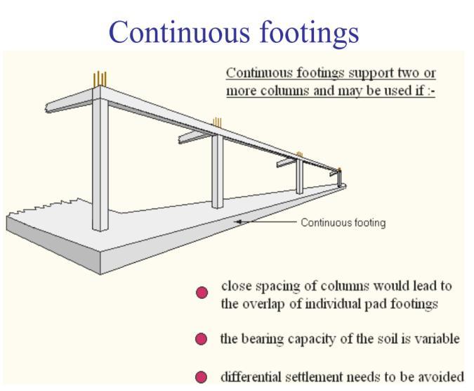
8 Figure 1.3: Shallow Foundation/Footing This type of foundation usually refers to those being rested on stratum with adequate bearing capacity and laid less than 3m below ground level. Common examples include pad, strip or raft foundations. The selection of the appropriate type of shallow foundations normally depends on the magnitude and disposition of the structural loads and the bearing capacity of subsoil. A combination of two or three types of shallow foundation in one single structure is not uncommon. Raft Foundation Raft foundation is mainly a large slab type or slab-beam type, designed to seat and support the whole or a large part of a structure. A raft is usually used when subsoil is weak, or columns are closely located and with variable loadings. It also serves as a transfer slab to combine and tie up all the vertical loading elements to the slab type foundation. By doing so, differential settlement can be avoided. 8 P a g e

 In-situ")

9 Figure 1.4: Deep Foundation Pile Foundation Pile foundation is a form of foundation using piles to transfer the loads of a superstructure down to a firm soil stratum with sufficient load bearing capacity. Materials for the piles can be of: Timber precast concrete (sometimes also prestressed) In-situ reinforced concrete steel piles in H or circular section Load from a superstructure is transmitted to the subsoil either by end bearing or skin friction or both that depends on soil conditions. End Bearing or Point Bearing Piles: When piles are driven on, or into, a hard strata or soft rock of 9 P a g e


10 adequate bearing capacity through soft stratum to transfer superimposed load, then the piles are known as end bearing or point bearing piles. Here pile tip is well seated on the rock or hard stratum. Skin friction Piles: A skin friction pile in clay is supported by adhesion between the pile and the soil or load is supported by the frictional resistance so created between the contact surface of the pile and the embracing soil. Figure 1.5: Loading condition of foundation (pressure bulb) 10 P a g e

11 CHAPTER 2 CALCULATION OF SUPERIMPOSED LOAD 11 P a g e
12 Steps to calculate the load on slab, beam, column and foundation: 1. First consider the thickness of slab from the suitable approximate formula for one-way slab or two-way slab. 2. Then determine the total load on slab per unit area considering live load, floor finish load, partition wall load in addition to self weight of slab. 3. Distribute the slab load on four adjacent beam of the slab and to find out the total load on each beam, add the load from slab on each side of beam in addition to partition wall on the beam and extra self weight of beam (i.e., load for the depth of beam which is total depth of beam minus slab thickness). 4. Each beam transfers its load to the connecting columns. Determine the total superimposed load on each column from the load of connecting beams with it in addition to self weight of column. 5. Now the column will transfer the superimposed load to foundation and then the foundation will transfer the total load to the soil including self weight of foundation. 6. We have to know the bearing capacity of underlying soil of the foundation from soil test report or from plate load test or pile load test which is suitable for the proposed structure. 7. Then area of the foundation is determined from dividing the total superimposed load on the column in addition to self weight of the footing/foundation by allowable bearing capacity of underlying soil. Initially self weight of the foundation may be assumed as about 8 to 10% of the superimposed load. 8. To calculate area of the footing unfactored load is under consideration. If wind load or earthquake load is considered then allowable bearing capacity of soil is increased by 33% to calculate the required area of the footing. Discussion on the calculation of load on beam from rectangular or square slab: The load from slab panel will be transferred to the beam in two ways: (a) For the rectangular slab it will be transferred by two triangular and two trapezoidal panels. For the square slab panel it will transfer loads by four triangular panels. This system is called yield line analysis. The panels are shown in figure below. The yield line will spread at 45 degree from each column. The distribution of slab load on short span, S and long span, L can also be determined by using the following formulae: (b) According to ACI Code: Load transferred on the short span (length = S) from slab, W S = ws 2 /4 (i) Load transferred on the long span (length = L) from slab, W L = ws 2 /4 2 m.(ii) m where, w = total load for the slab per sft. and m = S L Here, for simply supported slab, S = c/c distance between supports or clear distance + 2t (t = slab thickness), whichever is the smaller. For continuous slab, S = c/c distance should be used. Considering the rule (a) the following plan includes slab-beam with load distribution lines:
13 Problem 2.1: There is a column-beam layout plan for a 6 storied residential building given below. Calculate the superimposed load of each column. Use: Slab thickness : 6 All Beams : 12 X 18 All Columns : 12 X 12 Floor Finish (FF) : 25psf Partition Wall (PW) : 40psf Live load (LL) : 60psf Factor, a (ft) : Roll x P a g e
14 Solution: Step 1: Calculation of self weight of members Self weight of Slab (Th. 6 ) = 6 x150 = 75psf Self weight of Beam (12ʺx18ʺ) = Self weight of Column (12ʺx12ʺ) = x x x 150 = 150 plf x 150 = 150 plf Step 2: Load on Slab: UDL, w for Slab = Slab wt. of slab + Floor finish + Partition wall + Live Load = = 200psf Slab load on triangular panel: Panel No. S1/S2, etc Base (b) Height (h) Area = 0.5x bh Total load = w x 0.5bh Slab load on trapezoidal panel: Panel No. S1/S2, etc Short length, b 1 Long Length, c 1 Height, h Area = (b 1 +c 1 )/2 x h Total load = area x w Short and long lengths are the parallel sides of trapezoidal. Step 3: Load on beam: Beam No. Length L Self weight = L x weight per ft beam Load contributing Slab panel Load from slab Load from Over headed water tank Load from Stair Total load B1/ B2, etc 14 P a g e
15 Step 4: Load on column: Column No. C1/C2, etc Load from column connecting beams Load from beam (half load) Self weight of column = 150 x storey height Total load for each story Total Load for each storey x No. of storey * All Tables should be completed using Excel. 15 P a g e
16 CHAPTER 3 BEARING CAPACITY OF SHALLOW FOOTING 16 P a g e
17 All civil engineering structures impose a loading on the underlying soil (or rock). The lowest part of the structure, usually lying below the ground level, which transmits the load to the supporting soil/rock strata, is known as foundation. The ability of the underlying soil to bear the load of the foundation without overstressing the soil in terms of either shear failure or excessive settlement failure is termed as bearing capacity of soil. This is often termed as bearing capacity of foundation. The bearing capacity of a soil depends mainly on the types of foundation encountered by the soil. Foundations of structures are basically of two types; shallow and deep. The classification indicates the depth of foundation installation and the depth of the soil strata providing most of the support. A number of definitions are relevant in the context of types of foundation and bearing capacity. Basic Definitions Shallow Foundation: Shallow foundation is one that is placed on a firm soil at shallow depth below ground level and beneath the lowest part of the superstructure. e.g. spread footing or simply footing, mat or raft etc. The most useful definition of a shallow foundation refers to the founding depth being less than the breadth of the foundation. However, for wide foundation this is not acceptable. It is sensible to limit the term shallow to mean less than 3 m or less than the breadth of the foundation footing. Deep Foundation: Deep foundation is one that transmits the load of the structure considerably at a greater depth below the lowest part of the superstructure. e.g. pile, pier, caissons etc. Foundation Soil or Bed: The soil to which loads are transmitted from the base of the structure. Footing: An enlarged base of the structure to distribute the column or wall load to ground at a compatible strength and deformation characteristics of foundation soil. Mat or Raft: This is characterized by the feature of framing columns or walls into the footing in two directions. Any number of columns can be accommodated with as low as four columns. Bearing Capacity: This is a general term used to describe, the load carrying capacity of a foundation soil that enables to bear and transmit loads from a structure. Ultimate Bearing Capacity: Maximum pressure that a foundation soil can withstand without the occurrence of shear failure of the foundation. Gross Bearing Capacity: The bearing capacity inclusive of the pressure exerted by the weight of the soil standing on the foundation (called the surcharge pressure) is known as gross bearing capacity. Net bearing capacity: Gross bearing capacity minus the original overburden pressure or surcharge pressure at the foundation level; obviously, this will be the same as the gross capacity when the depth of foundation is zero. Safe bearing capacity: Net ultimate bearing capacity divided by a factor of safety. The factor of safety in foundation may range from 2 to 4, depending upon the importance of structure, and the soil profile at the site. The factor of safety should be applied to the net ultimate bearing capacity, and the surcharge pressure should then be added to get the safe bearing capacity. It is thus the maximum intensity of loading that can be transmitted to the soil without the risk of shear failure, irrespective of the settlement that may occur. Allowable bearing capacity/pressure: The maximum allowable net loading intensity on the soil at which the soil neither fails in shear nor undergoes excessive or intolerable settlement detrimental to 17 P a g e
18 the structure. The conventional design of a foundation is based on the concept of bearing capacity or allowable bearing pressure. Criteria for the Determination of Bearing Capacity The criteria for the determination of bearing capacity of a foundation are based on the requirements for the stability of the foundation. These are stated as follows: Shear failure of a foundation soil or bearing capacity failure: This is associated with plastic flow of the soil material beneath the foundation, and lateral expulsion of the soil from underneath the footing. The probable settlements, differential as well as total: The settlement of the foundation must be limited to safe, tolerable and acceptable magnitude. Factors Affecting Bearing Capacity Bearing capacity is governed by a number of factors. The following are the some of the important factors that affect the bearing capacity. Nature of soil and its physical and engineering properties Nature of the foundation and other details such as the size, shape, depth at which the foundation is located and rigidity of the structure Total and differential settlement that the structure can withstand without functional failure Location of ground water table relative to the level of foundation Initial stresses, if any. In view of the wide variety of factors that affect the bearing capacity, a systematic study of the factors involved is necessary for proper understanding. Bearing Capacity of Shallow Foundations The following methods are available for the determination of bearing capacity of a shallow foundation: Bearing capacity tables in various building codes Analytical methods Plate bearing tests Penetration tests Model tests and prototype tests Laboratory tests Bearing capacity tables have been evolved by certain agencies and incorporated in building codes. They are mostly based on past experience and some investigations. Various analytical approaches are available. Usually they are expressed in terms of equations commonly known as bearing capacity equation. The prominent of these are given by: Rankine (1857) Pauker (1889) Bell (1915) Prandlt (1921) Schleicher (1926) Fellinius (1939) Terzaghi (1943) Meyerhof (1951) Skempton (1951) Hansen (1961) Balla (1962) Vesic (1975) 18 P a g e

19 Plate bearing tests are load tests conducted in the field on a plate at shallow depth. These involve effort and expense. There are some limitations also and these are mentioned in every book. Penetration test is conducted with device known as penetrometer which measure the resistance of soil to penetration. This is correlated to bearing capacity. Model and Prototype tests are very cumbersome and costly, and are not usually practicable. Laboratory tests are simple, may be useful in arriving bearing capacity especially of pure clays. Analytical Method: Bearing Capacity Equations The following analytical approaches are available. The theory of elasticity: Schleicher s method The classical earth pressure theory: Rankine, Pauker, Bell The theory of Plasticity: Fellinius, Prandlt, Terzaghi, Meyerhof, Skempton, Hansen, Balla, Vesic Terzaghi s Theory Terzaghi (1948) developed a bearing capacity theory, assuming a failure surface consisting of three wedges (I, II and III) as illustrated in Fig.31 He considers a strip footing with rough base placed at a depth D f on a homogeneous and isotropic soil mass. In the analysis the shearing resistance of the soil above the base (AA and BB in Fig. 1) of the footing is neglected, but the effect of soil weight above the base is considered by superimposing an equivalent surcharge of intensity q= D f. The development of the failure surface in the soil is governed by the general shear failure. The soil immediately beneath the foundation forms a wedge (zone I) which moves downwards. The movement of wedge forces the soil aside and produces two zones of shear (zone II and zone III), consisting of a radial shear zone (zone II) and a linear shear zone (zone III). Zone I is considered to be at Rankine active state, zone II under radial shear and zone III at Rankine passive state. On the verge of failure, V = 0, thus q ult B = 2 P p + 2 BC. c sin (3.1) Substituting BC = B/2. cos, (3.2) q ult B = 2 P p + BC. tan ( 3.3)
20 Figure 3.1: (a) failure mechanism; (b) forces on the elastic wedge (Terzaghi s bearing capacity theory) The value of P p has been represented as the vector sum of three components, (i) cohesion, (ii) surcharge and (iii) weight of the soil. Terzaghi assumed the method of superposition to be valid presented the unit ultimate bearing capacity in the form q ult = cn c + ½ B N + qn q (3.4) Where, N c, N and N q are nondimensional bearing capacity factors and functions only of the angle of internal friction,. N q exp 2 cos 3 2.tan (3.5) N c = cot (N q 1) (3.6) K 1 p 2.tan 1 cos N 2 A close approximation of K p is given by K p 3tan (3.7) (3.8) Terzaghi s bearing capacity factors are shown in Fig. 2 These bearing capacity factors are valid for strip footing only and require to be adjusted for rectangular and circular footings as follows. It is understood that square footing is a special case of rectangular footing where length of the footing, L equals to its width B. Rectangular Footing: N c-rect = N c-strip (1 +0.3B/L) (3.9) N -rect = N -strip (1-0.2B/L) (3.10) N q-rect = N q-strip (3.11) Square Footing: Circular Footing: 20 P a g e
21 N c-square = 1.3 N c-strip N -square = 0.8 N -strip N q-square = N q-strip N c-circle = 1.3 N c-strip N -circle = 0.6 N -strip N q-circle = N q-strip As such, the following bearing capacity equations are used to estimate the ultimate bearing capacity of soil. Strip footing: q ult = cn c + ½B N + qn q (3.12) Square footing: q ult = 1.3cN c B N + qn q (3.13) Circular Footing: q ult = 1.3cN c B N + qn q (3.14) Recent research works reveal that the values of N c, N q and N given by Terzaghi are conservative and the following formulas may be used for the computation of bearing capacity factors. 45. e tan N q Nc N q 1 cot (3.16) N 1.5 N q 1 tan (3.17) 2 tan 2 (3.15) Figure 3.2: Terzaghi s bearing capacity factors 21 P a g e
22 . Figure 3.3: Terzaghi s general bearing capacity factors against SPT values for cohsionless soils Peak, Hanson and Thornburn proposed a chart for practical use where bearing capacity factors can be obtained against SPT values for cohesionless soil. The SPT values are however to be corrected for overburden and water table. The chart is presented in Fig Problem 3.1: Determine the ultimate net bearing capacity of a 2.5 m circular footing resting at a depth of 1.5 m below ground level. The water table is at great depth. The foundation soil is pure clay with the following properties: c u =50 kpa, =0, γ=16 kn/m 3, N c =5.7, N q =1, N γ =0. Also calculate the ultimate net bearing capacity, if the ground water table is at ground level. Solve the problem assuming 2.5 m square footing. Meyerhof s Theory Meyerhof (1951) considered the effects of shearing resistance within the soil above foundation level, the shape and roughness of foundation, and derived a general bearing capacity equation. According to Meyerhof, For vertical Load: q ult = cn c S c d c + ½ B N S d + qn q S q d q (3.18) For inclined load: q ult = cn c S c d c i c + ½ B N S d i + qn q S q d q i q (3.19) Where, N q = exp tan tan 2 ( /4 + /2) (3.20) N c = (N q 1)cot (3.21) N = (N q 1).tan(1.4 ) (3.22) S, d and i s are known as shape, depth and load inclination factors respectively to be used along with the bearing capacity factors N c, N and N q as indicated by their subscript. The bearing capacity factors N c, N and N q as obtained by Meyerhof s theory are presented in Fig The other associated factors are given in Table 3.2. Meyerhof also suggested considering the reduced footing dimensions to account for load eccentricity in calculating ultimate bearing capacity. Accordingly, modified length, L and width, B of the footing are given by 22 P a g e
23 L = L 2e x ; and B = B 2e y (3.23) Where, e x and e y represents the load eccentricity in longer (along the length L) and shorter (along the width B) directions respectively. He also suggested the use of plain strain in the bearing capacity equations. The triaxial should be adjusted to obtain plain strain using the formula: ps = ( B/L) triaxial Figure 3.4: Meyerhof s bearing capacity factors Table 3.1: Meyerhof s factors for shape, depth and load inclination (after Cernica, 1995) Friction, angle Shape factors Depth factors Inclination factors Any S c = K P B/L d c =1+0.2 K P.D/B i c = i q =(1- /90 o ) 2 For = 0 o S = S q = 1.0 d = d q =1.0 i =1.0 For 10 o S = S q = K P B/L d = d q =1+0.1 K P.D/B i q =(1- / ) K P = tan 2 (45 o + /2) = angle of resultant measured from vertical axis. V Q H CL e Q B B or L ` Skempton s Bearing Capacity Equation for Clay Soil Skempton (1951) proposed equations for bearing capacity of footings founded on purely cohesive soils based on extensive investigations. According to him the bearing capacity factor N c is a function of the depth of foundation and also of its shape. The equation for net ultimate bearing capacity, q net-ult is as follows: q net-ult = cn c (3.24) 23 P a g e
24 The bearing capacity factor, N c is given by: For strip footing: N c = 5( D f /B) (3.25) With a limiting value of N c of 7.5 for D f /B greater than 2.5. For square and circular footings: N c = 6( D f / B) (3.26) With a limiting value of N c of 9.0 for D f /B greater than 2.5 B is the width of strip, side of square or diameter of a circular footing. For rectangular footings: N c = 5( B/L) ( D f /B) for D f / B 2.5 (3.27) And N c = 7.5( B/L) for D f /B 2.5. (3.28) Where, B and L are breadth and length respectively, of the rectangular footing. Skempton s bearing capacity factor N c for different shapes and depths of foundation can be obtained directly from Figure Table 3.2: Comparative statement of bearing capacity factors 24 P a g e
25 Figure 3.5: Skempton s bearing capacity factors for clay soils Effect of Water Table on Bearing Capacity The general bearing capacity equation is based on the assumption that the water table is located well below the foundation level. The equation contains unit weight,, cohesion, c and the bearing capacity factors, N c, N and N q that depend on the value of. As such, some modifications are necessary in the formulation to account for the effect of water table. In the general equation there are two terms which are affected by water table movement, (i) the soil weight component that is, ½B..N ; and (ii) the surcharge component, D f.n q. Let us consider three locations of water table, as illustrated in Figur Q ult = q ult A Q ult = q ult A Q ult = q ult A D f D w B D f D w (D f + B) D w > (D f + B) (a) Case I (b) Case II (c) Case III Figure 3.6: Effect of water table and correction factors 25 P a g e
26 Case I: When the water table is well below the foundation, that is D w > (D f + B). For this case no correction is needed for both the components. Case II: When the water table is anywhere from the base of the footing to a level of well below the foundation, that is D f D w (D f + B). In this case, only the weight component is affected; whereas surcharge component remains unaffected. The aspect can be considered by substituting an equivalent unit weight e in place of. That is, e = d w + (B d w ) / B (3.29) or, e = + d w / B.( - ) = + ( Dw Df ) ( ) (3.30) B Case III. When the water table is anywhere between the ground surface and the base of the footing, that is 0 d w D f. D w D f In this case both the components are affected. For the surcharge component, the equivalent surcharge is q = D w + (D f D w ) (3.31) For the soil weight component, the required substitution in the formula is in place of in the term ½ B N. Teng(1962) suggested water table correction factors, as the unit weight of soil as 50% of its bulk unit weight. Considering case III, when the water table is at the ground surface, d w /D f = 0 and =. While water table is at the base of the footing d w /D f = 1 and = sat. This suggests a correction factor to have a value of 0.5 at d w /D f = 0 and 1.0 at d w /D f = 1. The general expression assuming linear variation is R w = ½(1 + d w /D f ). Considering case II, for d w /B = 0, the correction factor is 0.5 when water table is at the base ; for d w /B = 1, the correction factor should be 1.0. The general expression is for correction factor is R w = ½(1 + d w /B). Hence, the bearing capacity formula takes the form Q = cn c + ½ R w.b..n +R w.q.n q (3.32) Case I requires no correction for water table. Effect of Layering of Soil When footing rests on a multilayer deposit, Bowles recommends that the ultimate bearing capacity of the footing be determined using average values of cohesion, c av and the angle of internal friction av. The average values are computed over a depth H below the base of the footing, where: H n hi 0.5B tan 45 i 1 2 (3.33) c av and av are given by hi c i hi c av (3.34) h i tan i tan av (3.35) h i 26 P a g e
27 If necessary any value of h i may be multiplied by a suitable weighing factor. Average parameters should be determined, Fig. 3.16, by trial and error, since the term H used in the equation itself dependent on av. c 1, 1 h 1 H c 2, 2 h 2 c n, n h n Figure 3.7: Bearing capacity of multilayered soil system Corrections for Different Modes of Failure There are mainly three principal modes of shear failure namely general shear, local shear and punching shear. They are illustrated in Fig General Shear Failure: This occurs when a clearly defined plastic yield slip surface forms under the footing and develops outward towards one or sides and eventually to the ground surface. Failure is sudden and will often be accompanied by severe tilting leading to final collapse on one side. This mode of failure is associated with dense and overconsolidated soils of low compressibility. Local Shear Failure: In compressible soils, significant vertical movement may take place before any noticeable development of shear planes occurs. As the soil beneath the footing reaches the yield condition shear planes develop, but fail to extend to the ground surface. Some adjacent bulging may occur, but very little tilting takes place. The settlement, which occurs, will usually be the principal design criteria. Punching Shear Failure: In weak compressible soils, considerable vertical movement may take place with the development of slip surface restricted to vertical planes adjacent to the sides of the footing. Bulging at the surface is usually absent and may even be replaced by drag down. 27 P a g e
28 Figure 3.8: Modes of failure of foundation soil; (a) General shear; (b) Local shear; (c) Punching shear Correction Factors Terzaghi developed his bearing capacity equations assuming a general shear failure. For failures other than general shear he proposed reduced values of c and as: c = 0.67c ; = tan -1 (0.67tan ) (3.36) The ultimate bearing capacity is to be determined using the corrected values of c and. Vesic (1975) suggests the following modification of in case of sandy soil. * = tan -1 ( I D 0.75I D 2 )tan, for 0 I D 0.67 (3.37) * =, for I D 0.67 (3.38) Allowable Bearing Capacity Allowable bearing capacity is the minimum of the safe net bearing capacity (determined from considerations of shear failure) and safe bearing pressure (determined from considerations of permissible settlement). When wind and seismic forces are considered in design the allowable bearing capacity is suitably designed accordingly. 28 P a g e
29 Safe net bearing capacity is the maximum net intensity of loading that the foundation will safely carry without the risk of shear failure of soil irrespective of any amount of settlement that may occur. It is obtained by dividing the ultimate net bearing capacity by a suitable factor of safety. q safe-net = q ult-net / FS (3.39) Ultimate net bearing capacity is the net intensity of loading at the base of the foundation which would cause shear failure of soil. This is obtained as the difference of ultimate bearing capacity (q ult ) and the effective surcharge intensity (q) at the base level of foundations. q ult- net = q ult q (3.40) Hence, the equation for ultimate net bearing capacity for a strip footing considering general shear will take the form q ult- net = cn c + ½ B N + q(nq 1) (3.41) Safe bearing pressure (q safe-pr ) is the maximum net intensity of loading that can be imposed on the soil by the foundation without the settlement exceeding the permissible value to be determined for each type of structure and type of soil. Allowable Bearing Capacity for Sandy Soil For sandy soil safe bearing pressure is usually determined from its empirical correlations with SPT value as suggested by Terzaghi and Peck, shown in Fig It gives the bearing pressure for permissible settlement of 25 mm. For any other value of permissible settlement the safe bearing pressure can be linearly extrapolated. For any value of permissible settlement, S p, the safe bearing pressure if given by q safe-pr, Sp = (q safe-pr/25). S p.c w.c D (3.42) Average value of measured N should be within a zone of 2B below the base of the footing. C w and C D are the correction factors of N for water table and overburden respectively. Figure 3.9: Correlation between q safe-net and N value 29 P a g e
30 Allowable Bearing Capacity for Clayey Soil Allowable bearing capacity is estimated comparing the safe bearing pressure against settlement and safe bearing capacity against shear failure of foundation soil. Safe bearing pressure for clay soil is estimated considering settlement of foundation soil due to load. The total amount of settlement includes elastic, consolidation and secondary compressions. Safe net bearing capacity of clay soil is usually determined using Skemton s formula for ultimate bearing capacity and a suitable factor of safety. For a continuous footing in clay ultimate net bearing capacity can be expressed in terms of unconfined compressive strength, q u and is given by: q ult-net = cn c = 2.85 q u (3.43) Using a factor of safety of 3, for a strip footing, we get the relationship: q FS 2.85q 3 ult net u q u q u (3.44) Thus gross safe bearing capacity is: qult net qsafe gross D f q FS u D f (3.45) Peak, Hansen and Thornburn proposed a set of curves for the safe bearing capacity as shown in Fig Unlike that of sandy soil allowable bearing capacity is usually governed by the safe bearing capacity rather than the safe bearing pressure. As such Fig may be used as a design chart for clayey soils. Selection of Factor of Safety The factor of safety used in shallow foundation design depends on factors like design maximum load that coming on the foundation, shapes of foundation and the extent of subsoil investigation carried at the site. (a) (b) (c) For structures where maximum loads are likely to occur often like railway bridges, water tanks etc., the factor of safety (FS) should be 3 to 4. Where the maximum loads occur occasionally as in highway bridges, FS should be 2.5 to 3.5. When maximum loads are not likely to occur as in residential buildings, the factor of safety should be 2.0 to P a g e
31 Figure 3.10: Safe bearing capacity of footing in clay Where extensive soil investigation has been done the lower value of the range is suggested; in case of limited subsoil investigation the higher ranges of factor of safety has been recommended. Bowles suggested to following factor of safety for the types of foundation. Spread Footing: 2 to 3 Mat Foundation: 1.7 to 2.5 Footing Subjected to Uplift Forces: 1.7 to 2.5 Problem 3.2: Determine ultimate and allowable bearing capacities of the footing using Terzaghi and Meyerhof s equations. Q ult = 18.2 kn/m 3 c = 16 kn/m 2 = 24 o General Shear; Normal subsoil investigation Water table = 0.5m below ground surface Footing is 1 m x 2 m 1m From the previous problem, using the column load and the soil test report of the site given below, calculate the bearing capacity and footing size. 31 P a g e
32 Bearing Capacity is a general term used to describe, the load carrying capacity of a foundation soil that enables to bear and transmit loads from a structure. * Using Terzaghi sequation: This equation can be used both for cohesionless and cohesive soil. The common equation is- q ult = cn c + ½ B N + qn q Where, N c, N and N q are nondimensional bearing capacity factors and functions only of the angle of internal friction,. Strip footing: Square footing: Circular Footing: q ult = cn c + ½B N + qn q q ult = 1.3cN c B N + qn q q ult = 1.3cN c B N + qn q 2 N tan 2 N N q c 45.e tan N q 1 cot 1.5 N 1 tan q Figure 3.11: Terzaghi s general bearing capacity Factors against SPT values for cohsionless soils Figure 3.12: Terzaghi s bearing capacity factors 32 P a g e
33 Calculation of bearing capacity Column B (Let) Depth of foundation D f Cohesion C = q u 2 (q u =unconfined compressive Angel of internal friction. Bearing Capacity factors N c N q N Ultimate bearing capacity q ult Allowable bearing capacity q all = q ult F.S. strength) Calculation of footing size Column Column load Allowable bearing capacity q all Footing Area = Load q all. B = area (for square footing) B (rounded) Check B ok/ not * If the calculated B is less than the B that you let, then it is ok but not economical. The calculated B should be a nearest value of the B that you let but should not exceed the value. * Using Skempton s Bearing Capacity Equation for Clay Soil Skempton (1951) proposed equations for bearing capacity of footings founded on purely cohesive soils based on extensive investigations The bearing capacity factor, N c is given by For strip footing: N c = 5( D f /B) For square and circular footings: N c = 6( D f / B) For rectangular footings: q ult = cn c N c = 5( B/L) ( D f /B) for D f / B 2.5 And N c = 7.5( B/L) for D f /B 2.5. Or from the graph Figure 3.13: Skempton s bearing capacity factors for clay soils 33 P a g e
34 Calculation of bearing capacity Column Depth of foundation D f Cohesion C = q u 2 (q u =unconfined compressive Bearing Capacity factor N c Ultimate bearing capacity q ult Allowable bearing capacity q all = q ult F.S. strength) Calculation of footing size Column Column load Allowable bearing capacity q all Footing Area = Load q all. B = area (for square footing) B (rounded) Check B ok/ not * If the calculated B is less than the B that you let, then it is ok but not economical. The calculated B should be a nearest value of the B that you let but should not exceed the value. 34 P a g e

35 CHAPTER 4 BEARING CAPACITY OF PILE FOUNDATION 35 P a g e

36 Pile Capacity A spacing of three times the diameter of the piles is commonly selected as the trial spacing and checked against the criterion that the sun of the shearing and bearing capacities of the group of piles must be at least equal to the capacity of a single pile multiplied by the number of piles in the group, which termed as Individual Action of Pile Cap. In Group Action of Pile Cap, the pile group is considered as a single pile and capacity is determined. But 2/3 of the total capacity is considered effective to carry the total load. Therefore, Individual action of Pile Cap = Individual capacity of a pile x number of pile in the pile group 36 P a g e
37 Group action of Pile Cap = 2 x Capacity of group pile 3 Pile Foundation Type Pile Foundation Design Figure 4.1: Individual and Group Action Capacity 37 P a g e


38 Pile, Pile Cap & Column Position Figure 4.2: Pile, Pile Cap & Column Position Pile Spacing Figure 4.3: Pile Spacing 38 P a g e

39 Bored Pile In Clay Figure 4.4: Bored Pile in Clay 39 P a g e
40 The ultimate bearing capacity of a pile is considered to be the sum of end bearing resistance and the resistance due to skin friction where, Q up = Q eb + Q sf (4.1) Q up = Ultimate bearing load of the pile Q eb = End bearing resistance of the pile Q sf = Skin friction resistance of the pile Q eb = A p q p (4.2) A p = Effective area of the tip of the pile For a circular closed end pile = π*d2/4 q p = 9c u = Theoretical unit tip-bearing capacity for cohesive soils c u = Undrained shear strength of soil at the base 1. Skin friction of top 5` of pile should be neglected [ due to loose soil at top] 2. Skin friction of bottom 2`-5` of pile should be neglected [ due to induced soil at bottom] Q sf = A f q f (4.3) A f = Effective surface area of the pile For a circular pile = πdl [L = thickness of soil layer] q f = α 1 c u = Theoretical unit friction capacity [c u = Undrained shear strength of soil layer] [α 1 = reduction factor,α 1 value varies from 0.3~0.5. Normally 0.45 is used. While determining capacity by AASHTO method, α 1 = 0.55 should be used] Figure 4.4: Skempton s Bearing Capacity Factor N c 40 P a g e
![Bored Pile In Sand Figure 4.5: Bored Pile in Sand End Bearing, Q eb = 1.2 * N * A p (4.4) Skin Friction,Q sf = β* p o * A f [ β = 1.5 0.135 z ] (4.](/docs-images/85/91396211/images/41-0.jpg "5) Where, z = depth from GL to middle of the layer N = Field N value from standard penetration test at the level of bottom p o = effective overburden pressure 1.")
41 Bored Pile In Sand Figure 4.5: Bored Pile in Sand End Bearing, Q eb = 1.2 * N * A p (4.4) Skin Friction,Q sf = β* p o * A f [ β = z ] (4.5) Where, z = depth from GL to middle of the layer N = Field N value from standard penetration test at the level of bottom p o = effective overburden pressure 1. Skin friction of top 5` of pile should be neglected [ due to loose soil at top] 2. Skin friction of bottom 2`-5` of pile should be neglected [ due to induced soil at bottom] 41 P a g e


42 Bored Pile Example In Clay Group action 42 P a g e


43 Bored Pile Example In Sand Group action 43 P a g e

44 Special Case Figure 4.5: Negative Skin Friction 44 P a g e
45 Determination of Pile Cap Capacity In Clay Soil Pile Dia. D (ft) Length L (ft) c u (ksf) q f = α 1 c u (ksf) A f =πdl (kip) Q sf = A f q f (kip) Q eb = 9*c u * A p (kip) Q up = Q sf + Q eb (kip) Column Load, P (kip) Q up (kip) No. of pile reqd. (rounded), P/Q up Pile group length, (ft) Pile Group Width (ft) Group action Capacity of Pile cap Individual action capacity of pile cap Remarks In Sandy Soil Pile Dia. D (ft) Length L (ft) N (at tip level) Q eb = 1.2*N *A p (kip) β = z p o = γ *z (ksf) Af (sft) Qsf = β*p o *A f (kip) Q up = Q sf + Q eb (kip) Column Load, P (kip) Q up (kip) No. of pile reqd. (rounded), P/Q up Pile group length, (ft) Pile Group Width (ft) Group action Capacity of Pile cap Individual action capacity of pile cap Remarks 45 P a g e

46 CHAPTER 5 BEARING CAPACITY OF MAT FOUNDATION 46 P a g e
47 Determination of Depth D f The net soil pressure q under the mat is the load from the building Q over the entire mat, minus the weight of the soil excavated D f q = Q A D f When the mat is fully compensated, the weight of the soil w excavated is equal to theweight of the newly imposed building Q, in other words q= 0 and therefore D f = Q Ay (5.2) Determination of Bearing Capacity Mat on Clay Mat foundations in purely cohesive soils have the following ultimate bearing capacity: Here, C u = Undrained cohesion of soil B = Width of the building L = Length of building D f = Depth of mat foundation (5.3) Mat onsand The allowable bearing capacity of a mat foundation in granular soils was proposed by Meyerhof (with a Factor of Safety of 3) to be based on the SPT corrected to a 55% efficiency as, Here, q net(all) = N [1+0.33D f ] [ Sc ] N Sc 60 [ ] (5.4) B 25.4mm 25.4mm N60 = corrected standard penetration number B = Width of the building D f = Depth of mat foundation Sc = Allowable settlement for mat foundation 47 P a g e
48 Problem 5.1: The mat shown below is 30 m wide by 40 m long. The live and dead load on the mat is 200 MN. Find the depth D f for a fully compensated foundation placed upon a soft clay with a unit weight γ = kn/m 3. Solution: For fully compensated condition, D f = Q Ay = *9 m = 8 m Problem 2 Determine the ultimate bearing capacity of a mat foundation measuring 70 feet long by 50 feet wide placed 8.5 feet below the surface and resting upon a saturated clay stratum with cu = 1,950 lb/ft 2 and φ = 0º. Solution: Problem 3 = 5.14 * 1.95 * ( )* ( ) = ksf 50 What will be the net allowable bearing capacity of a mat foundation 15 m long by 10 m wide, embedded 2 m into a dry sand stratum with a corrected SPT to 60% efficiency N 60 = 10. It is desired that the allowable settlement is S c = 30 mm. Solution: q net(all) = N [1+0.33D f ] [ Sc ] N 60 [ B 25.4mm Sc ] 25.4mm Again, = 10 * 0.08 [ N 60 [ 30 mm ] [ ] 25.4mm =k/m2 Sc ] 25.4mm So, 30 mm = * 10 [ ] = 25.4mm q net(all) = kn/m 2 48 P a g e

49 CHAPTER 6 SOIL SETTLEMENT 49 P a g e
50 A soil shear failure can result in excessive building distortion and even collapse. Excessive settlements can result in structural damage to a building frame nuisances such as sticking doors and windows, cracks in tile and plaster, and excessive wear or equipment failure from misalignment resulting from foundation settlements. It is necessary to investigate both base shear resistance (ultimate bearing capacity) and settlements for any structure. In many cases settlement criteria will control the allowable bearing capacity. Except for occasional happy coincidences, soil settlement computations are only best estimates of the deformation to expect when a load is applied. The components of settlement of a foundation are: 1. Immediate settlement 2. Consolidation Settlement, and 3. Secondary compression (creep) ΔH = ΔHi + U ΔHc + ΔHs (6.1) ΔH = total settlement, ΔHc = consolidation settlement, ΔH = secondary compression, U = average degree of consolidation. Generally, the final settlement of a foundation is of interest and U is considered equal to 1 (i.e. 100% consolidation) 1. Immediate Settlement Immediate settlement concerns the initial pressure on the soil under and surrounding the foundation. It is "immediate" because it occurs during and right after construction. It has nothing to do with water displacement, but is merely caused by the weight of the structure. In terms of building foundations, immediate settlement is relatively easy to predict and measure. In many cases, given the nature of the soil, foundations are constructed with the ability to withstand a certain amount of shift without damage. Damage usually occurs only in the long term, as the shift slowly continues over time. Immediate settlement takes place as the load is applied or within a time period of about 7 days. Predominates in cohesion less soils and unsaturated clay Immediate settlement analysis are used for all fine-grained soils including silts and clays with a degree of saturation < 90% and for all coarse grained soils with large co-efficient of permeability (say above 10.2 m/s) 2. Consolidation Settlement (ΔHc) Consolidation settlement is distinguished from immediate settlement both by the duration of the settlement and by displacement of water. Consolidation is the more worrisome form of settlement because it is difficult to predict over months or years. Consolidation settlement is the settling of a foundation, over time, due to pressure exerted by the structure and squeezes out the water content of the soil, thus compressing it. Expulsion of moisture from the soil usually is a long-term process. Consolidation settlements are time dependent and take months to years to develop. The leaning tower of Pisa in Italy has been undergoing consolidation settlement for over 700 years. The lean is caused by consolidation settlement being greater on one side. This, however, is an extreme case. The principal settlements for most projects occur in 3 to 10 years. Dominates in saturated/nearly saturated fine grained soils where consolidation theory applies. Here we are interested to estimate both consolidation settlement and how long a time it will take or most of the settlement to occur. 50 P a g e
51 3. Secondary Settlement/Creep (ΔHc) Consolidation settlement has two components, primary and secondary. The former deals explicitly with the settlement caused by soil moisture displacement, and the latter deals with the elastic settlement after all movable water has been squeezed out of the soil. Primary consolidation is the most significant and potentially harmful of the two. Primary consolidation takes quite a bit of time, from weeks to years. Secondary consolidation is the quicker result of primary consolidation. Once primary has been completed, and all movable water has been moved, secondary kicks in. Secondary consolidation occurs immediately after primary, and takes far less time to complete. After secondary consolidation is complete, the structure remains in its permanent position. As a result, many builders advise residents in new homes to avoid repairing any settlement damage until secondary consolidation is complete, which is normally after two years at most. Occurs under constant effective stress due to continuous rearrangement of clay particles into a more stable configuration. Predominates in highly plastic clays and organic clays. Immediate settlement computation (6.2) Where q0 = intensity of contact pressure in units of Es (Undrained Modulus of Elasticity) B = least lateral dimension of contributing base area in units of ΔHi Es, μ = Elastic Soil Parameters. A major problem is of course to obtain correct stress-strain modulus Es. Es can be found from laboratory tests like unconfined compression tests, Triaxial compression tests, and in-situ tests like SPT, CPT, Plate load tests, Pressure meter etc m = number of corners contributing to settlement ΔHi. At the footing center m= 4; and at a corner m = 1, at a side m = 2. IE = Embedment reduction factor, which suggests that the settlement is reduced when it is placed at some depth in the ground. For surface footing IE = I Is = Influence Factor The above equation for Is is strictly applicable to flexible bases on the half space. In practice, most foundations are flexible because even every thick footing deflects when loaded by superstructure load. If the base is rigid, reduce Is factor by about 7%. The half space may consist of either cohesion less material or any water content, or unsaturated cohesive soils. Secondary compression/creep (6.3) After primary consolidation the soil structure continues to adjust to the load for some additional time. This settlement is termed secondary consolidation/secondary compression. At the end of secondary consolidation the soil has reached a new Ko-state (at-rest state). Secondary consolidation may be the larger component if settlement in some soils, particularly in soils with a large organic component. Secondary consolidation is associated with both immediate & consolidation type settlements, although it is usually not of much significance with immediate settlements. The magnitude of secondary compression for a given time is generally greater for NCC than for OCC. 51 P a g e
52 The rate of secondary compression Jin the consolidation (oedometer) test can be defined by the slope Cα of the final part of the compression/log time curve. Where Hsl=thickness of the laboratory sample at time t1, ΔHsl = Change in sample thickness of soil sample between t1 and t2. To find secondary consolidation settlement in the field (ΔHs), (6.4) H = Thickness of the field consolidating stratum at the end of primary consolidation. Commonly initial thickness is used unless the primary consolidation is very large. Say more than 10% of initial thickness. t 100 (f) = time taken for primary consolidation to complete in the field Δt = time interval beyond t100(f) t2 = t 100 (f) + Δt = time for which secondary settlement is to be calculated. To find t 100 (f) following relationship is used (6.5) Where t 100 (lab) and t 100 (f) = time taken for primary consolidation to complete in the laboratory df, dlab = are respectively maximum drainage paths in the field and laboratory. For one-way drainage d= thickness of the layer of interest or sample thickness in the laboratory, for two-way drainage d = half of the thickness of the layer of interest/sample. Settlement Limits Total settlement is the magnitude of downward movement. Differential settlement is non-uniform settlement. It is "the difference of settlement between various locations of the structure. Angular distortion between two points under a structure is equal, to the differential settlement between the points divided by the distance between them. Theoretically speaking, no damage will be done to a structure if it settles uniformly as a whole regardless of how large the settlement may be. The only damage would be to the connections of the underground utility lines. However, when the settlement is non-uniform (differential), as is always the case, damage may be caused to the structure.the tolerable, settlements of different structures, vary considerably. Simple-span frames can take considerably greater distortion than rigid frames. A fixed-end arch would suffer greatly if the abutments settle or rotate. For road embankments, storage silos and tanks a settlement of 300mm - 600mm may be acceptable, but for machine foundations the settlement may be limited to 5mm 30mm. Different types of construction materials can withstand different degrees of distortion. For example, sheet metal wall panels do not show distress as readily as brick masonry. To reduce differential settlement, the designer may limit the total settlement and use the following equation for the calculation of the differential settlement: (ΔH diff ) max = ½ ΔH total (6.6) uidelines to limiting values are suggested by a number of sources, but following routine limits appear to be conventionally acceptable (Skempton and Mac Donald, 1956) 52 P a g e
53 Skempton and MacDonald suggested the following permissible settlements SANDS Maximum total settlement = 40 mm for isolated footing = mm for rafts. Maximum differential settlement = 25 mm between adjacent columns. CLAYS Maximum total settlement = 65 mm for isolated footing = mm for rafts. Maximum differential settlement = 40 mm between adjacent columns. The differential settlement may also be evaluated in terms of the angular distortion given by: (ΔH diff ) = Δ/L (6.7) Where Δ = relative settlement between the two points and L = Horizontal distance between the two points. Based on a large number of settlement observations and performance of structures, the suggested limits for tolerable differential settlements are show in table below. Angular distortion Table 6.1: Tolerable differential settlements Type of limit and structure 1/150 Structure damage of general buildings expected 1/250 Tilting of high rigid buildings may be visible 1/300 Cracking in panel walls expected Difficulties with overhead cranes 1/500 Limit for buildings in which cracking is not permissible 1/600 Overstressing of structural frames with diagonals 1/750 Difficulty with machinery sensitive to settlement 53 P a g e
 Normally consolidated clay: whose")
54 Consolidation Settlement Calculation Problem 6.1: If the soil is clayey soil, calculate the consolidation settlement and check the differential settlement for the columns. Solution: Estimation of Consolidation Settlement of Clay Soils One dimensional consolidation test results: (Used for estimating total consolidation settlement) Normally consolidated clay: whose present effective overburden pressure is the maxi-mum pressure that the soil was subjected to in the past. Overconsolidated clay: whose present effective overburden pressure is less than that which the soil experienced in the past. Pre-consolidation pressureis the maximum effective past pressure. Normally consolidated clay: p o = pc Over consolidated clay: p o< pc, OCR = pc /po Step 1: Determination of pre consolidation pressure, p o 1. By visual observation, establish point a, at which the e logp plot has a minimum radius of curvature. 2. Draw a horizontal line ab. 3. Draw the line ac tangent at a. 4. Draw the line ad, which is the bisector of the angle back. 5. Project the straight-line portion gh of the e logp plot back to intersect line ad at f. The abscissa of point f is the preconsolidation pressure, pc. Figure 6.1: e-log P curve 54 P a g e
55 Step 2: Calculation of Consolidation settlement For Normally consolidated clay: P o S C = C CH log p o + ΔP 10 (1+e o ) p o Here, C c = Compressibility Index H = Height of clay layer (from footing bed to mid height of clay layer) e o = Initial void ratio p o = Effective overburden pressure, p o =gh Figure 6.2: Field consolidation line for normally consolidated clay h = D f + H ΔP = Additional pressure due to structureδp= Load (B+H) 2 For Over consolidated clay: Case 1: (po+ Δp) <= pc : S C = C sh log p o + ΔP 10 (1+e o ) p o Case 2: (po+ Δp) > pc : S C = C sh log 10 (1+e o ) p c + C ch p o log p o + ΔP 10 (1+e o ) p c 55 P a g e
56 Figure 6.2: Field consolidation line for over consolidated clay Definition of H for infinite depth of clay layer: Solution of the equation: P/(B+H)^2 = 0.2*P/B^2 Gives: H 1.25B 56 P a g e
57 Settlement for Shallow Foundation Consolidation settlement data sheet Initial void ratio, e o = Pre-consolidation pressure, p c = Compressibility index, C c = Swelling index, C s = Colu mn Depth of Foundati on D f Widt h of footi ng B Load from structu re Heig ht of clay layer H Additio nal pressure due to structur e. ΔP = Load (B+H) 2 Effectiv e overburd en pressure P o = H Consoli dation Type C c C s Consolidat ion Settlement S c Step 3: Check Angular Rotation for differential settlement Differential settlement for two columns C 1 and C 2 : S = S c C 1 - S c C 2 Angular rotation: S > 1 = L 300 OK S < 1 = Not OK L 300 Angular Rotation Check data sheet: S (L = center to center distance between two columns) L Considered Columns Corresponding span, L Differential settlement, S Angular rotation S L Check S < 1 = L 300 OK * For each column differential settlement of nearest two columns should be checked. 57 P a g e


58 SETTLEMENT FOR BORED PILE Example: Calculate the settlement of the bored pile given below. Solution: 58 P a g e

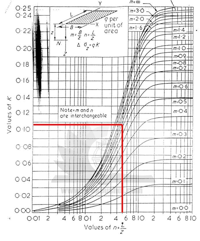
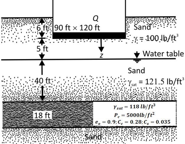
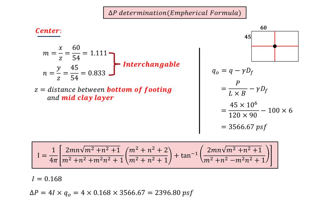
59 SETTLEMENT OF MAT FOOTING Basically same as individual footing (Single Footing), difference is in individual footing we have calculated one settlement but in mat footing we have to calculate two settlement 1. Settlement in corner 2. Settlement in center As individual footing is generally small in size, so its settlement in corner and settlement in center is almost equal. So we have calculated it in one time In mat footing, as it is large in size, their settlement in corner and center varies. So we have to calculate two settlements. For this variable settlement in corner and center extra stress develops. So we can t neglect it. For Mat Foundation Empherical Formula Fadum Chart Newmark s Influence Chart etc. 59 P a g e
60 60 P a g e

61 61 P a g e

62 62 P a g e
63 63 P a g e


64 Solution: 64 P a g e

65 65 P a g e

66 66 P a g e

67 67 P a g e
68 68 P a g e

69 69 P a g e

70 Solution: 70 P a g e

71 71 P a g e

72 CHAPTER 7 STRUCTURAL DESIGN OF FOUNDATION 72 P a g e
73 Design of Isolated Footing Step 1: Footing size Column load (DL+LL) = P Considering self weight of footing is 3% of column load. P X 1.03 # Footing area, A = (rounded value) q a (7.1) # Width of footing, B = A (for square footing) (7.2) # Net under pressure producing shear and bending, q net = 1.2Dl+1.6LL A # Assume any thickness = t Assuming t : Step 2: Punching Shear Check Footing length Thickness (7.3) # Punching Shear: a V = P- a+d (b+d) 144 # Resistive/ Allowable Shear: x q net (7.4) b Here, a,b = column dimension d = t-3 (3 clear cover at footing) V = 2 f c b o d (WSD) (7.5) V = 4 f c b o d (USD) (7.6) * b o = 2(a+d) + 2(b+d) (7.7) * If resistive/ allowable shear is greater than punching shear than ok. If smaller than increase thickness. Step 3: Beam Shear Check # Beam Shear: d d o V = q net d 0` (7.8) # Resistive/ Allowable Shear: V = 1.1 f c b o d (WSD) (7.9) V = 2 f c b o d (USD) (7.10) Step 4: Moment calculation Moment, M = q net L 2 2 For short direction, M S For long direction, M L (For square footing both side is equal, So moment will be same.) L 73 P a g e
74 Step 5: Reinforcement calculation WSD method: # n = E S E C = E S f c (7.11) # r = f s f c = 04f y 045f c (7.12) # k = n n+r # J = 1 - K 3 (7.13) (7.14) # R = f c kj (7.15) 2 # d = M Rb # A s = M f s Jd (7.16) (7.17) # A s min = 200 f y bd (7.18) USD method: f #r max = 0.85β c ε u 1 (7.19) ε u +ε y f y # R = r max f y (1-0.59r max f y f c ) (7.20) # d = M Rb (7.21) # A s = M 0.9f y (d a 2 ) check. a = A S f y 0.85f c b (7.22) Reinforcement at band width: Band width, β = L B A S in band width = A s x 2 β +1 (7.23) (7.24) Detailing: Figure 7.1: Detailing of Footing 74 P a g e

75 Design of Combined Footing Problem 7.1: Given Data: Column 1: Column 2: Size: 16 X 20 Size: 20 X 20 Dead Load: 150 kips Dead Load: 230 kips Live Load: 100 Kips Live Load: 180 Kips Center to center distance between columns: 15 Limited length from column 1 to edge: 3 Depth of foundation: 5 Allowable Bearing capacity of soil: 6 ksf Concrete compressive strength: 3ksi Yield strength of steel: 60 ksi Design the footing Solution: Step 1: Calculation of footing size Assume the average unit weight of concrete and soil filling 5ʹ from EGl is = 125 psf 2 So pressure due to soil and concrete = 5 X 125 = 625 psf Available bearing pressure of soil for footing, q a = = 5375 psf = 5.375ksf Required footing are = Dl+LL q a = ( ) Now we have to find the resultant of column loads. Distance from the left column: X X15 ( ) = sft = 9.32ʹ So the length existing of left side of the resultant force point is = So, total length is = 24.64ʹ. Required width = Size of the combined footing is 25ʹX5ʹ Select 25ʹ = 4.912ʹ Select 5ʹ 75 P a g e

76 Step 2: Draw SFD & BMD of the Footing Factored load on exterior column = 1.2 x x 100 = 320K Factored load on exterior column = 1.2 x x 180 = 564K Total Load Net upward ultimate pressure = = = 7.232K/ft Area of footing 25 x 5 Width of footing = 5ʹ Longitudinal load per feet = x 5 = 36.16ʹ 76 P a g e
77 Step 3: Design Beam & punching Shear Let thickness of footing = 25ʺ+5ʺ=30ʺ so d = 30-3 = 27ʺ Beam Shear check: Allowable shear = 2 f c Bd = 2 x 075 x 3000 x (5x12) x 27 / 1000 = kip According to the Shear force diagram, maximum shear force occurs at the left side of the interior support. So the shear force at 27ʺ from the interior support is = kip > kip (Not Ok) 77 P a g e
78 Increase the footing thickness. Try t = 40ʺ. So, d = 40-3 = 37ʺ Allowable shear = 2 f c Bd = 2 x 075 x 3000 x (5x12) x 37 / 1000 = k Shear force at 37ʺ from the interior support is = kip < kip (Ok) Punching Shear check: Punching Shear is resisted by an area on which column sides down scratching the footing. For a column, the area of punching is composed of four vertical surface that have width equal to column dimension + d/2 Allowable shear = 4 f c b 0 d = 4 x.75 x 3000 x [2{16+37/2} + 2{20+37/2}] x 37 = 851K Resisting Shear = Column load upward force = x ( 16+37/2 ) x ( 20+37/2 ) = 273.3kip << 851kip (OK) Step 4:Reinforcement Calculation Longitudinal direction: According to bending moment diagram, maximum ve moment = Kip. Assume, a = 1.5 thus A S = M = x 1000 x 12 fy (d a/2) Check a, a = A Sf y.85f c b = x x 3000 x 5 x 12 = Assume a = 1.4, thus A S =.9 x x (37 1.5/2) = 3.553in2 M = x 1000 x 12 fy (d a/2) Check a, a = A Sf y = x = 1.39 (ok).85f c b.85 x 3000 x 5 x 12.9 x x (37 1.4/2) = 3.548in2 According to bending moment diagram, maximum +ve moment = Kip Assume, a = 1.9 thus A S = M = x 1000 x 12 fy (d a/2) Check a, a = A Sf y = x = 1.86 = 1.9 (ok).85f c b.85 x 3000 x 5 x 12.9 x x (37 1.9/2) = 4.753in2 Minimum reinforcement: A s min = 3 x A s min = f c bd 3 x x 12 x 37 = f y bd 200 x 5 x 12 x 37 = f y = 7.4 in 2 = in 2 So use A s 7.4 in2 both in top and bottom along long direction. If we use #6 or 20, we have to provide 7.4/.44 = 16.81=17pc. Use 17-#6 bar along long direction both at top and bottom. Transverse direction: 78 P a g e
79 Under interior column: Transverse length = x 37/2 = 57 = 4.75 Width of footing = 5 Column Load = 564 K Upward pressure from soil along transverse span direction = 564/5 = k/ft Reinforcement is designed for moment at the face of the column, where bending moment, M = wl 2 /2 = x /2 = Assume, a =.4 thus A S = M = x 1000 x 12 fy (d a/2) Check a, a = A Sf y = x =.37 =.4 (ok).85f c b.85 x 3000 x 5 x 12.9 x x (37.4/2) = 0.946in2 Minimum reinforcement: A s min = 3 x A s min = f c bd 3 x x 37 = = in 2 f y bd 200 x 57 x 37 = = 7.03 in 2 f y Use 7.03 in 2 over longitudinal bar under interior column along 4.75 Use 16-#6 under interior column. Under exterior column: Transverse length = x 37/2 = 53 = Width of footing = 5 Column Load = 340 K Upward pressure from soil along transverse span direction = 340/5 = 68 k/ft Reinforcement is designed for moment at the face of the column, where bending moment, M = wl 2 /2 = 68 x /2 = Assume, a =.23 thus A S = M = x 1000 x 12 fy (d a/2) Check a, a = A Sf y = x =.22 =.23 (ok).85f c b.85 x 3000 x 5 x 12.9 x x (37.23/2) = 0.569in2 79 P a g e
80 Minimum reinforcement: A s min = 3 x A s min = f c bd 3 x 3000 x 53 x 37 = = 5.37 in 2 f y bd 200 x 53 x 37 = = 6.54 in 2 f y Use 6.54 in 2 over longitudinal bar under interior column along Use 15-#6 under exterior column. Step 4: Detailing Design of Mat Foundation 80 P a g e
81 Problem 7.2: A six storied residential building is supported on 16 columns arranged as shown in plan in Fig. Three sized columns used, C1 = 14'' * 14'', C2 = 14'' * 16''& C3 = 20'' * 20''. For column C1, C2 and C3 the dead loads are: 241Kip, 401Kip and 673kip and live loads are: 47Kip, 89Kip and 168Kip. Concrete compressive strength is 3500 psi and Steel yield strength is psi. Design the mat foundation. Solution Determination of Mat thickness by punching shear Punching shear check for corner column C1 Ultimate Load P U = 1.2 x DL x LL = 1.2* *47 =364.4 kip =364 kip 81 P a g e
82 d Punching perimeter, b 0 37 * 4 2 = (148+2 d) in According to ACI Code, V c Vu Where, V c = nominal shear strength of concrete = factored shear strength of concrete V u We know, V c = 4 f c b 0.d = 4 x 0.85 * 3500 *(148 2d) [b 0 = (37+d/2)*4] *(148 2d) * d = kip 1000 Vu = Pu = 364 kip X (148 2d) Xd = = (148+2d)* d = 2d 2 148d By solving the equation d 1= 10.69'' d 2 = '' d 10.69'' Select for design, d=12'' With a minimum cover of 3 inch over the steel reinforcement and 1 inch diameter steel bars, the total slab thickness, h = = 16'' Punching Shear for Exterior Column C2 Ultimate Load P u = 1.2 dead load live load = 1.2* *89 = kip=624 kip d Punching perimeter, b 0 37 * 2 + (16+d)*2 2 = (148+2d) +32+2d = (180+4d) in According to ACI Code, 82 P a g e
83 We know, V c Vu Where, V c = nominal shear strength of concrete Vu = factored shear strength of concrete V c = 4 f c b 0.d = 4 * 0.85* 3500 *(180 4d) [b 0 = (37+d/2)*2+ (16+d)*2] = * (180+4d) * d lb *(180 4d)* d = kip 1000 V u = P u = 624 kip *(176 4d)* d = = (180+4d) d = 4d 2 180d By solving the equation d 1= 13.29'' d 2 = '' d 13.29'' Select for design, d = 14'' With a minimum cover of 3 inch over the steel reinforcement and 1 inch diameter steel bars, the total slab thickness, h = = 18'' Punching Shear for Interior Column C3 Ultimate Load P u = 1.2 dead load live load = 1.2* *168 = kip=1076 kip Punching perimeter, b 0 20 d * 4 = (80+4d) = (80+4d) in According to ACI Code, V c Vu Where, V c = nominal shear strength of concrete Vu = factored shear strength of concrete We know, V c = 4 f c b 0.d = 4 * 0.85 * 3500 *(20 d)* 4 *d [b 0 = (37+d/2)*2+ (16+d)*2] = * (80+4d) * d lb 83 P a g e


84 201.15*(80 4d)* d = kip 1000 Vu = Pu = 1076 kip *(80 4d)* d = = (80+4d) d = 4d 2 80d By solving the equation d 1= 27.92'' d 2 = '' d 27.92'' Select for design, d= 28'' With a minimum cover of 3 inch over the steel reinforcement and 1 inch diameter steel bars, the total slab thickness, h = = 32'' Final Selection of Mat thickness Mat thickness for Column C1 = 16'' C2 = 18'' C3 = 32'' So, the thickness of mat foundation is equal to 32'' Steel Calculation: Load diagram for Side Strip of mat foundation (strip size 65' X 12.5'): Load diagram: Shear and moment diagram for side strip: 84 P a g e
 y As M u a = 0.85 f c. b 101.")
85 Moment Chart for Interior panel, Length-65', Width-12.5': Panel Section Positive Moment Negative Moment Total Moment Moment k-ft k-ft/ft Section Section Total Moment k-ft Moment k-ft/ft Section Section General formula for Steel Calculation M u A s = f ( d a / 2) y As M u a = 0.85 f c. b *12 As M u A s = (Let a =2 inch); check a =.9*60(32 2 / 2) 0.85 f c. b.72* A s =0.72 in 2 = 0.85*3.5* 12 = 2 inch (ok) Minimum Steel according to ACI Code A s, min = bt Where, b = 12'' and t = total thickness of mat Minimum steel according to ACI code = *12*32 = 0.69 in 2 85 P a g e
86 Steel for Interior Panel Section Positive Steel (in 2 ) Negative Steel (in 2 ) Section # 5 5'' c/c Section # 5 5'' c/c Section # 5 Section # 5 Do the same for Mid Strip of mat foundation (strip size 65' X 20'): 86 P a g e
87 APPENDIX 87 P a g e
88 APPENDIX 1 WORK TO DO The column-beam layout plan is of a four storied residential building. Different parameters are given below. A soil test report is also provided with this Lab manual. Slab Thickness: 6 Columns C1 = 10 X 10 C2 = 12 X 12 C3 = 12 X 14 Beams B1 = 12 X 18 B2 =12 X 20 Live Load = (60 - a) psf Floor Finish = (25 + a) psf Partition Wall = (50 + a) psf ' f c = (3 + a) ksi f y = (60 - a) ksi Factor, a = (Last two digits of roll x 0.1) 1. Calculate the foundation load from each column. 2. Calculate the bearing capacity and footing size if shallow foundation is provided. 3. Calculate the bearing capacity and footing size if deep foundation is provided. 4. Calculate the bearing capacity and footing size if mat foundation is provided. 5. Calculate consolidation settlement for soil under each column and also calculate the differential settlement of columns and check the angular rotation. 6. Design the Isolated footings, Combined Footings, Mat Foundation.
89 APPENDIX 2 SOIL TEST REPORT Site Plan 89 P a g e
90 BH No. : 01 Grown Water Table: 1.90 m below SPT Bore Log 90 P a g e

91 BH No. : 02 Grown Water Table: 1.90 m below 91 P a g e

92 BH No. : 03 Grown Water Table: 1.78 m below 92 P a g e
93 Unconfined Compression Test 93 P a g e
94 Direct Shear Test 94 P a g e

95 BH No. : 01 Depth: 2.4 m to 2.85 m Consolidation Test
96 APPENDIX 3 GEO-PROPERTIES AND CORRELATIONS Unit weight from SPT Unit weight of a soil mass is the ratio of the total weight of soil to the total volume of soil. Unit Weight,, is usually determined in the laboratory by measuring the weight and volume of a relatively undisturbed soil sample obtained from a brass ring. Measuring unit weight of soil in the field may consist of a sand cone test, rubber balloon or nuclear densiometer. Empirical values for, of granular soils based on the standard penetration number, (from Bowels, Foundation Analysis). SPT Value/ N-Value γ (lb/ft 3 ) > Empirical values for, of cohesive soils based on the standard penetration number, (from Bowels,Foundation Analysis)., N-Value sat (lb/ft 3 ) Typical Soil Characteristics (from Lindeburg, Civil Engineering Reference Manual for the PE Exam, 8th ed.) Soil Type (lb/ft 3 ) sat (lb/ft 3 ) Sand, loose and uniform Sand, dense and uniform sand, loose and well graded Sand, dense and well graded glacial clay, soft glacial clay, stiff Typical Values of Soil Index Properties (from NAVFAC 7.01) Soil Type (lb/ft 3 ) sub (lb/ft 3 ) Sand; clean, uniform, fine or medium Silt; uniform, inorganic Silty Sand Sand; Well-graded Silty Sand and Gravel Sandy or Silty Clay Silty Clay with Gravel; uniform Well-graded Gravel, Sand, Silt and Clay Clay Colloidal Clay Organic Silt Organic Clay
97 Typical Soil Characteristics (from Lindeburg, Civil Engineering Reference Manual for the PE Exam, 8th ed.) Soil Type (lb/ft 3 ) sat (lb/ft 3 ) Sand, loose and uniform Sand, dense and uniform sand, loose and well graded Sand, dense and well graded glacial clay, soft glacial clay, stiff Angle of Internal Friction from SPT Angle of internal friction for a given soil is the angle on the graph (Mohr's Circle) of the shear stress and normal effective stresses at which shear failure occurs. Angle of Internal Friction,, can be determined in the laboratory by the Direct Shear Test or the Triaxial Stress Test. Typical relationships for estimating the angle of internal friction,, are as follows: Empirical values for, of granular soils based on the standard penetration number, (from Bowels,Foundation Analysis). N-Value (degrees) Relationship between, and standard penetration number for sands, (from Peck 1974, Foundation Engineering Handbook). N-Value Density of Sand (degrees) <4 Very loose < Loose Medium Dense >50 Very dense >41 Relationship between, and N-value for sands, (from Meyerhof 1956, Foundation Engineering Handbook). N-Value Density of Sand (degrees) <4 Very loose < Loose Medium Dense >50 Very dense >45 97 P a g e
98 Bearing Capacity factor from Angel of Internal Friction Bearing capacity is the ability of the underlying soil to support the foundation loads without shear failure. Bearing capacity factors are empirically derived factors used in a bearing capacity equation that usually correlates with the angle of internal friction of the soil. Terzaghi s Bearing Capacity Factors N c N q N Meyerhof Bearing Capacity Factors N c N q N Bearing Capacity Factors for Deep Foundations Meyerhof Values of N q For Driven and Drilled Piles Driven Drilled P a g e
99 Cohesion of Soil Cohesive soils are clay type soils. Cohesion is the force that holds together molecules or like particles within a soil. Cohesion, c, is usually determined in the laboratory from the Direct Shear Test. Unconfined Compressive Strength, S uc, can be determined in the laboratory using the Triaxial Test or the Unconfined Compression Test. There are also correlations for S uc with shear strength as estimated from the field using Vane Shear Tests. c = S uc /2 Where: c = cohesion, kn/m 2 (lb/ft 2 ), and S uc = unconfined compressive strength, kn/m 2 (lb/ft 2 ). Guide for Consistency of Fine-Grained Soil, N-value Estimated Consistency S uc (tons/ft 2 ) <2 Very Soft < Soft Medium Stiff Very Stiff >30 Hard > 4 Empirical Values for Consistency of Cohesive Soil, (from Foundation Analysis, Bowels) Estimated N-value Consistency S uc (kips/ft 2 ) 0-2 Very Soft Soft Medium Stiff Very Stiff >32 Hard >8 Typical Strength Characteristics (from Lindeburg, Civil Engineering Reference Manual for the PE Exam, 8th ed.) USCS Soil Group c, as compacted (lb/ft 2 ) c, saturated (lb/ft 2 ) GW 0 0 GP 0 0 GM - - GC - - SW - - SP - - SM SM-SC SC ML ML-CL CL OL - - MH P a g e
100 CH Factor of Safety Foundatation Analysis by Bowels has good recommendations for safety factors. He evaluates uncertainties and assigns a factor of safety by taking into account the following: 1. Magnitude of damages (loss of life and property damage) 2. Relative cost of increasing or decreasing the factor of safety 3. Relative change in probability of failure by changing the factor of safety 4. Reliability of soil data 5. Construction tolerances 6. Changes in soil properties due to construction operations 7. Accuracy (or approximations used) in developing design/ analysis methods Typical values of customary safety factors, F.S., as presented by Bowels. Failure Mode Foundation Type F.S. Shear Earthwork for Dams, Fills, etc Shear Retaining Walls Shear Sheetpiling, Cofferdams Shear Braced Excavations (Temporary) Shear Spread Footings 2-3 Shear Mat Footings Shear Uplift for Footings Seepage Uplift, heaving Seepage Piping 3-5 Other customary factors of safety, F.S., used are: 1.5 for retaining walls overturning with granular backfill 2.0 for retaining walls overturning with cohesive backfill 1.5 for retaining walls sliding with active earth pressures 2.0 for retaining walls sliding with passive earth pressures Lateral Earth Pressure Coefficient for Soils Piles NAVFAC: USACE: Broms: Bowles: Nordlund: for a single displacement pile in compression for compression piles in sand that are not pre-bored, jetted or vibrated 1.0 for same conditions except silt higher values are for displacement piles for low density to high density steel low density to high density concrete low density to high density timber Lower values for silty sands, and higher values for other soils uses charts to identify the value for lateral earth pressure coefficients, k, based on the angle of internal friction,. Ranges from 0.25 to P a g e
101 Mansure & Hunter: for steel pipe piles for H piles for precast concrete piles Retaining Walls K = (1 - sin )/(1 + sin ) for active earth pressures K = (1 + sin )/(1 - sin ) for passive earth pressures K = 1 - sin for at-rest earth pressures where = angle of internal friction of the soil (degrees) Young's Modulus of Soil The modulus of elasticity or Young's modulus of a soil is an elastic soil parameter most commonly used in the estimation of settlement from static loads. Young's soil modulus, E s, may be estimated from empirical correlations, laboratory test results on undisturbed specimens and results of field tests. Laboratory tests that may be used to estimate the soil modulus are the triaxial unconsolidated undrained compression or the triaxial consolidated undrained compression tests. Field tests include the plate load test, cone penetration test, standard penetration test (SPT) and the pressuremeter test. Empirical correlations summarized from USACE EM is presented below: E s = K c C u where: E s = Young's soil modulus (tsf) K c = correlation factor C u = undrained shear strength, tsf Typical Elastic Moduli of soils based on soil type and consistency/ density, (from USACE, Settlement Analysis). Soil E s (tsf) very soft clay 5-50 soft clay medium clay stiff clay, silty clay sandy clay clay shale loose sand dense sand dense sand and gravel silty sand P a g e
102 APPENDIX- 4 LAB REPORT FORMAT 1. All students must have a same colored printed cover page. The design of cover page is provided with the lab manual. Students have to compose only the course teacher s name and designation ant their information. 2. An index is provided. It should be printed and set after the cover page. Table may be filled up by pen during each submission after test. 3. Each report must have a common printed top page. Only the experiment name and no. and the date may be filled up by pen. A top page design is provided. 4. A4 papers have to be used for preparing the lab report. Writing should be done with pen. Pencil may be used for any kind of sketch. 102 P a g e

103 CE 442 Geotechnical Engineering SessionalII (Foundation Design Manual) Submitted to Course Teacher(s) Name. Designation & Name.. Designation. Submitted by Student Name Student s ID.. Year/ Semester.. Group 103 P a g e
104 INDEX Expt. No. Topic Date of Submission Signature Comments Page No. Page 104
 Name. Designation")
105 CE 442 Geotechnical Engineering Sessional-I (Lab Report) Experiment No. : Experiment Name : Date of Performance : Date of Submission : Submitted to Course Teacher(s) Name. Designation & Name.. Designation. Submitted by Student Name Student s ID.. Year/ Semester.. Group Page 105
106 Appendix 5 Lab Instructions 1. All students must have to be present at design class just in time. 2. All students must have to submit the lab report just after the entrance and before the class start. 3. Lab reports have to be submitted serially according to Student s ID. 4. All students must have to bring the lab manual in the class. 5. Students have to bring design pad, pen pencil, scale and calculator in every class. Page 106

107 Page 107
The Bearing Capacity of Soils. Dr Omar Al Hattamleh
 The Bearing Capacity of Soils Dr Omar Al Hattamleh Example of Bearing Capacity Failure Omar Play the move of bearing Capacity failure The Philippine one Transcona Grain Silos Failure - Canada The Bearing
Foundation Engineering Prof. Dr. N. K. Samadhiya Department of Civil Engineering Indian Institute of Technology Roorkee
 Foundation Engineering Prof. Dr. N. K. Samadhiya Department of Civil Engineering Indian Institute of Technology Roorkee Module - 01 Lecture - 01 Shallow Foundation (Refer Slide Time: 00:19) Good morning.
Reinforced Soil Structures Reinforced Soil Walls. Prof K. Rajagopal Department of Civil Engineering IIT Madras, Chennai
 Geosynthetics and Reinforced Soil Structures Reinforced Soil Walls continued Prof K. Rajagopal Department of Civil Engineering IIT Madras, Chennai e-mail: gopalkr@iitm.ac.inac in Outline of the Lecture
Foundation Engineering Prof. Dr N.K. Samadhiya Department of Civil Engineering Indian Institute of Technology Roorkee
 Foundation Engineering Prof. Dr N.K. Samadhiya Department of Civil Engineering Indian Institute of Technology Roorkee Module 01 Lecture - 03 Shallow Foundation So, in the last lecture, we discussed the
BEARING CAPACITY SHALLOW AND DEEP FOUNDATIONS
 BEARING CAPACITY SHALLOW AND DEEP FOUNDATIONS CONTENTS: 1.0 INTRODUCTION 2.0 SHALLOW FOUNDATIONS 2.1 Design criteria 2.2 Spreading load 2.3 Types of foundations 2.4 Ground failure modes 2.5 Definitions
Deep Foundations 2. Load Capacity of a Single Pile
 Deep Foundations 2 Load Capacity of a Single Pile All calculations of pile capacity are approximate because it is almost impossible to account for the variability of soil types and the differences in the
Bearing Capacity Of Shallow Foundation
 Bearing Capacity Of Shallow Foundation Bearing Capacity Of Shallow Foundation * A foundation is required for distributing the loads of the superstructure on a large area. * The foundation should be designed
3-BEARING CAPACITY OF SOILS
 3-BEARING CAPACITY OF SOILS INTRODUCTION The soil must be capable of carrying the loads from any engineered structure placed upon it without a shear failure and with the resulting settlements being tolerable
HKIE-GD Workshop on Foundation Engineering 7 May Shallow Foundations. Dr Limin Zhang Hong Kong University of Science and Technology
 HKIE-GD Workshop on Foundation Engineering 7 May 2011 Shallow Foundations Dr Limin Zhang Hong Kong University of Science and Technology 1 Outline Summary of design requirements Load eccentricity Bearing
Chapter (5) Allowable Bearing Capacity and Settlement
 Allowable Bearing Capacity and Settlement") Chapter (5) Allowable Bearing Capacity and Settlement Introduction As we discussed previously in Chapter 3, foundations should be designed for both shear failure and allowable settlement. So the allowable
Chapter (5) Allowable Bearing Capacity and Settlement Introduction As we discussed previously in Chapter 3, foundations should be designed for both shear failure and allowable settlement. So the allowable
INTI COLLEGE MALAYSIA
 EGC373 (F) / Page 1 of 5 INTI COLLEGE MALAYSIA UK DEGREE TRANSFER PROGRAMME INTI ADELAIDE TRANSFER PROGRAMME EGC 373: FOUNDATION ENGINEERING FINAL EXAMINATION : AUGUST 00 SESSION This paper consists of
Chapter 6 Bearing Capacity
 Chapter 6 Bearing Capacity 6-1. Scope This chapter provides guidance for the determination of the ultimate and allowable bearing stress values for foundations on rock. The chapter is subdivided into four
Chapter (3) Ultimate Bearing Capacity of Shallow Foundations
 Ultimate Bearing Capacity of Shallow Foundations") Chapter (3) Ultimate Bearing Capacity of Shallow Foundations Introduction To perform satisfactorily, shallow foundations must have two main characteristics: 1. They have to be safe against overall shear
Chapter (3) Ultimate Bearing Capacity of Shallow Foundations Introduction To perform satisfactorily, shallow foundations must have two main characteristics: 1. They have to be safe against overall shear
Foundations with D f equal to 3 to 4 times the width may be defined as shallow foundations. TWO MAIN CHARACTERISTICS ULTIMATE BEARING CAPACITY
 oundation Analysis oundations with D f eual to 3 to 4 times the width may be defined as shallow foundations. TWO MAI CHARACTERISTICS o Safe against overall shear failure o Cannot undergo excessive displacement,
INTRODUCTION TO STATIC ANALYSIS PDPI 2013
 INTRODUCTION TO STATIC ANALYSIS PDPI 2013 What is Pile Capacity? When we load a pile until IT Fails what is IT Strength Considerations Two Failure Modes 1. Pile structural failure controlled by allowable
Introduction to Soil Mechanics
 Introduction to Soil Mechanics Sela Sode and Colin Jones WILEY Blackwell Contents Preface Dedication and Acknowledgments List of Symbols Soil Structure 1.1 Volume relationships 1.1.1 Voids ratio (e) 1.1.2
CHAPTER 8 CALCULATION THEORY
 CHAPTER 8 CALCULATION THEORY. Volume 2 CHAPTER 8 CALCULATION THEORY Detailed in this chapter: the theories behind the program the equations and methods that are use to perform the analyses. CONTENTS CHAPTER
water proofing will relatively long time fully completed) be provided 10 storey building (15x25m) original GWT position 1 sat = 20 kn/m 3
 be provided 10 storey building (15x25m) original GWT position 1 sat = 20 kn/m 3") P1 Question: An excavation will be made for a ten storey 15x25 m building. Temporary support of earth pressure and water pressure will be made by deep secant cantilever pile wall. The gross pressure due
P1 Question: An excavation will be made for a ten storey 15x25 m building. Temporary support of earth pressure and water pressure will be made by deep secant cantilever pile wall. The gross pressure due
Liquefaction and Foundations
 Liquefaction and Foundations Amit Prashant Indian Institute of Technology Gandhinagar Short Course on Seismic Design of Reinforced Concrete Buildings 26 30 November, 2012 What is Liquefaction? Liquefaction
Chapter (11) Pile Foundations
 Pile Foundations") Chapter (11) Introduction Piles are structural members that are made of steel, concrete, or timber. They are used to build pile foundations (classified as deep foundations) which cost more than shallow
Chapter (11) Introduction Piles are structural members that are made of steel, concrete, or timber. They are used to build pile foundations (classified as deep foundations) which cost more than shallow
GEOTECHNICAL ENGINEERING ECG 503 LECTURE NOTE ANALYSIS AND DESIGN OF RETAINING STRUCTURES
 GEOTECHNICAL ENGINEERING ECG 503 LECTURE NOTE 07 3.0 ANALYSIS AND DESIGN OF RETAINING STRUCTURES LEARNING OUTCOMES Learning outcomes: At the end of this lecture/week the students would be able to: Understand
Chapter (6) Geometric Design of Shallow Foundations
 Geometric Design of Shallow Foundations") Chapter (6) Geometric Design of Shallow Foundations Introduction As we stated in Chapter 3, foundations are considered to be shallow if if [D (3 4)B]. Shallow foundations have several advantages: minimum
Chapter (6) Geometric Design of Shallow Foundations Introduction As we stated in Chapter 3, foundations are considered to be shallow if if [D (3 4)B]. Shallow foundations have several advantages: minimum
Chapter 7: Settlement of Shallow Foundations
 Chapter 7: Settlement of Shallow Foundations Introduction The settlement of a shallow foundation can be divided into two major categories: (a) elastic, or immediate settlement and (b) consolidation settlement.
vulcanhammer.net This document downloaded from
 This document downloaded from vulcanhammer.net since 1997, your source for engineering information for the deep foundation and marine construction industries, and the historical site for Vulcan Iron Works
Design of RC Retaining Walls
 Lecture - 09 Design of RC Retaining Walls By: Prof Dr. Qaisar Ali Civil Engineering Department UET Peshawar www.drqaisarali.com 1 Topics Retaining Walls Terms Related to Retaining Walls Types of Retaining
CHAPTER 12 SHALLOW FOUNDATION I: ULTIMATE BEARING CAPACITY 12.1 INTRODUCTION
 CHAPTER 12 SHALLOW FOUNDATION I: ULTIMATE BEARING CAPACITY 12.1 INTRODUCTION It is the customary practice to regard a foundation as shallow if the depth of the foundation is less than or equal to the width
Chapter 4. Ultimate Bearing Capacity of Shallow Foundations. Omitted parts: Sections 4.7, 4.8, 4.13 Examples 4.8, 4.9, 4.
 Chapter 4 Ultimate Bearing Capacity of Shallow Foundations Omitted parts: Sections 4.7, 4.8, 4.13 Examples 4.8, 4.9, 4.12 Pages 191-194 Ultimate Bearing Capacity of Shallow Foundations To perform satisfactorily,
TABLE OF CONTENTS CHAPTER TITLE PAGE TITLE PAGE DECLARATION DEDIDATION ACKNOWLEDGEMENTS ABSTRACT ABSTRAK
 TABLE OF CONTENTS CHAPTER TITLE PAGE TITLE PAGE DECLARATION DEDIDATION ACKNOWLEDGEMENTS ABSTRACT ABSTRAK TABLE OF CONTENTS LIST OF TABLE LIST OF FIGURES LIST OF SYMBOLS LIST OF APENDICES i ii iii iv v
Introduction to Geotechnical Engineering. ground
 Introduction to Geotechnical Engineering ground 1 Typical Geotechnical Project Geo-Laboratory ~ for testing soil properties Design Office ~ for design & analysis construction site 2 Shallow Foundations
2017 Soil Mechanics II and Exercises Final Exam. 2017/7/26 (Wed) 10:00-12:00 Kyotsu 4 Lecture room
 10:00-12:00 Kyotsu 4 Lecture room") 2017 Soil Mechanics II and Exercises Final Exam 2017/7/26 (Wed) 10:00-12:00 Kyotsu 4 Lecture room Attention: The exam consists of five questions for which you are provided with five answer sheets. Write
2017 Soil Mechanics II and Exercises Final Exam 2017/7/26 (Wed) 10:00-12:00 Kyotsu 4 Lecture room Attention: The exam consists of five questions for which you are provided with five answer sheets. Write
PRINCIPLES OF GEOTECHNICAL ENGINEERING
 PRINCIPLES OF GEOTECHNICAL ENGINEERING Fourth Edition BRAJA M. DAS California State University, Sacramento I(T)P Boston Albany Bonn Cincinnati London Madrid Melbourne Mexico City New York Paris San Francisco
SHEAR STRENGTH OF SOIL
 Soil Failure Criteria SHEAR STRENGTH OF SOIL Knowledge about the shear strength of soil important for the analysis of: Bearing capacity of foundations, Slope stability, Lateral pressure on retaining structures,
SHEET PILE WALLS. Mehdi Mokhberi Islamic Azad University
 SHEET PILE WALLS Mehdi Mokhberi Islamic Azad University Lateral Support In geotechnical engineering, it is often necessary to prevent lateral soil movements. Tie rod Anchor Sheet pile Cantilever retaining
8.1. What is meant by the shear strength of soils? Solution 8.1 Shear strength of a soil is its internal resistance to shearing stresses.
 8.1. What is meant by the shear strength of soils? Solution 8.1 Shear strength of a soil is its internal resistance to shearing stresses. 8.2. Some soils show a peak shear strength. Why and what type(s)
UNIT II SHALLOW FOUNDATION
 Introduction UNIT II SHALLOW FOUNDATION A foundation is a integral part of the structure which transfer the load of the superstructure to the soil. A foundation is that member which provides support for
D1. A normally consolidated clay has the following void ratio e versus effective stress σ relationship obtained in an oedometer test.
 (d) COMPRESSIBILITY AND CONSOLIDATION D1. A normally consolidated clay has the following void ratio e versus effective stress σ relationship obtained in an oedometer test. (a) Plot the e - σ curve. (b)
This document downloaded from vulcanhammer.net vulcanhammer.info Chet Aero Marine
 This document downloaded from vulcanhammer.net vulcanhammer.info Chet Aero Marine Don t forget to visit our companion site http://www.vulcanhammer.org Use subject to the terms and conditions of the respective
The theories to estimate lateral earth pressure due to a strip surcharge loading will
 Chapter LITERATURE REVIEW The theories to estimate lateral earth pressure due to a strip surcharge loading will be introduced in this chapter. Commonly geotechnical engineers apply the equations suggested
OP-13. PROCEDURES FOR DESIGN OF EMBANKMENT
 Page 1 of 8 WORK INSTRUCTIONS FOR ENGINEERS TYC Compiled by : LSS Checked by : GSS Approved by : OP-13. PROCEDURES FOR DESIGN OF EMBANKMENT Page of 8 13.0 13.1. OVERALL PROCEDURES This section will briefly
A Comparative Study on Bearing Capacity of Shallow Foundations in Sand from N and /
 DOI 10.1007/s40030-017-0246-7 ORIGINAL CONTRIBUTION A Comparative Study on Bearing Capacity of Shallow Foundations in Sand from N and / V. A. Sakleshpur 1 C. N. V. Satyanarayana Reddy 1 Received: 9 January
Geotechnical Properties of Soil
 Geotechnical Properties of Soil 1 Soil Texture Particle size, shape and size distribution Coarse-textured (Gravel, Sand) Fine-textured (Silt, Clay) Visibility by the naked eye (0.05 mm is the approximate
FUNDAMENTALS SOIL MECHANICS. Isao Ishibashi Hemanta Hazarika. >C\ CRC Press J Taylor & Francis Group. Taylor & Francis Group, an Informa business
 SOIL MECHANICS FUNDAMENTALS Isao Ishibashi Hemanta Hazarika >C\ CRC Press J Taylor & Francis Group Boca Raton London New York CRC Press is an imprint of the Taylor & Francis Group, an Informa business
CHAPTER ONE INTRODUCTION
 CHAPTER ONE INTRODUCTION This chapter is devoted to describe the assigned project which is the Korean Industrial School at Jenin district.it concentrates also at investigation and understanding of the
Design of a Balanced-Cantilever Bridge
 Design of a Balanced-Cantilever Bridge CL (Bridge is symmetric about CL) 0.8 L 0.2 L 0.6 L 0.2 L 0.8 L L = 80 ft Bridge Span = 2.6 L = 2.6 80 = 208 Bridge Width = 30 No. of girders = 6, Width of each girder
EN Eurocode 7. Section 3 Geotechnical Data Section 6 Spread Foundations. Trevor L.L. Orr Trinity College Dublin Ireland.
 EN 1997 1: Sections 3 and 6 Your logo Brussels, 18-20 February 2008 Dissemination of information workshop 1 EN 1997-1 Eurocode 7 Section 3 Geotechnical Data Section 6 Spread Foundations Trevor L.L. Orr
Design of a Multi-Storied RC Building
 Design of a Multi-Storied RC Building 16 14 14 3 C 1 B 1 C 2 B 2 C 3 B 3 C 4 13 B 15 (S 1 ) B 16 (S 2 ) B 17 (S 3 ) B 18 7 B 4 B 5 B 6 B 7 C 5 C 6 C 7 C 8 C 9 7 B 20 B 22 14 B 19 (S 4 ) C 10 C 11 B 23
file:///d /suhasini/suha/office/html2pdf/ _editable/slides/module%202/lecture%206/6.1/1.html[3/9/2012 4:09:25 PM]
![file:///d /suhasini/suha/office/html2pdf/ _editable/slides/module%202/lecture%206/6.1/1.html[3/9/2012 4:09:25 PM]](/thumbs/96/126781421.jpg "file:///d /suhasini/suha/office/html2pdf/ _editable/slides/module%202/lecture%206/6.1/1.html[3/9/2012 4:09:25 PM]") Objectives_template Objectives In this section you will learn the following Introduction Different Theories of Earth Pressure Lateral Earth Pressure For At Rest Condition Movement of the Wall Different
Objectives_template Objectives In this section you will learn the following Introduction Different Theories of Earth Pressure Lateral Earth Pressure For At Rest Condition Movement of the Wall Different
Technical Supplement 14Q. Abutment Design for Small Bridges. (210 VI NEH, August 2007)
") Technical Supplement 14Q (10 VI NEH, August 007) Issued August 007 Cover photo: Design of abutments for small bridges reuires geotechnical analysis. Advisory Note Techniues and approaches contained in
Technical Supplement 14Q (10 VI NEH, August 007) Issued August 007 Cover photo: Design of abutments for small bridges reuires geotechnical analysis. Advisory Note Techniues and approaches contained in
Topics. Module 3 Lecture 10 SHALLOW FOUNDATIONS: ULTIMATE BEARING CAPACITY NPTEL ADVANCED FOUNDATION ENGINEERING-I
 Topics Module 3 Lecture 10 SHALLOW FOUNDATIONS: ULTIMATE BEARING CAPACITY 1.1 THE GENERAL BEARING CAPACITY EQUATION Bearing Capacity Factors General Comments 1.2 EFFECT OF SOIL COMPRESSIBILITY 1.3 ECCENTRICALLY
In-class Exercise. Problem: Select load factors for the Strength I and Service I Limit States for the. Loading Diagram for Student Exercise
 In-class Exercise Problem: Select load factors for the Strength I and Service I Limit States for the problem illustrated below. Loading Diagram for Student Exercise For this exercise, complete the following
 QUESTION BANK DEPARTMENT: CIVIL SUBJECT CODE / Name: CE 2251 / SOIL MECHANICS SEMESTER: IV UNIT 1- INTRODUCTION PART - A (2 marks) 1. Distinguish between Residual and Transported soil. (AUC May/June 2012)
Objectives. In this section you will learn the following. Development of Bearing Capacity Theory. Terzaghi's Bearing Capacity Theory
 Objectives In this section you will learn the following Development of Bearing Capacity Theory Terzaghi's Bearing Capacity Theory Assumptions in Terzaghi s Bearing Capacity Theory. Meyerhof's Bearing Capacity
Soil Mechanics Prof. B.V.S. Viswanathan Department of Civil Engineering Indian Institute of Technology, Bombay Lecture 51 Earth Pressure Theories II
 Soil Mechanics Prof. B.V.S. Viswanathan Department of Civil Engineering Indian Institute of Technology, Bombay Lecture 51 Earth Pressure Theories II Welcome to lecture number two on earth pressure theories.
Class Principles of Foundation Engineering CEE430/530
 Class Principles of Foundation Engineering CEE430/530 1-1 General Information Lecturer: Scott A. Barnhill, P.E. Lecture Time: Thursday, 7:10 pm to 9:50 pm Classroom: Kaufmann, Room 224 Office Hour: I have
Boreholes. Implementation. Boring. Boreholes may be excavated by one of these methods: 1. Auger Boring 2. Wash Boring 3.
 Implementation Boreholes 1. Auger Boring 2. Wash Boring 3. Rotary Drilling Boring Boreholes may be excavated by one of these methods: 4. Percussion Drilling The right choice of method depends on: Ground
Chapter 5 Shear Strength of Soil
 Page 5 Chapter 5 Shear Strength of Soil. The internal resistance per unit area that the soil mass can offer to resist failure and sliding along any plane inside it is called (a) strength (b) shear strength
Geotechnical Indications Of Eastern Bypass Area In Port Harcourt, Niger Delta
 Geotechnical Indications Of Eastern Bypass Area In Port Harcourt, Niger Delta Warmate Tamunonengiyeofori Geostrat International Services Limited, Rivers State, Nigeria www.geostratinternational.com info@geostratinternational.com,
SOIL MECHANICS: palgrave. Principles and Practice. Graham Barnes. macmiiian THIRD EDITION
 SOIL MECHANICS: Principles and Practice THIRD EDITION Graham Barnes palgrave macmiiian 'running Contents Preface xii Fine soil 19 List of symbols xiv Mass structure 21 Note on units xix Degree of weathering
Supplementary Problems for Chapter 7
 Supplementary Problems for Chapter 7 Problem 7.1 consolidation test has been carried out on a standard 19 mm thick clay sample. The oedometer s deflection gauge indicated 1.66 mm, just before the removal
Practical Design to Eurocode 2. The webinar will start at 12.30
 Practical Design to Eurocode 2 The webinar will start at 12.30 Course Outline Lecture Date Speaker Title 1 21 Sep Jenny Burridge Introduction, Background and Codes 2 28 Sep Charles Goodchild EC2 Background,
Theory of Shear Strength
 MAJ 1013 ADVANCED SOIL MECHANICS Theory of Shear Strength Prepared by, Dr. Hetty 1 Strength of different materials Steel Concrete Soil Tensile strength Compressive strength Shear strength Complex behavior
APPENDIX F CORRELATION EQUATIONS. F 1 In-Situ Tests
 APPENDIX F 1 APPENDIX F CORRELATION EQUATIONS F 1 In-Situ Tests 1. SPT (1) Sand (Hatanaka and Uchida, 1996), = effective vertical stress = effective friction angle = atmosphere pressure (Shmertmann, 1975)
Theory of Shear Strength
 SKAA 1713 SOIL MECHANICS Theory of Shear Strength Prepared by, Dr. Hetty 1 SOIL STRENGTH DEFINITION Shear strength of a soil is the maximum internal resistance to applied shearing forces The maximum or
Module 4 (Lecture 16) SHALLOW FOUNDATIONS: ALLOWABLE BEARING CAPACITY AND SETTLEMENT
 SHALLOW FOUNDATIONS: ALLOWABLE BEARING CAPACITY AND SETTLEMENT") Topics Module 4 (Lecture 16) SHALLOW FOUNDATIONS: ALLOWABLE BEARING CAPACITY AND SETTLEMENT 1.1 STRIP FOUNDATION ON GRANULAR SOIL REINFORCED BY METALLIC STRIPS Mode of Failure Location of Failure Surface
Topics Module 4 (Lecture 16) SHALLOW FOUNDATIONS: ALLOWABLE BEARING CAPACITY AND SETTLEMENT 1.1 STRIP FOUNDATION ON GRANULAR SOIL REINFORCED BY METALLIC STRIPS Mode of Failure Location of Failure Surface
Shear Strength of Soil
 8 Shear Strength of Soil 8 1 INTRODUCTION As a structural member, a piece of steel is capable of resisting compression, tension, and shear. Soil, however, like concrete and rock, is not capable of resisting
Engineeringmanuals. Part2
 Engineeringmanuals Part2 Engineering manuals for GEO5 programs Part 2 Chapter 1-12, refer to Engineering Manual Part 1 Chapter 13. Pile Foundations Introduction... 2 Chapter 14. Analysis of vertical load-bearing
THE STRUCTURAL DESIGN OF PILE FOUNDATIONS BASED ON LRFD FOR JAPANESE HIGHWAYS
 THE STRUCTURAL DESIGN OF PILE FOUNDATIONS BASED ON LRFD FOR JAPANESE HIGHWAYS Hideaki Nishida 1,Toshiaki Nanazawa 2, Masahiro Shirato 3, Tetsuya Kohno 4, and Mitsuaki Kitaura 5 Abstract One of the motivations
SITE INVESTIGATION 1
 SITE INVESTIGATION 1 Definition The process of determining the layers of natural soil deposits that will underlie a proposed structure and their physical properties is generally referred to as site investigation.
Landslide FE Stability Analysis
 Landslide FE Stability Analysis L. Kellezi Dept. of Geotechnical Engineering, GEO-Danish Geotechnical Institute, Denmark S. Allkja Altea & Geostudio 2000, Albania P. B. Hansen Dept. of Geotechnical Engineering,
Geotechnical Subsoil Investigation for the Design of Water Tank Foundation
 International Journal of Scientific and Research Publications, Volume 4, Issue 3, March 2014 1 Geotechnical Subsoil Investigation for the Design of Water Tank Foundation * Ngerebara Owajiokiche Dago, **
Foundation Engineering Prof. Mahendra Singh Department of Civil Engineering Indian Institute of Technology, Roorkee
 Foundation Engineering Prof. Mahendra Singh Department of Civil Engineering Indian Institute of Technology, Roorkee Module - 03 Lecture - 05 Field Tests Hello viewers, welcome back to the course on Foundation
Safe bearing capacity evaluation of the bridge site along Syafrubesi-Rasuwagadhi road, Central Nepal
 Bulletin of the Department of Geology Bulletin of the Department of Geology, Tribhuvan University, Kathmandu, Nepal, Vol. 12, 2009, pp. 95 100 Safe bearing capacity evaluation of the bridge site along
(C) Global Journal of Engineering Science and Research Management
 Global Journal of Engineering Science and Research Management") GEOTECHNCIAL ASSESSMENT OF PART OF PORT HARCOURT, NIGER DELTA FOR STRUCTURAL ANALYSIS Warmate Tamunonengiyeofori Geostrat International Services Limited, www.geostratinternational.com. *Correspondence
GEOTECHNCIAL ASSESSMENT OF PART OF PORT HARCOURT, NIGER DELTA FOR STRUCTURAL ANALYSIS Warmate Tamunonengiyeofori Geostrat International Services Limited, www.geostratinternational.com. *Correspondence
Table of Contents Chapter 1 Introduction to Geotechnical Engineering 1.1 Geotechnical Engineering 1.2 The Unique Nature of Soil and Rock Materials
 Table of Contents Chapter 1 Introduction to Geotechnical Engineering 1.1 Geotechnical Engineering 1.2 The Unique Nature of Soil and Rock Materials 1.3 Scope of This Book 1.4 Historical Development of Geotechnical
Ch 4a Stress, Strain and Shearing
 Ch. 4a - Stress, Strain, Shearing Page 1 Ch 4a Stress, Strain and Shearing Reading Assignment Ch. 4a Lecture Notes Sections 4.1-4.3 (Salgado) Other Materials Handout 4 Homework Assignment 3 Problems 4-13,
Triaxial Shear Test. o The most reliable method now available for determination of shear strength parameters.
 TOPICS Introduction Components of Shear Strength of Soils Normal and Shear Stresses on a Plane Mohr-Coulomb Failure Criterion Laboratory Shear Strength Testing Direct Shear Test Triaxial Compression Test
AB Engineering Manual
 AB Engineering Manual Allan Block Retaining Walls FOREWORD This manual presents the techniques used by Allan Block in our engineering practice to design retaining walls. It is not intended as a textbook
Chapter (4) Ultimate Bearing Capacity of Shallow Foundations (Special Cases)
 Ultimate Bearing Capacity of Shallow Foundations (Special Cases)") Chapter (4) Ultimate earing Capacity of Shallow Foundations (Special Cases) Ultimate.C. of Shallow Foundations (Special Cases) Introduction The ultimate bearing capacity theories discussed in Chapter 3
Chapter (4) Ultimate earing Capacity of Shallow Foundations (Special Cases) Ultimate.C. of Shallow Foundations (Special Cases) Introduction The ultimate bearing capacity theories discussed in Chapter 3
International Journal of Advance Engineering and Research Development. Parametric Study of Beam Slab Raft Foundation
 Scientific Journal of Impact Factor (SJIF): 4.72 International Journal of Advance Engineering and Research Development Volume 4, Issue, May-2017 Parametric Study of Beam Slab Raft Foundation Sudhir.D.Ravani
Engineer. Engineering. Engineering. (in-ja-neer ) A person trained and skilled in any of the various branches of engineering: a civil engineer
 A person trained and skilled in any of the various branches of engineering: a civil engineer") Engineer (in-ja-neer ) A person trained and skilled in any of the various branches of engineering: a civil engineer (Random House Webster s College Dictionary, 1991) CE100 Introduction to Civil Geotechnical
Engineer (in-ja-neer ) A person trained and skilled in any of the various branches of engineering: a civil engineer (Random House Webster s College Dictionary, 1991) CE100 Introduction to Civil Geotechnical
Table 3. Empirical Coefficients for BS 8002 equation. A (degrees) Rounded Sub-angular. 2 Angular. B (degrees) Uniform Moderate grading.
 Rounded Sub-angular. 2 Angular. B (degrees) Uniform Moderate grading.") Hatanaka and Uchida (1996); ' 20N 20 12N 20 ' 45 A lower bound for the above equation is given as; 12N 15 ' 45 Table 3. Empirical Coefficients for BS 8002 equation A Angularity 1) A (degrees) Rounded 0
Hatanaka and Uchida (1996); ' 20N 20 12N 20 ' 45 A lower bound for the above equation is given as; 12N 15 ' 45 Table 3. Empirical Coefficients for BS 8002 equation A Angularity 1) A (degrees) Rounded 0
DESIGN AND DETAILING OF COUNTERFORT RETAINING WALL
 DESIGN AND DETAILING OF COUNTERFORT RETAINING WALL When the height of the retaining wall exceeds about 6 m, the thickness of the stem and heel slab works out to be sufficiently large and the design becomes
PECivilExam.com. Copyright 2015 Pecivilexam.com all rights reserved- E-Book Geotechnical Depth Exam: 80 problems
 PECivilExam.com PE Civil Exam 80- Geotechnical Questions & Answers (pdf Format) For Depth Exam (Evening Session) PE Civil Depth Exam (Evening Session): This practice exam contains 80- Geotechnical questions,
Failure Modes and Bearing Capacity Estimation for Strip Foundations in C-ɸ Soils: A Numerical Study
 Failure Modes and Bearing Capacity Estimation for Strip Foundations in C-ɸ Soils: A Numerical Study Paul Akagwu, Aaron Aboshio International Science Index, Civil and Environmental Engineering waset.org/publication/10005793
Shear Strength of Soils
 Shear Strength of Soils STRESSES IN A SOIL ELEMENT t s v Analyze Effective Stresses (s ) Load carried by Soil t Where: s H t t s H s = t f = s v = s H = t = s v Stresses in a Soil Element after Figure
Analysis of the horizontal bearing capacity of a single pile
 Engineering manual No. 16 Updated: 07/2018 Analysis of the horizontal bearing capacity of a single pile Program: Soubor: Pile Demo_manual_16.gpi The objective of this engineering manual is to explain how
SHEAR STRENGTH OF SOIL
 SHEAR STRENGTH OF SOIL Necessity of studying Shear Strength of soils : Soil failure usually occurs in the form of shearing along internal surface within the soil. Shear Strength: Thus, structural strength
J. Paul Guyer, P.E., R.A.
 J. Paul Guyer, P.E., R.A. Paul Guyer is a registered mechanical engineer, civil engineer, fire protection engineer and architect with over 35 years experience in the design of buildings and related infrastructure.
Smith s Elements of Soil Mechanics
 SEOA01 28/04/2006 01:55PM Page i Smith s Elements of Soil Mechanics Eighth Edition Ian Smith Napier University, Edinburgh SEOA01 28/04/2006 01:55PM Page ii Ian Smith 2006 G. N. Smith 1968, 1971, 1974,
9.13 Fixed Earth-Support Method for Penetration into Sandy Soil
 476 Chapter 9: Sheet Pile Walls 9.13 Fixed Earth-Support Method for Penetration into y Soil When using the fixed earth support method, we assume that the toe of the pile is restrained from rotating, as
(Refer Slide Time: 01:15)
") Soil Mechanics Prof. B.V.S. Viswanathan Department of Civil Engineering Indian Institute of Technology, Bombay Lecture 56 Stability analysis of slopes II Welcome to lecture two on stability analysis of
Soil Mechanics Prof. B.V.S. Viswanathan Department of Civil Engineering Indian Institute of Technology, Bombay Lecture 56 Stability analysis of slopes II Welcome to lecture two on stability analysis of
FOUNDATION ENGINEERING UNIT V
 FOUNDATION ENGINEERING UNIT V RETAINING WALLS Plastic equilibrium in soils active and passive states Rankine s theory cohesion less and cohesive soil - Coloumb s wedge theory condition for critical failure
Module 6 Lecture 37 Evaluation of Soil Settlement - 3 Topics
 Module 6 Lecture 37 Evaluation of Soil Settlement - 3 Topics 1.2.4 Settlement Prediction in by Empirical Correlation 1.2.5 Calculation of Immediate Settlement in Granular Soil Using Simplified Strain Influence
Examples to verify and illustrate ELPLA
 Determining contact pressures, settlements, moments and shear forces of slab foundations by the method of finite elements Version 2010 Program authors: M. El Gendy A. El Gendy GEOTEC: GEOTEC Software Inc.
AB Engineering Manual
 AB Engineering Manual Allan Block Retaining Walls This manual presents the techniques used by Allan Block in our engineering practice to design retaining walls. It is not intended as a textbook of soil
Chapter (12) Instructor : Dr. Jehad Hamad
 Instructor : Dr. Jehad Hamad") Chapter (12) Instructor : Dr. Jehad Hamad 2017-2016 Chapter Outlines Shear strength in soils Direct shear test Unconfined Compression Test Tri-axial Test Shear Strength The strength of a material is the
Chapter (12) Instructor : Dr. Jehad Hamad 2017-2016 Chapter Outlines Shear strength in soils Direct shear test Unconfined Compression Test Tri-axial Test Shear Strength The strength of a material is the
*** ***! " " ) * % )!( & ' % # $. 0 1 %./ +, - 7 : %8% 9 ) 7 / ( * 7 : %8% 9 < ;14. " > /' ;-,=. / ١
 * % )!( & ' % # $. 0 1 %./ +, - 7 : %8% 9 ) 7 / ( * 7 : %8% 9 < ;14. > /' ;-,=. / ١") ١ ******!" #$ % & '!( ) % * ") +,-./ % 01. 3 ( 4 56 7/4 ) 8%9 % : 7 ;14 < 8%9 % : *7./ = ;-, >/'." Soil Permeability & Seepage ٢ Soil Permeability- Definition ٣ What is Permeability? Permeability is the
١ ******!" #$ % & '!( ) % * ") +,-./ % 01. 3 ( 4 56 7/4 ) 8%9 % : 7 ;14 < 8%9 % : *7./ = ;-, >/'." Soil Permeability & Seepage ٢ Soil Permeability- Definition ٣ What is Permeability? Permeability is the
Laboratory Testing Total & Effective Stress Analysis
 SKAA 1713 SOIL MECHANICS Laboratory Testing Total & Effective Stress Analysis Prepared by: Dr. Hetty Mohr Coulomb failure criterion with Mohr circle of stress 2 ' 2 ' ' ' 3 ' 1 ' 3 ' 1 Cot Sin c ' ' 2
Calculation of 1-D Consolidation Settlement
 Calculation of 1-D Consolidation Settlement A general theory for consolidation, incorporating threedimensional flow is complicated and only applicable to a very limited range of problems in geotechnical
Chapter 12 Subsurface Exploration
 Page 12 1 Chapter 12 Subsurface Exploration 1. The process of identifying the layers of deposits that underlie a proposed structure and their physical characteristics is generally referred to as (a) subsurface