Finite element analysis of composite structures
|
|
|
- Georgiana Coleen Barnett
- 5 years ago
- Views:
Transcription


1 Finite element analysis of composite structures Viktor Kulíšek CZCH TCHNICL UNIVRSITY IN PRU FCULTY OF MCHNICL NINRIN epartment of Production Machines and quipment PM Research Center of Manufacturing Technology RCMT

2 Overview F of composite structures 2 Introduction Typical composite applications Composite materials Fibre and matrix properties Fabrics and preforms Unidirectional composite Material properties Layered structures matrix and its implications F of composite structures lements for F of composites Stress and strength xamples
3 Introduction F of composite structures 3 Finite element analysis of composite structures The principle of F same as for the isotropic materials from the previous courses K. u = f K global stiffness matrix u global vector of nodal displacements f global vector of external equivalent nodal forces solution: u = K 1. f For composite structures more challenging in pre-processing of models and post-processing of results ue to orthotropic behaviour of material and other important parameters In this lecture, the basic approaches for modelling of long fibre reinforced plastics are discussed
4 Introduction F of composite structures 4 Important to know What are the demanded results of the simulation? (stress, displacement, natural frequencies, temperature distribution, crash behaviour, ) What is the demanded precision of results? What manufacturing technology and preforms are used for the structure? fabrics, prepregs, fibre tows unidirectional versus multidirectional preform abilities of manufacturing technology Important decisions lements type selection and geometry simplifications Modelling of composite structure full composite lay-up matrix properties homogenization


5 Introduction Composite structures - erospace 5 irbus 35XW, Premium ROTC


6 Introduction Composite structures - erospace 6


7 Introduction Composite structures - erospace 7


8 Introduction Composite structures - utomotive 8


9 Introduction Composite structures - utomotive 9


10 1 Introduction Composite structures - erospace MW I3 CFRP life module weight reduction since 213 on sale


11 Introduction Composite structures - Industry 11


12 Introduction Composite structures
13 Introduction 13 Short conclusions in terms of composite structures Usually thin components (thickness is significantly smaller than other 2 dimensions) Suitable for shell elements, beam elements Options for solid modelling limited Usually composite lay-up with layers with multiangle orientations, structures with only 1 orientation of fibres are rare Various semi-finished products used in the structures Fabrics, prepregs, rovings ifferent manufacturing technologies, different fibre volume fraction in the composite layer Various materials used in applications Fibres Matrices ll of the aforementioned influence the behaviour of the component and thereby the demands for its modelling


14 14 Composite materials emonstration layer of composite material Properties of layer is determined by type of fibre carbon, glass, boron, aramid type of matrix thermosets - epoxy, thermoplastics P, PK, PPS,... type of semi-finished product unidirectional multidirectional fibre volume fraction in the layer manufacturing technology
15 Composite materials - Fibres 15 Fibres carry the load; significantly defines the stiffness Overview of nominal properties of selected types of fibres L Youngs modulus in direction of fibre T Youngs modulus in direction perpendicular to fibre LT shear modulus of fibre s Lf tensile strength of fibre a L thermal expansion coefficient in direction of fibre l L thermal conductivity in direction of fibre lass isotropic fibre, Carbon strongly anisotropic r L L T f s Lf a L l Lf [kg.m -3 ] [Pa] [Pa] [Pa] [MPa] [K -1 ] [W.m -1.K -1 ] High-strength PN carbon ,38e-6 1 Ultra-high modulus PITCH carbon ,5e glass ,4e-6 1,35 S-glass ,6e-6 1,45 ramid ,4e-6,4


16 Composite materials - Fibres 16 IL - Mitsubishi Plastics Nippon raphite Fiber Corporation
17 Composite materials - Matrices 17 Matrix affects strength, fracture toughness affects other properties (flammability, conductivity, fatigue, biocompactibility, ) determines/restricts the manufacturing technologies Thermosets non-repeatable manufacturing process after curing no reshaping (nondestructively) longer time of curing (hours minutes) brittle materials Thermoplastics repeatable manufacturing process after heating matrix softening reshaping short time of processing (minutes) good fracture toughness

18 Composite materials - Matrices 18 Source: R, Chris. The Outlook for Thermoplastics in erospace Composites, In High- Performance Composites. Vol. 22, No. 5, 214.
19 Composite materials - Matrices 19 Matrix ensity [kg.m -3 ] [MPa] a [K -1 ] l [W/m/K] lass transition temp. [ C] poxy e-6,2,5 5 2 x Melting temp. [ C] Nonsaturated polyesters Phenolic resins e-6,3, x e-6,4,7 7 x PP e-6,17, P e-6,22, P e-6,22, PPS e-6 x PK e-6, PI 7 3 5e-6, x


20 2 Composite materials - semi-finished products Possible semi-finished products for composite applications fabrics prepregs, U tapes rovings / fibre tows chopped fibres Properties of semi-finished product influences the behavior of the unit and component (stiffness, strength) fibre orientation uni or bi-directional amount of fibres Type of semi-finished product affects the modelling approach fabrics prepregs rovings chopped fibres Source:


21 21 Composite materials - semi-finished products Fabrics plain worse drapability good strength, resistance against shift of fibres twill average drapability satin good drapability small resistance against shift of fibres


22 Composite materials - semi-finished products 22 Prepregs thermosets fabric or uni-directional and semi-cured matrix thermoplastics fabric or uni-directional and thermoplastic matrix Storage thermosets must be stored at approx. -18 C, limited lifetime thermoplastics can be stored at room temperature, without lifetime restrictions One of the highest-quality semi-finished product
23 Composite materials - semi-finished products 23 Rovings fibre tows notation 1k, 3k, 6k, k, 24k, 48k gives number of fibres in the tow (1k ~ 1 fibres) for filament winding, fibre placement, manufacturing of prepregs and fabricss


24 Composite materials 24 Short overview Internal structure of composite layer determines mechanical properties stiffness strength other From the F point of view Properties of layer described by material, thickness and orientation However, care must be taken when simplifying the semi-finished products like bi-directional fabrics into the layer properties asic unit for simulations Uni-directional layer of composite
25 25 asic computational element Properties determined by type of fibre type of matrix fibre volume fraction in the layer thickness of the layer / 1/ 1/ 1/ / / / 1/ / / / 1/ s s s s s s isotropic material / 1/ 1/ 1/ / / / 1/ / / / 1/ s s s s s s orthotropic material 1 2. Parameters:, n Parameters: x, y, z, xy, xz, yz, n xy, n xz, n yz j ji i ij Unidirectional layer of composite
26 26 Material properties must fulfil stability criterion / 1/ 1/ 1/ / / / 1/ / / / 1/ s s s s s s isotropic material / 1/ 1/ 1/ / / / 1/ / / / 1/ s s s s s s orthotropic material 1 2. Parameters:, n Parameters: x, y, z, xy, xz, yz, n xy, n xz, n yz j ji i ij j i ij >, > i >, ij > i,j=x,y,z 2 1 xz zy yz xz zx zy yz yx xy 1,5 Unidirectional layer of composite Conditions of stability
27 Unidirectional layer of composite Thin composite structures neglecting through thickness stresses plane stress model enable to simplify the model for composite laminates 27 orthotropic material model lamina material model (plane stress) 11 1/ 1 22 / / / 21 1/ 23 2 / 2 2 / / 3 3 / 3 1/ 1/ 13 1/ 23 s 11 s 22 s 33. s s 13 s / 1 2 / 1 / 21 1/ 2 2 1/ s 11 s 22 s Parameters: x, y, z, xy, xz, yz, n xy, n xz, n yz Parameters: x, y xy, n xy, ( xz, yz ) lthough 4 parameters are necessary ( x, y, xy, n xy ), the other two shear modules should be included as well due to low values of shear modulus of fibre composites to prevent unreasonable deformations of finite element model
28 28 Unidirectional layer of composite Modelling of U layer thickness material properties ( x, y, xy, n xy, xz, yz ) material orientation lements baqus orientation must be specified for not isotropic material; otherwise input will not pass solver check nsys PL if not specified, orientation is taken from the global coordinate system** Shell elements Solid elements (full orthotropic material model needed) be careful for the transverse shearing stresses eams In reality, most composite structures compose of layers (U or bi-directional) with various orientation ** for shell elements the situation is more complicated
29 Unidirectional layer of composite 29 Mechanical properties of layer Necessity to input x, y, xy, n xy, xz, yz How to get these constants? Issues From the manufacturer of semi-finished product (prepregs) From experimental measurements y computation from fibre and matrix properties and assumed fibre volume fraction (rule of mixture, micromechanics of composites) Parameters of fibres can be unknown (mostly parameters in transverse direction) Micromechanical model or rule of mixture might not correspond to the selected fibre ifferent models for isotropic fibres (glass) and orthotropic fibres Variation between the models and experimental behaviour Theoretical fibre volume fraction does not match with the fibre volume fraction of real composite component ifferent tensile and compressive modulus x of carbon fibre composites (approx. 1%)
30 Unidirectional layer of composite 3 Mechanical properties of layer Necessity to input x, y, xy, n xy, xz, yz xample of rule of mixture presented equations the most simple, not necessary the most accurate Longitudinal modulus of layer V 1V L f f f m In-plane Poisson number n Vn Vn LT f f m m Transverse modulus of layer T LT m 1V 1 f m 1V 1 f m f m f m 1 V In-plane Shear modulus m 1 V f f
31 Unidirectional layer of composite 31 Mechanical properties of layer Necessity to input x, y, xy, n xy, xz, yz Should the factors like the fibre properties be included in the selection of the mechanical model? Transverse modulus of layer* T = In-plane Shear modulus* LT = m 1 1 m ft. V f m 1 V f. 1 m flt Transverse modulus of layer T LT m 1V 1 f m 1V 1 f m f m f m 1 V In-plane Shear modulus m 1 V * quations Chamis model, CHMIS, Christos C. Simplified Composite Micromechanics quations for Strength, Fracture Toughness and nvironmental ffects. Houston, January Report No. NS TM National eronautics and Space dministration. f f
32 32 Unidirectional layer of composite Mechanical properties of layer x, y, xy, n xy, xz, yz How to calculate other parameters Z, n xz, n yz, xz, yz? yz, n yz quite problematic xy = xz = LT x = L y = z = T / 1 1 f m m V Chamis (): Tsai (): m f f f f f V V V V m f m m 4 1 / 4 3 Hashin f23 > m m m m K m m K m m K f V m f m f V m n n
33 33 Unidirectional layer of composite Mechanical properties of layer x, y, xy, n xy, xz, yz How to calculate other parameters Z, n xz, n yz, xz, yz? yz, n yz quite problematic xy = xz = LT x = L y = z = T / 1 1 f m m V Chamis (): Tsai (): m f f f f f V V V V m f m m 4 1 / 4 3 Hashin f23 > m m m m K m m K m m K f V m f m f V m n n
34 Unidirectional layer of composite 34 ffect of transverse shearing ending of rectangular beam u = F. L3 3 J bending + β. F. L transverse shearing eam of rectangular cross-section (J) modulus 1 () modulus 13 For orthotropic beam profile low stiffness in transverse shearing can be neglected when length/thickness ratio is 3 (2) and more increase of thickness not efficient, need to change material orientation Material r f [kg.m -3 ] 1 [Pa] steel [Pa] uhm/ (2 4) combination of layers and [45,-45]s

35 Layered structures & Laminates 35 Let s get to reality
36 Layered structures & Laminates 36 Real composite components composed of layers with different orientations Hand made laminates Laminates from prepregs RTM products (resin transfer moulding) Filament or tape winding products, braiding In comparison with isotropic F models Restriction of element types More time consuming preprocessing of the model More data consuming model Need to have clear idea what to do at the beginning of pre-processing Simplifications necessary, but might lead to fatal errors in modelling or postprocessing
37 Layered structures Laminate theory 37 Classical laminate theory relations between the load and deformations of the laminate plane stress state in the laminate neglecting transverse shear stresses thickness of layer is significantly smaller than other dimensions rigid interference between the layers N N N M M M x y xy x y xy xx yy xy k x k y k xy
38 38 Layered structures Laminate theory Properties of laminate can be described by matrix In general, matrix contains all components xy y x xy yy xx xy y x xy y x k k k M M M N N N k k n k k ij ij h h Q xy y x xy yy xx k xy yy xx k k k Q Q Q Q Q Q Q Q Q z Q Q Q Q Q Q Q Q Q s s s k k n k k ij ij h h Q 1 1 k k n k k ij ij h h Q
39 Layered structures matrix and its meaning 39 Full matrix 1 loading component leads to all deformation effects normal strains bending strains twisting strains shearing strains The coupled deformation effect might cause problems when simplifying modelling using the symmetry of models using the homogenized material constants N N N M M M x y xy x y xy xx yy xy k x k y k xy xx N 16 x N yy y N xy xy k M x x k M y y k M xy xy
40 Layered structures matrix and its meaning 4 ffect of composite lay-up on matrix Symmetric alanced Např.: S Symmetric balanced Např.: Např.: s Symmetric cross-ply O 66 Např.: ntisymmetric cross-ply O 66 Např.: 9 9 9
41 Layered structures first order shear theory 41 Classical laminate theory Kirchhoff First order shear theory with effect of transverse shearing N N N M M M x y xy x y xy k x k y k xx yy xy xy Nx xx N y yy N xy xy M x kx M y k y M xy kxy Q y F44 F 45 yz Qx F45 F55 xz
42 Layered structures first order shear theory 42 Transverse shearing can be neglected for very thin plates for composites, the length to thickness ratio, from which it is possible to neglect transverse shearing, is significantly higher than for isotropic materials F shells generally with FOST Nx xx N y yy N xy xy M x kx M y k y M xy kxy Q y F44 F 45 yz Qx F45 F55 xz sxx Q11 Q Q16 xx s Q Q Q yy yy s Q Q Q xy xy s yz C 44 C 45 yz s xz C k 54 C 55 xz F ij n C ij hk hk 1, i, j 4, 5 k 1 k
43 Layered structures homogenization 43 xx N 16 x N yy y N xy xy k M x x k M y y k M xy xy N. xx Nx yy xy k x k y k xy x x _ tah xx 11. Nx x _ tah t i Inverse matrix to can be used for determination of equivalent material properties of the laminate x, y, xy, n xy This approach leads to simplified modelling, but with reduced accuracy (missing the coupling between the deformations) Homogenized constants might violate the stability conditions of material model more precise xx yy xy k M x x k y k xy M x k. M o x 11 x x _ ohyb. J x_ohyb = t i 3
44 lements for F of composite structures 44 nsys F solver recommended elements layered shell elements (shell181, shell 281) layered solid-shell elements (solidshell 19) layered solid elements (solid185, solid186), beam elements 4-node layered shell element SHLL181 modelled on reference surface each node 3 translation OF and 3 rotation OF 8-node layered shell element SHLL281 (SHLL91, SHLL99)
45 lements for F of composite structures 45 nsys F solver recommended elements layered shell elements (shell181, shell 281) layered solid-shell elements (solidshell 19) layered solid elements (solid185, solid186), beam elements 8-node solid-shell element SOLSH19 Solid geometry, node 3 translation OFS ehaviour similar to shell elements It is necessary to have consistent orientation of element in thickness direction VORINT ORINT For thicker components more precise than classical shells, can be stacked through thickness In comparison with solids more precise in transverse sharing stresses
46 lements for F of composite structures 46 nsys F solver recommended elements layered shell elements (shell181, shell 281) layered solid-shell elements (solidshell 19) layered solid elements (solid185, solid186), beam elements 8-node layered solid element SOLI185 limited usage (free edge problems, ) 2-node layered solid element SOLI186
47 lements for F of composite structures 47 baqus & composites solid elements conventional shell elements continuum shell elements (solid-shell elements from previous slides) Source: baqus v6.1 ocumentation

48 lements for F of composite structures - Shells 48 Conventional shells The most common elements for modelling of components from fibre reinforced plastics Source baqus v6.1 ocumentation nable to easily define the material, orientation and thickness of every layer of lay-up Layers are modelled in the same order as were defined, stacking is in direction of shell normal the first layer is at the bottom of shell the last layer at the top surface of shell Results of shell in integration points, in every layer section points through thickness Shell are modelled on the reference surface Source Solidworks help Reference surface on midsurface Reference surface - offset from the midsurface enabling to model the ply-drops
49 lements for F of composite structures - Shells 49 asic assumptions for using shell elements each ply is modelled as homogenous, its thickness is significantly smaller in comparison with the other dimensions interface between the layers is ideally rigid, thin, the displacements of the layers through the interfaces are therefore continuous Kirchhof or First Order Shear Theory shell thickness does not change with deformation the ration of smallest dimension of shell surface to its thickness is larger than 1 stiffness of laminate in coordinates X, Y, Z of shell does not differ by more than 2 orders (might be violated in sandwich constructions) more: pdf
50 lements for F of composite structures - Shells 5 asic difference in comparison with modelling of isotropic materials Potential source of fatal errors if neglected Isotropic shells in commercial F solvers default: data stored in the top and bottom layer of the shell maximum of bending stresses safe for evaluation of strength Orthotropic shells when using default settings without enhancing the data storage to every layer layers with maximal loading might be not evaluated in terms of stress, strain and failure only top and bottom layer post-processed Works both for conventional and continuum shells If you need to investigate the stress loading of component and potential failure, you need to know the stress loading of every layer in critical area of components If deformations are needed only, this can be neglected
51 51 Strength evaluation Orthotropic materials strength differs for different modes of loading do not evaluate by isotropic approaches (von Mises stress, ) F of composite structure failure index for the first ply failure maximal stress or strain criterion Tsai-Wu, Tsai-Hill, PUCK, LRC3,LRC4 User defined criteria might be complicated to get all data of ply strengths for the criteria evaluation not every criteria is suitable for the loading mode (but still better to be used than to use von Mises stress) S4/ - glass/ V f [%] 6 62 X T [MPa] X c [MPa] Y T [MPa] Y c [MPa] S [MPa] T [%] 1,38 2,13 1C [%] 1,18 1,7 2T [%],44,2 2C [%] 2,,64 [%] 2 3,8
 solsh19, keyopt(8)= f TSIWU =,7 solsh19, keyopt(8)=1 f TSIWU =,2")
52 52 Strength evaluation Failure index f f<1 no first ply failure f=1 first ply failure o not forget to evaluate data through all the layers specified in the lay (i.e. not only from the top and bottom layer) solsh19, keyopt(8)= f TSIWU =,7 solsh19, keyopt(8)=1 f TSIWU =,2


53 53 Strength evaluation Options to model progressive damaging of composites Stiffness degradation due to damage initiation and growth baqus, nsys - Options for progressive damage implemented Source C ssociates Progressive amage of Fiber Reinforced Composites in nsys v15 Options to investigate the composites delamination Cohesive Zone Modelling Virtual Crack Closure Technique used also for simulations of debonding of adhesive joints between the components
54 Composite structures 54 Short conclusions in terms of modelling structural level Usually thin components (thickness is significantly smaller than other 2 dimensions) Suitable for shell elements, beam elements Options for solid modelling limited Usually composite lay-up with layers with multiangle orientations, structures with only 1 orientation of fibres are rare Conventional shell elements definition of full composite lay-up» material, thickness, orientation in respect to element normal specification by matrix» matrix, optionally with transverse shear stiffness specification by homogenized properties» modules of laminate
55 Composite structures 55 Short conclusions in terms of modelling structural level Usually thin components (thickness is significantly smaller than other 2 dimensions) Suitable for shell elements, beam elements Options for solid modelling limited Usually composite lay-up with layers with multiangle orientations, structures with only 1 orientation of fibres are rare Continuum shell elements definition of full composite lay-up» material, relative thickness, orientation in respect to element normal specification by homogenized properties» modules of laminate specification by matrix not applicable must be divided into sub-laminates if having more than 1 element through thickness
56 Composite structures 56 Short conclusions in terms of modelling structural level Usually thin components (thickness is significantly smaller than other 2 dimensions) Suitable for shell elements, beam elements Options for solid modelling limited Usually composite lay-up with layers with multiangle orientations, structures with only 1 orientation of fibres are rare Continuum shell elements definition of full composite lay-up» material, relative thickness, orientation in respect to element normal specification by homogenized properties» modules of laminate specification by matrix not applicable must be divided into sub-laminates if having more than 1 element through thickness


57 Composite structures 57 Lay-up specification baqus shell section composite lay-up manager (preferable)

58 Composite structures 58 Lay-up specification nsys shell section (Mechanical PL, Workbench through PL commands) nsys Composite Pre-Post graphical interface for composite materials additional plug-in to nsys, available to students of CTU in Prague! sect,1,shell,,navin1 secdata,.5,1,,3 secdata,.4,2,45,3 secdata,. 4,2,-45,3 secdata,.6,3,93 secdata,.4,2,-45,3 secdata,. 4,2,45,3 secdata,.5,2,,3! et,2,solsh19 emodif,all,type,2 emodif,all,esys,11 emodif,all,secnum,1
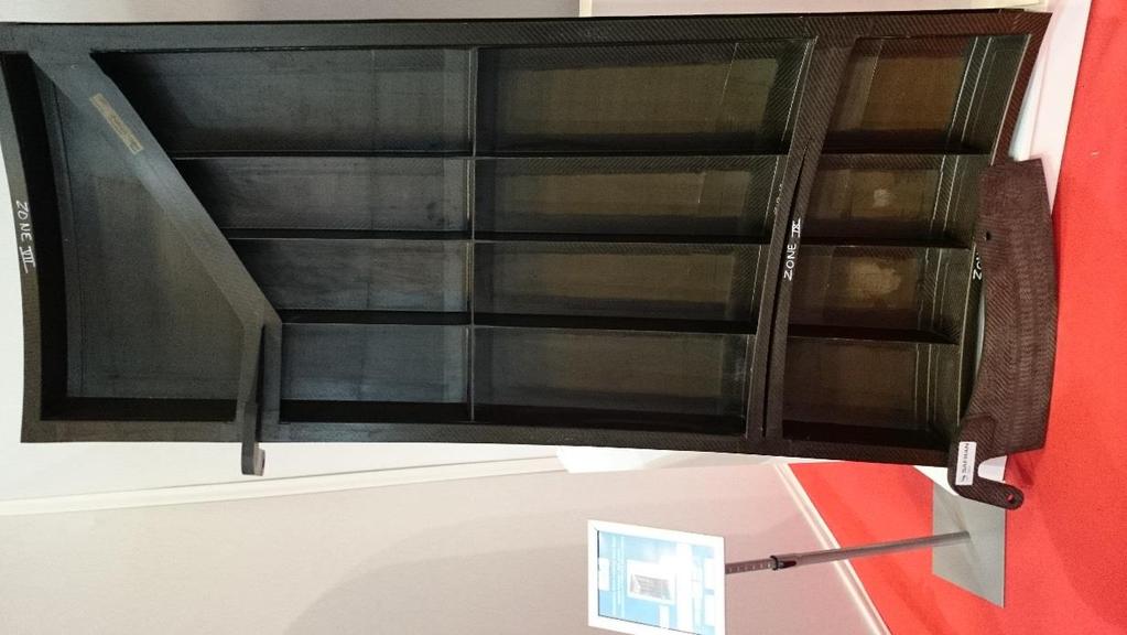
![xample 1 59 Laminate beam Laminate from U prepregs imensions 7x7 mm Lay-up [, 45, -45, 9]s high-strength](/docs-images/83/88390783/images/59-0.jpg "C/ high-modulus C/ material data from prepreg manufacturer sheets additional parameters from")
59 xample 1 59 Laminate beam Laminate from U prepregs imensions 7x7 mm Lay-up [, 45, -45, 9]s high-strength C/ high-modulus C/ material data from prepreg manufacturer sheets additional parameters from micromechanics

60 xample 1 6 Laminate beam Shell finite element model Full Lay-up specification

![acceptable Mode [-] xperiment [Hz] F [Hz] 1 42.5 46.4 2 1.5 132.](/docs-images/83/88390783/images/61-1.jpg "6 3 193.5 26.2 4 242.4 266.4 5 46.2 419.4 Mass [g] 262.5 263.8")
61 xample 1 61 Comparison with experimental results modal analysis mode shapes and its frequencies match between F and experiment acceptable Mode [-] xperiment [Hz] F [Hz] Mass [g]
62 xample 1 62 Comparison with experimental results laminate beam from HM/ U prepregs [, 45, -45, 9]s laminate modelled by 1 matrix homogenized x, y, xy, n xy, xz, yz of the lay-up 2 matrix with transverse shear stiffness (F) using first order shear theory with specified transverse stiffness most precise Mode [-] xp. [Hz] 1 [Hz] hom. const [Hz] F [Hz] bend bend tors bend bend tors
 material properties from fibre and matrix")
![parameters, assumed fibre volume fraction estimation n23, 23 xperiment F [Hz] [Hz] 59.2 596.8 833.1 797. 893.](/docs-images/83/88390783/images/63-1.jpg "3 836.7 1457.7 1442. 184.1 161.4 1873.1 1821.")
63 xample Unidirectional beam 63 Unidirectional thick-walled beam beam 74x3x2 material: ultra-high modulus carbon / epoxy composite modelled by solid elements C38I (baqus) material properties from fibre and matrix parameters, assumed fibre volume fraction estimation n23, 23 xperiment F [Hz] [Hz] first bending mode shapes with good precision; torsional mode more inaccurate


64 xample beam profile coupons 64 ffect of geometry mode shapes of free beam m1 m2 xperiment [Hz] Model 1 [Hz] Model 2 [Hz] #1 #2 #3 #4 due to the geometry simplifications, shell model or even continuum shell model with 1 element per thickness not working for the mode shapes and frequency prediction except the bending mode more detailed geometry from continuum shells in good relation with experiment both models work for the bending modes in a similar way


![shells [Hz] 484 1196 98 F one](/docs-images/83/88390783/images/65-6.jpg "shell [Hz] 344 669 59 MF solid")
65 xample beam profile coupons 65 ffect of element selection important for hybrid composites with damping layers that have significantly higher compliance separation of elements for damping material necessary ~ 4 MPa x ~ 13 Pa, y,z ~ 5 Pa m1 m2 m3 xperiment [Hz] F solid shells [Hz] F one shell [Hz] MF solid shells, mat hom [Hz]


![F_1 [Hz] 457 585 95 178 xp_1 [Hz] 493 582 822 8 F_2 [Hz] 585 911](/docs-images/83/88390783/images/66-2.jpg "178 xperiment to F deviation in bending bellow 1% xp_2 [Hz] 587")
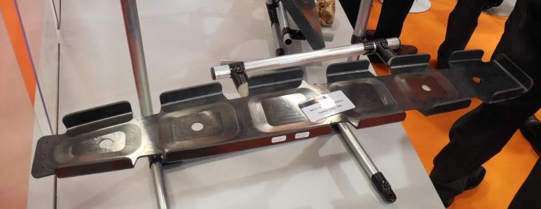
66 xample beam profile coupons 66 Spindle ram coupons comparison of steel, cast iron, CFRP plates assembly and profile by winding F models derived from the previous cases separation of elements for damping layers Cast iron Welded steel CFRP plates Filament winding F_1 [Hz] xp_1 [Hz] F_2 [Hz] xperiment to F deviation in bending bellow 1% xp_2 [Hz]


![f F [Hz] f F/XP [%] 1 492 468-4,9 1 st bending](/docs-images/83/88390783/images/67-4.jpg "2 493 596 2,9 3 784 715-8,8 4 922 921 -,1 5 1")
67 xample - hybrid spindle ram 67 Modelling of hybrid spindle ram and its composite reinforcement Combination of carbon/epoxy layers from PITCH and PN fibres, 1 integrated damping layer Solid shell model with element stacking For bending modes deviation between F and experiment bellow 5% For other modes deviation up to 2% and more Mode [-] f XP [Hz] f F [Hz] f F/XP [%] ,9 1 st bending , , , ,9 2 nd bending #1 #2 #3 #4


68 68 xample material degradation Crash absorbers simulation ability of progressive damaging of fibre composites to transform kinetic energy into the deformation energy in the safety element ii v bezpečnostním členu
69 69 Simulations of progressive damaging progressive damage implemented by failure criteria (Chang-Chang) element stiffness degradation in respect to achieving criterion after the set level of degradation element removal Chang-Chang failure criterion fibre failure in tension stiffness change of element for f ft =1 fibre failure in compression stiffness change of element for f fc =1 matrix failure in tension stiffness change of element for f mt =1 matrix failure in compression stiffness change of element for f mc =1 xample material degradation 1,, ˆ ˆ s s where S X f L T ft 11 = 22 = = ν = ν 21 =, ˆ 2 11 C fc X f s, ˆ ˆ L T mt S Y f s s. ˆ ˆ ˆ L C T C T mc S Y S Y S f s s s 11 = ν = ν 21 =, 22 = = ν 21 =, 22 = = ν = ν 21 =


70 7 xample material degradation Simulations of progressive damaging LS-yna: shell element with 1 element per the coupon thickness good match with experimental behaviour


71 xample material degradation 71 Simulations of progressive damaging


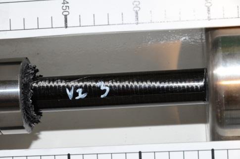
72 72 xample adhesive joints of components Simulation of adhesive joint failure in composite shafts with bonded metal endings prediction of the joint degradation cohesive elements damage initiation damage growth after the determined degradation element removal demonstration from the development of composite shafts for the machine tool industry dhesive joint model amage initiation and growth


73 73 xample adhesive joints of components Simulation of adhesive joint failure in composite shafts with bonded metal endings prediction of the joint degradation cohesive elements damage initiation damage growth after the determined degradation element removal demonstration from the development of composite shafts for the machine tool industry xperimental testing loading of shafts in torsion F model of the shaft ending green metal ending blue composite shaft

74 74 xample adhesive joints of components Simulation of adhesive joint failure in composite shafts with bonded metal endings Finite element simulation in comparison with experimental behaviour Comparison of reaction moment and rotation acceptable prediction of maximal loading moment


75 xample sandwich panels 75 Sandwich structures + low-weight design + high bending stiffness + high natural frequencies - low compressive strength - difficulty when joining 5 4 s [MPa] 3 2 1,2,4,6,8 [-]
76 xample sandwich panels 76 Necessary to include the effect of transverse shearing F due to transverse shearing, the normal to the reference surface rotates shell element cannot behave in this way with some exceptions (sandwich logic, balance of energy) nsys: Shell91 former element for sandwich simulations nowadays Shell181,281 - elements model the transverseshear deflection using an energy-equivalence method
77 xample sandwich panels 77 pproaches for F modelling of sandwich panels Shell elements - generally care must be taken as the approach of using 1 shell element for the sandwich structure might work only for specified shells in one F solver, but not in other solver - problematic behaviour of the core with larger compliance (stiffness is lower by 3 orders in comparison with skins does not meet the conditions for shells) Solid elements - core and skins modelled by solid elements, or solid-shell elements - might be problematic for composite skins Combination of solid and shell elements - core modelled by solid elements - skins modelled by shell or solid shell elements
78 xample sandwich panels models shell99 skins, solid95 core Comparison of 3point bending test deflection of the beam Skin Core Weight [kg] Mid Span eflection [mm] F results [mm] C/ C/ Roh71 c=3mm Roh71 c=5mm C/ Roh11 c=3mm, C/ Roh11 c=5mm *.5.44* C/ Roh11 c=5mm *.35.32* C/ l25 c=5mm Steel lporas23 c=5mm *.8.7* Steel lporas23 c=3mm *.13.* Steel l25 c=5mm *.8.6* C/ L honeycomb core,

![modal analysis ifference between FM and experiment bellow 15% for the first bending frequency 3mm C/, 3mm PMI 3mm C/, 5mm PMI Mód f exp [Hz] f mkp1 [Hz] f mkp2 [Hz] f](/docs-images/83/88390783/images/79-1.jpg "exp [Hz] f mkp1 [Hz] f mkp2 [Hz] 1 415.7 373.4 376.4 529.2 469.9 475.3 2 539.8 539.8 543.9 747.9 675.4 683 3 713.5 618.7 624.7 851.6 739.7 749.2 4 764 66.1 668.5 924.")
79 79 xample sandwich panels F model 1: nsys skins: Shell99, 7 layers core: Solid95 Skins are at the top (bottom) surface of the solid core; with offset from the midsurface Nodes of the shell skins are shared with the nodes of the solid core surface F model 2: baqus skin: S4R core: C38i *Tie constraint between skin and shell xperimental modal analysis ifference between FM and experiment bellow 15% for the first bending frequency 3mm C/, 3mm PMI 3mm C/, 5mm PMI Mód f exp [Hz] f mkp1 [Hz] f mkp2 [Hz] f exp [Hz] f mkp1 [Hz] f mkp2 [Hz]
80 8 Thank you for your attention! Contact
FINITE ELEMENT AND EXPERIMENTAL STUDY OF NOVEL CONCEPT OF 3D FIBRE CELL STRUCTURE
 FINITE ELEMENT AND EXPERIMENTAL STUDY OF NOVEL CONCEPT OF 3D FIBRE CELL STRUCTURE M. Růžička, V. Kulíšek 2, J. Had, O. Prejzek Department of Mechanics, Biomechanics and Mechatronics, Faculty of Mechanical
Computational Analysis for Composites
 Computational Analysis for Composites Professor Johann Sienz and Dr. Tony Murmu Swansea University July, 011 The topics covered include: OUTLINE Overview of composites and their applications Micromechanics
QUESTION BANK Composite Materials
 QUESTION BANK Composite Materials 1. Define composite material. 2. What is the need for composite material? 3. Mention important characterits of composite material 4. Give examples for fiber material 5.
INTERNATIONAL JOURNAL OF APPLIED ENGINEERING RESEARCH, DINDIGUL Volume 2, No 1, 2011
 Interlaminar failure analysis of FRP cross ply laminate with elliptical cutout Venkateswara Rao.S 1, Sd. Abdul Kalam 1, Srilakshmi.S 1, Bala Krishna Murthy.V 2 1 Mechanical Engineering Department, P. V.
TABLE OF CONTENTS. Mechanics of Composite Materials, Second Edition Autar K Kaw University of South Florida, Tampa, USA
 Mechanics of Composite Materials, Second Edition Autar K Kaw University of South Florida, Tampa, USA TABLE OF CONTENTS 1. INTRODUCTION TO COMPOSITE MATERIALS 1.1 Introduction... 1.2 Classification... 1.2.1
Hygrothermal stresses in laminates
 Hygrothermal stresses in laminates Changing environment conditions (temperature and moisture) have an important effect on the properties which are matrix dominated. Change in temperaturet and moisture
Composite models 30 and 131: Ply types 0 and 8 calibration
 Model calibration Composite Bi-Phase models 30 and 3 for elastic, damage and failure PAM-CRASH material model 30 is for solid and 3 for multi-layered shell elements. Within these models different ply types
Lecture 8. Stress Strain in Multi-dimension
 Lecture 8. Stress Strain in Multi-dimension Module. General Field Equations General Field Equations [] Equilibrium Equations in Elastic bodies xx x y z yx zx f x 0, etc [2] Kinematics xx u x x,etc. [3]
Fracture Mechanics, Damage and Fatigue: Composites
 University of Liège Aerospace & Mechanical Engineering Fracture Mechanics, Damage and Fatigue: Composites Ludovic Noels Computational & Multiscale Mechanics of Materials CM3 http://www.ltas-cm3.ulg.ac.be/
Open-hole compressive strength prediction of CFRP composite laminates
 Open-hole compressive strength prediction of CFRP composite laminates O. İnal 1, A. Ataş 2,* 1 Department of Mechanical Engineering, Balikesir University, Balikesir, 10145, Turkey, inal@balikesir.edu.tr
Module III - Macro-mechanics of Lamina. Lecture 23. Macro-Mechanics of Lamina
 Module III - Macro-mechanics of Lamina Lecture 23 Macro-Mechanics of Lamina For better understanding of the macromechanics of lamina, the knowledge of the material properties in essential. Therefore, the
VALIDATION of CoDA SOFTWARE for COMPOSITES SYNTHESIS AND PRELIMINARY DESIGN (or GETTING COMPOSITES USED - PART 2 )
") VALIDATION of CoDA SOFTWARE for COMPOSITES SYNTHESIS AND PRELIMINARY DESIGN (or GETTING COMPOSITES USED - PART 2 ) Graham D Sims and William R Broughton Composites Design Data and Methods, Centre for Materials
VALIDATION of CoDA SOFTWARE for COMPOSITES SYNTHESIS AND PRELIMINARY DESIGN (or GETTING COMPOSITES USED - PART 2 ) Graham D Sims and William R Broughton Composites Design Data and Methods, Centre for Materials
Tensile behaviour of anti-symmetric CFRP composite
 Available online at www.sciencedirect.com Procedia Engineering 1 (211) 1865 187 ICM11 Tensile behaviour of anti-symmetric CFRP composite K. J. Wong a,b, *, X. J. Gong a, S. Aivazzadeh a, M. N. Tamin b
Calibration and Experimental Validation of LS-DYNA Composite Material Models by Multi Objective Optimization Techniques
 9 th International LS-DYNA Users Conference Optimization Calibration and Experimental Validation of LS-DYNA Composite Material Models by Multi Objective Optimization Techniques Stefano Magistrali*, Marco
An overview of Carbon Fiber modeling in LS-DYNA. John Zhao October 23 th 2017
 An overview of Carbon Fiber modeling in LS-DYNA John Zhao zhao@lstc.com October 23 th 2017 Outline Manufacturing of Carbon Fiber Compression molding *MAT_277 & 278 *MAT_293 *MAT_249 Resin transform molding
Influence of the filament winding process variables on the mechanical behavior of a composite pressure vessel
 Influence of the filament winding process variables on the mechanical behavior of a composite pressure vessel G. Vargas 1 & A. Miravete 2 1 Universidad Pontificia Bolivariana, Facultad de Ingeniería Mecánica,
A Study on the Tube of Integral Propeller Shaft for the Rear-wheel Drive Automobile Using Carbon Composite Fiber
 A Study on the Tube of Integral Propeller Shaft for the Rear-wheel Drive Automobile Using Carbon Composite Fiber Kibong Han Mechatronics Department, Jungwon University, 85 Munmu-ro, Goesan-gun, South Korea.
Mechanical Properties of Materials
 Mechanical Properties of Materials Strains Material Model Stresses Learning objectives Understand the qualitative and quantitative description of mechanical properties of materials. Learn the logic of
Module 4: Behaviour of a Laminae-II. Learning Unit 1: M1. M4.1 Mechanics of Composites. M4.1.1 Introduction to Mechanics of Composites
 Module 4: Behaviour of a Laminae-II Learning Unit 1: M1 M4.1 Mechanics of Composites M4.1.1 Introduction to Mechanics of Composites The relation between ply uniaxial strengths and constituent properties
NUMERICAL FEM ANALYSIS FOR THE PART OF COMPOSITE HELICOPTER ROTOR BLADE
 Journal of KONES Powertrain and Transport, Vol. 19, No. 1 2012 NUMERICAL FEM ANALYSIS FOR THE PART OF COMPOSITE HELICOPTER ROTOR BLADE Hubert D bski Lublin University of Technology, Department of Machine
Effects of Resin and Fabric Structure
 Fatigue of Wind Blade Laminates: Effects of Resin and Fabric Structure Details David Miller, Daniel D. Samborsky and John F. Mandell Montana State t University it MCARE 2012 Outline Overview of MSU Fatigue
PRELIMINARY PREDICTION OF SPECIMEN PROPERTIES CLT and 1 st order FEM analyses
 OPTIMAT BLADES Page 1 of 24 PRELIMINARY PREDICTION OF SPECIMEN PROPERTIES CLT and 1 st order FEM analyses first issue Peter Joosse CHANGE RECORD Issue/revision date pages Summary of changes draft 24-10-02
Modelling the nonlinear shear stress-strain response of glass fibrereinforced composites. Part II: Model development and finite element simulations
 Modelling the nonlinear shear stress-strain response of glass fibrereinforced composites. Part II: Model development and finite element simulations W. Van Paepegem *, I. De Baere and J. Degrieck Ghent
Impact and Crash Modeling of Composite Structures: A Challenge for Damage Mechanics
 Impact and Crash Modeling of Composite Structures: A Challenge for Damage Mechanics Dr. A. Johnson DLR Dr. A. K. Pickett ESI GmbH EURO-PAM 99 Impact and Crash Modelling of Composite Structures: A Challenge
Fracture Behaviour of FRP Cross-Ply Laminate With Embedded Delamination Subjected To Transverse Load
 Fracture Behaviour of FRP Cross-Ply Laminate With Embedded Delamination Subjected To Transverse Load Sriram Chintapalli 1, S.Srilakshmi 1 1 Dept. of Mech. Engg., P. V. P. Siddhartha Institute of Technology.
Comparison of Ply-wise Stress-Strain results for graphite/epoxy laminated plate subjected to in-plane normal loads using CLT and ANSYS ACP PrepPost
 Comparison of Ply-wise Stress-Strain results for graphite/epoxy laminated plate subjected to in-plane normal loads using CLT and ANSYS ACP PrepPost 1 Mihir A. Mehta, 2 Satyen D. Ramani 1 PG Student, Department
MODELING OF THE BEHAVIOR OF WOVEN LAMINATED COMPOSITES UNTIL RUPTURE
 MODELING OF THE BEHAVIOR OF WOVEN LAMINATED COMPOSITES UNTIL RUPTURE Jean Paul Charles, Christian Hochard,3, Pierre Antoine Aubourg,3 Eurocopter, 375 Marignane cedex, France Unimeca, 6 rue J. Curie, 3453
IJSER 1. INTRODUCTION. M.Elhadary
 1591 A new failure criterion for GRP composite materials subjected to in-phase and out-of-phase biaxial fatigue loading under different stress ratios M.Elhadary Abstract this studying the fatigue behavior
Finite element modelling of infinitely wide Angle-ply FRP. laminates
 www.ijaser.com 2012 by the authors Licensee IJASER- Under Creative Commons License 3.0 editorial@ijaser.com Research article ISSN 2277 9442 Finite element modelling of infinitely wide Angle-ply FRP laminates
Predicting Failure of Multiangle Composite Laminates
 Predicting Failure of Multiangle Composite Laminates Preliminary discussion (not in textbook): Micromechanics failure analyses vs Macromechanics failure analyses Fiber Architecture of Some Common Composite
Analysis and Optimization of a Hybrid Fan Blade
 Analysis and Optimization of a Hybrid Fan Blade Permas Users Conference 27.04.06 28.04.06 Strassbourg DLR German Aerospace Center, Stuttgart Institute of Structures and Design J. Ehrmanntraut, F. Kocian,
Outline. Tensile-Test Specimen and Machine. Stress-Strain Curve. Review of Mechanical Properties. Mechanical Behaviour
 Tensile-Test Specimen and Machine Review of Mechanical Properties Outline Tensile test True stress - true strain (flow curve) mechanical properties: - Resilience - Ductility - Toughness - Hardness A standard
Micro-meso draping modelling of non-crimp fabrics
 Micro-meso draping modelling of non-crimp fabrics Oleksandr Vorobiov 1, Dr. Th. Bischoff 1, Dr. A. Tulke 1 1 FTA Forschungsgesellschaft für Textiltechnik mbh 1 Introduction Non-crimp fabrics (NCFs) are
Crash and Impact Simulation of Composite Structures by Using CAE Process Chain
 Crash and Impact Simulation of Composite Structures by Using CAE Process Chain Madhukar Chatiri 1, Thorsten Schütz 2, Anton Matzenmiller 3, Ulrich Stelzmann 1 1 CADFEM GmbH, Grafing/Munich, Germany, mchatiri@cadfem.de
A RESEARCH ON NONLINEAR STABILITY AND FAILURE OF THIN- WALLED COMPOSITE COLUMNS WITH OPEN CROSS-SECTION
 A RESEARCH ON NONLINEAR STABILITY AND FAILURE OF THIN- WALLED COMPOSITE COLUMNS WITH OPEN CROSS-SECTION H. Debski a*, J. Bienias b, P. Jakubczak b a Faculty of Mechanical Engineering, Department of Machine
FINITE ELEMENT ANALYSIS OF COMPOSITE MATERIALS
 FINITE ELEMENT ANALYSIS OF COMPOSITE MATERIALS Ever J. Barbero Department of Mechanical and Aerospace Engineering West Virginia University USA CRC Press Taylor &.Francis Group Boca Raton London New York
SOME RESEARCH ON FINITE ELEMENT ANALYSIS OF COMPOSITE MATERIALS
 Mechanical Testing and Diagnosis ISSN 2247 9635, 2012 (II), Volume 3, 79-85 SOME RESEARCH ON FINITE ELEMENT ANALYSIS OF COMPOSITE MATERIALS Valeriu DULGHERU, Viorel BOSTAN, Marin GUŢU Technical University
Multi Disciplinary Delamination Studies In Frp Composites Using 3d Finite Element Analysis Mohan Rentala
 Multi Disciplinary Delamination Studies In Frp Composites Using 3d Finite Element Analysis Mohan Rentala Abstract: FRP laminated composites have been extensively used in Aerospace and allied industries
ISSN: ISO 9001:2008 Certified International Journal of Engineering Science and Innovative Technology (IJESIT) Volume 2, Issue 4, July 2013
 Volume 2, Issue 4, July 2013") Delamination Studies in Fibre-Reinforced Polymer Composites K.Kantha Rao, Dr P. Shailesh, K. Vijay Kumar 1 Associate Professor, Narasimha Reddy Engineering College Hyderabad. 2 Professor, St. Peter s Engineering
Delamination Studies in Fibre-Reinforced Polymer Composites K.Kantha Rao, Dr P. Shailesh, K. Vijay Kumar 1 Associate Professor, Narasimha Reddy Engineering College Hyderabad. 2 Professor, St. Peter s Engineering
CHEM-C2410: Materials Science from Microstructures to Properties Composites: basic principles
 CHEM-C2410: Materials Science from Microstructures to Properties Composites: basic principles Mark Hughes 14 th March 2017 Today s learning outcomes To understand the role of reinforcement, matrix and
Passive Damping Characteristics of Carbon Epoxy Composite Plates
 Journal of Materials Science and Engineering A 6 (-) 35-4 doi:.765/6-63/6.-.5 D DAVID PUBLISHING Passive Damping Characteristics of Carbon Epoxy Composite Plates Dileep Kumar K * and V V Subba Rao Faculty
five Mechanics of Materials 1 ARCHITECTURAL STRUCTURES: FORM, BEHAVIOR, AND DESIGN DR. ANNE NICHOLS SUMMER 2017 lecture
 ARCHITECTURAL STRUCTURES: FORM, BEHAVIOR, AND DESIGN DR. ANNE NICHOLS SUMMER 2017 lecture five mechanics www.carttalk.com of materials Mechanics of Materials 1 Mechanics of Materials MECHANICS MATERIALS
Most of the material in this package is based on a recently published book. This is:
 Mechanics of Composite Materials Version 2.1 Bill Clyne, University of Cambridge Boban Tanovic, MATTER Assumed Pre-knowledge It is assumed that the student is familiar with simple concepts of mechanical
DAMAGE MECHANICS MODEL FOR OFF-AXIS FATIGUE BEHAVIOR OF UNIDIRECTIONAL CARBON FIBER-REINFORCED COMPOSITES AT ROOM AND HIGH TEMPERATURES
 DAMAGE MECHANICS MODEL FOR OFF-AXIS FATIGUE BEHAVIOR OF UNIDIRECTIONAL CARBON FIBER-REINFORCED COMPOSITES AT ROOM AND HIGH TEMPERATURES M. Kawai Institute of Engineering Mechanics University of Tsukuba,
Crashworthiness of composite structures: Experiment and Simulation
 Crashworthiness of composite structures: Experiment and Simulation Francesco Deleo, Bonnie Wade and Prof. Paolo Feraboli (UW) Dr. Mostafa Rassaian (Boeing R&T) JAMS 2010 The Joint Advanced Materials and
COMPUTER AIDED DESIGN IN CASE OF THE LAMINATED COMPOSITE MATERIALS
 6 th International Conference Computational Mechanics and Virtual Engineering COMEC 15 15-16 October 15, Braşov, Romania COMPUER AIDED DESIGN IN CASE OF HE LAMINAED COMPOSIE MAERIALS Camelia Cerbu ransilvania
Prediction of Elastic Constants on 3D Four-directional Braided
 Prediction of Elastic Constants on 3D Four-directional Braided Composites Prediction of Elastic Constants on 3D Four-directional Braided Composites Liang Dao Zhou 1,2,* and Zhuo Zhuang 1 1 School of Aerospace,
An integrated approach to the design of high performance carbon fibre reinforced risers - from micro to macro - scale
 An integrated approach to the design of high performance carbon fibre reinforced risers - from micro to macro - scale Angelos Mintzas 1, Steve Hatton 1, Sarinova Simandjuntak 2, Andrew Little 2, Zhongyi
Bending of Simply Supported Isotropic and Composite Laminate Plates
 Bending of Simply Supported Isotropic and Composite Laminate Plates Ernesto Gutierrez-Miravete 1 Isotropic Plates Consider simply a supported rectangular plate of isotropic material (length a, width b,
UNIVERSITY OF SASKATCHEWAN ME MECHANICS OF MATERIALS I FINAL EXAM DECEMBER 13, 2008 Professor A. Dolovich
 UNIVERSITY OF SASKATCHEWAN ME 313.3 MECHANICS OF MATERIALS I FINAL EXAM DECEMBER 13, 2008 Professor A. Dolovich A CLOSED BOOK EXAMINATION TIME: 3 HOURS For Marker s Use Only LAST NAME (printed): FIRST
ME 7502 Lecture 2 Effective Properties of Particulate and Unidirectional Composites
 ME 75 Lecture Effective Properties of Particulate and Unidirectional Composites Concepts from Elasticit Theor Statistical Homogeneit, Representative Volume Element, Composite Material Effective Stress-
NUMERICAL SIMULATION OF DAMAGE IN THERMOPLASTIC COMPOSITE MATERIALS
 5 th European LS-DYNA Users Conference Composites NUMERICAL SIMULATION OF DAMAGE IN THERMOPLASTIC COMPOSITE MATERIALS Kevin Brown 1, Richard Brooks, Nicholas Warrior School of Mechanical, Materials and
[5] Stress and Strain
![[5] Stress and Strain](/thumbs/95/123344550.jpg "[5] Stress and Strain") [5] Stress and Strain Page 1 of 34 [5] Stress and Strain [5.1] Internal Stress of Solids [5.2] Design of Simple Connections (will not be covered in class) [5.3] Deformation and Strain [5.4] Hooke s Law
[5] Stress and Strain Page 1 of 34 [5] Stress and Strain [5.1] Internal Stress of Solids [5.2] Design of Simple Connections (will not be covered in class) [5.3] Deformation and Strain [5.4] Hooke s Law
A HIGHER-ORDER BEAM THEORY FOR COMPOSITE BOX BEAMS
 A HIGHER-ORDER BEAM THEORY FOR COMPOSITE BOX BEAMS A. Kroker, W. Becker TU Darmstadt, Department of Mechanical Engineering, Chair of Structural Mechanics Hochschulstr. 1, D-64289 Darmstadt, Germany kroker@mechanik.tu-darmstadt.de,
Analysis of Composite Pressure Vessels
 Analysis of Composite Pressure Vessels Reza Mohammadzadeh Gheshlaghi 1 Mohammad Hassan Hojjati Hamid Reza Mohammadi Daniali 3 1 Engineering Research Centre, Tabriz, Iran,3 Department of Mechanical Engineering,
MECHANICAL FAILURE OF A COMPOSITE HELICOPTER STRUCTURE UNDER STATIC LOADING
 MECHANICAL FAILURE OF A COMPOSITE HELICOPTER STRUCTURE UNDER STATIC LOADING Steven Roy, Larry Lessard Dept. of Mechanical Engineering, McGill University, Montreal, Québec, Canada ABSTRACT The design and
Stress, Strain Stress strain relationships for different types of materials Stress strain relationships for a unidirectional/bidirectional lamina
 Chapter 2 Macromechanical Analysis of a Lamina Stress, Strain Stress strain relationships for different types of materials Stress strain relationships for a unidirectional/bidirectional lamina Islamic
Mechanical Behavior of Circular Composite Springs with Extended Flat Contact Surfaces
 Mechanical Behavior of Circular Composite Springs with Extended Flat Contact Surfaces Ping-Cheung Tse epartment of Mechanical Engineering, The Hong Kong Polytechnic University, Hunghom, Kowloon, Hong Kong
MATERIAL MECHANICS, SE2126 COMPUTER LAB 4 MICRO MECHANICS. E E v E E E E E v E E + + = m f f. f f
 MATRIAL MCHANICS, S226 COMPUTR LAB 4 MICRO MCHANICS 2 2 2 f m f f m T m f m f f m v v + + = + PART A SPHRICAL PARTICL INCLUSION Consider a solid granular material, a so called particle composite, shown
Project MMS13 Task 5 Report No 3 (M6/D3)
") Project MMS13 Task 5 Report No 3 (M6/D3) Material Data Requirements and Recommended Test Methods for the Predictive Modelling of Defect Criticality in Composite Material Systems M R L Gower and G D Sims
Project MMS13 Task 5 Report No 3 (M6/D3) Material Data Requirements and Recommended Test Methods for the Predictive Modelling of Defect Criticality in Composite Material Systems M R L Gower and G D Sims
PREDICTION OF OUT-OF-PLANE FAILURE MODES IN CFRP
 PREDICTION OF OUT-OF-PLANE FAILURE MODES IN CFRP R. R. Pinto 1, P. P. Camanho 2 1 INEGI - Instituto de Engenharia Mecanica e Gestao Industrial, Rua Dr. Roberto Frias, 4200-465, Porto, Portugal 2 DEMec,
Assessment Methods of Mechanical Properties of Composite Materials
 Mechanics and Mechanical Engineering Vol. 21, No. 4 (2017) 1005 1018 c Lodz University of Technology Assessment Methods of Mechanical Properties of Composite Materials Monika Kamocka Radoslaw J. Mania
Parameter Design of High Speed Coupling for 6 MW Wind Turbine Considering Torsional Vibration
 Parameter Design of High Speed Coupling for 6 MW Wind Turbine Considering Torsional Vibration JongHun Kang 1, Junwoo Bae 2, Seungkeun Jeong 3, SooKeun Park 4 and Hyoung Woo Lee 1 # 1 Department of Mechatronics
Composite Laminate Modeling
 omposite Laminate Modeling White Paper for Femap and NX Nastran Users Venkata Bheemreddy, Ph.D., Senior Staff Mechanical Engineer Adrian Jensen, PE, Senior Staff Mechanical Engineer WHAT THIS WHITE PAPER
SCALING EFFECTS IN THE LOW VELOCITY IMPACT RESPONSE OF FIBRE METAL
 SCALING EFFECTS IN THE LOW VELOCITY IMPACT RESPONSE OF FIBRE METAL LAMINATES J. G. Carrillo 1, S. McKown 1, M. Mujib 1 and W. J. Cantwell 1. R. Day 2 1 Department of Engineering, University of Liverpool,
Non-conventional Glass fiber NCF composites with thermoset and thermoplastic matrices. F Talence, France Le Cheylard, France
 20 th International Conference on Composite Materials Copenhagen, 19-24th July 2015 Non-conventional Glass fiber NCF composites with thermoset and thermoplastic matrices. Thierry Lorriot 1, Jalal El Yagoubi
Effect of Specimen Dimensions on Flexural Modulus in a 3-Point Bending Test
 Effect of Specimen Dimensions on Flexural Modulus in a 3-Point Bending Test M. Praveen Kumar 1 and V. Balakrishna Murthy 2* 1 Mechanical Engineering Department, P.V.P. Siddhartha Institute of Technology,
MECHANICS OF MATERIALS
 CHATR Stress MCHANICS OF MATRIALS and Strain Axial Loading Stress & Strain: Axial Loading Suitability of a structure or machine may depend on the deformations in the structure as well as the stresses induced
Table of Contents. Preface...xvii. Part 1. Level
 Preface...xvii Part 1. Level 1... 1 Chapter 1. The Basics of Linear Elastic Behavior... 3 1.1. Cohesion forces... 4 1.2. The notion of stress... 6 1.2.1. Definition... 6 1.2.2. Graphical representation...
GB/T / ISO 527-1:1993
 Translated English of Chinese Standard: GB/T1040.1-2006 www.chinesestandard.net Sales@ChineseStandard.net GB NATIONAL STANDARD OF THE PEOPLE S REPUBLIC OF CHINA ICS 83.080.01 G 31 GB/T 1040.1-2006 / ISO
Multiscale Approach to Damage Analysis of Laminated Composite Structures
 Multiscale Approach to Damage Analysis of Laminated Composite Structures D. Ivančević and I. Smojver Department of Aeronautical Engineering, Faculty of Mechanical Engineering and Naval Architecture, University
EXPERIMENTAL AND NUMERICAL STUDY OF THE ENERGY ABSORPTION CAPACITY OF PULTRUDED COMPOSITE TUBES
 EXPERIMENTAL AND NUMERICAL STUDY OF THE ENERGY ABSORPTION CAPACITY OF PULTRUDED COMPOSITE TUBES D. Kakogiannis 1, D. Van Hemelrijck 1, J. Wastiels 1, S. Palanivelu 2, W. Van Paepegem 2, K. De Wolf 3, J.
Review Lecture. AE1108-II: Aerospace Mechanics of Materials. Dr. Calvin Rans Dr. Sofia Teixeira De Freitas
 Review Lecture AE1108-II: Aerospace Mechanics of Materials Dr. Calvin Rans Dr. Sofia Teixeira De Freitas Aerospace Structures & Materials Faculty of Aerospace Engineering Analysis of an Engineering System
THREE DIMENSIONAL STRESS ANALYSIS OF THE T BOLT JOINT
 THREE DIMENSIONAL STRESS ANALYSIS OF THE T BOLT JOINT Víctor Martínez 1, Alfredo Güemes 2, Norbert Blanco 1, Josep Costa 1 1 Escola Politècnica Superior. Universitat de Girona. Girona, Spain (17071) 2
Composite Damage Material Modeling for Crash Simulation: MAT54 & the Efforts of the CMH-17 Numerical Round Robin
 Composite Damage Material Modeling for Crash Simulation: MAT54 & the Efforts of the CMH-17 Numerical Round Robin 2014 Technical Review Bonnie Wade (UW) Prof. Paolo Feraboli AMTAS (JAMS) Crashworthiness
Numerical Evaluation of Fracture in Woven Composites by Using Properties of Unidirectional Type for modelling
 J. Basic. Appl. Sci. Res., 2(12)13202-13209, 2012 2012, TextRoad Publication ISSN 2090-4304 Journal of Basic and Applied Scientific Research www.textroad.com Numerical Evaluation of Fracture in Woven Composites
THE MUTUAL EFFECTS OF SHEAR AND TRANSVERSE DAMAGE IN POLYMERIC COMPOSITES
 THE 19 TH INTERNATIONAL CONFERENCE ON COMPOSITE MATERIALS THE MUTUAL EFFECTS OF SHEAR AND TRANSVERSE DAMAGE IN POLYMERIC COMPOSITES L.V. Smith 1 *, M. Salavatian 1 1 School of Mechanical and Materials
DESIGNING A FLEXIBLE BELLOWS COUPLING MADE FROM COMPOSITE MATERIALS USING NUMERICAL SIMULATIONS SVOČ FST 2018
 DESIGNING A FLEXIBLE BELLOWS COUPLING MADE FROM COMPOSITE MATERIALS USING NUMERICAL SIMULATIONS SVOČ FST 2018 Ing. Frantisek Sedlacek, University of West Bohemia, Univerzitni 8, 306 14, Pilsen, Czech Republic
BIAXIAL STRENGTH INVESTIGATION OF CFRP COMPOSITE LAMINATES BY USING CRUCIFORM SPECIMENS
 BIAXIAL STRENGTH INVESTIGATION OF CFRP COMPOSITE LAMINATES BY USING CRUCIFORM SPECIMENS H. Kumazawa and T. Takatoya Airframes and Structures Group, Japan Aerospace Exploration Agency 6-13-1, Ohsawa, Mitaka,
ANALYTICAL SOLUTIONS USING HIGH ORDER COMPOSITE LAMINATE THEORY FOR HONEYCOMB SANDWICH PLATES WITH VISCOELASTIC FREQUENCY DEPENDENT DAMPING
 Clemson University TigerPrints All Theses Theses 8-11 ANALYTICAL SOLUTIONS USING HIGH ORDER COMPOSITE LAMINATE THEORY FOR HONEYCOMB SANDWICH PLATES WITH VISCOELASTIC FREQUENCY DEPENDENT DAMPING Nan Shan
Finite element analysis of drilled holes in uni-directional composite laminates using failure theories
 American Journal of Science and Technology 2014; 1(3): 101-105 Published online May 30, 2014 (http://www.aascit.org/journal/ajst) Finite element analysis of drilled holes in uni-directional composite laminates
Homework No. 1 MAE/CE 459/559 John A. Gilbert, Ph.D. Fall 2004
 Homework No. 1 MAE/CE 459/559 John A. Gilbert, Ph.D. 1. A beam is loaded as shown. The dimensions of the cross section appear in the insert. the figure. Draw a complete free body diagram showing an equivalent
Strength of GRP-laminates with multiple fragment damages
 Strength of GRP-laminates with multiple fragment damages S. Kazemahvazi, J. Kiele, D. Zenkert Kungliga Tekniska Högskolan, KTH 100 44 Stockholm, Sweden sohrabk@kth.se SUMMARY The strength of glass fibre
EMA 3702 Mechanics & Materials Science (Mechanics of Materials) Chapter 2 Stress & Strain - Axial Loading
 Chapter 2 Stress & Strain - Axial Loading") MA 3702 Mechanics & Materials Science (Mechanics of Materials) Chapter 2 Stress & Strain - Axial Loading MA 3702 Mechanics & Materials Science Zhe Cheng (2018) 2 Stress & Strain - Axial Loading Statics
MA 3702 Mechanics & Materials Science (Mechanics of Materials) Chapter 2 Stress & Strain - Axial Loading MA 3702 Mechanics & Materials Science Zhe Cheng (2018) 2 Stress & Strain - Axial Loading Statics
Constitutive Equations (Linear Elasticity)
") Constitutive quations (Linear lasticity) quations that characterize the physical properties of the material of a system are called constitutive equations. It is possible to find the applied stresses knowing
Constitutive quations (Linear lasticity) quations that characterize the physical properties of the material of a system are called constitutive equations. It is possible to find the applied stresses knowing
Mechanics of Materials Primer
 Mechanics of Materials rimer Notation: A = area (net = with holes, bearing = in contact, etc...) b = total width of material at a horizontal section d = diameter of a hole D = symbol for diameter E = modulus
DRAPING SIMULATION. Recent achievements and future trends. Dr. Sylvain Bel LGCIE University Lyon 1
 DRAPING SIMULATION Recent achievements and future trends 1 Dr. Sylvain Bel LGCIE University Lyon 1 2 DRAPING SIMULATION Why? How? What? DRAPING SIMULATION WHY? Clamps Punch Fabric Die 1 2 Resin 3 4 Fig.
Smart Materials, Adaptive Structures, and Intelligent Mechanical Systems
 Smart Materials, Adaptive Structures, and Intelligent Mechanical Systems Bishakh Bhattacharya & Nachiketa Tiwari Indian Institute of Technology Kanpur Lecture 19 Analysis of an Orthotropic Ply References
The Accuracy of Characteristic Length Method on Failure Load Prediction of Composite Pinned Joints
 , June 30 - July 2, 2010, London, U.K. The Accuracy of Characteristic Length Method on Failure Load Prediction of Composite Pinned Joints O. Aluko, and Q. Mazumder Abstract An analytical model was developed
Composite FEM Lab-work
 Composite FEM Lab-work You may perform these exercises in groups of max 2 persons. You may also between exercise 5 and 6. Be critical on the results obtained! Exercise 1. Open the file exercise1.inp in
Use Hooke s Law (as it applies in the uniaxial direction),
,") 0.6 STRSS-STRAIN RLATIONSHIP Use the principle of superposition Use Poisson s ratio, v lateral longitudinal Use Hooke s Law (as it applies in the uniaxial direction), x x v y z, y y vx z, z z vx y Copyright
0.6 STRSS-STRAIN RLATIONSHIP Use the principle of superposition Use Poisson s ratio, v lateral longitudinal Use Hooke s Law (as it applies in the uniaxial direction), x x v y z, y y vx z, z z vx y Copyright
A STRUCTURE DESIGN OF CFRP REAR PRESSURE BULKHEAD WITHOUT STIFFENERS
 Xi an, 2-25 th August 217 A STRUCTURE DESIGN OF CFRP REAR PRESSURE BULKHEAD WITHOUT STIFFENERS LI Zhongyang 1, LI Dong 2 Mailbox72-35, Yanliang District, Xian, China, Email: zhongyangli@live.com Keywords:
ANALYSIS OF LOAD FLOW AND STRESS CONCENTRATIONS IN TEXTILE COMPOSITES
 16 TH INTERNATIONAL CONFERENCE ON COMPOSITE MATERIALS ANALYSIS OF LOAD FLOW AND STRESS CONCENTRATIONS IN TEXTILE COMPOSITES Deepak Goyal*, John D. Whitcomb*, Julian Varghese* *Department of Aerospace Engineering,
INCREASING RUPTURE PREDICTABILITY FOR ALUMINUM
 1 INCREASING RUPTURE PREDICTABILITY FOR ALUMINUM Influence of anisotropy Daniel Riemensperger, Adam Opel AG Paul Du Bois, PDB 2 www.opel.com CONTENT Introduction/motivation Isotropic & anisotropic material
FLEXURAL RESPONSE OF FIBER RENFORCED PLASTIC DECKS USING HIGHER-ORDER SHEAR DEFORMABLE PLATE THEORY
 Asia-Pacific Conference on FRP in Structures (APFIS 2007) S.T. Smith (ed) 2007 International Institute for FRP in Construction FLEXURAL RESPONSE OF FIBER RENFORCED PLASTIC DECKS USING HIGHER-ORDER SHEAR
Benchmarking study of steel-composite structures in CAE crash applications. Master s thesis in Applied Mechanics MADELEINE ANDERSSON EMMA LARSSON
 Benchmarking study of steel-composite structures in CAE crash applications Master s thesis in Applied Mechanics MADELEINE ANDERSSON EMMA LARSSON Department of Applied Mechanics CHALMERS UNIVERSITY OF TECHNOLOGY
Coupling of plasticity and damage in glass fibre reinforced polymer composites
 EPJ Web of Conferences 6, 48 1) DOI: 1.151/epjconf/1648 c Owned by the authors, published by EDP Sciences, 1 Coupling of plasticity and damage in glass fibre reinforced polymer composites R. Kvale Joki
PLY LEVEL UNCERTAINTY EFFECTS ON FAILURE OF COMPOSITE
 7th European Workshop on Structural Health Monitoring July 8-11, 2014. La Cité, Nantes, France More Info at Open Access Database www.ndt.net/?id=17206 PLY LEVEL UNCERTAINTY EFFECTS ON FAILURE OF COMPOSITE
Strength Prediction Of Composite Laminate
 Strength Prediction Of Composite te Prof. Yogananda. A 1, Mr. R. Vijayakumar 2 Assistant Professor, Department of Mechanical Engineering, East West Institute of Technology, Bangalore. Research Scholar,
SANDWICH COMPOSITE BEAMS for STRUCTURAL APPLICATIONS
 SANDWICH COMPOSITE BEAMS for STRUCTURAL APPLICATIONS de Aguiar, José M., josemaguiar@gmail.com Faculdade de Tecnologia de São Paulo, FATEC-SP Centro Estadual de Educação Tecnológica Paula Souza. CEETEPS