Prof. A. Meher Prasad. Department of Civil Engineering Indian Institute of Technology Madras
|
|
|
- Lauren Christina Stephens
- 5 years ago
- Views:
Transcription
1 Prof. A. Meher Prasad Department of Civil Engineering Indian Institute of Technology Madras
2 Dynamic - Loads change with time Nonlinear - Loaded beyond Elastic Limit Type Usual Name Dynamic Effects Material Nonlinearity Linear Static Equivalent Static No No Linear Dynamic Response Spectrum Yes No Nonlinear Static Nonlinear Dynamic Pushover Analysis No Yes Time History Yes Yes
3 Overview What is pushover analysis? What are its fundamental techniques? What tools can be used? Common pitfalls in pushover analysis Example of pushover analysis application
4 Why Push-Over Analysis? Static Nonlinear Analysis technique, also known as sequential yield analysis, or simply "push-over" analysis has gained significant importance during the past few years. It is one of the three analysis techniques recommended by FEMA 273/274 and a main component of the Capacity Spectrum Method (ATC-40). Proper application can provide valuable insights into the expected performance of structural systems and components Misuse can lead to an erroneous understanding of the performance characteristics.
5 What is Push-Over Analysis? Push-over analysis is a technique by which a computer model of the building is subjected to a lateral load of a certain shape (i.e., parabolic, inverted triangular or uniform). The intensity of the lateral load is slowly increased and the sequence of cracks, yielding, plastic hinge formations, and failure of various structural components is recorded. Push-over analysis can provide a significant insight into the weak links in seismic performance of a structure.
6 What is Push-Over Analysis? A series of iterations are usually required during which, the structural deficiencies observed in one iteration, are rectified and followed by another. This iterative analysis and design process continues until the design satisfies a pre-established performance criteria. The performance criteria for push-over analysis is generally established as the desired state of the building given a roof-top or spectral displacement amplitude.
7 Objectives of Push-Over Analysis To obtain the maximum shear strength of the structure, V b, and the mechanism of collapse. To evaluate if the structure can achieve the collapse mechanism without exhausting the plastic rotation capacity of the members. To obtain the monotonic displacement and global ductility capacity of the structure. To estimate the concentration of damage and IDI (Interstorey Drift Index) that can be expected during the nonlinear seismic response.
8 Push-over Curve or Capacity Spectrum V/W (Acceleration) Using simple modal analysis equations spectral displacement and roof-top displacement may be converted to each other. High-Strength; High-Stiffness; Brittle Moderate Strength and Stiffness; Ductile Low-Strength; Low-Stiffness; Brittle Roof-top Displacement
9 Design Spectra Representation Ordinary Design Push-Over Analysis - Composite or ADRS Plot V/W (Acceleration) V/W (Acceleration) Constant Period Lines Period DESIGN SPECTRUM Spectral or Roof-top Displacement ELASTIC DEMAND SPECTRUM
10 What Tools Can Be Used? Nonlinear Analysis software with built-in push-over analysis capabilities DRAIN Spread Plasticity IDARC Spread and Point Plasticity SAP2000NL Point Plasticity ETABS Point Plasticity ANSYS Spread Plasticity SAVE Point Plasticity (Public version) Spread Plasticity (Research version) Sequential application of linear analysis software
11 Spread and Point Plasticity 1. Nonlinearity is assumed to be distributed along the length of the plastic hinge. 2. It provides a more accurate representation of the actual non-linear behaviour of the element Length of plastic hinge 1. Plasticity is assumed to be concentrated at the critical locations. In addition to usual moment hinges, there can be axial hinges and shear hinges. 2. Plastification of the section is assumed to occur suddenly, and not gradually or fibre-by-fibre. Plastic Hinge Curvature diagram along the length of the member
12 Establishing the Performance Point No building can be pushed to infinity without failure. Performance point is where the Seismic Capacity and the Seismic Demand curves meet. If the performance point exists and damage state at that point is acceptable, we have a building that satisfies the push-over criterion.
13 ATC-40 Method V/W (Acceleration) T 0 This is an iterative procedure involving several analyses. For each analysis an effective period for an equivalent elastic system and a corresponding elastic displacement are calculated. This displacement is then divided by a damping factor to obtain an estimate of real displacement at that step of analysis. T eff e /B 5% damped elastic spectrum δ e Roof-top Displacement β eff SR SR A V = κβ ln( βeff ) = ln( βeff ) = 1.65
14 ATC-40 Nonlinear Static Procedure 1. Develop the Pushover Curve
15 ATC-40 Nonlinear Static Procedure 2. Convert Pushover Curve to capacity diagram
16 ATC-40 Nonlinear Static Procedure 3. Plot elastic design spectrum in A-D A D format
17 ATC-40 Nonlinear Static Procedure 4. Plot the demand diagram and capacity diagram together Intersection point gives the displacement demand Avoids nonlinear RHA; instead analyse equivalent linear systems
18 ATC-40 Nonlinear Static Procedure 5. Convert displacement demand to roof displacement and component deformation. 6. Compare to limiting values for specified performance goals.
19 Points to be taken care.. 1. Do not underestimate the importance of the loading or displacement shape function. 2. Know your performance objectives before you push the building. 3. If it is not designed, it cannot be pushed. 4. Do not ignore gravity loads. 5. Do not push beyond failure unless otherwise you can model failure. 6. Pay attention to rebar development and lap lengths. 7. Do not ignore shear failure mechanisms 8. P-Delta P effects may be more important than you think. 9. Do not confuse the Push-over with the real earthquake loading. 10. Three-dimensional buildings may require more than a planar push.
20 1. Do not underestimate the importance of the loading shape function. The loading or deformation shape function is selected to represent the predominant dynamic mode shape of the building. It is most common to keep the load shape constant during the push. Loading shape importance increases for tall buildings whose earthquake response is not dominated by a single mode shape. For these buildings, a loading shape function based on the first mode shape may seriously underestimate the seismic demand on the intermediate floor levels.
21 1. Do not underestimate the importance of the loading shape function. Vb/W /H(%) Inverted Triangle Uniform parabola
22 Adapting Load Patterns So called higher mode effects as the load distribution changes Limit base moment increases adapts for maximum shear force Limit base shear increases adapts for maximum bending moment Not apparent from linear analysis
23 2. Know your performance objectives before you push the building. No building can be displaced to infinity without damage. It is of paramount importance to understand the specific performance objectives desired for the building. Performance objectives such as collapse prevention, life safety, or immediate occupancy have to be translated into technical terms such as: (a) a given set of design spectra, and (b) specific limit states acceptable for various structural components A push-over analysis without a clearly defined performance objectives is of little use.
24 BUILDING PERFORMANCE LEVELS Structural Performance Levels and Ranges Nonstructural Performance Levels S-1 Immediate Occupancy S-2 Damage Control S-3 Life Safety S-4 Limited Safety S-5 Collapse Prevention S-6 Not Considered N-A Operational 1-A Operational 2-A NR NR NR NR N-B Immediate Occupancy 1-B Immediate Occupancy 2-B 3-B NR NR NR N-C Life Safety 1-C 2-C 3-C Life Safety 4-C 5-C 6-C N-D Hazards Reduced NR 2-D 3-D 4-D 5-D 6-D N-E Not Considered NR NR 3-E 4-E 5-E Collapse Prevention No rehabilitation Ref: FEMA 356
25 Earthquake Levels (FEMA356) Earthquake levels p t N Approximate N Remarks years years years Serviceability earthquake % Frequent Serviceability earthquake % Occasional Design basis earthquake (DBE) 10% Rare Maximum considered (MCE) earthquake -1 (alternate) 5% % Very rare Maximum considered (MCE) earthquake -2 (alternate) 2% % Extremely rare
26 Performance Objectives (FEMA 356) Earthquake levels Probability of Exceedance in a period Opera- tional Target building performance level Immediate Occupancy Life Safety Collapse Prevention Serviceability earthquake % in 50 years a b c d Serviceability earthquake % in 50 years e f g h Design basis earthquake (DBE) 10% in 50 years i j k l Maximum considered Earthquake (MCE) 2% in 50 years m n Basic Safety Objective o p
27 3. If it is not designed, it cannot be pushed. E, I, and A are not sufficient. Push-over characteristics are strong functions of force-displacement characteristics of individual members and their connections. If detailed characteristics are not known, the pushover analysis will be an exercise in futility.
28 4. Do not ignore gravity loads. Inclusion or exclusion of the gravity loads can have a pronounced effect on the shape of the push-over curve and the member yielding and failure sequence. Example: Due to the unsymmetric distribution of + and - reinforcements in R/C beams, gravity load delays the onset of yielding and cracking in the beams, resulting in a stiffer structure at lower magnitudes of base shear. The ultimate capacity of the structure, is usually reduced with increasing gravity load.
29 5. Do not push beyond failure unless otherwise you can model failure Ultimate Capacity Lateral Force Actual Modeled with failures ignored Force or Moment Displacement Displacement or Curvature
30 6. Pay attention to rebar development and lap lengths. For R/C members of existing structures, it is very important to note the development lengths when calculating member capacities. If inadequate development lengths are present, as they are in most of the older buildings, the contributing steel area should be reduced to account for this inadequacy. Failure to do so will result in overestimating the actual capacity of the members and results in an inaccurate push-over curve.


31 Joint Detailing Such reinforcement detailing should not be used
32 7. Do not ignore shear failure mechanisms If the shear capacity of structural members is not sufficient to permit the formation of flexural plastic hinges, shear failure will precede the formation of plastic hinges at the end of the member. In R/C members, even if the shear capacity is sufficient, but lateral reinforcement is not spaced close enough at the plastic hinge zones, the concrete may crush in the absence of sufficient confinement. If this happens, the plastic capacity is suddenly dropped to what can be provided by the longitudinal steel alone.


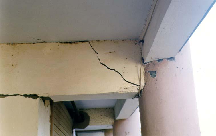
33 Shear Failure


34 Short Column Failure This failure can be avoided by providing special confining reinforcement over entire column length
35 8. P- effects may be more important than you think. The P- effects become increasingly significant with larger lateral displacements and larger axial column forces. Strong column - weak beam design strategy commonly deals with the moment capacity of columns in the undeformed state. In a substantially deformed state, the moment capacity of columns may be sufficiently reduced to counteract the strong column - weak beam behaviour envisioned by the design. Cases of plastic hinge formations during a push-over analysis in columns "designed" to be stronger than the beams are not rare.
36 9. Do not confuse the Push-over with the real earthquake loading. The push-over load is monotonically increased The earthquake generated forces continually change in amplitude and direction during the duration of earthquake ground motion. Push-over loads and structural response are in phase Earthquake excitations and building response are not necessarily in phase. This is particularly true for near-fault ground motions which tend to concentrate the damage on the lower floors, an effect which is difficult to model by the push-over loads.
37 9. Do not confuse the Push-over with the real earthquake loading Vb/W IDARC SAP 0.16g 0.25g 0.3g 0.35g /H
38 10. Three-dimensional buildings may require more than a planar push. For building with strong asymmetry in plan, or with numerous non-orthogonal elements, a planar (two dimensional) push-over analysis may not suffice. For such cases a 3D model of the building must be constructed and subjected to push-over analysis. Three dimensional buildings may be pushed in the principal directions independently, or pushed simultaneously in orthogonal directions.
39 Analysis Procedure SAP2000 NL
40 Pushover Analysis Procedure Create 3D Model Assign end offsets Gravity Pushover (Force controlled) DL+0.25LL Lateral Pushover (Displacement controlled) Define Load case (Lateral Load at centre of mass) Define Hinge properties Run Static analysis Assign Hinge properties Beams Default M3 Columns Default PMM Run static pushover analysis Define Static Pushover Cases Establish Performance point
41 Material Properties Concrete Properties Cube compressive strength, f ck Modulus of Elasticity of concrete ( E = 5000 f ) c ck Reinforcing Steel Properties Yield strength of steel Modulus of Elasticity of steel E Modulus of Elasticity of steel E s
42 Modification Factors Factors to estimate the expected strength 1.5 times the Concrete compressive strength (f( ck ) Steel yield stress (f( y ) (Factor of 1.25 used for capacity estimation considering strain hardening of steel) Knowledge Factors, m k No Description of available information m k 1 Original construction documents, including material testing report 2 Documentation as in (1) but no material testing undertaken Documentation as in (2) and minor deteriorations of original condition 4 Incomplete but usable original construction documents Documentation as in (4) and limited inspection and material test results with large variation. 6 Little knowledge about the details of components


43 Material Properties Frame Elements Infill (struts)
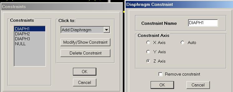
44 Modeling of Structural elements Beams and columns 3D Frame elements Slab Flat slabs Diaphragm action (ignore the out of plane stiffness) Plate elements Beam column joints End offsets (Rigid zone factor 1) Asymmetric Structures Centre of mass (add non structural mass to corresponding beams) Centre of stiffness Inclusion of appendages Include water tanks, cantilever slabs
45 Modeling of Structural elements Stairway slabs Equivalent frame elements Shear Walls Wide Column Elements Infill walls Equivalent strut method Foundation Isolated footings Single pile Multiple piles Plinth beams Hinged at the bottom of foundation Fixed at five times the diameter of pile Fixity of columns at top of pile cap Frame elements
46 Modeling of Beams and Columns 3D Frame Elements Cross Sectional dimensions, reinforcement details, material type Effective moment of inertia Beams Rectangular 0.5 I g T-Beam 0.7 I g L-Beam 0.6 I g Columns 0.7 I g

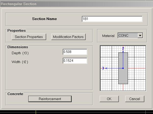

47 Modeling of Beams

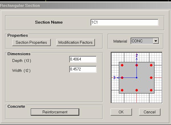
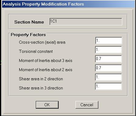
48 Modeling of Columns


49 Modeling of Beam Column Joints End offsets (Rigid zone factor 1)

50 Modeling of Slab
 Strength of infill, P b) Initial modulus of elasticity of infill, E i c) Equivalent strut width (when force in")
51 Modeling of Infill Equivalent Strut Approach Step 1. Equivalent Strut Properties Smith and Carter Model a) Strength of infill, P b) Initial modulus of elasticity of infill, E i c) Equivalent strut width (when force in the strut = R), w d) Thickness of infill, t Step 2. Stress Strain Values Stress = P/AE i,where A = wt Strain = P/A
52 Modeling of Shear Wall (Lift Core ) Type I Model - Single Lift Core Column Equivalent Wide Column Elements connected to the frame through rigid links y BEAM x MASTER NODE t Beam elements with rigid ends L
53 Modeling of Shear Wall (Lift Core ) Type II Model - Single Lift Core Column The lift core can be treated as a single column with master node defined at the centroid and the beams connected by rigid links BEAM y x CORE MASTER NODE SLAVE NODE
54 Modeling of Shear Wall (Lift Core Column Properties) For axial and torsional rigidity, the full cross-sectional sectional area should be used y BEAM x CORE MASTER NODE FOR A, J SLAVE NODE
55 Modeling of Shear Wall (Lift Core Column Properties) For shear along y axis and bending about x-axis x (ground motion along y-axis), y the walls in the direction of ground motion should be considered as two parallel elements y BEAM x CORE MASTER NODE FOR A y, I xx SLAVE NODE
56 Modeling of Shear Wall (Lift Core Column Properties) For shear along x axis and bending about y-axis y (ground motion along x-axis), x the walls in the direction of ground motion should be considered as three parallel elements y BEAM x CORE MASTER NODE FOR A x, I yy SLAVE NODE


57 Beam Hinge Properties - Flexural hinge (M 3 )

58 Hinge Properties for Beams Lateral Load 1.0 c A b a C B D E y Lateral Deformation Generalized Load Deformation Relations * ATC 40 Volume 1

59 Beam Hinge Properties - Shear hinge
60 Beam Hinge Properties - Shear hinge Shear capacity V = f A sy y sv d 0.6s Total Shear Capacity, V y = V c + V sy v = 0 Shear strength (V) V y 0.2 V y V u = 1.05V y Residual Shear Strength y m =15 y 1.5 y Shear deformation ( ) Refer Clause of IS13920

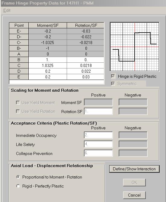
61 Column Hinge Properties- Flexural hinge (PM 2 M 3 )
62 Hinge Properties for Columns * ATC 40 Volume 1 Lateral Load 1.0 c A b a C B D E y Lateral Deformation

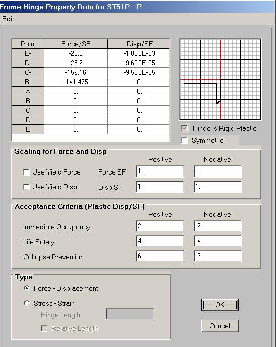
63 Column Hinge Properties- Shear hinge
64 Column Hinge Properties- Shear hinge Shear capacity τ c = where 0.8 f ( 1+ 5β 1) ck 6 β fckbd β = A 3Pu δ = A f V c g ck = δτ bd V = f A c sy y sv st d 0.6s Total Shear Capacity, V y = V c + V sy v Note: For moderate and high ductility of the column section δ = 3 P u A f g c k is taken in calculation (ATC 40) 0.5
65 Column Hinge Properties- Shear hinge Yield deformation ( y ) is to be calculated using the following formula. y = Yield shear strength Shear stiffness = R GA l eff = G R l 0.75 A g Where G = Shear modulus of the reinforced concrete section A g = Gross area of the section l = Length of member
66 Column Hinge Properties- Shear hinge The ultimate shear strength (V u ) is taken as 5% more than yield shear strength (V y ) and residual shear strength is taken as 20% of the yield shear strength for modelling of the shear hinges as shown in Figure. Shear strength (V) V y V u = 1.05V y 0.2 V y y m=15 y 1.5 Shear deformation ( ) y Residual Shear Strength Similarly maximum shear deformation is taken as 15 times the yield deformation. The values were taken as per SAP 2000 manual recommendations.
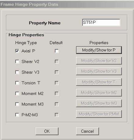
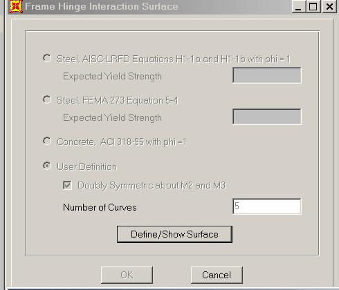
67 Infill Properties - Axial hinge (P)

68 Static Pushover Case Data (Gravity Pushover Force Controlled)
69 Lateral Load Pattern Determination of the Load pattern: (IS 1893 (part 1) : 2002 ) Fundamental natural period T a = d h Q3 Design Base Shear V B = A h W Q2 Design Lateral Force Q 2 Wihi i = VB 2 Wjhj Q1

70 Static Pushover Case Data (Lateral pushover Displacement controlled)
71 Seismic Evaluation of a Typical RC Building
72 Building Data Building frame system RC OMRF Usage Residential Built in 1999 Zone V Number of stories Footing Symmetry Material used Plan dimensions G+4 Multiple Piles About Y-axis M15 & Fe m X 13.95m Building height 15.7m Soil Type (assumed) Type-II (Medium)
73 Plan- Beam Locations n Storey number Beams (only in 1 to 4 floor)
74 Plan - Column and Equivalent Strut Locations Infill wall Location Storey number n
75 Comments Visual inspection did not reveal concrete deterioration. Knowledge factor was not applied. Architectural drawings were not available. Location of infill walls w was postulated. Geotechnical data was not available. Rebar detailing was not complete in the available structural drawings. Building considered to be noncompliant with IS 13920: 1993 (R = 3). Fixity considered at pile cap. Soil-structure interaction neglected. Elevator walls not considered as lateral load resisting elements.
76 Plan Frames along X-directionX
77 Plan Frames along Y-directionY
78 Elevation along line A-AA
79 Typical Beam Section (Ground Floor)
80 Typical Column Sections (Ground Floor) Tie spacing 100 mm c/c near beam-to-column joints
81 Detailed Structural Analysis Gravity Load Analysis Lateral Load Analysis Linear static analysis (Equivalent Static Method, IS 1893 (Part 1): 2002) Response Spectrum Method (IS 1893 (Part 1): 2002) Non-linear Static Analysis (Pushover Analysis, ATC 40)
82 Structural Parameters Floor Seismic Weight (kn) Lumped Mass (Ton) Center of Mass (m) X- direction Y- direction Center of rigidity (m) X- direction Y- direction Static Eccentricity, e si ( m) X- direction Y- direction Design Eccentricity, e di (m) X- direction Y- direction e = 1.5e b di si i e = e 0.05b di si i
83 Location of Centre of Mass
84 Calculation of Base Shear IS 1893(Part 1):2002 Base shear, V B = A h W A h ZI S 2R g a = A h = 0.15 W = Total seismic weight of the building Z = 0.36 (for Zone V) I = 1 (for normal building) R = 3 (for OMRF) S a /g = 2.5 corresponding to both the time period in with-infill case. V B = kn = 3039 kn
85 Comparison of Base Shear Analysis methods Without infill stiffness With infill stiffness V x (kn) V y (kn) V x (kn) V y (kn) Equivalent Static Method EQX EQY Response Spectrum Analysis EQ
86 Comparison of Fundamental Periods Empirical Formulae Computational Model With infill stiffness Without infill stiffness With infill stiffness Without infill stiffness Time Period (s) T ax = 0.28 T ay = S a /g
87 First five modes and their participation Without infill With infill Mode T (s) Mass Participation (%) T (s) Mass Participation (%) U X U y U X U y

 Second 76s (U")
88 Mode Shapes First Mode T=0.83s (U X =92.91%) Second Mode T=0.76s (U Y =90.51%)
 (U X =0.")
 Fourth Mode T=0.")
89 Mode Shapes Third Mode T=0.39s (RZ) (U X =0.11% U Y =0.52%) Fourth Mode T=0.25s (U X =5.39% U Y =0.04%)

90 Mode Shapes Fifth Mode T=0.24s (U X =0.03% U Y =7.07%)
 M2 (knm) M3 (knm) P (kn) M2 (knm) M3 (knm) DCR P (kn) M2 (knm) M3 (knm) DCR Mux1 PuR θ MuR,x load contour A Muy1 MuR,y Y 0 Muy = Pu ey 1C1 2871 236 207 1744 323 311 2.")
91 Demand and Capacity for Columns - Moment (Equivalent static method) Section Absolute Capacities Absolute Demand (Without Infill stiffness) Absolute Demand (With Infill stiffness) x z y Pu X Y θ ey ex X Puz Pu P (kn) M2 (knm) M3 (knm) P (kn) M2 (knm) M3 (knm) DCR P (kn) M2 (knm) M3 (knm) DCR Mux1 PuR θ MuR,x load contour A Muy1 MuR,y Y 0 Muy = Pu ey 1C Mux = Pu ex M = M + M 2 2 ur ux uy 1C C C C C
92 Demand and Capacity for Columns Shear (Equivalent Static Method) Sections Absolute Capacities V u (kn) Absolute Demand (With infill stiffness) V d (kn) DCR Absolute Demand (Without infill stiffness) V d (kn) DCR 1C C C C C C V u is higher of the shear from analysis and the shear corresponding to the flexural capacity M u (V u = M u / L s )
93 Maximum displacement response in X-direction (Equivalent Static Method) Storey Level 3 2 Storey Level Displacement (mm) Displacement (mm) With Infill Without Infill
94 Inter-storey Drift in X-direction X Equivalent Static Method Storey level (m) Storey level (m) Inter-storey drift ( X 10-2 %) Inter-storey drift ( X 10-2 %) With infill Without infill
95 Performance Objective 1. Design Basis Earthquake + Life Safety (2% total drift) 2. Maximum Considered Earthquake + Collapse Prevention (4% total drift)
96 Distribution of Lateral Force at each Storey Level for Lateral Pushover Q 5 = Q 4 = Q 3 = Q 2 = Q 1 =
97 Moment Rotation Curve for a Typical Element Hinge Property Moment/SF C B IO LS CP D E A Rotation/SF B Yield state IO Immediate Occupancy LS Life Safety CP Collapse Prevention C Ultimate state
98 Demand Spectrum Seismic Coefficient, C A Soil Zone II Zone III Zone IV Zone V (0.10) (0.16) (0.24) (0.36) Type I Type II Type III Seismic Coefficient, C V Type I Type II Type III
99 Base Shear Vs. Roof Displacement Push X V B µ = 2.41 /h = 0.49% Base Shear (kn) µ = 1.46 /h = 0.34% Roof Displacement (m) Without infill stiffness With infill stiffness
100 Base Shear Vs. Roof Displacement Push Y V B 3000 Base Shear (kn) Roof Displacement (m) Without infill stiffness With infill stiffness
101 Capacity and Demand Spectra (With infill stiffness) Spectral Accelaration Coefficient (Sa/g) Spectral Accelaration Coefficient (Sa/g) Spectral Displacement (m) Spectral Displacement (m) Lateral Push along X Lateral Push along Y
102 Capacity and Demand Spectra (Without infill stiffness) Spectral Accelaration Coefficient (Sa/g) Spectral Accelaration Coefficient (Sa/g) Spectral Displacement (m) Spectral Displacement (m) Lateral Push along X Lateral Push along Y
103 Retrofitting Scheme 1. Continuing infill walls only at a few locations. 2. Strengthening of the ground floor columns. Ground Floor Plan
104 Capacity Curve Push X C D A B /h=0.48% /h=0.75% Base Shear (kn) /h=0.28% V B /h = 1 % Roof Displacement (m)

105 State of the Hinge at A and B in Lateral load A, /h=0.28% B, /h=0.48%

106 State of the Hinge at C and D in Lateral load C, /h=0.75% D, /h=1%
107 Performance Point ( Demand spectrum- Z ) Spectral Accelaration Coefficient (Sa/g) % 15% 17.3% Demand Spectrum Capacity Spectrum Effective Period Performance Point Spectral Displacement (m) T eff = 1.224s β eff = 24.9% V = 7682 kn D = m = 0.93% of H S a = 0.29 m/s 2 S d = 0.11 m/s
108 Storey Displacements A B C D 12 H(m) Displacement (m)
109 IDI 5 4 A B C D 3 H(m) IDI
110 What if Performance Point Does Not Exist? F E ADD STRENGTH OR STIFFNESS OR BOTH V/W (Acceleration) F I Inelastic demand spectrum capacity spectrum 5% damped elastic spectrum Roof-top Displacement
111 What if Performance Point Does Not Exist? F E ENHANCE SYSTEM DUCTILITY V/W (Acceleration) F I Inelastic demand spectrum capacity spectrum 5% damped elastic spectrum Roof-top Displacement
112 What if Performance Point Does Not Exist? F E V/W (Acceleration) REDUCE SEISMIC DEMAND BY: ADDING DAMPING OR ISOLATION F I New demand spectrum 5% damped elastic spectrum Roof-top Displacement
Nonlinear static analysis PUSHOVER
 Nonlinear static analysis PUSHOVER Adrian DOGARIU European Erasmus Mundus Master Course Sustainable Constructions under Natural Hazards and Catastrophic Events 520121-1-2011-1-CZ-ERA MUNDUS-EMMC Structural
1. Background. 2. Objectives of Project. Page 1 of 29
 1. Background In close collaboration with local partners, Earthquake Damage Analysis Center (EDAC) of Bauhaus Universität Weimar initiated a Turkish German joint research project on Seismic Risk Assessment
Comparison of Structural Models for Seismic Analysis of Multi-Storey Frame Buildings
 Comparison of Structural Models for Seismic Analysis of Multi-Storey Frame Buildings Dj. Ladjinovic, A. Raseta, A. Radujkovic & R. Folic University of Novi Sad, Faculty of Technical Sciences, Novi Sad,
Seismic performance evaluation of existing RC buildings designed as per past codes of practice
 Sādhanā Vol. 37, Part 2, April 2012, pp. 281 297. c Indian Academy of Sciences Seismic performance evaluation of existing RC buildings designed as per past codes of practice 1. Introduction K RAMA RAJU,
Seismic Performance of RC Building Using Spectrum Response and Pushover Analyses
 Seismic Performance of RC Building Using Spectrum Response and Pushover Analyses Mehani Youcef (&), Kibboua Abderrahmane, and Chikh Benazouz National Earthquake Engineering Research Center (CGS), Algiers,
COLUMN INTERACTION EFFECT ON PUSH OVER 3D ANALYSIS OF IRREGULAR STRUCTURES
 th World Conference on Earthquake Engineering Vancouver, B.C., Canada August -6, Paper No. 6 COLUMN INTERACTION EFFECT ON PUSH OVER D ANALYSIS OF IRREGULAR STRUCTURES Jaime DE-LA-COLINA, MariCarmen HERNANDEZ
INELASTIC SEISMIC DISPLACEMENT RESPONSE PREDICTION OF MDOF SYSTEMS BY EQUIVALENT LINEARIZATION
 INEASTIC SEISMIC DISPACEMENT RESPONSE PREDICTION OF MDOF SYSTEMS BY EQUIVAENT INEARIZATION M. S. Günay 1 and H. Sucuoğlu 1 Research Assistant, Dept. of Civil Engineering, Middle East Technical University,
CAPACITY SPECTRUM FOR STRUCTURES ASYMMETRIC IN PLAN
 13 th World Conference on Earthquake Engineering Vancouver, B.C., Canada August 1-6, 004 Paper No. 653 CAPACITY SPECTRUM FOR STRUCTURES ASYMMETRIC IN PLAN B. K. Raghu Prasad 1, A. Seetha Ramaiah and A.
999 TOWN & COUNTRY ROAD ORANGE, CALIFORNIA TITLE PUSHOVER ANALYSIS EXAMPLE BY R. MATTHEWS DATE 5/21/01
 DESCRIPTION Nonlinear static (pushover) analysis will be performed on a railroad bridge bent using several methods to determine its ultimate lateral deflection capability. 1. SAP2000 Nonlinear with axial-moment
Sabah Shawkat Cabinet of Structural Engineering Walls carrying vertical loads should be designed as columns. Basically walls are designed in
 Sabah Shawkat Cabinet of Structural Engineering 17 3.6 Shear walls Walls carrying vertical loads should be designed as columns. Basically walls are designed in the same manner as columns, but there are
Seismic Assessment of a RC Building according to FEMA 356 and Eurocode 8
 1 Seismic Assessment of a RC Building according to FEMA 356 and Eurocode 8 Ioannis P. GIANNOPOULOS 1 Key words: Pushover analysis, FEMA 356, Eurocode 8, seismic assessment, plastic rotation, limit states
Soil-Structure Interaction in Nonlinear Pushover Analysis of Frame RC Structures: Nonhomogeneous Soil Condition
 ABSTRACT: Soil-Structure Interaction in Nonlinear Pushover Analysis of Frame RC Structures: Nonhomogeneous Soil Condition G. Dok ve O. Kırtel Res. Assist., Department of Civil Engineering, Sakarya University,
DETERMINATION OF PERFORMANCE POINT IN CAPACITY SPECTRUM METHOD
 ISSN (Online) : 2319-8753 ISSN (Print) : 2347-6710 International Journal of Innovative Research in Science, Engineering and Technology An ISO 3297: 2007 Certified Organization, Volume 2, Special Issue
ENERGY DIAGRAM w/ HYSTERETIC
 ENERGY DIAGRAM ENERGY DIAGRAM w/ HYSTERETIC IMPLIED NONLINEAR BEHAVIOR STEEL STRESS STRAIN RELATIONSHIPS INELASTIC WORK DONE HYSTERETIC BEHAVIOR MOMENT ROTATION RELATIONSHIP IDEALIZED MOMENT ROTATION DUCTILITY
CAPACITY DESIGN FOR TALL BUILDINGS WITH MIXED SYSTEM
 13 th World Conference on Earthquake Engineering Vancouver, B.C., Canada August 1-6, 24 Paper No. 2367 CAPACITY DESIGN FOR TALL BUILDINGS WITH MIXED SYSTEM M.UMA MAHESHWARI 1 and A.R.SANTHAKUMAR 2 SUMMARY
A Modified Response Spectrum Analysis Procedure (MRSA) to Determine the Nonlinear Seismic Demands of Tall Buildings
 to Determine the Nonlinear Seismic Demands of Tall Buildings") Fawad A. Najam Pennung Warnitchai Asian Institute of Technology (AIT), Thailand Email: fawad.ahmed.najam@ait.ac.th A Modified Response Spectrum Analysis Procedure (MRSA) to Determine the Nonlinear Seismic
Fawad A. Najam Pennung Warnitchai Asian Institute of Technology (AIT), Thailand Email: fawad.ahmed.najam@ait.ac.th A Modified Response Spectrum Analysis Procedure (MRSA) to Determine the Nonlinear Seismic
Chapter 6 Seismic Design of Bridges. Kazuhiko Kawashima Tokyo Institute of Technology
 Chapter 6 Seismic Design of Bridges Kazuhiko Kawashima okyo Institute of echnology Seismic Design Loading environment (dead, live, wind, earthquake etc) Performance criteria for gravity (deflection, stresses)
Design of Earthquake-Resistant Structures
 NATIONAL TECHNICAL UNIVERSITY OF ATHENS LABORATORY OF EARTHQUAKE ENGINEERING Design of Earthquake-Resistant Structures Basic principles Ioannis N. Psycharis Basic considerations Design earthquake: small
A. Belejo, R. Bento & C. Bhatt Instituto Superior Técnico, Lisbon, Portugal 1.INTRODUCTION
 Comparison of different computer programs to predict the seismic performance of SPEAR the SPEAR building building by means of by means of Pushover Analysis A. Belejo, R. Bento & C. Bhatt Instituto Superior
SEISMIC RESPONSE EVALUATION OF AN RC BEARING WALL BY DISPLACEMENT-BASED APPROACH
 3 th World Conference on Earthquake Engineering Vancouver, B.C., Canada August -, 4 Paper No. 49 SEISMIC RESPONSE EVALUATION OF AN RC BEARING WALL BY DISPLACEMENT-BASED APPROACH Chang-Hun HYUN, Sanghyun
Vertical acceleration and torsional effects on the dynamic stability and design of C-bent columns
 Vertical acceleration and torsional effects on the dynamic stability and design of C-bent columns A. Chen, J.O.C. Lo, C-L. Lee, G.A. MacRae & T.Z. Yeow Department of Civil Engineering, University of Canterbury,
PEER/SSC Tall Building Design. Case study #2
 PEER/SSC Tall Building Design Case study #2 Typical Plan View at Ground Floor and Below Typical Plan View at 2 nd Floor and Above Code Design Code Design Shear Wall properties Shear wall thickness and
Finite Element Modelling with Plastic Hinges
 01/02/2016 Marco Donà Finite Element Modelling with Plastic Hinges 1 Plastic hinge approach A plastic hinge represents a concentrated post-yield behaviour in one or more degrees of freedom. Hinges only
Lecture-08 Gravity Load Analysis of RC Structures
 Lecture-08 Gravity Load Analysis of RC Structures By: Prof Dr. Qaisar Ali Civil Engineering Department UET Peshawar www.drqaisarali.com 1 Contents Analysis Approaches Point of Inflection Method Equivalent
ROSESCHOOL ANALYSIS OF CODE PROCEDURES FOR SEISMIC ASSESSMENT OF EXISTING BUILDINGS: ITALIAN SEISMIC CODE, EC8, ATC-40, FEMA356, FEMA440
 EUROPEAN SCHOOL FOR ADVANCED STUDIES IN REDUCTION OF SEISMIC RISK ROSESCHOOL ANALYSIS OF CODE PROCEDURES FOR SEISMIC ASSESSMENT OF EXISTING BUILDINGS: ITALIAN SEISMIC CODE, EC8, ATC-40, FEMA356, FEMA440
CHAPTER 5. T a = 0.03 (180) 0.75 = 1.47 sec 5.12 Steel moment frame. h n = = 260 ft. T a = (260) 0.80 = 2.39 sec. Question No.
 0.75 = 1.47 sec 5.12 Steel moment frame. h n = = 260 ft. T a = (260) 0.80 = 2.39 sec. Question No.") CHAPTER 5 Question Brief Explanation No. 5.1 From Fig. IBC 1613.5(3) and (4) enlarged region 1 (ASCE 7 Fig. -3 and -4) S S = 1.5g, and S 1 = 0.6g. The g term is already factored in the equations, thus
CHAPTER 5 Question Brief Explanation No. 5.1 From Fig. IBC 1613.5(3) and (4) enlarged region 1 (ASCE 7 Fig. -3 and -4) S S = 1.5g, and S 1 = 0.6g. The g term is already factored in the equations, thus
EUROCODE EN SEISMIC DESIGN OF BRIDGES
 Brussels, 18-20 February 2008 Dissemination of information workshop 1 EUROCODE EN1998-2 SEISMIC DESIGN OF BRIDGES Basil Kolias Basic Requirements Brussels, 18-20 February 2008 Dissemination of information
Pushover Seismic Analysis of Bridge Structures
 Pushover Seismic Analysis of Bridge Structures Bernardo Frère Departamento de Engenharia Civil, Arquitectura e Georrecursos, Instituto Superior Técnico, Technical University of Lisbon, Portugal October
9.5 Compression Members
 9.5 Compression Members This section covers the following topics. Introduction Analysis Development of Interaction Diagram Effect of Prestressing Force 9.5.1 Introduction Prestressing is meaningful when
Civil Engineering Design (1) Design of Reinforced Concrete Columns 2006/7
 Design of Reinforced Concrete Columns 2006/7") Civil Engineering Design (1) Design of Reinforced Concrete Columns 2006/7 Dr. Colin Caprani, Chartered Engineer 1 Contents 1. Introduction... 3 1.1 Background... 3 1.2 Failure Modes... 5 1.3 Design Aspects...
Civil Engineering Design (1) Design of Reinforced Concrete Columns 2006/7 Dr. Colin Caprani, Chartered Engineer 1 Contents 1. Introduction... 3 1.1 Background... 3 1.2 Failure Modes... 5 1.3 Design Aspects...
Earthquake Loads According to IBC IBC Safety Concept
 Earthquake Loads According to IBC 2003 The process of determining earthquake loads according to IBC 2003 Spectral Design Method can be broken down into the following basic steps: Determination of the maimum
Codal Provisions IS 1893 (Part 1) 2002
 2002") Abstract Codal Provisions IS 1893 (Part 1) 00 Paresh V. Patel Assistant Professor, Civil Engineering Department, Nirma Institute of Technology, Ahmedabad 38481 In this article codal provisions of IS 1893
Abstract Codal Provisions IS 1893 (Part 1) 00 Paresh V. Patel Assistant Professor, Civil Engineering Department, Nirma Institute of Technology, Ahmedabad 38481 In this article codal provisions of IS 1893
Design of a Multi-Storied RC Building
 Design of a Multi-Storied RC Building 16 14 14 3 C 1 B 1 C 2 B 2 C 3 B 3 C 4 13 B 15 (S 1 ) B 16 (S 2 ) B 17 (S 3 ) B 18 7 B 4 B 5 B 6 B 7 C 5 C 6 C 7 C 8 C 9 7 B 20 B 22 14 B 19 (S 4 ) C 10 C 11 B 23
OS MODELER - EXAMPLES OF APPLICATION Version 1.0. (Draft)
") OS MODELER - EXAMPLES OF APPLICATION Version 1.0 (Draft) Matjaž Dolšek February 2008 Content 1. Introduction... 1 2. Four-storey reinforced concrete frame designed according to EC8... 2 2.1. Description
OS MODELER - EXAMPLES OF APPLICATION Version 1.0 (Draft) Matjaž Dolšek February 2008 Content 1. Introduction... 1 2. Four-storey reinforced concrete frame designed according to EC8... 2 2.1. Description
Harmonized European standards for construction in Egypt
 Harmonized European standards for construction in Egypt EN 1998 - Design of structures for earthquake resistance Jean-Armand Calgaro Chairman of CEN/TC250 Organised with the support of the Egyptian Organization
Seismic performance of buildings resting on sloping ground A review
 IOSR Journal of Mechanical and Civil Engineering (IOSR-JMCE) e-issn: 2278-1684,p-ISSN: 2320-334X, Volume 11, Issue 3 Ver. III (May- Jun. 2014), PP 12-19 Seismic performance of buildings resting on sloping
MODULE C: COMPRESSION MEMBERS
 MODULE C: COMPRESSION MEMBERS This module of CIE 428 covers the following subjects Column theory Column design per AISC Effective length Torsional and flexural-torsional buckling Built-up members READING:
Seismic Pushover Analysis Using AASHTO Guide Specifications for LRFD Seismic Bridge Design
 Seismic Pushover Analysis Using AASHTO Guide Specifications for LRFD Seismic Bridge Design Elmer E. Marx, Alaska Department of Transportation and Public Facilities Michael Keever, California Department
Earthquake Simulation Tests on a 1:5 Scale 10 - Story RC Residential Building Model
 Earthquake Simulation Tests on a 1:5 Scale 1 - Story RC Residential Building Model H. S. Lee, S. J. Hwang, K. B. Lee, & C. B. Kang Korea University, Seoul, Republic of Korea S. H. Lee & S. H. Oh Pusan
A METHOD OF LOAD INCREMENTS FOR THE DETERMINATION OF SECOND-ORDER LIMIT LOAD AND COLLAPSE SAFETY OF REINFORCED CONCRETE FRAMED STRUCTURES
 A METHOD OF LOAD INCREMENTS FOR THE DETERMINATION OF SECOND-ORDER LIMIT LOAD AND COLLAPSE SAFETY OF REINFORCED CONCRETE FRAMED STRUCTURES Konuralp Girgin (Ph.D. Thesis, Institute of Science and Technology,
Effect of eccentric moments on seismic ratcheting of single-degree-of-freedom structures
 Effect of eccentric moments on seismic ratcheting of single-degree-of-freedom structures K.Z. Saif, C.-L. Lee, G.A. MacRae & T.Z. Yeow Department of Civil Engineering, University of Canterbury, Christchurch.
STATIC NONLINEAR ANALYSIS. Advanced Earthquake Engineering CIVIL-706. Instructor: Lorenzo DIANA, PhD
 STATIC NONLINEAR ANALYSIS Advanced Earthquake Engineering CIVIL-706 Instructor: Lorenzo DIANA, PhD 1 By the end of today s course You will be able to answer: What are NSA advantages over other structural
Eurocode 8 Part 3: Assessment and retrofitting of buildings
 in the Euro-Mediterranean Area Eurocode 8 Part 3: Assessment and retrofitting of buildings Paolo Emilio Pinto Università di Roma La Sapienza Urgency of guidance documents for assessment and retrofit in
A Nonlinear Static (Pushover) Procedure Consistent with New Zealand Standards
 Procedure Consistent with New Zealand Standards") A Nonlinear Static (Pushover) Procedure Consistent with New Zealand Standards B. J. Davidson Compusoft Engineering Ltd, Auckland, New Zealand. 010 NZSEE Conference ABSTRACT: The Nonlinear Static Procedure,
A Nonlinear Static (Pushover) Procedure Consistent with New Zealand Standards B. J. Davidson Compusoft Engineering Ltd, Auckland, New Zealand. 010 NZSEE Conference ABSTRACT: The Nonlinear Static Procedure,
[Hussain, 4(9): September 2017] ISSN DOI /zenodo Impact Factor
![[Hussain, 4(9): September 2017] ISSN DOI /zenodo Impact Factor](/thumbs/89/98828424.jpg "[Hussain, 4(9): September 2017] ISSN DOI /zenodo Impact Factor") GLOBAL JOURNAL OF ENGINEERING SCIENCE AND RESEARCHES SEISMIC ANALYSIS OF MULTI STOREYED BUILDING WITH SOFT STOREY Mohammed Irfan Hussain* *Asst. Professor, Department of Civil Engineering, Chaitanya Institute
GLOBAL JOURNAL OF ENGINEERING SCIENCE AND RESEARCHES SEISMIC ANALYSIS OF MULTI STOREYED BUILDING WITH SOFT STOREY Mohammed Irfan Hussain* *Asst. Professor, Department of Civil Engineering, Chaitanya Institute
Force Based Design Fundamentals. Ian Buckle Director Center for Civil Engineering Earthquake Research University of Nevada, Reno
 Force Based Design Fundamentals Ian Buckle Director Center for Civil Engineering Earthquake Research University of Nevada, Reno Learning Outcomes Explain difference between elastic forces, actual forces
Engineering Science OUTCOME 1 - TUTORIAL 4 COLUMNS
 Unit 2: Unit code: QCF Level: Credit value: 15 Engineering Science L/601/10 OUTCOME 1 - TUTORIAL COLUMNS 1. Be able to determine the behavioural characteristics of elements of static engineering systems
ESTIMATING PARK-ANG DAMAGE INDEX USING EQUIVALENT SYSTEMS
 ESTIMATING PARK-ANG DAMAGE INDEX USING EQUIVALENT SYSTEMS Debarati Datta 1 and Siddhartha Ghosh 2 1 Research Scholar, Department of Civil Engineering, Indian Institute of Technology Bombay, India 2 Assistant
Civil Engineering Design (1) Analysis and Design of Slabs 2006/7
 Analysis and Design of Slabs 2006/7") Civil Engineering Design (1) Analysis and Design of Slabs 006/7 Dr. Colin Caprani, Chartered Engineer 1 Contents 1. Elastic Methods... 3 1.1 Introduction... 3 1. Grillage Analysis... 4 1.3 Finite Element
Civil Engineering Design (1) Analysis and Design of Slabs 006/7 Dr. Colin Caprani, Chartered Engineer 1 Contents 1. Elastic Methods... 3 1.1 Introduction... 3 1. Grillage Analysis... 4 1.3 Finite Element
TABLE OF CONTANINET 1. Design criteria. 2. Lateral loads. 3. 3D finite element model (SAP2000, Ver.16). 4. Design of vertical elements (CSI, Ver.9).
. 4. Design of vertical elements (CSI, Ver.9).") TABLE OF CONTANINET 1. Design criteria. 2. Lateral loads. 2-1. Wind loads calculation 2-2. Seismic loads 3. 3D finite element model (SAP2000, Ver.16). 4. Design of vertical elements (CSI, Ver.9). 4-1.
TABLE OF CONTANINET 1. Design criteria. 2. Lateral loads. 2-1. Wind loads calculation 2-2. Seismic loads 3. 3D finite element model (SAP2000, Ver.16). 4. Design of vertical elements (CSI, Ver.9). 4-1.
DEFORMATION CAPACITY OF OLDER RC SHEAR WALLS: EXPERIMENTAL ASSESSMENT AND COMPARISON WITH EUROCODE 8 - PART 3 PROVISIONS
 DEFORMATION CAPACITY OF OLDER RC SHEAR WALLS: EXPERIMENTAL ASSESSMENT AND COMPARISON WITH EUROCODE 8 - PART 3 PROVISIONS Konstantinos CHRISTIDIS 1, Emmanouil VOUGIOUKAS 2 and Konstantinos TREZOS 3 ABSTRACT
Seismic design of bridges
 NATIONAL TECHNICAL UNIVERSITY OF ATHENS LABORATORY FOR EARTHQUAKE ENGINEERING Seismic design of bridges Lecture 3 Ioannis N. Psycharis Capacity design Purpose To design structures of ductile behaviour
CE5510 Advanced Structural Concrete Design - Design & Detailing of Openings in RC Flexural Members-
 CE5510 Advanced Structural Concrete Design - Design & Detailing Openings in RC Flexural Members- Assoc Pr Tan Kiang Hwee Department Civil Engineering National In this lecture DEPARTMENT OF CIVIL ENGINEERING
Design of Beams (Unit - 8)
") Design of Beams (Unit - 8) Contents Introduction Beam types Lateral stability of beams Factors affecting lateral stability Behaviour of simple and built - up beams in bending (Without vertical stiffeners)
Design of Beams (Unit - 8) Contents Introduction Beam types Lateral stability of beams Factors affecting lateral stability Behaviour of simple and built - up beams in bending (Without vertical stiffeners)
Influence of cracked inertia and moment-curvature curve idealization on pushover analysis
 Influence of cracked inertia and moment-curvature curve idealization on pushover analysis Vivier Aurélie, Sekkat Dayae, Montens Serge Systra, 3 avenue du Coq, 75009 Paris SUMMARY: The pushover analysis
Combined Effect of Soil Structure Interaction and Infill Wall Stiffness on Building_- A Review
 Combined Effect of Soil Structure Interaction and Infill Wall Stiffness on Building_- A Review Prof. Wakchaure M. R a* a Dean & Asso. Professor, Dept.of Civil Engineering, Amrutvahini College of Engineering,
Dynamic Analysis Using Response Spectrum Seismic Loading
 Dynamic Analysis Using Response Spectrum Seismic Loading Paleti Teja M.Tech (Structural Engineering) Department of Civil Engineering Jogaiah Institute of Technology & Sciences College of Engineering Kalagampudi,
D : SOLID MECHANICS. Q. 1 Q. 9 carry one mark each. Q.1 Find the force (in kn) in the member BH of the truss shown.
 in the member BH of the truss shown.") D : SOLID MECHANICS Q. 1 Q. 9 carry one mark each. Q.1 Find the force (in kn) in the member BH of the truss shown. Q.2 Consider the forces of magnitude F acting on the sides of the regular hexagon having
D : SOLID MECHANICS Q. 1 Q. 9 carry one mark each. Q.1 Find the force (in kn) in the member BH of the truss shown. Q.2 Consider the forces of magnitude F acting on the sides of the regular hexagon having
Seismic Collapse Margin of Structures Using Modified Mode-based Global Damage Model
 Seismic Collapse Margin of Structures Using Modified Mode-based Global Damage Model X. Y. Ou, Z. He & J. P. Ou Dalian University of Technology, China SUMMARY: Collapse margin ratio (CMR) introduced in
Design of Reinforced Concrete Structures (II)
") Design of Reinforced Concrete Structures (II) Discussion Eng. Mohammed R. Kuheil Review The thickness of one-way ribbed slabs After finding the value of total load (Dead and live loads), the elements are
Design of Reinforced Concrete Structures (II) Discussion Eng. Mohammed R. Kuheil Review The thickness of one-way ribbed slabs After finding the value of total load (Dead and live loads), the elements are
Structural Steelwork Eurocodes Development of A Trans-national Approach
 Structural Steelwork Eurocodes Development of A Trans-national Approach Course: Eurocode Module 7 : Worked Examples Lecture 0 : Simple braced frame Contents: 1. Simple Braced Frame 1.1 Characteristic Loads
Feasibility of dynamic test methods in classification of damaged bridges
 Feasibility of dynamic test methods in classification of damaged bridges Flavio Galanti, PhD, MSc., Felieke van Duin, MSc. TNO Built Environment and Geosciences, P.O. Box 49, 26 AA, Delft, The Netherlands.
Static & Dynamic. Analysis of Structures. Edward L.Wilson. University of California, Berkeley. Fourth Edition. Professor Emeritus of Civil Engineering
 Static & Dynamic Analysis of Structures A Physical Approach With Emphasis on Earthquake Engineering Edward LWilson Professor Emeritus of Civil Engineering University of California, Berkeley Fourth Edition
Displacement-based methods EDCE: Civil and Environmental Engineering CIVIL Advanced Earthquake Engineering
 Displacement-based methods EDCE: Civil and Environmental Engineering CIVIL 706 - Advanced Earthquake Engineering EDCE-EPFL-ENAC-SGC 2016-1- Content! Link to force-based methods! Assumptions! Reinforced
midas Civil Dynamic Analysis
 Edgar De Los Santos Midas IT August 23 rd 2017 Contents: Introduction Eigen Value Analysis Response Spectrum Analysis Pushover Analysis Time History Analysis Seismic Analysis Seismic Analysis The seismic
ΙApostolos Konstantinidis Diaphragmatic behaviour. Volume B
 Volume B 3.1.4 Diaphragmatic behaviour In general, when there is eccentric loading at a floor, e.g. imposed by the horizontal seismic action, the in-plane rigidity of the slab forces all the in-plane points
SEISMIC PERFORMANCE OF CONCRETE COLUMNS WITH INADEQUATE TRANSVERSE REINFORCEMENT. Alistair Boys 1 Des K. Bull 2 Stefano Pampanin 3 ABSTRACT
 SEISMIC PERFORMANCE OF CONCRETE COLUMNS WITH INADEQUATE TRANSVERSE REINFORCEMENT. Alistair Boys 1 Des K. Bull 2 Stefano Pampanin 3 ABSTRACT Existing New Zealand building stock contains a significant number
Flexure: Behavior and Nominal Strength of Beam Sections
 4 5000 4000 (increased d ) (increased f (increased A s or f y ) c or b) Flexure: Behavior and Nominal Strength of Beam Sections Moment (kip-in.) 3000 2000 1000 0 0 (basic) (A s 0.5A s ) 0.0005 0.001 0.0015
CHAPTER 4. ANALYSIS AND DESIGN OF COLUMNS
 4.1. INTRODUCTION CHAPTER 4. ANALYSIS AND DESIGN OF COLUMNS A column is a vertical structural member transmitting axial compression loads with or without moments. The cross sectional dimensions of a column
PACIFIC EARTHQUAKE ENGINEERING RESEARCH CENTER
 PACIFIC EARTHQUAKE ENGINEERING RESEARCH CENTER PACIFIC EARTHQUAKE ENGINEERING Performance and Reliability of Exposed Column Base Plate Connections for Steel Moment-Resisting Frames Ady Aviram Bozidar Stojadinovic
Seismic Response Analysis of Structure Supported by Piles Subjected to Very Large Earthquake Based on 3D-FEM
 Seismic Response Analysis of Structure Supported by Piles Subjected to Very Large Earthquake Based on 3D-FEM *Hisatoshi Kashiwa 1) and Yuji Miyamoto 2) 1), 2) Dept. of Architectural Engineering Division
An Investigation on the Correlation of Inter-story Drift and Performance Objectives in Conventional RC Frames
 Available online at www.ijournalse.org Emerging Science Journal Vol., No. 3, June, 18 An Investigation on the Correlation of Inter-story Drift and Performance Objectives in Conventional RC Frames Saeed
twenty one concrete construction: shear & deflection ARCHITECTURAL STRUCTURES: FORM, BEHAVIOR, AND DESIGN DR. ANNE NICHOLS SUMMER 2014 lecture
 ARCHITECTURAL STRUCTURES: FORM, BEHAVIOR, AND DESIGN DR. ANNE NICHOLS SUMMER 2014 lecture twenty one concrete construction: Copyright Kirk Martini shear & deflection Concrete Shear 1 Shear in Concrete
This Technical Note describes how the program checks column capacity or designs reinforced concrete columns when the ACI code is selected.
 COMPUTERS AND STRUCTURES, INC., BERKELEY, CALIFORNIA DECEMBER 2001 CONCRETE FRAME DESIGN ACI-318-99 Technical Note This Technical Note describes how the program checks column capacity or designs reinforced
Dynamic Analysis of a Reinforced Concrete Structure Using Plasticity and Interface Damage Models
 Dynamic Analysis of a Reinforced Concrete Structure Using Plasticity and Interface Damage Models I. Rhee, K.J. Willam, B.P. Shing, University of Colorado at Boulder ABSTRACT: This paper examines the global
QUALITATIVE COMPARISON OF STATIC PUSHOVER VERSUS INCREMENTAL DYNAMIC ANALYSIS CAPACITY CURVES
 QUALITATIVE COMPARISON OF STATIC PUSHOVER VERSUS INCREMENTAL DYNAMIC ANALYSIS CAPACITY CURVES Michalis Fragiadakis Department of Civil and Environmental Engineering, University of Cyprus, Cyprus Department
EARTHQUAKE SIMULATION TESTS OF BRIDGE COLUMN MODELS DAMAGED DURING 1995 KOBE EARTHQUAKE
 EARTHQUAKE SIMULATION TESTS OF BRIDGE COLUMN MODELS DAMAGED DURING 1995 KOBE EARTHQUAKE J. Sakai 1, S. Unjoh 2 and H. Ukon 3 1 Senior Researcher, Center for Advanced Engineering Structural Assessment and
SERVICEABILITY OF BEAMS AND ONE-WAY SLABS
 CHAPTER REINFORCED CONCRETE Reinforced Concrete Design A Fundamental Approach - Fifth Edition Fifth Edition SERVICEABILITY OF BEAMS AND ONE-WAY SLABS A. J. Clark School of Engineering Department of Civil
DYNAMIC ANALYSIS OF TALL BUILDING UNDER PULSATION WIND EXCITATION
 ASIAN JOURNAL OF CIVIL ENGINEERING (BUILDING AND HOUSING) VOL. 7, NO. 1 (2006) PAGES 95-104 DYNAMIC ANALYSIS OF TALL BUILDING UNDER PULSATION WIND EXCITATION S.M. Auta and A.M. Maslennikov St. Petersburg
HIERARCHY OF DIFFICULTY CONCEPT: COMPARISON BETWEEN LINEAR AND NON LINEAR ANALYSES ACCORDING TO EC8
 HIERARCHY OF DIFFICULTY CONCEPT: COMPARISON BETWEEN LINEAR AND NON LINEAR ANALYSES ACCORDING TO EC8 Gennaro Magliulo 1, Giuseppe Maddaloni 2, Edoardo Cosenza 3 1 Assistant Professor, University of Naples
SOIL-STRUCTURE INTERACTION, WAVE PASSAGE EFFECTS AND ASSYMETRY IN NONLINEAR SOIL RESPONSE
 SOIL-STRUCTURE INTERACTION, WAVE PASSAGE EFFECTS AND ASSYMETRY IN NONLINEAR SOIL RESPONSE Mihailo D. Trifunac Civil Eng. Department University of Southern California, Los Angeles, CA E-mail: trifunac@usc.edu
Behavior and Modeling of Existing Reinforced Concrete Columns
 Behavior and Modeling of Existing Reinforced Concrete Columns Kenneth J. Elwood University of British Columbia with contributions from Jose Pincheira, Univ of Wisconsin John Wallace, UCLA Questions? What
PERIYAR CENTENARY POLYTECHNIC COLLEGE PERIYAR NAGAR - VALLAM THANJAVUR. DEPARTMENT OF MECHANICAL ENGINEERING QUESTION BANK
 PERIYAR CENTENARY POLYTECHNIC COLLEGE PERIYAR NAGAR - VALLAM - 613 403 - THANJAVUR. DEPARTMENT OF MECHANICAL ENGINEERING QUESTION BANK Sub : Strength of Materials Year / Sem: II / III Sub Code : MEB 310
Influence of First Shape Factor in Behaviour of Rubber Bearings Base Isolated Buildings.
 ISSN (Online) 2347-327 Influence of First Shape Factor in Behaviour of Rubber Bearings Base Isolated Buildings. Luan MURTAJ 1, Enkelejda MURTAJ 1 Pedagogue, Department of Structural Mechanics Faculty of
Lecture-09 Introduction to Earthquake Resistant Analysis & Design of RC Structures (Part I)
") Lecture-09 Introduction to Earthquake Resistant Analysis & Design of RC Structures (Part I) By: Prof Dr. Qaisar Ali Civil Engineering Department UET Peshawar www.drqaisarali.com 1 Topics Introduction Earthquake
Lecture-09 Introduction to Earthquake Resistant Analysis & Design of RC Structures (Part I) By: Prof Dr. Qaisar Ali Civil Engineering Department UET Peshawar www.drqaisarali.com 1 Topics Introduction Earthquake
SPREAD OF PLASTICITY ANALYSIS OF R/C BUILDINGS, SUBJECTED TO MONOTONIC SEISMIC LOADING
 13 th World Conference on Earthquake Engineering Vancouver, B.C., Canada August 1-6, 24 Paper No. 2229 SPREAD OF PLASTICITY ANALYSIS OF R/C BUILDINGS, SUBJECTED TO MONOTONIC SEISMIC LOADING Petros MARATHIAS
IMPORTANT FEATURES OF THE RESPONSE OF INELASTIC STRUCTURES TO NEAR-FIELD GROUND MOTION
 IMPORTANT FEATURES OF THE RESPONSE OF INELASTIC STRUCTURES TO NEAR-FIELD GROUND MOTION Wilfred D IWAN 1, Ching-Tung HUANG 2 And Andrew C GUYADER 3 SUMMARY Idealized structural models are employed to reveal
Comparative study between the push-over analysis and the method proposed by the RPA for the evaluation of seismic reduction coefficient
 33, Issue (27) 5-23 Journal of Advanced Research in Materials Science Journal homepage: www.akademiabaru.com/arms.html ISSN: 2289-7992 Comparative study between the push-over analysis and the method proposed
Application of Capacity Spectrum Method to timber houses considering shear deformation of horizontal frames
 Application of Capacity Spectrum Method to timber houses considering shear deformation of horizontal frames Kawai, N. 1 ABSTRACT Relating to the revision of Building Standard Law of Japan, the application
Buildings with high seismic risk. Unsafe Buildings
 Buildings with high seismic risk Unsafe Buildings AN EQUIVALENT LINEARIZATION PROCEDURE FOR DISPLACEMENT-BASED SEISMIC ASSESSMENT M. Selim GÜNAY and Haluk SUCUOĞLU Middle East Technical University Ankara,
Design of reinforced concrete sections according to EN and EN
 Design of reinforced concrete sections according to EN 1992-1-1 and EN 1992-2 Validation Examples Brno, 21.10.2010 IDEA RS s.r.o. South Moravian Innovation Centre, U Vodarny 2a, 616 00 BRNO tel.: +420-511
Where and are the factored end moments of the column and >.
 11 LIMITATION OF THE SLENDERNESS RATIO----( ) 1-Nonsway (braced) frames: The ACI Code, Section 6.2.5 recommends the following limitations between short and long columns in braced (nonsway) frames: 1. The
CHAPTER 4. Design of R C Beams
 CHAPTER 4 Design of R C Beams Learning Objectives Identify the data, formulae and procedures for design of R C beams Design simply-supported and continuous R C beams by integrating the following processes
Evaluation of the ductility demand in partial strength steel structures in seismic areas using non-linear static analysis
 Evaluation of the ductility demand in partial strength steel structures in seismic areas using non-linear static analysis Pedro Nogueiro Department of Applied Mechanics, ESTiG, Polytechnic Institute of
SERVICEABILITY LIMIT STATE DESIGN
 CHAPTER 11 SERVICEABILITY LIMIT STATE DESIGN Article 49. Cracking Limit State 49.1 General considerations In the case of verifications relating to Cracking Limit State, the effects of actions comprise
Estimation of the Residual Stiffness of Fire-Damaged Concrete Members
 Copyright 2011 Tech Science Press CMC, vol.22, no.3, pp.261-273, 2011 Estimation of the Residual Stiffness of Fire-Damaged Concrete Members J.M. Zhu 1, X.C. Wang 1, D. Wei 2, Y.H. Liu 2 and B.Y. Xu 2 Abstract:
Influence of Modelling Issues on Nonlinear Static Seismic Analysis of a Regular 3D Steel Structure. A. Belejo; R. Bento - Maio de
 ISSN: 871-7869 Influence of Modelling Issues on Nonlinear Static Seismic Analysis of a Regular 3D Steel Structure A. Belejo; R. Bento - Maio de 212 - Relatório ICIST DTC nº 13/212 LIST OF CONTENTS LIST
SEISMIC RESPONSE OF SINGLE DEGREE OF FREEDOM STRUCTURAL FUSE SYSTEMS
 3 th World Conference on Earthquake Engineering Vancouver, B.C., Canada August -6, 4 Paper No. 377 SEISMIC RESPONSE OF SINGLE DEGREE OF FREEDOM STRUCTURAL FUSE SYSTEMS Ramiro VARGAS and Michel BRUNEAU
Comparison of Base Shear Force Method in the Seismic Design Codes of China, America and Europe
 Applied Mechanics and Materials Vols. 66-69 (202) pp 2345-2352 Online available since 202/May/4 at www.scientific.net (202) Trans Tech Publications, Switzerland doi:0.4028/www.scientific.net/amm.66-69.2345
DYNAMIC RESPONSE OF EARTHQUAKE EXCITED INELASTIC PRIMARY- SECONDARY SYSTEMS
 DYNAMIC RESPONSE OF EARTHQUAKE EXCITED INELASTIC PRIMARY- SECONDARY SYSTEMS Christoph ADAM 1 And Peter A FOTIU 2 SUMMARY The objective of the paper is to investigate numerically the effect of ductile material