Control de robots y sistemas multi-robot basado en visión
|
|
|
- Laureen Pitts
- 5 years ago
- Views:
Transcription

1 Control de robots y sistemas multi-robot basado en visión Universidad de Zaragoza Ciclo de conferencias Master y Programa de Doctorado en Ingeniería de Sistemas y de Control UNED ES Ingeniería Informática April -014 Colaboradores: Gonzalo López Nicolás Héctor Manuel Becerra Rosario Aragüés Eduardo Montijano Miguel Aranda Universidad de Zaragoza 1


2 Motivation
3 Index Features. FM, H, (Fundamental Matriz, Homography and rifocal ensor) Visual mobile robot control FM based H based based Long term navigation Control of Multi-robot systems Data association Coordinated motion with epipoles Central decision with flying camera on scene - Homography 3


4 Features Harris corner extractor Puntos extraidos de la primera imagen Lines SIF SURF 4
5 FM: Fundamental Matriz p X Image 1 Image C x Fx x l l e e Base Line C 5
6 Fundamental Matrix FM: Matriz Fundamental Matrix 3x3 satisfying: x Fx=0 Independent of scene structure As a dot product: (x x, x y, x, y x, y y, y, x, y, 1) f = 0 With 8 points we have: A f=0 8 points=> Solution to scale factor SVD(A) => Singular vector of smallest singular value 6


7 H: Homography Projective trasformation between two planes X π X? x x H π l C e e C 7


8 H: Homography 8 x = Hx = ' x x x h h h h h h h h h x x x H
9 : rifocal tensor (1D) 9
10 : rifocal tensor he tensor 1D has xx elements, wl < 3w 3+l 1, 5 features needed he D tensor has 3x3x3 elements 10


11 Nonholonomic Epipolar Visual Servoing FM based arget image Desired epipole trajectories Features extraction Robot Matching Epipolar geometry Control law Features extraction Current image 11


12 Nonholonomic Epipolar Visual Servoing FM based arget image arget Current image C t Planar motion C t Current C c C c with 1
13 Nonholonomic Epipolar Visual Servoing FM based Desired epipole trajectories Epipoles evolution Invertible if det#0 det( L) Singularidad ecx = 0 ( θ + ψ )/ d sin ( ψ ) sin ( θ ψ ) = α x cos + ( θ +ψ ) = 90º 13


14 Nonholonomic Epipolar Visual Servoing FM based Matches Epipoles and epipolar lines 14


15 Nonholonomic Epipolar Visual Servoing FM based arget position arget image Current image 15


16 Nonholonomic Epipolar Visual Servoing FM based 16
17 e 13 = e 3 e, e 1 1 Nonholonomic Epipolar Visual Servoing FM based Sliding mode control to avoid singularity he control task is carried out in two steps: y e = 31 e 3 C 3 x First step Alignment with the target e 13 e 1 = y 0 e 3 e 31 e 3 = 0 e 1 C C = C 1 C 1 C 1 Initial configuration Intermediate configuration Final configuration C 3 e 1 x ( e3 = 0) &( e3 = 0) ( x = 0,φ = 0) Second step Depth correction e 1 = e 13 ξ e, e 3 3 y e = 1 e 31 x C = C 3 1 = e1 e13 ξ1 = 0 y = 0 17
18 Nonholonomic Epipolar Visual Servoing FM based Control goal of the step Solve the stabilization problem in the following error d d system, where ξ 3 = e3 e3(t), ξ3 = e3 e3(t). Desired trajectories α x sin( φ ψ ) α x d 3 d cos ( ) cos ( ) e 3 υ e φ ψ φ ψ 3 d e = ( ) L(, ) u e x sin = d α φ ψ 0 φ ψ d 3( 0) π ( t) = σ 1+ cos t 3 τ 3 d ( ) e cos ω 3 3 ψ e e d 3( 0) π ( t) = 1+ cos t 3 τ where L( φ, ψ ) is the so-called decoupling matrix. ξ ξ Sliding mode control with sliding surfaces d sc ξ 3 e 3 e3 s = = = = 0. d st ξ 3 e3 e3 Decoupling-based controller. u υ ω cos cos ( ψ ) ( φ ψ ) d3e db 1 0 sin db = = db α xe ( φ ψ ) cos ( ψ ) u u c t Singularity if φ ψ = nπ where u c u t = e = e d 3 λcsc κc d 3 λtst κt sign( s ), sign c ( s ) t 18
19 Nonholonomic Epipolar Visual Servoing FM based A singular pose is shown in the figure φ ψ = arctan( e3 / α x ) = 0 e 3 C 3 e 3 = 0 Bounded controller. hese inputs don t use the decoupling matrix ( ). υb kυ sign st sin( φ ψ ) ub = = ( ) ωb kω sign sc his is a local control law for the error system. By switching between controllers accordingly, robust global stabilization of the error system is achieved. d d Robust Control Law e Epipolar Geometry e, e 3 3 ψ φ ψ e3, 3 Decoupling Based control Bounded control u db u b C e 3 If < h, hen u b Else u db u 19
.")
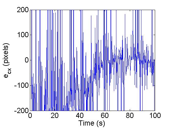
20 Nonholonomic Epipolar Visual Servoing FM based he epipoles are computed from synthetic images of size 640x480 pixels. arget location is (0,0,0º). Virtual scene: 0
 e 3 (pixels) 00 0-00 Desired trajectory Real evolution e 3 (pixels) 0 5 10 15 0 5 30 300 00 100 0-100 0 5 10 15 0 5 30 70 e 1")
21 Nonholonomic Epipolar Visual Servoing FM based 0. υ (m/s) ω (rad/s) ime (s) e 3 (pixels) Desired trajectory Real evolution e 3 (pixels) e 1 (pixels) ime (s) 1
22 Nonholonomic Homography based H based wo images can be geometrically linked by a homography he homography is generated by a plane of the scene he homography can be computed from point matches Goal: H = I p p p 1 C C 1 H p = H p 1 π
23 Nonholonomic Homography based H based he homography is related to camera motion: Planar motion: with: Non-linear relation of H with state system: 3


24 Nonholonomic Homography based VS dof system wo elements of the homography are enough to define the control Derivatives of the output functions: State space form with: State vector: Input vector: Output vector: Linear relation between the input and output with: 4


25 Nonholonomic Homography based H based racking of the desired trajectories of the homography elements Input of the control: Exponentially stable error dynamics Desired trajectories: 5

26 Nonholonomic Homography based H based 6

27 7


28 Combination of Epipoles/Homographies for VS Path Epipoles Homography Epipolar-based control: 8


29 Combination of Epipoles/Homographies for VS Epipoles Homography Path Homography-based control: 9


30 Combination of Epipoles/Homographies for VS arget image Extraction of features Matching δ 1-δ 1-δ Robot δ Extraction of features Current image 30

31 Combination of Epipoles/Homographies for VS 31

32 Visual control based he trifocal tensor is the intrinsic geometry between three views. It only depends on the camera internal parameters and relative pose. he trifocal tensor encapsulates this intrinsic geometry. Matrix notation Seven correspondences needed 3


33 Visual control based arget image Initial image Extraction of features Extraction of features Feature matching and estimation of the trifocal tensor Control law Mobile robot Extraction of features Current image 33
.")

34 Visual control based Particularly the 1D trifocal tensor allows: Exploit the bearing information. Reduce the camera calibration parameters required for control (center of projection and vertical alignment). he trifocal tensor is a more general geometric constraint than epipolar geometry. Epipolar geometry is ill-conditioned with short baseline and with planar scenes. Five corresponding points X = [ X Y Z] i= 1 j= 1 k = 1 ijk u v i j w k = 0 v = [ v 1 v ] w = [ w 1 w ] x0 x x0 θv u = [ u 1 u] θ u θ w θ 34
35 Visual control based Initial location C1 = ( x1, y1, φ1 ). arget location C = 3 ( 0, 0, 0). Current location (moving camera) = ( x, y, ). y 1 φ 1 θ i1 C 1 X x 1 y C φ θ i x θ i3 φ 1 C 1 X t y1 1 x 1 C φ t x1 φ y t y t x y 3 C 3 C y x x 3 8 elements of the tensor: m ijk = m 111 m 11 m 11 m 1 m 11 m 1 m 1 m t y sinφ t 1 y sinφ 1 t y cosφ + t 1 y cosφ 1 t + y cosφ t 1 x sinφ 1 t y sinφ t 1 x cosφ 1 = t x sinφ 1 t y cosφ 1 tx cosφ t φ 1 y sin 1 t cosφ + x1 tx cosφ 1 tx sinφ + t sinφ1 1 x where the relative locations between cameras are given as tx cosφi sinφi = x i i t y sinφi cosφi y i i for i =1,. his is an over-constrained measurement 35
36 Visual control based Values of the trifocal tensor in particular locations When C =C 1 When C =C 3 ( t x = t, ) x t 1 y = t y 1 ( t x, t 0) = 0 y = = 0, = 0, = 0, = 0, 11 1 = 0, = 0, = 0, = 0, = 0, = 0. = 0, = 0. φ 1 C 1 t y1 1 x 1 t x1 t x C 3 φ t y y y 3 C y x x 3 ime-derivatives of the elements of the tensor = sinφ = 1 m N υ + cosφ 1 m N 11 υ + ω, 1 ω, 11 1 = = cosφ 1 m N sinφ 1 m N υ + υ + 1 ω, ω, 11 1 = = ω, ω, 1 = = 11 1 ω, ω. Useful only for orientation control 36
37 Visual control based hree variables to desired values but we choose to make a Square control system. υ y ω Visual measurements Error Function y 1 By using two outputs, the tensor provides three possibilities: First part of the control Second part Correcting DOF Drawback ( φ, y) 1 Orientation and depth Lateral error (x) Non-holonomic constraint does not allow to correct the remainder lateral error. ( φ, x) Orientation and lateral error Depth ( y) Unknown final values of the tensor elements to define the control objective. ( x, y) 3 Lateral error and depth Orientation (φ) Differential-drive allows to correct the remainder orientation error. 37
38 Position correction with two selected outputs: When Zero dynamics: Control goal of the step Stabilize the following error system, where and he initial orientation introduces uncertainty in this system and a robust control law is required. 1 φ [ ] { } [ ] { }.,, R y x Z = = φ φ ξ ξ φ., = + = ξ ξ. sin cos cos sin = = y x t t φ φ φ φ ξ ξ, d e ξ = ξ d e ξ = ξ ( ). ξ u M, sin cos d d d m N m N e e = = φ ξ ξ ω υ φ φ. cos cos + + = + + = t t ini ini d ini ini d τ π ξ τ π ξ Desired trajectories 38 Visual control based
39 Visual control based Position correction: It is carried out by two controllers, because the first one has a singularity problem when the robot is reaching the target location. Sliding mode control with sliding surfaces: d s1 e1 ξ 1 ξ1 s = = = = 0. d s e ξ1 ξ Decoupling-based controller υdb 1 = = u u sinφ1 cosφ db 1 ω db det M m m N N 1 m m where det( M) = [( ) ( ) ] m sinφ cosφ1, N = 11 N d d u1 = ξ1 λ1s1 κ1sign( s1 ), u = ξ λs κ sign( s ). Bounded controller u b υb = = ωb k 1 1 ( ) u ω k υ sign( s sign ( ( s ) )) Singularity if det( M) = 0. At the final location Robust global stabilization of the error system is achieved by commuting from the decoupling controller to the bounded one if det( M) <. h 39
40 Visual control based Correction orientation: We can use any single tensor element whose dynamics depends on and its final value being zero. ω Control goal of the step Stabilization of the following dynamics ω 1 1 = 11 ω. A suitable input that yields exponentially stable is 1 ω = k ω, t >τ 11 When position correction has been reached, and consequently, 1 = t y1 cosφ if = 0 then φ = nπ 1 with n, and the orientation is corrected. Z Although only a rotation is needed, the same bounded translational velocity is used to maintain the longitudinal position under closed loop control. υ = k υ sign( s 1 ). 40


41 Visual control based he 1D- is computed from synthetic images of size 104x768 pixels. he desired pose is (0,0,0º). Virtual scene: 41
42 Visual control with FoV constraints Scene Scene φ z x arget φ z x arget Initial Inicial arget 4

43 Visual control with FoV constraints Observed target Initial positions II O II Goal I IV G V III I III 43


44 Visual control with FoV constraints he homography between two views is related to camera motion: Planar motion: With: arget: Plane of the scene Goal: H = I Subgoals: H = Observed target: π Initial H Goal 44


45 Visual control with FoV constraints Particular homographies in particular positions 45

46 Visual control with FoV constraints Switched control: hree sequential steps Step 1: Step : Step 3: 46
47 Visual control with FoV constraints Switched control: Five sequential steps Subgoals G 1 : Pure rotation until reaching the first -curve G : Follow the first -curve forward G 3 : Pure rotation until reaching the second -curve G 4 : Follow the second -curve backward G 5 : Pure rotation until reaching desired Goal 47


48 Visual control with FoV constraints Switched control: Five sequential steps Step 1: Step 4: Step : Step 5: Step 3: Subgoals: Defined in terms of homography parameters Decomposition of the homography 48

49 Visual control with FoV constraints 49


50 Visual control with FoV constraints 50


")

51 Long term navigation ask: reach a desired position associated with a target image, which belongs to a visual memory acquired in a teaching phase. A visual path of n key images is extracted from the visual memory, which must be followed autonomously in order to reach the target. arget Home n Key images Initial Issues in previous work in the literature: 1) Constrained field of view of conventional cameras. ) Change of velocities when change of image. 3) Information about velocity in the visual path. 51
52 Long term navigation ψ he omnidirectional cameras can be virtually represented as conventional cameras when working with points on the sphere. y φ e c C c x + φ d y Each one of the key images is used as target image accordingly. e t C t x arget location Current location Epipoles e e c t x = α x. y Interaction with the robot velocities: α x sin e c d cos e t C = t C c = α x sin = d cos ( 0, 0, 0) ( ) x, y,φ xcosφ + ysinφ = α x, y cosφ xsinφ ( ) α x + ( ) cos ( φ ψ ) φ ψ υ φ ψ ( φ ψ ) ( ψ ) υ = ω, 5
53 he current epipole gives information of the translation direction and it is directly related to the required robot rotation to be aligned with the target. Use of the x-coordinate of the current epipole as feedback information to control the robot heading and so, to correct the lateral deviation. Non-null translational velocity Long term navigation υ 0 k ce ce ω = tωrt + ω ce. First component of the rotational velocity i C c i e c = 0 φ i i C t x i e c i+1 0 y i i+1 C t i+1 = 0 e c x i+1 y i+1 ω f ( e c ) Second component of the rotational velocity x i 1 y i 1 i 1 C t ki e, c i 1 = 0 i C t x i y i ki i e, c 0 i+1 C t x i+1 y i+1 ω f ( e ki c ) 53
54 Long term navigation Let us define a tracking error to drive the epipole smoothly to zero for every segment between key images d ζ ce = ec ec ( t) = 0. where k c e e d c d c > 0. ( t) = ec ( 0) π 1+ cos t, 0 t τ τ ( t) = 0, t > τ ( φ ψ ) α x υ + ( φ ψ ) cos ( φ ψ ) α x sin = ω rt d cos ζ ce ω ce rt with Control goal Stabilization of the error system: ce e ( φ ψ ) cos ( φ ψ ) d υ + ( e k ζ ). sin = d α x dmin τ =. υ Considering that the translational velocity is known, the following rotational velocity, referred as reference tracking (R) control, stabilizes the error system with c d c. c ce 54
55 A varying translational velocity according to the shape of the path can be computed depending on the epipoles between key images. υ ce = υ max + υ min υ + ce ω = max k υ kmυ d min ce min e ki c ce ce ω = tωrt + tanh 1 We propose the following nominal rotational velocity, which is computed from the epipoles between key images: So that, the complete rotational velocity (R+ control) is given as: Switching and stop condition Long term navigation he switching condition to the next key image or to stop the task is given when the image error starts to increase, which is defined as follows: r 1 ε = r j=1 p j p i, j. ω. ce. e ki c / d σ min. 55


56 Long term navigation 56
57 Index Features. FM, H, (Fundamental Matriz, Homography and rifocal ensor) Visual mobile robot control FM based H based based Long term navigation Control of Multi-robot systems Data association Coordinated motion with epipoles Central decision with flying camera on scene - Homography 57
 Communication graphs Nodes: the robots Edges: link between robots that can exchange")

58 Robots communication is limited Wireless network. Range-limited. Visibility (Comm.) Communication graphs Nodes: the robots Edges: link between robots that can exchange data Multi-Robot Systems Each robot exchange data with its one-hop neighbors Robots are moving: new edges may appear / previous links disappear Communication graphs with switching topology 58


59 Distributed Data Association Limited communication: Locally associate features with neighbors Propagate local associations through the network Inconsistent global associations Distributed algorithms: propagate local associations detect inconsistencies resolve them Additionally, establish global labels for the features 59


60 Distributed Data Association Each robot in the team has a set of features. It has executed a local association method to match its features and its neighbors ones, for his information can be represented with graph, where the nodes are the features of all the robots, and there is a link between two features if they have been locally matched by. he adjacency matrix of this graph is with 60
61 Distributed Data Association Goal (robot i). Discover for each the features, all the other features which are connected to through a path. Idea. If there is a link between features and, then the features connected to and to through a path are the same. Formal. Distributed computation of the powers of the adjacency matrix, Each robot maintains the rows of the adjacency matrix power associated to its own features, and updates them using data from its neighbors For each of this features, each robot i obtains all connected to through a path, and detects the inconsistent ones. 61
62 Distributed Data Association Idea: break local associations so that there are no two features from the same robot related by a path. Note that each inconsistency is motivated by, at least, one spurious local link (false positives). All local links are equal Resol. algorithm based on rees For each conflictive feature belonging to the same robot, use it as root of its tree and incrementally add features linked to it. If a feature already belongs to a tree, or receives requests from more than a tree, it selects one of the trees and erases links to the others. Links with quality information Maximum Error Cut For each pair of inconsistent features belonging to same robot, select and erase the link with the largest error that breaks the inconsistency. 6


 Merged map after 0")
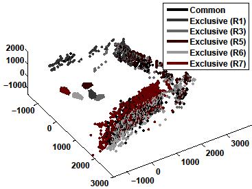
63 Distributed Data Association Compute the robot positions in a common reference frame Each robot measures the relative position of its neighbors Distributed map merging scenario Local maps aligned before merging It only needs to be computed once (a) Merged map after 5 iterations (b) Merged map after 0 iterations 63


64 Distributed Data Association 64


65 Multi robot control based on epipoles Coordinated control for attitude sincronization Modeled with an undirected graph Non holonomic motion on the plane Polar coordinates 65
66 Multi robot control based on epipoles he robots exchange the visual features Correspondences satisfy the epipolar constraint he epipoles are the null space of he attitude consensus implies the epipoles to be equal Note that the opposite is not necessarily true 66
67 Multi robot control based on epipoles Define he geodesic in the epipole domain If the calibration is known, then choosing the exact relative orientation can be computed and we have a standard consensus problem 67
68 Multi robot control based on epipoles he distributed controller used by the robots is Properties of the controller 68

69 Multi robot control based on epipoles 69
70 Multi robot control with flying camera (H) What? Visual control of mobile robots Desired configuration defined by an image ask: Navigate to the desired configuration Image of desired configuration Initial configuration Desired configuration 70


71 Multi robot control with flying camera (H) What? Visual control of mobile robots Who? Set of nonholonomic vehicles Nonholonomic kinematics Cartesian coordinates Polar coordinates 71
72 Multi robot control with flying camera (H) What? Visual control of mobile robots Who? Set of nonholonomic vehicles How? Flying camera Flying camera looking downward Camera motion unknown Intrinsic camera parameters known Homography: Only visual information 7
73 Multi robot control with flying camera (H) What? Visual control of mobile robots Who? Set of nonholonomic vehicles How? Flying camera Where? Motion occurs in a planar floor his gives additional constraints on the homography Only the set of robots may remain common in the scene Image of desired configuration: Desired configuration Actual configuration 73


74 Multi robot control with flying camera (H) he homography in our framework: Multi-robot motion in a planar floor Points = Robots => Homography Camera flies parallel to the floor C hen, the homography is constrained: p p π his homography can be computed from a minimal set of two points/robots 74
75 Multi robot control with flying camera (H) If the robots are in the desired configuration: he homography is conjugate to a planar Euclidean transformation he homography is not the identity matrix Extracting Motion parameters Which is coherent with a rigid motion. So, the robots are in the desired formation Desired configuration Desired configuration Current image Current configuration 75
76 Multi robot control with flying camera (H) If the robots are NO in the desired configuration: he homography is a similarity transformation with isotropic scaling s he H computation with the -point method Extracting Motion parameters Which is NO coherent with a rigid motion. So, the robots are not in formation Desired configuration Desired configuration Current image Current configuration 76


77 Multi robot control with flying camera (H) We have controller Robots not in formation Nonrigid homography Each pair of robots induces a different Homography, valid but not coherent We want Robots in formation Rigid homography Every pair of robots induce the same Homography We define a desired homography Like the nonrigid homography but being induced by keeping the motion constraints he task is to drive the robots to the desired homography he desired homography is not constant and depends on the robots and camera motion 77

78 Multi robot control with flying camera (H) Image of desired configuration Current image Flying camera arget homography Control law Set of robots: 78
 Image-based control law Control")


79 Multi robot control with flying camera (H) Image-based control law Control error: Current state of the robots on the image vs desired states given by the desired homography Switched control consisting of three sequential steps: Image plane 79


80 Multi robot control with flying camera (H) Steps 1- orientate and drive the robots toward their target locations. In practice, they are carried out simultaneously: Step 3 rotates the robots until they are in the required relative orientation within the formation Image of desired configuration Steps 1- Step 3 80

 op view")


81 Multi robot control with flying camera (H) op view Linear velocity: v op view Homography entries Angular velocity: ω Desired configuration: Desired configuration: 81


82 8
83 Control de robots y sistemas multi-robot basado en visión Universidad de Zaragoza Ciclo de conferencias Master y Programa de Doctorado en Ingeniería de Sistemas y de Control UNED ES Ingeniería Informática April -014 Colaboradores: Gonzalo López Nicolás Héctor Manuel Becerra Rosario Aragüés Eduardo Montijano Miguel Aranda Universidad de Zaragoza 83
Multi-Robotic Systems
 CHAPTER 9 Multi-Robotic Systems The topic of multi-robotic systems is quite popular now. It is believed that such systems can have the following benefits: Improved performance ( winning by numbers ) Distributed
Pose-Estimation-Based Visual Servoing for Differential-Drive Robots using the 1D Trifocal Tensor
 The 2009 IEEE/RSJ International Conference on Intelligent Robots and Systems October 11-15 2009 St Louis USA Pose-Estimation-Based Visual Servoing for Differential-Drive Robots using the 1D Trifocal Tensor
Control of a Car-Like Vehicle with a Reference Model and Particularization
 Control of a Car-Like Vehicle with a Reference Model and Particularization Luis Gracia Josep Tornero Department of Systems and Control Engineering Polytechnic University of Valencia Camino de Vera s/n,
Vision-based exponential stabilization of mobile robots G. López-Nicolás and C. Sagüés
 DIIS - I3A Universidad de Zaragoza C/ María de Luna, E-58 Zaragoza Spain Internal Report Vision-based exponential stabilization of mobile robots G. López-Nicolás and C. Sagüés If you want to cite this
Robot Control Basics CS 685
 Robot Control Basics CS 685 Control basics Use some concepts from control theory to understand and learn how to control robots Control Theory general field studies control and understanding of behavior
Vision-Aided Navigation Based on Three-View Geometry
 Vision-Aided Navigation Based on hree-view Geometry Vadim Indelman, Pini Gurfil Distributed Space Systems Lab, Aerospace Engineering, echnion Ehud Rivlin Computer Science, echnion Hector Rotstein RAFAEL
Localización Dinámica de Robots Móviles Basada en Filtrado de Kalman y Triangulación
 Universidad Pública de Navarra 13 de Noviembre de 2008 Departamento de Ingeniería Mecánica, Energética y de Materiales Localización Dinámica de Robots Móviles Basada en Filtrado de Kalman y Triangulación
Distributed Formation Control without a Global Reference Frame
 2014 American Control Conference (ACC) June 4-6, 2014. Portland, Oregon, USA Distributed Formation Control without a Global Reference Frame Eduardo Montijano, Dingjiang Zhou, Mac Schwager and Carlos Sagues
Differential Kinematics
 Differential Kinematics Relations between motion (velocity) in joint space and motion (linear/angular velocity) in task space (e.g., Cartesian space) Instantaneous velocity mappings can be obtained through
Multiple View Geometry in Computer Vision
 Multiple View Geometry in Computer Vision Prasanna Sahoo Department of Mathematics University of Louisville 1 Scene Planes & Homographies Lecture 19 March 24, 2005 2 In our last lecture, we examined various
Instrumentation Commande Architecture des Robots Evolués
 Instrumentation Commande Architecture des Robots Evolués Program 4a : Automatic Control, Robotics, Signal Processing Presentation General Orientation Research activities concern the modelling and control
Control of Mobile Robots Prof. Luca Bascetta
 Control of Mobile Robots Prof. Luca Bascetta EXERCISE 1 1. Consider a wheel rolling without slipping on the horizontal plane, keeping the sagittal plane in the vertical direction. Write the expression
CSE 252B: Computer Vision II
 CSE 252B: Computer Vision II Lecturer: Serge Belongie Scribe: Hamed Masnadi Shirazi, Solmaz Alipour LECTURE 5 Relationships between the Homography and the Essential Matrix 5.1. Introduction In practice,
Consensus Algorithms for Camera Sensor Networks. Roberto Tron Vision, Dynamics and Learning Lab Johns Hopkins University
 Consensus Algorithms for Camera Sensor Networks Roberto Tron Vision, Dynamics and Learning Lab Johns Hopkins University Camera Sensor Networks Motes Small, battery powered Embedded camera Wireless interface
Visual Object Recognition
 Visual Object Recognition Lecture 2: Image Formation Per-Erik Forssén, docent Computer Vision Laboratory Department of Electrical Engineering Linköping University Lecture 2: Image Formation Pin-hole, and
Control of Mobile Robots
 Control of Mobile Robots Regulation and trajectory tracking Prof. Luca Bascetta (luca.bascetta@polimi.it) Politecnico di Milano Dipartimento di Elettronica, Informazione e Bioingegneria Organization and
Multiple View Geometry in Computer Vision
 Multiple View Geometry in Computer Vision Prasanna Sahoo Department of Mathematics University of Louisville 1 Trifocal Tensor Lecture 21 March 31, 2005 2 Lord Shiva is depicted as having three eyes. The
Distributed Formation Stabilization Using Relative Position Measurements in Local Coordinates
 Citation: M. Aranda, G. López-Nicolás, C. Sagüés, M. M. Zavlanos. Distributed formation stabilization using relative position measurements in local coordinates. IEEE Transactions on Automatic Control,
Consistent Triangulation for Mobile Robot Localization Using Discontinuous Angular Measurements
 Seminar on Mechanical Robotic Systems Centre for Intelligent Machines McGill University Consistent Triangulation for Mobile Robot Localization Using Discontinuous Angular Measurements Josep M. Font Llagunes
Parameterizing the Trifocal Tensor
 Parameterizing the Trifocal Tensor May 11, 2017 Based on: Klas Nordberg. A Minimal Parameterization of the Trifocal Tensor. In Computer society conference on computer vision and pattern recognition (CVPR).
ROBOTICS 01PEEQW. Basilio Bona DAUIN Politecnico di Torino
 ROBOTICS 01PEEQW Basilio Bona DAUIN Politecnico di Torino Kinematic Functions Kinematic functions Kinematics deals with the study of four functions(called kinematic functions or KFs) that mathematically
Distributed Structural Stabilization and Tracking for Formations of Dynamic Multi-Agents
 CDC02-REG0736 Distributed Structural Stabilization and Tracking for Formations of Dynamic Multi-Agents Reza Olfati-Saber Richard M Murray California Institute of Technology Control and Dynamical Systems
ANALYSIS OF CONSENSUS AND COLLISION AVOIDANCE USING THE COLLISION CONE APPROACH IN THE PRESENCE OF TIME DELAYS. A Thesis by. Dipendra Khatiwada
 ANALYSIS OF CONSENSUS AND COLLISION AVOIDANCE USING THE COLLISION CONE APPROACH IN THE PRESENCE OF TIME DELAYS A Thesis by Dipendra Khatiwada Bachelor of Science, Wichita State University, 2013 Submitted
Vision-based Control Laws for Distributed Flocking of Nonholonomic Agents
 Vision-based Control Laws for Distributed Flocking of Nonholonomic Agents Nima Moshtagh, Ali Jadbabaie, Kostas Daniilidis GRASP Laboratory, University of Pennsylvania, Philadelphia, PA 94 Email: {nima,
Position and orientation of rigid bodies
 Robotics 1 Position and orientation of rigid bodies Prof. Alessandro De Luca Robotics 1 1 Position and orientation right-handed orthogonal Reference Frames RF A A p AB B RF B rigid body position: A p AB
Decentralized Stabilization of Heterogeneous Linear Multi-Agent Systems
 1 Decentralized Stabilization of Heterogeneous Linear Multi-Agent Systems Mauro Franceschelli, Andrea Gasparri, Alessandro Giua, and Giovanni Ulivi Abstract In this paper the formation stabilization problem
Intelligent Systems:
 Intelligent Systems: Undirected Graphical models (Factor Graphs) (2 lectures) Carsten Rother 15/01/2015 Intelligent Systems: Probabilistic Inference in DGM and UGM Roadmap for next two lectures Definition
Sensor Localization and Target Estimation in Visual Sensor Networks
 Annual Schedule of my Research Sensor Localization and Target Estimation in Visual Sensor Networks Survey and Problem Settings Presented in the FL seminar on May th First Trial and Evaluation of Proposed
Distributed Coordinated Tracking With Reduced Interaction via a Variable Structure Approach Yongcan Cao, Member, IEEE, and Wei Ren, Member, IEEE
 IEEE TRANSACTIONS ON AUTOMATIC CONTROL, VOL. 57, NO. 1, JANUARY 2012 33 Distributed Coordinated Tracking With Reduced Interaction via a Variable Structure Approach Yongcan Cao, Member, IEEE, and Wei Ren,
Nonholonomic Constraints Examples
 Nonholonomic Constraints Examples Basilio Bona DAUIN Politecnico di Torino July 2009 B. Bona (DAUIN) Examples July 2009 1 / 34 Example 1 Given q T = [ x y ] T check that the constraint φ(q) = (2x + siny
Vision-based exponential stabilization of mobile robots
 DOI 1.17/s1514-11-922-9 Vision-based exponential stabilization of mobile robots G. López-Nicolás C. Sagüés Received: 8 March 21 / Accepted: 1 January 211 Springer Science+Business Media, LLC 211 Abstract
Lecture 5. Epipolar Geometry. Professor Silvio Savarese Computational Vision and Geometry Lab. 21-Jan-15. Lecture 5 - Silvio Savarese
 Lecture 5 Epipolar Geometry Professor Silvio Savarese Computational Vision and Geometry Lab Silvio Savarese Lecture 5-21-Jan-15 Lecture 5 Epipolar Geometry Why is stereo useful? Epipolar constraints Essential
Aerial Robotics. Vision-based control for Vertical Take-Off and Landing UAVs. Toulouse, October, 2 nd, Henry de Plinval (Onera - DCSD)
") Aerial Robotics Vision-based control for Vertical Take-Off and Landing UAVs Toulouse, October, 2 nd, 2014 Henry de Plinval (Onera - DCSD) collaborations with P. Morin (UPMC-ISIR), P. Mouyon (Onera), T.
Aerial Robotics Vision-based control for Vertical Take-Off and Landing UAVs Toulouse, October, 2 nd, 2014 Henry de Plinval (Onera - DCSD) collaborations with P. Morin (UPMC-ISIR), P. Mouyon (Onera), T.
, respectively to the inverse and the inverse differential problem. Check the correctness of the obtained results. Exercise 2 y P 2 P 1.
 Robotics I July 8 Exercise Define the orientation of a rigid body in the 3D space through three rotations by the angles α β and γ around three fixed axes in the sequence Y X and Z and determine the associated
SLAM Techniques and Algorithms. Jack Collier. Canada. Recherche et développement pour la défense Canada. Defence Research and Development Canada
 SLAM Techniques and Algorithms Jack Collier Defence Research and Development Canada Recherche et développement pour la défense Canada Canada Goals What will we learn Gain an appreciation for what SLAM
Lecture D16-2D Rigid Body Kinematics
 J. Peraire 16.07 Dynamics Fall 2004 Version 1.2 Lecture D16-2D Rigid Body Kinematics In this lecture, we will start from the general relative motion concepts introduced in lectures D11 and D12, and then
Pose Tracking II! Gordon Wetzstein! Stanford University! EE 267 Virtual Reality! Lecture 12! stanford.edu/class/ee267/!
 Pose Tracking II! Gordon Wetzstein! Stanford University! EE 267 Virtual Reality! Lecture 12! stanford.edu/class/ee267/!! WARNING! this class will be dense! will learn how to use nonlinear optimization
. D CR Nomenclature D 1
 . D CR Nomenclature D 1 Appendix D: CR NOMENCLATURE D 2 The notation used by different investigators working in CR formulations has not coalesced, since the topic is in flux. This Appendix identifies the
We provide two sections from the book (in preparation) Intelligent and Autonomous Road Vehicles, by Ozguner, Acarman and Redmill.
 Intelligent and Autonomous Road Vehicles, by Ozguner, Acarman and Redmill.") We provide two sections from the book (in preparation) Intelligent and Autonomous Road Vehicles, by Ozguner, Acarman and Redmill. 2.3.2. Steering control using point mass model: Open loop commands We consider
We provide two sections from the book (in preparation) Intelligent and Autonomous Road Vehicles, by Ozguner, Acarman and Redmill. 2.3.2. Steering control using point mass model: Open loop commands We consider
MEAM 520. More Velocity Kinematics
 MEAM 520 More Velocity Kinematics Katherine J. Kuchenbecker, Ph.D. General Robotics, Automation, Sensing, and Perception Lab (GRASP) MEAM Department, SEAS, University of Pennsylvania Lecture 12: October
Structural topology, singularity, and kinematic analysis. J-P. Merlet HEPHAISTOS project INRIA Sophia-Antipolis
 Structural topology, singularity, and kinematic analysis J-P. Merlet HEPHAISTOS project INRIA Sophia-Antipolis 1 Parallel robots Definitions: a closed-loop mechanism whose end-effector is linked to the
CONTROL OF ROBOT CAMERA SYSTEM WITH ACTUATOR S DYNAMICS TO TRACK MOVING OBJECT
 Journal of Computer Science and Cybernetics, V.31, N.3 (2015), 255 265 DOI: 10.15625/1813-9663/31/3/6127 CONTROL OF ROBOT CAMERA SYSTEM WITH ACTUATOR S DYNAMICS TO TRACK MOVING OBJECT NGUYEN TIEN KIEM
Linear Algebra & Geometry why is linear algebra useful in computer vision?
 Linear Algebra & Geometry why is linear algebra useful in computer vision? References: -Any book on linear algebra! -[HZ] chapters 2, 4 Some of the slides in this lecture are courtesy to Prof. Octavia
The Multibody Trifocal Tensor: Motion Segmentation from 3 Perspective Views
 The Multibody Trifocal Tensor: Motion Segmentation from 3 Perspective Views Richard Hartley 1,2 and RenéVidal 2,3 1 Dept. of Systems Engineering 3 Center for Imaging Science Australian National University
Game Physics. Game and Media Technology Master Program - Utrecht University. Dr. Nicolas Pronost
 Game and Media Technology Master Program - Utrecht University Dr. Nicolas Pronost Rigid body physics Particle system Most simple instance of a physics system Each object (body) is a particle Each particle
Smooth Path Generation Based on Bézier Curves for Autonomous Vehicles
 Smooth Path Generation Based on Bézier Curves for Autonomous Vehicles Ji-wung Choi, Renwick E. Curry, Gabriel Hugh Elkaim Abstract In this paper we present two path planning algorithms based on Bézier
Lecture Notes: Introduction to IDF and ATC
 Lecture Notes: Introduction to IDF and ATC James T. Allison April 5, 2006 This lecture is an introductory tutorial on the mechanics of implementing two methods for optimal system design: the individual
Linear Algebra & Geometry why is linear algebra useful in computer vision?
 Linear Algebra & Geometry why is linear algebra useful in computer vision? References: -Any book on linear algebra! -[HZ] chapters 2, 4 Some of the slides in this lecture are courtesy to Prof. Octavia
Probability Map Building of Uncertain Dynamic Environments with Indistinguishable Obstacles
 Probability Map Building of Uncertain Dynamic Environments with Indistinguishable Obstacles Myungsoo Jun and Raffaello D Andrea Sibley School of Mechanical and Aerospace Engineering Cornell University
Determining the Translational Speed of a Camera from Time-Varying Optical Flow
 Determining the Translational Speed of a Camera from Time-Varying Optical Flow Anton van den Hengel, Wojciech Chojnacki, and Michael J. Brooks School of Computer Science, Adelaide University, SA 5005,
On the Observability and Self-Calibration of Visual-Inertial Navigation Systems
 Center for Robotics and Embedded Systems University of Southern California Technical Report CRES-08-005 R B TIC EMBEDDED SYSTEMS LABORATORY On the Observability and Self-Calibration of Visual-Inertial
Anytime Planning for Decentralized Multi-Robot Active Information Gathering
 Anytime Planning for Decentralized Multi-Robot Active Information Gathering Brent Schlotfeldt 1 Dinesh Thakur 1 Nikolay Atanasov 2 Vijay Kumar 1 George Pappas 1 1 GRASP Laboratory University of Pennsylvania
Chapter 3 Numerical Methods
 Chapter 3 Numerical Methods Part 3 3.4 Differential Algebraic Systems 3.5 Integration of Differential Equations 1 Outline 3.4 Differential Algebraic Systems 3.4.1 Constrained Dynamics 3.4.2 First and Second
UAV Navigation: Airborne Inertial SLAM
 Introduction UAV Navigation: Airborne Inertial SLAM Jonghyuk Kim Faculty of Engineering and Information Technology Australian National University, Australia Salah Sukkarieh ARC Centre of Excellence in
A geometric interpretation of the homogeneous coordinates is given in the following Figure.
 Introduction Homogeneous coordinates are an augmented representation of points and lines in R n spaces, embedding them in R n+1, hence using n + 1 parameters. This representation is useful in dealing with
CS Algorithms and Complexity
 CS 50 - Algorithms and Complexity Linear Programming, the Simplex Method, and Hard Problems Sean Anderson 2/15/18 Portland State University Table of contents 1. The Simplex Method 2. The Graph Problem
Quadrotor Modeling and Control for DLO Transportation
 Quadrotor Modeling and Control for DLO Transportation Thesis dissertation Advisor: Prof. Manuel Graña Computational Intelligence Group University of the Basque Country (UPV/EHU) Donostia Jun 24, 2016 Abstract
CSE 252B: Computer Vision II
 CSE 252B: Computer Vision II Lecturer: Serge Belongie Scribe: Tasha Vanesian LECTURE 3 Calibrated 3D Reconstruction 3.1. Geometric View of Epipolar Constraint We are trying to solve the following problem:
Inverse differential kinematics Statics and force transformations
 Robotics 1 Inverse differential kinematics Statics and force transformations Prof Alessandro De Luca Robotics 1 1 Inversion of differential kinematics! find the joint velocity vector that realizes a desired
Vision 3D articielle Session 2: Essential and fundamental matrices, their computation, RANSAC algorithm
 Vision 3D articielle Session 2: Essential and fundamental matrices, their computation, RANSAC algorithm Pascal Monasse monasse@imagine.enpc.fr IMAGINE, École des Ponts ParisTech Contents Some useful rules
Controllability, Observability & Local Decompositions
 ontrollability, Observability & Local Decompositions Harry G. Kwatny Department of Mechanical Engineering & Mechanics Drexel University Outline Lie Bracket Distributions ontrollability ontrollability Distributions
Nonlinear Wind Estimator Based on Lyapunov
 Nonlinear Based on Lyapunov Techniques Pedro Serra ISR/DSOR July 7, 2010 Pedro Serra Nonlinear 1/22 Outline 1 Motivation Problem 2 Aircraft Dynamics Guidance Control and Navigation structure Guidance Dynamics
Vision for Mobile Robot Navigation: A Survey
 Vision for Mobile Robot Navigation: A Survey (February 2002) Guilherme N. DeSouza & Avinash C. Kak presentation by: Job Zondag 27 February 2009 Outline: Types of Navigation Absolute localization (Structured)
Homographies and Estimating Extrinsics
 Homographies and Estimating Extrinsics Instructor - Simon Lucey 16-423 - Designing Computer Vision Apps Adapted from: Computer vision: models, learning and inference. Simon J.D. Prince Review: Motivation
THEODORE VORONOV DIFFERENTIABLE MANIFOLDS. Fall Last updated: November 26, (Under construction.)
") 4 Vector fields Last updated: November 26, 2009. (Under construction.) 4.1 Tangent vectors as derivations After we have introduced topological notions, we can come back to analysis on manifolds. Let M
4 Vector fields Last updated: November 26, 2009. (Under construction.) 4.1 Tangent vectors as derivations After we have introduced topological notions, we can come back to analysis on manifolds. Let M
Trajectory tracking & Path-following control
 Cooperative Control of Multiple Robotic Vehicles: Theory and Practice Trajectory tracking & Path-following control EECI Graduate School on Control Supélec, Feb. 21-25, 2011 A word about T Tracking and
Extremal Trajectories for Bounded Velocity Mobile Robots
 Extremal Trajectories for Bounded Velocity Mobile Robots Devin J. Balkcom and Matthew T. Mason Abstract Previous work [3, 6, 9, 8, 7, 1] has presented the time optimal trajectories for three classes of
1520 IEEE TRANSACTIONS ON AUTOMATIC CONTROL, VOL. 49, NO. 9, SEPTEMBER Reza Olfati-Saber, Member, IEEE, and Richard M. Murray, Member, IEEE
 1520 IEEE TRANSACTIONS ON AUTOMATIC CONTROL, VOL. 49, NO. 9, SEPTEMBER 2004 Consensus Problems in Networks of Agents With Switching Topology and Time-Delays Reza Olfati-Saber, Member, IEEE, and Richard
Optimisation on Manifolds
 Optimisation on Manifolds K. Hüper MPI Tübingen & Univ. Würzburg K. Hüper (MPI Tübingen & Univ. Würzburg) Applications in Computer Vision Grenoble 18/9/08 1 / 29 Contents 2 Examples Essential matrix estimation
NONLINEAR PATH CONTROL FOR A DIFFERENTIAL DRIVE MOBILE ROBOT
 NONLINEAR PATH CONTROL FOR A DIFFERENTIAL DRIVE MOBILE ROBOT Plamen PETROV Lubomir DIMITROV Technical University of Sofia Bulgaria Abstract. A nonlinear feedback path controller for a differential drive
The Jacobian. Jesse van den Kieboom
 The Jacobian Jesse van den Kieboom jesse.vandenkieboom@epfl.ch 1 Introduction 1 1 Introduction The Jacobian is an important concept in robotics. Although the general concept of the Jacobian in robotics
Formation Control of Mobile Robots with Obstacle Avoidance using Fuzzy Artificial Potential Field
 Formation Control of Mobile Robots with Obstacle Avoidance using Fuzzy Artificial Potential Field Abbas Chatraei Department of Electrical Engineering, Najafabad Branch, Islamic Azad University, Najafabad,
Visual Servoing for a Quadrotor UAV in Target Tracking Applications. Marinela Georgieva Popova
 Visual Servoing for a Quadrotor UAV in Target Tracking Applications by Marinela Georgieva Popova A thesis submitted in conformity with the requirements for the degree of Master of Applied Science Graduate
A Practical Method for Decomposition of the Essential Matrix
 Applied Mathematical Sciences, Vol. 8, 2014, no. 176, 8755-8770 HIKARI Ltd, www.m-hikari.com http://dx.doi.org/10.12988/ams.2014.410877 A Practical Method for Decomposition of the Essential Matrix Georgi
Camera calibration by Zhang
 Camera calibration by Zhang Siniša Kolarić September 2006 Abstract In this presentation, I present a way to calibrate a camera using the method by Zhang. NOTE. This
Distance-based Formation Control Using Euclidean Distance Dynamics Matrix: Three-agent Case
 American Control Conference on O'Farrell Street, San Francisco, CA, USA June 9 - July, Distance-based Formation Control Using Euclidean Distance Dynamics Matrix: Three-agent Case Kwang-Kyo Oh, Student
Architectures and Algorithms for Distributed Generation Control of Inertia-Less AC Microgrids
 Architectures and Algorithms for Distributed Generation Control of Inertia-Less AC Microgrids Alejandro D. Domínguez-García Coordinated Science Laboratory Department of Electrical and Computer Engineering
Intro Vectors 2D implicit curves 2D parametric curves. Graphics 2011/2012, 4th quarter. Lecture 2: vectors, curves, and surfaces
 Lecture 2, curves, and surfaces Organizational remarks Tutorials: Tutorial 1 will be online later today TA sessions for questions start next week Practicals: Exams: Make sure to find a team partner very
Robotics I. February 6, 2014
 Robotics I February 6, 214 Exercise 1 A pan-tilt 1 camera sensor, such as the commercial webcams in Fig. 1, is mounted on the fixed base of a robot manipulator and is used for pointing at a (point-wise)
Coordinated Path Following for Mobile Robots
 Coordinated Path Following for Mobile Robots Kiattisin Kanjanawanishkul, Marius Hofmeister, and Andreas Zell University of Tübingen, Department of Computer Science, Sand 1, 7276 Tübingen Abstract. A control
Real-Time Obstacle Avoidance for trailer-like Systems
 Real-Time Obstacle Avoidance for trailer-like Systems T.A. Vidal-Calleja, M. Velasco-Villa,E.Aranda-Bricaire. Departamento de Ingeniería Eléctrica, Sección de Mecatrónica, CINVESTAV-IPN, A.P. 4-74, 7,
Robot Dynamics II: Trajectories & Motion
 Robot Dynamics II: Trajectories & Motion Are We There Yet? METR 4202: Advanced Control & Robotics Dr Surya Singh Lecture # 5 August 23, 2013 metr4202@itee.uq.edu.au http://itee.uq.edu.au/~metr4202/ 2013
The PVTOL Aircraft. 2.1 Introduction
 2 The PVTOL Aircraft 2.1 Introduction We introduce in this chapter the well-known Planar Vertical Take-Off and Landing (PVTOL) aircraft problem. The PVTOL represents a challenging nonlinear systems control
CS4495/6495 Introduction to Computer Vision. 3D-L3 Fundamental matrix
 CS4495/6495 Introduction to Computer Vision 3D-L3 Fundamental matrix Weak calibration Main idea: Estimate epipolar geometry from a (redundant) set of point correspondences between two uncalibrated cameras
Mobile Robots Localization
 Mobile Robots Localization Institute for Software Technology 1 Today s Agenda Motivation for Localization Odometry Odometry Calibration Error Model 2 Robotics is Easy control behavior perception modelling
Control of industrial robots. Centralized control
 Control of industrial robots Centralized control Prof. Paolo Rocco (paolo.rocco@polimi.it) Politecnico di Milano ipartimento di Elettronica, Informazione e Bioingegneria Introduction Centralized control
M3: Multiple View Geometry
 M3: Multiple View Geometry L18: Projective Structure from Motion: Iterative Algorithm based on Factorization Based on Sections 13.4 C. V. Jawahar jawahar-at-iiit.net Mar 2005: 1 Review: Reconstruction
VISUAL SERVO TRACKING CONTROL VIA A LYAPUNOV-BASED APPROACH
 VISUAL SERVO TRACKING CONTROL VIA A LYAPUNOV-BASED APPROACH By GUOQIANG HU A DISSERTATION PRESENTED TO THE GRADUATE SCHOOL OF THE UNIVERSITY OF FLORIDA IN PARTIAL FULFILLMENT OF THE REQUIREMENTS FOR THE
Pose estimation from point and line correspondences
 Pose estimation from point and line correspondences Giorgio Panin October 17, 008 1 Problem formulation Estimate (in a LSE sense) the pose of an object from N correspondences between known object points
IMU-Camera Calibration: Observability Analysis
 IMU-Camera Calibration: Observability Analysis Faraz M. Mirzaei and Stergios I. Roumeliotis {faraz stergios}@cs.umn.edu Dept. of Computer Science & Engineering University of Minnesota Minneapolis, MN 55455
Commun Nonlinear Sci Numer Simulat
 Commun Nonlinear Sci Numer Simulat 14 (9) 319 37 Contents lists available at ScienceDirect Commun Nonlinear Sci Numer Simulat journal homepage: www.elsevier.com/locate/cnsns Switched control of a nonholonomic
Robotics. Path Planning. Marc Toussaint U Stuttgart
 Robotics Path Planning Path finding vs. trajectory optimization, local vs. global, Dijkstra, Probabilistic Roadmaps, Rapidly Exploring Random Trees, non-holonomic systems, car system equation, path-finding
Linear Algebra March 16, 2019
 Linear Algebra March 16, 2019 2 Contents 0.1 Notation................................ 4 1 Systems of linear equations, and matrices 5 1.1 Systems of linear equations..................... 5 1.2 Augmented
Discrete Double Integrator Consensus
 Proceedings of the 47th IEEE Conference on Decision and Control Cancun, Mexico, Dec. 9-11, 28 Discrete Double Integrator Consensus David W. Casbeer, Randy Beard, and A. Lee Swindlehurst Abstract A distributed
Formation Control of Nonholonomic Mobile Robots
 Proceedings of the 6 American Control Conference Minneapolis, Minnesota, USA, June -6, 6 FrC Formation Control of Nonholonomic Mobile Robots WJ Dong, Yi Guo, and JA Farrell Abstract In this paper, formation
Kinematics. Chapter Multi-Body Systems
 Chapter 2 Kinematics This chapter first introduces multi-body systems in conceptual terms. It then describes the concept of a Euclidean frame in the material world, following the concept of a Euclidean
Outline. Linear Algebra for Computer Vision
 Outline Linear Algebra for Computer Vision Introduction CMSC 88 D Notation and Basics Motivation Linear systems of equations Gauss Elimination, LU decomposition Linear Spaces and Operators Addition, scalar
Problem 1: Ship Path-Following Control System (35%)
") Problem 1: Ship Path-Following Control System (35%) Consider the kinematic equations: Figure 1: NTNU s research vessel, R/V Gunnerus, and Nomoto model: T ṙ + r = Kδ (1) with T = 22.0 s and K = 0.1 s 1.
Problem 1: Ship Path-Following Control System (35%) Consider the kinematic equations: Figure 1: NTNU s research vessel, R/V Gunnerus, and Nomoto model: T ṙ + r = Kδ (1) with T = 22.0 s and K = 0.1 s 1.
Multibody simulation
 Multibody simulation Dynamics of a multibody system (Newton-Euler formulation) Dimitar Dimitrov Örebro University June 8, 2012 Main points covered Newton-Euler formulation forward dynamics inverse dynamics
Position & motion in 2D and 3D
 Position & motion in 2D and 3D! METR4202: Guest lecture 22 October 2014 Peter Corke Peter Corke Robotics, Vision and Control FUNDAMENTAL ALGORITHMS IN MATLAB 123 Sections 11.1, 15.2 Queensland University