Civil. Engineering. Cross-section stability of structural steel. AISC Faculty Fellowship Progress Report AISC Committee on Research April 2008
|
|
|
- Darcy Harvey
- 6 years ago
- Views:
Transcription

1 Civil Engineering at JOHNS HOPKINS UNIVERSITY Cross-section stability o structural steel AISC Faculty Fellowship Progress Report AISC Committee on Research April 2008 Schaer, BW
2 Objective: Investigate the application o the Direct Strength Method (DSM) to structural steel shapes, and provide the necessary research advances to make this a viable option or the design o noncompact and slender structural steel shapes
3 Background Direct Strength Method Progress Report 1 talk overview Educational materials on cross-section stability Design approaches or slender cross-sections Progress Report 2 FSM analysis o ALL structural sections (B41+++) Modeling locally slender cross-sections Initiation o nonlinear FE modeling Conclusions
4 wwwcejhuedu/bschaer/aisc
5 apologies The Direct Strength Method - a cold-ormed steel story - remember our goal here is to leverage more than a decade o research into locally slender cold-ormed steel sections in a manner that increases the potential or structural steel so, here s the story
6 Anyone who has ever attempted to design a lightgage member ollowing the [AISI] Speciication provisions probably realized how tedious and complex the process was Alexander Newman 1997, in Metal Building Systems
 ind k, then e width don t orget to iterate!")
7 The CFS Stud Edge stiened element with an intermediate stiener, k, I s /I a b e Additional e width reductions on the lip Stiened element under a stress gradient (aka the web) ind k, then e width don t orget to iterate! and that is just or local buckling

 - Australia")

8 speciication complication implication Rinchen (1998) - Australia Kesti (2000) - Finland Landolo and Mazzolani (1990) - Italy
9 Speciication complication explained Sections are not doubly-symmetric Element elastic buckling calculation (k s) Eective width eective width = (stress,geometry) stress = (eective properties: eg, A e, I e ) iteration results Web crippling calculations Inclusion o system eects
10 Speciication complication explained Sections are not doubly-symmetric Mechanics / elastic buckling Element elastic buckling calculation (k s) Eective width eective width = (stress,geometry) Direct strength curves stress = (eective properties: eg, A e, I e ) iteration results Web crippling calculations Inclusion o system eects
 t b 2 P = cr A g cr")
11 Plate vs cross-section buckling cr cr = 2 π E k 121 ( 2 ν ) t b 2 P = cr A g cr
12 o course this is not just a CFS story
 5 45 4 ξ = 3 ξ = 2 ξ = 14 ξ = 1 local buckling inite strip analysis 35 ξ = 3 1 beam 3 k 25 2 ξ = 2,")
13 Why cross-section buckling? (element interaction) ξ = 3 ξ = 2 ξ = 14 ξ = 1 local buckling inite strip analysis 35 ξ = 3 1 beam 3 k 25 2 ξ = 2, pure bending 2 ξ = ξ = column ξ = web height/lange width
14 How to ind cross-section buckling? Tables and charts essentially limited to two elements (maybe ok or many hot-rolled shapes) not widely available Finite element solutions requires more advanced modeling (plate elements) generality o method is great, but complicates too not widely available Other methods? inite element variant called the inite strip method ree (CUFSM), also available CFS, THINWALL
15 FE vs FSM meshing
16 Finite Strip Analysis b θ1 a v1 u1 θ2 v2 u2 z y x ½ sine wave w1 w2 cubic beam unction
17 CUFSM (Cornell University Finite Strip Method) Free, open source, sotware that allows you to explore the elastic buckling o any cross-section using the inite strip method Mechanics employed are IDENTICAL to the mechanics used to derive the plate buckling coeicient k values in current use
18 Background Direct Strength Method Progress Report 1 talk overview Educational materials on cross-section stability Design approaches or slender cross-sections Progress Report 2 FSM analysis o ALL structural sections (B41+++) Modeling locally slender cross-sections Initiation o nonlinear FE modeling Conclusions

19
20 element node The geometry is deined by nodes and elements, you can change these as you like, here a W36x150 is shown
21 the model is evaluated or many dierent lengths this allows us to explore all the buckling modes, more on this soon
22 go back to the input page when you are done put compression o 1 ksi on ths section, enter 1, uncheck Mxx generate stress should get this distribution
 analyze the")
23 note stresses are all 10 now (+ = comp) analyze the section
24 Finite strip analysis results lots to take in here!
25 buckled shape, here we can igure out what type o buckling mode we are looking at, is it local? global? etc hal-wave vs load actor plot here we ind the buckling load and we ind the critical buckling lengths

26 buckled shape at hal-wavelength = 226 and load actor = 487 undeormed shape the little red dot tells you where you are
27 move the little red dot to the minimum on the curve with these controls, then select plot shape and you will get this buckling mode shape result Local buckling
28 How do you know this is local buckling? Where is lange local buckling? Where is web local buckling? In the beginning, looking at the buckled shape in 3D can help a lot
29 select (and be patient) web and lange local buckling is shown remember, applied load is a uniorm compressive stress o 10 ksi
30 let s rotate this section so we can see the buckling rom the end on view

31 Go back to 2D now and see i the shape makes more sense buckled shape at midspan o the hal-wavelength, this is the 2D buckled shape
32 we call this local buckling because the elements which make up the section are distorted/bent in-plane Also, the hal-wavelength is much shorter than typical physical member length, in act the hal-wavelength is less than the largest dimension o the section (this is typical) At what stress or load is this elastic local buckling predicted to occur at?

33 our reerence load o 426 k or, equivalently our reerence stress o 10 ksi everywhere
34 P re = 426 k or re = 10 ksi load actor or local buckling = 4712 P cr,local = 4712 x 426 = 2007 k or cr,local = 4712 x 10 ksi = 4712 ksi
35 change hal-wavelength to ~480 = 40t and plot the shape to get the result shown here try out the 3D shape to better see this mode
36 this is weak axis lexural buckling
37 note that or lexural buckling the crosssection elements do not distort/bend, the ull cross-section translates/rotates rigidly in-plane
38 P re = 426 k or re = 10 ksi load actor or global lexural buckling = 76 at 40 t length P cr = 76 x 426 k = 324 k or cr = 76 x 10 ksi = 76 ksi
39 Column summary A W36x150 under pure compression (a column) has two important cross-section stability elastic buckling modes (1) Local buckling which occurs at a stress o 47 ksi and may repeat along the length o a member every 27 in (it s hal-wavelength) (2) Global lexural buckling, which or a 40 t long member occurs at a stress o 76 ksi (other member lengths may be selected rom the curve provided rom the analysis results) the actual tutorial #1 has ar more detail, and continues on to beams
40 Background Direct Strength Method Progress Report 1 talk overview Educational materials on cross-section stability Design approaches or slender cross-sections Progress Report 2 FSM analysis o ALL structural sections (B41+++) Modeling locally slender cross-sections Initiation o nonlinear FE modeling Conclusions

41 Direct Strength design n
42 Direct strength prediction P n = (P y, P cre, P crd, P crl )? Input Squash load, P y Euler buckling load, P cre Distortional buckling load, P crd Local buckling load, P crl Output Strength, P n
43 Elastic buckling

44 Elastic buckling
45 Direct Strength Curve (university o sydney testing) strength (F u /F y ) or (P u /P y ) channel rack rack+lip hat channel+ web st (d) (a) (b) (c) (e) distortional slenderness (F y /F cr ) 5 or (P y /P cr ) 5
46 Columns Lipped channels Lipped zeds Lipped channels with intermediate web stiener Hat sections Rack post sections Kwon and Hancock (1992), Lau and Hancock (1987), Loughlan (1979), Miller and Peköz (1994), Mulligan (1983), Polyzois et al (1993), Thomasson (1978)

47 267 columns, β = 25, φ = 084
48 Beams Lipped and plain channels Lipped zeds Hats with and without intermediate stiener(s) in the lange Trapezoidal decks with and without intermediate stiener(s) in the web and the lange Cees and Zeds: Cohen 1987, Elliritt et al 1997, LaBoube and Yu 1978, Moreyara 1993, Phung and Yu 1978, Rogers 1995, Schardt and Schrade 1982, Schuster 1992, Shan 1994, Willis and Wallace 1990 Hats and Decks: Acharya 1997, Bernard 1993, Desmond 1977, Höglund 1980, König 1978, Papazian et al 1994

49 569 beams, β=25, φ=09
50 DSM curves 1 08 Elastic buckling Yield Global Local Distortional strength slenderness
51 Direct strength advocacy No eective width, no elements, no iteration Gross properties Element interaction Distortional buckling (less important or now in hot-rolled) Wider applicability and scope Encourage cross-section optimization Your computer perorms analysis that employs undamental mechanics instead o just mimicking old hand calculations DSM integrates known behavior into a straightorward design procedure
52 Background Direct Strength Method Progress Report 1 talk overview Educational materials on cross-section stability Design approaches or slender cross-sections Progress Report 2 FSM analysis o ALL structural sections (B41+++) Modeling locally slender cross-sections Initiation o nonlinear FE modeling Conclusions
53 Educational eorts Objectives: Provide tools, tutorials, and educational aids related to cross-section stability o structural steel shapes so that educators, students, and engineers may explore these concepts more readily Provide educational aids appropriate or courses in steel design using structural steel at the undergraduate and graduate levels
54 Educational work products CUFSM CUFSM Example iles or structural steel shapes (W36x150, W14x120, C5x9, L4x4x1/2, WT 18x150, HSS 4x4x1/2) Tutorials #1 Cross-section stability o a W36x150 using the inite strip method #2 Cross-section stability o a W36x150 exploring higher modes and the interaction o modes #3 Exploring how cross-section changes inluence cross-section stability - an extension to Tutorial #1 Exercises (individual and group hw, rom simple to advanced)
55 Tutorial #1 Learning objectives Identiy all the buckling modes in a W-section For columns explore lexural (Euler) buckling and local buckling For beams explore lateral-torsional buckling and local buckling Predict the buckling stress (load or moment) or identiied buckling modes Learn the interace o a simple program or exploring crosssection stability o any AISC section and learn inite strip method concepts such as hal-wavelength o the bucking mode buckling load actor associated with the applied stresses Let s visit tutorial #1 Go to Tutorial #1
56 Tutorial #2 Learning objectives Understand the role o higher buckling modes in the analysis o a W-section, including how higher buckling modes relate to strong-axis, weak-axis, and torsional buckling in columns what higher buckling modes mean or local buckling when knowledge o higher buckling modes may be useul in design Understand how interaction o modes may be identiied and quantiied using CUFSM or a W-section Go to Tutorial #2
57 Tutorial #3 Learning objectives Study the impact o lange width, web thickness, and lange-to-web illet size on a W-section Learn how to change the cross-section in CUFSM Learn how to compare analysis results to study the impact o changing the cross-section Go to Tutorial #3
58 Homework Tutorial #1 Cross-section stability o a W36x150 using the inite strip method basic checkup questions application question Tutorial #3 Exploring how cross-section changes inluence crosssection stability - an extension to Tutorial #1 basic checkup questions, example: How does the elastic local buckling stress change i the web thickness is increased in a W36x150 to be the same as the lange thickness or the section in pure compression? application questions, example: Determine the elastic local buckling stress and global buckling stress at 40 t or a W14x120 in pure compression Small group homework assignment Optimize a section under constant area, can you increase both the local buckling and the global buckling stress at a given length? Go to homework
59 Background Direct Strength Method Progress Report 1 talk overview Educational materials on cross-section stability Design approaches or slender cross-sections Progress Report 2 FSM analysis o ALL structural sections (B41+++) Modeling locally slender cross-sections Initiation o nonlinear FE modeling Conclusions
60 AISC Q-actor AISI Eective Width AISI Direct Strength Locally slender stub column design expressions comparison o predictions Locally slender long column design expressions comparison o predictions
 2 2 π E t ( 2 12 1 ν ) b 2 2 π E tw")
61 notation (speciication provisions are written in a common notation) crb : Flange elastic critical local buckling stress = crh : Web elastic critical buckling stress = k k ( 2 ν ) 2 2 π E t ( ν ) b 2 2 π E tw w 12 1 h
62 AISC Locally slender stub column > = < < = = y crh g w y crh y crh y crh a y crb y crb y crb y crb y y crb s y g a s n A ht Q Q A Q Q P 2 i i i i i 1 0 c
63 AISI Locally slender stub column < = = < = = + = = y crh y crh y crh y crh h h e y crb y crb y crb y crb b b e w h b e y e n h h b b ht bt A A P 2 2 i i 1 where 2 2 i i 1 where 4 ρ ρ ρ ρ ρ ρ c c
64 AISI DSM Locally slender stub column 1 66 i i < = = = y cr y cr y cr y cr g e y e n A A A P l l l l ρ ρ c

65
66
67 1 AISC AISI - E Width DSM (AISI App 1) P n /P y Stub Column Typical heavy W14 dimensions: ht w /A g =02 2b t /A g =08 crb / crh =08, crb / crlocal = local lange slenderness ( y / crb ) 05
68 1 08 AISC AISI - E Width DSM (AISI App 1) lange becomes partially eective P n /P y Stub Column Typical heavy W36 dimensions: ht w /A g =04 2b t /A g =06 crb / crh =8, crb / crlocal =6 transitioning through AISC Q s equations local web slenderness ( y / crh ) 05
69 AISC 1 determined with 2 i i i i i i i = = = > = < < = < = = a s n g a n crh g w crh crh crh a y crb y crb y crb y crb y y crb s y a s e e y a s e y ) / ( Q Q a s n n g n Q Q ˆ ~ A Q P A ht Q Q Q Q Q Q ) Q Q ( ˆ ˆ A P y e a s
70 modiying the global column curve strength AISI AISC global slenderness
71 AISI < = ρ = ρ < = ρ = ρ + ρ ρ = < = = n crh n crh n crh n crh h h e n crb n crb n crb n crb b b e w h b e y e e y e y ) / ( n n e n h h b b ht bt A ) ( A P y e 2 2 i i 1 where 2 2 i i 1 where i i 0 658
72 DSM 1 66 i i i i < ρ = = ρ < = = n cr n cr n cr n cr g e y e e y e y ) / ( n n e n A A ) ( A P y e l l l l
73 AISC: P n / P y = ( e / y, crb / y, crh / y, ht w / A g ) AISI: P n / P y = ( e / y, crb / y, crh / y, ht w / A g or 2b t / A g ) DSM: P n / P y = ( e / y, cr l/ y )
74 1 Flange local slenderness ( y / crb ) 05 = 01 AISC AISI - E Width DSM (AISI App 1) 1 Flange local slenderness ( y / crb ) 05 = 08 AISC AISI - E Width DSM (AISI App 1) 08 Typical heavy W14 dimensions: ht w /A g =02 2b t /A g =08 08 Typical heavy W14 dimensions: ht w /A g =02 2b t /A g =08 P n /P y 06 crb / crh =08, crb / crlocal =13 P n /P y 06 crb / crh =08, crb / crlocal = global slenderness ( y / e ) global slenderness ( y / e ) 05 (a) compact: lange slenderness o 01, ie crb = 100 y (b) local lange slenderness o 08, ie crb = 156 y 1 Flange local slenderness ( y / crb ) 05 = 13 AISC AISI - E Width DSM (AISI App 1) 1 Flange local slenderness ( y / crb ) 05 = 2 AISC AISI - E Width DSM (AISI App 1) 08 Typical heavy W14 dimensions: ht w /A g =02 2b t /A g =08 08 Typical heavy W14 dimensions: ht w /A g =02 2b t /A g =08 P n /P y 06 crb / crh =08, crb / crlocal =13 P n /P y 06 crb / crh =08, crb / crlocal = global slenderness ( y / e ) global slenderness ( y / e ) 05 (c) local lange slenderness o 13, ie crb = 059 y (b) local lange slenderness o 2, ie crb = 025 y
75 Background Direct Strength Method Progress Report 1 talk overview Educational materials on cross-section stability Design approaches or slender cross-sections Progress Report 2 FSM analysis o ALL structural sections (B41+++) Modeling locally slender cross-sections Initiation o nonlinear FE modeling Conclusions
76 FSM analysis o structural steel sections Objective: investigate web-lange interaction in structural steel shapes and develop a means that this inormation can be used in conventional design All shapes in the AISC shapes database considered (except round pipe) Finite strip analysis perormed or Compression Major-axis bending (positive and negative**) Minor-axis bending (positive and negative**) ** hugely important or singly- and un-symmetric sections
77 1 typical results W-sections lange, k web slenderness h/t w crb = k 2 π E t ( 2 ) 12 1 ν b 2
78 1 FSM results W-sections lange, k web slenderness h/t w 1 k =k w ((h/t w )(2t /b )) -2 k (h/t w )(2t /b )
79 6 W-sections 6 M,S,HP-sections k w k w (h/t w )(2t /b ) (h/t w )(2t /b ) 8 C,MC-sections 05 L-sections k w 5 4 k d (d/t w )(t /b ) d/b
80 Table B41
81 Table B41 on Steroids * Full table * a little baseball humor, ater all opening day was just yesterday
82 Table B41 on HGH * * Full table ** a little more baseball humor
83 Table B41 on HGH * * Full table ** a little more baseball humor
84 Background Direct Strength Method Progress Report 1 talk overview Educational materials on cross-section stability Design approaches or slender cross-sections Progress Report 2 FSM analysis o ALL structural sections (B41+++) Modeling locally slender cross-sections Initiation o nonlinear FE modeling Conclusions
85 Investigating element sensitivity (a) (b) (c) Solid vs plates(shells) ABAQUS library linear vs quadratic reduced integration debates in the literature Mesh density Comparisons with classics like CUFSM Impact o small details like k-zone etc

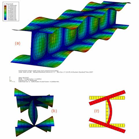
86 Typical FE eigenbuckling results FSM FSM
 Residual stresses: Galambos and Ketter distribution at 30% y Section slenderness varied by thickness (or now)")
87 Initiating nonlinear FE studies Section: W14x233 Stub columns: per SSRC guidelines Material: piece-wise linear elasticplastic with strain hardening (von Mises with isotropic hardening) Element: S4 linear shell Imperections: local mode, magnitude max o b /150 and d/150 (very simplistic) Residual stresses: Galambos and Ketter distribution at 30% y Section slenderness varied by thickness (or now) Engineering Stress (ksi) y = 50 Slope, E =145 Slope, E =29000 u = 65 Slope, E st =720 =0011 Engineering Strain σ t = σ c b t - σ = c y b t + t ( 2 w d t )
88 W14 with reduced lange thickness Force (kips) Displacement (in)
89 1 W14 with reduced lange thickness 08 Pn/Py AISC AISI DSM ABAQUS (y/crb) 05
90 1 W14 with reduced lange thickness and web thickness, in proportion 08 Pn/Py AISC AISI DSM ABAQUS (y/crb) 05
91 Background Direct Strength Method Progress Report 1 talk overview Educational materials on cross-section stability Design approaches or slender cross-sections Progress Report 2 FSM analysis o ALL structural sections (B41+++) Modeling locally slender cross-sections Initiation o nonlinear FE modeling Conclusions
92 Conclusions DSM has something to oer structural steel design potentially simple design expressions or locally slender sections (no elements, no iteration, no eective properties) integrates well with cross-section stability analysis (consistent with DAM or long-term growth o Spec) Q-actor approach in AISC has some limitations (this has been identiied beore), eg, their is good evidence that AISC is overly conservative or unstiened elements FSM o structural steel shapes provides a means to sharpen our pencil on cross-section stability, inal orm could be amenable to conventional design (Table B41 +++) Much work remains, but we are o and running now
Civil. Engineering INELASTIC BENDING CAPACITY IN COLD-FORMED STEEL MEMBERS Annual Stability Conference New Orleans, Louisiana
 Civil Engineering at JOHNS HOPKINS UNIVERSITY at JOHNS HOPKINS UNIVERSITY INELASTIC BENDING CAPACITY IN COLD-FORMED STEEL MEMBERS 2007 Annual Stability Conference New Orleans, Louisiana April 2007 Y.Shifferaw
Direct Strength Design for Cold-Formed Steel Members with Perforations. Progress Report 5 C. Moen and B.W. Schafer AISI-COS Meeting February 2008
 Direct Strength Design for Cold-Formed Steel Members with Perforations Progress Report 5 C. Moen and B.W. Schafer AISI-COS Meeting February 28 outline Objective Summary of past progress Simplified methods
Tutorial 2. SSMA Cee in Compression: 600S F y = 50ksi Objective. A the end of the tutorial you should be able to
 CUFSM 2.5 Tutorial 2 SSMA Cee in Compression: 600S200-33 F y = 50ksi Objective To model a typical Cee stud in compression and determine the elastic critical local buckling load (P crl )and elastic critical
INELASTIC BENDING CAPACITY IN COLD-FORMED STEEL MEMBERS
 INELASTIC BENDING CAPACITY IN COLD-FORMED STEEL MEMBERS report to: American Iron and Steel Institute Committee on Specifications Subcomittee 10 Element Behaviors and Direct Strength Method Subcomittee
Direct Strength Method (DSM) Design Guide
 Design Guide") Direct Strength Method (DSM) Design Guide DESIGN GUIDE CFXX-X January, 6 Committee on Specifications for the Design of Cold-Formed Steel Structural Members American Iron and Steel Institute Preface The
Direct Strength Method (DSM) Design Guide DESIGN GUIDE CFXX-X January, 6 Committee on Specifications for the Design of Cold-Formed Steel Structural Members American Iron and Steel Institute Preface The
Accordingly, the nominal section strength [resistance] for initiation of yielding is calculated by using Equation C-C3.1.
![Accordingly, the nominal section strength [resistance] for initiation of yielding is calculated by using Equation C-C3.1.](/thumbs/89/98617066.jpg "Accordingly, the nominal section strength [resistance] for initiation of yielding is calculated by using Equation C-C3.1.") C3 Flexural Members C3.1 Bending The nominal flexural strength [moment resistance], Mn, shall be the smallest of the values calculated for the limit states of yielding, lateral-torsional buckling and distortional
C3 Flexural Members C3.1 Bending The nominal flexural strength [moment resistance], Mn, shall be the smallest of the values calculated for the limit states of yielding, lateral-torsional buckling and distortional
Cold-Formed Steel Channel Sections with Web Stiffeners Subjected to Local and Distortional Buckling Part II: Parametric Study and Design Rule
 issouri Universit o Science and Technolog Scholars' ine International Specialt Conerence on Cold- Formed Steel Structures (04) - nd International Specialt Conerence on Cold-Formed Steel Structures Nov
Reports RESEARCH REPORT RP00-3 RESEARCH REPORT RP01-1 OCTOBER REVISION 2006 REVISION
 research report A AISI Design Sponsored Approach Resear for ch Complex Reports AISI Sponsored Stiffeners Research Reports RESEARCH REPORT RP00-3 RP01-1 RESEARCH REPORT RP01-1 OCTOBER 2001 2000 REVISION
Direct Strength Method for Steel Deck
 issouri University of Science and Technology Scholars ine AISI-Specifications for the Design of Cold-Formed Steel Structural embers Wei-Wen Yu Center for Cold-Formed Steel Structures 1-1-2015 Direct Strength
Stability of Cold-formed Steel Simple and Lipped Angles under Compression
 Missouri University of Science and Technology Scholars' Mine International Specialty Conference on Cold- Formed Steel Structures (2008) - 19th International Specialty Conference on Cold-Formed Steel Structures
Behavior and Design of Angle Column
 Behavior and Design o Angle Column Ricardo Junqueira Justiniano Instituo Superior Técnico, Universidade de Lisboa Abstract This thesis presents a study on the behavior and design o short to medium single
Reliability-Based Load and Resistance Factor Design (LRFD) Guidelines for Stiffened Panels and Grillages of Ship Structures
 Guidelines for Stiffened Panels and Grillages of Ship Structures") Reliability-Based Load and Resistance actor Design (LRD) Guidelines or Stiened Panels and Grillages o Ship Structures Ibrahim A. Assakka 1, Bilal M. Ayyub 2, Paul E. Hess, III, 3 and Khaled Atua 4 ABSTRACT
Reliability-Based Load and Resistance actor Design (LRD) Guidelines or Stiened Panels and Grillages o Ship Structures Ibrahim A. Assakka 1, Bilal M. Ayyub 2, Paul E. Hess, III, 3 and Khaled Atua 4 ABSTRACT
RESEARCH REPORT RP02-2 MARCH 2002 REVISION Committee on Specifications for the Design of Cold-Formed Steel Structural Members
 research report Web Crippling and Bending Interaction of Cold-Formed Steel Members RESEARCH REPORT RP02-2 MARCH 2002 REVISION 2006 Committee on Specifications for the Design of Cold-Formed Steel Structural
WELDED ALUMINUM ALLOY PLATE GIRDERS SUBJECTED TO SHEAR FORCE
 Advanced Steel Construction Vol. 8, No. 1, pp. 71-94 (2012) 71 WELDED ALUMINUM ALLOY PLATE GIRDERS SUBJECTED TO SHEAR FORCE Feng Zhou 1a, 1b, Ben Young 2,* and Hin-Chung Lam 3 1a Department o Building
Karbala University College of Engineering Department of Civil Eng. Lecturer: Dr. Jawad T. Abodi
 Chapter 04 Structural Steel Design According to the AISC Manual 13 th Edition Analysis and Design of Compression Members By Dr. Jawad Talib Al-Nasrawi University of Karbala Department of Civil Engineering
UNIVERSITY OF AKRON Department of Civil Engineering
 UNIVERSITY OF AKRON Department of Civil Engineering 4300:401-301 July 9, 2013 Steel Design Sample Quiz 2 1. The W10 x 54 column shown has both ends pinned and consists of A992 steel (F y = 50 ksi, F u
An Increase in Elastic Buckling Strength of Plate Girder by the Influence of Transverse Stiffeners
 GRD Journals- Global Research and Development Journal for Engineering Volume 2 Issue 6 May 2017 ISSN: 2455-5703 An Increase in Elastic Buckling Strength of Plate Girder by the Influence of Transverse Stiffeners
research report Design Example for Analytical Modeling of a Curtainwall and Considering the Effects of Bridging (All-Steel Design Approach)
") research report Design Example for Analytical Modeling of a Curtainwall and Considering the Effects of Bridging (All-Steel Design Approach) RESEARCH REPORT RP18- August 018 Committee on Specifications
research report Design Example for Analytical Modeling of a Curtainwall and Considering the Effects of Bridging (All-Steel Design Approach) RESEARCH REPORT RP18- August 018 Committee on Specifications
MODULE C: COMPRESSION MEMBERS
 MODULE C: COMPRESSION MEMBERS This module of CIE 428 covers the following subjects Column theory Column design per AISC Effective length Torsional and flexural-torsional buckling Built-up members READING:
ERRATA. pp Appendix E.6 Add the following paragraph immediately before the last paragraph on p. 334:
 Dear Customer: American Association o State Highwa and Transportation Oicials ERRATA John R. Njord, President Executie Director Utah Department o Transportation John Horsle Executie Director Due to errors
Failure in Flexure. Introduction to Steel Design, Tensile Steel Members Modes of Failure & Effective Areas
 Introduction to Steel Design, Tensile Steel Members Modes of Failure & Effective Areas MORGAN STATE UNIVERSITY SCHOOL OF ARCHITECTURE AND PLANNING LECTURE VIII Dr. Jason E. Charalambides Failure in Flexure!
Critical Strength of steel Girder Web
 American Journal o Engineering Research (AJER) 014 American Journal o Engineering Research (AJER) e-issn : 30-0847 p-issn : 30-0936 Volume-03, Issue-0, pp-09-16 www.ajer.org Research aper Open Access Critical
Sheathing Braced Design of Wall Studs July 2011 Update. for
 Civil Engineering at JOHNS HOPKINS UNIVERSITY Sheathing Braced Design of Wall Studs July 2011 Update www.ce.jhu.edu/bschafer/sheathedwalls for AISI Committee on Framing Standards Design Methods Subcommittee
Comparison of AISI Specification Methods for Members with Single Intermediate Longitudinal Stiffeners
 Missouri University of Science and Technology Scholars' Mine AISI-Specifications for the Design of Cold-Formed Steel Structural Members Wei-Wen Yu Center for Cold-Formed Steel Structures 7-1-006 Comparison
APPLICATIONS OF PURE AND COMBINED BUCKLING MODE CALCULATION OF THIN-WALLED MEMBERS USING THE FINITE ELEMENT METHOD
 SDSS Rio 2010 STABILITY AND DUCTILITY OF STEEL STRUCTURES E. Batista, P. Vellasco, L. de Lima (Eds.) Rio de Janeiro, Brazil, September 8-10, 2010 APPLICATIONS OF PURE AND COMBINED BUCKLING MODE CALCULATION
Unit 18 Other Issues In Buckling/Structural Instability
 Unit 18 Other Issues In Buckling/Structural Instability Readings: Rivello Timoshenko Jones 14.3, 14.5, 14.6, 14.7 (read these at least, others at your leisure ) Ch. 15, Ch. 16 Theory of Elastic Stability
ENCE 455 Design of Steel Structures. III. Compression Members
 ENCE 455 Design of Steel Structures III. Compression Members C. C. Fu, Ph.D., P.E. Civil and Environmental Engineering Department University of Maryland Compression Members Following subjects are covered:
Compression Members. ENCE 455 Design of Steel Structures. III. Compression Members. Introduction. Compression Members (cont.)
") ENCE 455 Design of Steel Structures III. Compression Members C. C. Fu, Ph.D., P.E. Civil and Environmental Engineering Department University of Maryland Compression Members Following subjects are covered:
ENCE 455 Design of Steel Structures III. Compression Members C. C. Fu, Ph.D., P.E. Civil and Environmental Engineering Department University of Maryland Compression Members Following subjects are covered:
3.5 Analysis of Members under Flexure (Part IV)
") 3.5 Analysis o Members under Flexure (Part IV) This section covers the ollowing topics. Analysis o a Flanged Section 3.5.1 Analysis o a Flanged Section Introduction A beam can have langes or lexural eiciency.
3.5 Analysis o Members under Flexure (Part IV) This section covers the ollowing topics. Analysis o a Flanged Section 3.5.1 Analysis o a Flanged Section Introduction A beam can have langes or lexural eiciency.
The achievable limits of operational modal analysis. * Siu-Kui Au 1)
") The achievable limits o operational modal analysis * Siu-Kui Au 1) 1) Center or Engineering Dynamics and Institute or Risk and Uncertainty, University o Liverpool, Liverpool L69 3GH, United Kingdom 1)
The achievable limits o operational modal analysis * Siu-Kui Au 1) 1) Center or Engineering Dynamics and Institute or Risk and Uncertainty, University o Liverpool, Liverpool L69 3GH, United Kingdom 1)
RESOLUTION MSC.362(92) (Adopted on 14 June 2013) REVISED RECOMMENDATION ON A STANDARD METHOD FOR EVALUATING CROSS-FLOODING ARRANGEMENTS
 (Adopted on 14 June 2013) REVISED RECOMMENDATION ON A STANDARD METHOD FOR EVALUATING CROSS-FLOODING ARRANGEMENTS") (Adopted on 4 June 203) (Adopted on 4 June 203) ANNEX 8 (Adopted on 4 June 203) MSC 92/26/Add. Annex 8, page THE MARITIME SAFETY COMMITTEE, RECALLING Article 28(b) o the Convention on the International
(Adopted on 4 June 203) (Adopted on 4 June 203) ANNEX 8 (Adopted on 4 June 203) MSC 92/26/Add. Annex 8, page THE MARITIME SAFETY COMMITTEE, RECALLING Article 28(b) o the Convention on the International
Objectives. By the time the student is finished with this section of the workbook, he/she should be able
 FUNCTIONS Quadratic Functions......8 Absolute Value Functions.....48 Translations o Functions..57 Radical Functions...61 Eponential Functions...7 Logarithmic Functions......8 Cubic Functions......91 Piece-Wise
Karbala University College of Engineering Department of Civil Eng. Lecturer: Dr. Jawad T. Abodi
 Chapter 05 Structural Steel Design According to the AISC Manual 13 th Edition Analysis and Design of Beams By Dr. Jawad Talib Al-Nasrawi University of Karbala Department of Civil Engineering 71 Introduction
Design criteria for Fiber Reinforced Rubber Bearings
 Design criteria or Fiber Reinorced Rubber Bearings J. M. Kelly Earthquake Engineering Research Center University o Caliornia, Berkeley A. Calabrese & G. Serino Department o Structural Engineering University
A Design Procedure for Lipped Channel Flexural Members
 Missouri University of Science and Technology Scholars' Mine International Specialty Conference on Cold- Formed Steel Structures (1994) - 12th International Specialty Conference on Cold-Formed Steel Structures
DESIGN OF BUCKLING RESISTANCE OF COMPRESSED HSS - CHANNELS
 DESIGN OF BUCKLING RESISTANCE OF COMPRESSED HSS - CHANNELS ABSTRACT Asko Talja Technical Research Centre of Finland (VTT) Laboratory of Structural Engineering Kemistintie 3 SF- 02150 ESPOO FINLAND Rakenteiden
Timber and Steel Design. Lecture 7 - B E A M. Introduction to. Floor Framing System Bending Stresses Compact Sections Lateral Support of Beams
 Timer and Steel Design Lecture 7 - Introduction to B E A M loor raming Sstem Bending Stresses Compact Sections Lateral Support of Beams S U R A N A R E E UNIVERSITY O TECHNOLOGY Mongkol JIRAVACHARADET
This procedure covers the determination of the moment of inertia about the neutral axis.
 327 Sample Problems Problem 16.1 The moment of inertia about the neutral axis for the T-beam shown is most nearly (A) 36 in 4 (C) 236 in 4 (B) 136 in 4 (D) 736 in 4 This procedure covers the determination
NUMERICAL ANALYSES OF COLD-FORMED THIN-WALLED SECTIONS WITH CONSIDERATION OF IMPERFECTIONS DUE TO THE PRODUCTION PROCESS
 Advanced Steel Construction Vol. 5, No., pp. 151-163 (009) 151 NUMERICAL ANALYSES OF COLD-FORMED THIN-WALLED SECTIONS WITH CONSIDERATION OF IMPERFECTIONS DUE TO THE PRODUCTION PROCESS Albrecht Gehring
5 Compression Members
 5 Compression Members 5.1 GENERAL REMARKS Similar to the heavy hot-rolled steel sections, thin-walled cold-formed steel compression members can be used to carry a compressive load applied through the centroid
Manufacturing Remaining Stresses in Truck Frame Rail's Fatigue Life Prediction
 Manuacturing Remaining Stresses in Truck Frame Rail's Fatigue Lie Prediction Claudiomar C. Cunha & Carlos A. N. Dias MSX International & Department o Naval Engineering EPUSP/USP/Brazil Department o Mechanical
8.3 Design of Base Plate for Thickness
 8.3 Design o Base Plate or Thickness 8.3.1 Design o base plate or thickness (Elastic Design) Upto this point, the chie concern has been about the concrete oundation, and methods o design have been proposed
Ultimate Shear Resistance of Plate Girders Part 2- Höglund Theory Ahmed S. Elamary
 World Academy o Science, Engineering and Technology International Journal o Ciil and Enironmental Engineering Vol:7, No:, 03 Ultimate Shear Resistance o Plate Girders Part - Höglund Theory Ahmed S. Elamary
CHAPTER II EXPERIMENTAL INVESTIGATION
 CHAPTER II EXPERIMENTAL INVESTIGATION 2.1 SCOPE OF TESTING The objective of this research is to determine the force distribution between the column web and stiffener when the column flanges are subjected
General Comparison between AISC LRFD and ASD
 General Comparison between AISC LRFD and ASD 1 General Comparison between AISC LRFD and ASD 2 AISC ASD and LRFD AISC ASD = American Institute of Steel Construction = Allowable Stress Design AISC Ninth
APPENDIX 1 MODEL CALCULATION OF VARIOUS CODES
 163 APPENDIX 1 MODEL CALCULATION OF VARIOUS CODES A1.1 DESIGN AS PER NORTH AMERICAN SPECIFICATION OF COLD FORMED STEEL (AISI S100: 2007) 1. Based on Initiation of Yielding: Effective yield moment, M n
Local Buckling. Local Buckling in Columns. Buckling is not to be viewed only as failure of the entire member
 Local Buckling MORGAN STATE UNIVERSITY SCHOOL OF ARCHITECTURE AND PLANNING LECTURE V Dr. Jason E. Charalamides Local Buckling in Columns Buckling is not to e viewed only as failure of the entire memer
Direct Strength Method of Design for Shear of Cold-formed Channels Based on a Shear Signature Curve
 Missouri University of Science and Technology Scholars' Mine International Specialty Conference on Cold- Formed Steel Structures (2012) - 21st International Specialty Conference on Cold-Formed Steel Structures
Bond strength model for interfaces between nearsurface mounted (NSM) CFRP strips and concrete
 CFRP strips and concrete") University o Wollongong Research Online Faculty o Engineering and Inormation Sciences - Papers: Part A Faculty o Engineering and Inormation Sciences 2014 Bond strength model or interaces between nearsurace
University o Wollongong Research Online Faculty o Engineering and Inormation Sciences - Papers: Part A Faculty o Engineering and Inormation Sciences 2014 Bond strength model or interaces between nearsurace
RELIABILITY ANALYSIS OF TYPICAL COLD-FORMED STEEL BEAMS SECTIONS
 RELIABILITY ANALYSIS OF TYPICAL COLD-FORMED STEEL BEAMS SECTIONS Raylza Santos da Silva Campos André Luis Riqueira Brandão raylzacampos@gmail.com andreriqueira@uniei.edu.br Universidade Federal de Itajubá
Least-Squares Spectral Analysis Theory Summary
 Least-Squares Spectral Analysis Theory Summary Reerence: Mtamakaya, J. D. (2012). Assessment o Atmospheric Pressure Loading on the International GNSS REPRO1 Solutions Periodic Signatures. Ph.D. dissertation,
CHAPTER 2 LITERATURE REVIEW
 8 CHAPTER 2 LITERATURE REVIEW 2.1 GENERAL A brief review of the research carried out during the past years related to the behaviour of bolted steel angle tension members is presented herewith. Literature
HYBRID STEEL PLATE GIRDERS SUBJECTED TO PATCH LOADING
 SDSS Rio 21 STABILITY AND DUCTILITY OF STEEL STRUCTURES E. Batista, P. Vellasco, L. de Lima (Eds.) Rio de Janeiro, Brazil, September 8-1, 21 HYBRID STEEL PLATE GIRDERS SUBJECTED TO PATCH LOADING Rolando
(Round up to the nearest inch.)
") Assignment 10 Problem 5.46 LRFD First, select the lightest weight W14 column. Use the recommended design value for K for the pinned-fixed support condition specified (ref. Commentary, Appendix 7, AISC
Assignment 10 Problem 5.46 LRFD First, select the lightest weight W14 column. Use the recommended design value for K for the pinned-fixed support condition specified (ref. Commentary, Appendix 7, AISC
INFLUENCE OF FLANGE STIFFNESS ON DUCTILITY BEHAVIOUR OF PLATE GIRDER
 International Journal of Civil Structural 6 Environmental And Infrastructure Engineering Research Vol.1, Issue.1 (2011) 1-15 TJPRC Pvt. Ltd.,. INFLUENCE OF FLANGE STIFFNESS ON DUCTILITY BEHAVIOUR OF PLATE
Flange Curling in Cold Formed Profiles
 Downloaded from orbit.dtu.dk on: Sep 4, 28 Flange Curling in Cold Formed Profiles Jönsson, Jeppe; Ramonas, Gediminas Published in: Proceedings of Nordic Steel Construction Conference 22 Publication date:
Torsional Analysis of
 Steel Design Guide Series Torsional Analysis of Structured Steel Members Steel Design Guide Series Torsional Analysis of Structural Steel Members Paul A. Seaburg, PhD, PE Head, Department of Architectural
Heat transfer studies for a crystal in a synchrotron radiation beamline
 Sādhanā Vol. 34, Part 2, April 2009, pp. 243 254. Printed in India Heat transer studies or a crystal in a synchrotron radiation beamline A K SINHA Synchrotron Utilisation and Materials Research Division,
Evaluation of Scantlings of Corrugated Transverse Watertight Bulkheads in Non-CSR Bulk Carriers Considering Hold Flooding
 (1997) (Rev.1 1997) (Rev.1.1 Mar 1998 /Corr.1) (Rev. Sept 000) (Rev.3 eb 001) (Rev.4 Nov 001) (Rev.5 July 003) (Rev.6 July 004) (Rev.7 eb 006) (Corr.1 Oct 009) (Rev.8 May 010) (Rev.9 Apr 014) Evaluation
of I Section Members
 IMPROVED DESIGN ASSESSMENT OF LTB OF I-SECTION MEMBERS VIA MODERN COMPUTATIONAL METHODS Improved Design Assessment of LTB of I Section Members Donald W. White (with credits to Dr. Woo Yong Jeong & Mr.
Keywords: creep, damage, finite element analysis, FSRF, low-cycle fatigue, type 316 steel, weldment
 --- 1 --- Application o the linear matching method to eep-atigue ailure analysis o uciorm weldment manuactured o the austenitic steel AISI type 316N(L) Yevgen Gorash and Haoeng Chen Department o Mechanical
SECTION 7 DESIGN OF COMPRESSION MEMBERS
 SECTION 7 DESIGN OF COMPRESSION MEMBERS 1 INTRODUCTION TO COLUMN BUCKLING Introduction Elastic buckling of an ideal column Strength curve for an ideal column Strength of practical column Concepts of effective
Design of Beams (Unit - 8)
") Design of Beams (Unit - 8) Contents Introduction Beam types Lateral stability of beams Factors affecting lateral stability Behaviour of simple and built - up beams in bending (Without vertical stiffeners)
Design of Beams (Unit - 8) Contents Introduction Beam types Lateral stability of beams Factors affecting lateral stability Behaviour of simple and built - up beams in bending (Without vertical stiffeners)
SUMMARY FOR COMPRESSION MEMBERS. Determine the factored design loads (AISC/LRFD Specification A4).
.") SUMMARY FOR COMPRESSION MEMBERS Columns with Pinned Supports Step 1: Step : Determine the factored design loads (AISC/LRFD Specification A4). From the column tables, determine the effective length KL using
SUMMARY FOR COMPRESSION MEMBERS Columns with Pinned Supports Step 1: Step : Determine the factored design loads (AISC/LRFD Specification A4). From the column tables, determine the effective length KL using
COLUMNS: BUCKLING (DIFFERENT ENDS)
") COLUMNS: BUCKLING (DIFFERENT ENDS) Buckling of Long Straight Columns Example 4 Slide No. 1 A simple pin-connected truss is loaded and supported as shown in Fig. 1. All members of the truss are WT10 43
COLUMNS: BUCKLING (DIFFERENT ENDS) Buckling of Long Straight Columns Example 4 Slide No. 1 A simple pin-connected truss is loaded and supported as shown in Fig. 1. All members of the truss are WT10 43
FASTENER SPACING STUDY OF COLD-FORMED STEEL WALL STUDS USING FINITE STRIP AND FINITE ELEMENT METHODS
 FASTENER SPACING STUDY OF COLD-FORMED STEEL WALL STUDS USING FINITE STRIP AND FINITE ELEMENT METHODS RESEARCH REPORT Brian Post Dept. of Civil Engineering Johns Hopins University December 202 .0 INTRODUCTION
BUCKLING MODE CLASSIFICATION OF MEMBERS WITH OPEN THIN-WALLED CROSS-SECTIONS
 CIMS 4 Fourth International Conference on Coupled Instabilities in Metal Structures Rome, Italy, 27-29 September, 24 BUCKLING MODE CLASSIFICATION OF MEMBERS WITH OPEN THIN-WALLED CROSS-SECTIONS S. ÁDÁNY,
NUMERICAL EVALUATION OF THE ROTATIONAL CAPACITY OF STEEL BEAMS AT ELEVATED TEMPERATURES
 8 th GRACM International Congress on Computational Mechanics Volos, 12 July 15 July 2015 NUMERICAL EVALUATION OF THE ROTATIONAL CAPACITY OF STEEL BEAMS AT ELEVATED TEMPERATURES Savvas Akritidis, Daphne
APPENDIX A Thickness of Base Metal
 APPENDIX A Thickness of Base Metal For uncoated steel sheets, the thickness of the base metal is listed in Table A.1. For galvanized steel sheets, the thickness of the base metal can be obtained by subtracting
PLATE BUCKLING ACCORDING TO EUROCODE 3. COMPARISON OF THE EFFECTIVE WIDTH METHOD AND THE REDUCED STRESS METHOD
 SDSS Rio 00 STABILITY AND DUCTILITY OF STEEL STRUCTURES E. Batista P. Vellasco L. de Lima (s.) Rio de Janeiro Brail September 8-0 00 PLATE BUCKLING ACCORDING TO EUROCODE 3. COMPARISON OF THE EFFECTIVE
Flexural-Torsional Buckling of General Cold-Formed Steel Columns with Unequal Unbraced Lengths
 Proceedings of the Annual Stability Conference Structural Stability Research Council San Antonio, Texas, March 21-24, 2017 Flexural-Torsional Buckling of General Cold-Formed Steel Columns with Unequal
TORSION INCLUDING WARPING OF OPEN SECTIONS (I, C, Z, T AND L SHAPES)
") Page1 TORSION INCLUDING WARPING OF OPEN SECTIONS (I, C, Z, T AND L SHAPES) Restrained warping for the torsion of thin-wall open sections is not included in most commonly used frame analysis programs. Almost
Page1 TORSION INCLUDING WARPING OF OPEN SECTIONS (I, C, Z, T AND L SHAPES) Restrained warping for the torsion of thin-wall open sections is not included in most commonly used frame analysis programs. Almost
Reliability assessment on maximum crack width of GFRPreinforced
 Fourth International Conerence on FRP Composites in Civil Engineering (CICE2008) 22-24July 2008, Zurich, Switzerland Reliability assessment on maximum crack width o GFRPreinorced concrete beams Z. He and
10/14/2011. Types of Shear Failure. CASE 1: a v /d 6. a v. CASE 2: 2 a v /d 6. CASE 3: a v /d 2
 V V Types o Shear Failure a v CASE 1: a v /d 6 d V a v CASE 2: 2 a v /d 6 d V a v CASE 3: a v /d 2 d V 1 Shear Resistance Concrete compression d V cz = Shear orce in the compression zone (20 40%) V a =
RATIONAL FUNCTIONS. Finding Asymptotes..347 The Domain Finding Intercepts Graphing Rational Functions
 RATIONAL FUNCTIONS Finding Asymptotes..347 The Domain....350 Finding Intercepts.....35 Graphing Rational Functions... 35 345 Objectives The ollowing is a list o objectives or this section o the workbook.
Longitudinal Strength Standard for Container Ships
 (June 05) Longitudinal Strength Standard or Container Ships. General.. Application... Application This UR applies to the ollowing types o steel ships with a length L o 90 m and greater and operated in
twenty one concrete construction: materials & beams ELEMENTS OF ARCHITECTURAL STRUCTURES: FORM, BEHAVIOR, AND DESIGN DR. ANNE NICHOLS SPRING 2014
 ELEMENTS OF ARCHITECTURAL STRUCTURES: FORM, BEHAVIOR, AND DESIGN DR. ANNE NICHOLS SPRING 2014 lecture twenty one concrete construction: http:// nisee.berkeley.edu/godden materials & beams Concrete Beams
Singly Symmetric Combination Section Crane Girder Design Aids. Patrick C. Johnson
 Singly Symmetric Combination Section Crane Girder Design Aids by Patrick C. Johnson PCJohnson@psu.edu The Pennsylvania State University Department of Civil and Environmental Engineering University Park,
Numerical Approach for Torsion Properties of Built-Up Runway Girders
 Tamkang Journal of Science and Engineering, Vol. 12, No. 4, pp. 381 389 (2009) 381 Numerical Approach for Torsion Properties of Built-Up Runway Girders Wei T. Hsu, Dung M. Lue* and Bor T. Hsiao Department
APPENDIX D COMPARISON OF CURVED STEEL I-GIRDER BRIDGE DESIGN SPECIFICATIONS
 APPENIX COMPARISON O CURVE STEEL I-GIRER BRIGE ESIGN SPECIICATIONS (This page is intentionally left blank.) TABLE O CONTENTS LIST O IGURES... -iv LIST O TABLES... -vi 1 OBJECTIVE... -1 METHOOLOGY... -1
Finite element modeling incorporating nonlinearity of material behavior based on the fib Model Code 2010
 Peer-reviewed & Open access journal www.academicpublishingplatorms.com Finite element modeling incorporating non-linearity o material behavior ATI - Applied Technologies & Innovations Volume 5 Issue November
It s a bird it s a plane it s Super Table! F y = 50 ksi F u = 65 ksi ASD LRFD ASD LRFD
 It s a bird it s a plane it s Super Table! steelwise ONE-STOP SHOP BY ABBAS AMINMANSOUR, PhD WHAT IF THERE WAS a table that could be directly used for designing tension members, compression members, flexural
Design of Steel Structures Dr. Damodar Maity Department of Civil Engineering Indian Institute of Technology, Guwahati
 Design of Steel Structures Dr. Damodar Maity Department of Civil Engineering Indian Institute of Technology, Guwahati Module - 6 Flexural Members Lecture 5 Hello today I am going to deliver the lecture
Supporting Information for: Flexible Energy Conversion
 Supporting Inormation or: Piezoelectric Nanoribbons Printed onto Rubber or Flexible Energy Conversion Yi Qi, Noah T. Jaeris, Kenneth Lyons, Jr., Christine M. Lee, Habib Ahmad, Michael C. McAlpine *, Department
Load and resistance factor design of cold-formed steel: Calibration of the AISI design provisions
 Missouri University of Science and Technology Scholars' Mine Center for Cold-Formed Steel Structures Library Wei-Wen Yu Center for Cold-Formed Steel Structures 2-1-1988 Load and resistance factor design
twenty steel construction: columns & tension members ARCHITECTURAL STRUCTURES: FORM, BEHAVIOR, AND DESIGN DR. ANNE NICHOLS FALL 2013 lecture
 ARCHITECTURAL STRUCTURES: FORM, BEHAVIOR, AND DESIGN DR. ANNE NICHOLS Cor-Ten Steel Sculpture By Richard Serra Museum of Modern Art Fort Worth, TX (AISC - Steel Structures of the Everyday) FALL 2013 lecture
OBSERVER/KALMAN AND SUBSPACE IDENTIFICATION OF THE UBC BENCHMARK STRUCTURAL MODEL
 OBSERVER/KALMAN AND SUBSPACE IDENTIFICATION OF THE UBC BENCHMARK STRUCTURAL MODEL Dionisio Bernal, Burcu Gunes Associate Proessor, Graduate Student Department o Civil and Environmental Engineering, 7 Snell
NUMERICAL ASSESSMENT OF REINFORCED CONCRETE MEMBERS RETROFITTED WITH FIBER REINFORCED POLYMER FOR RESISTING BLAST LOADING
 NUMERICAL ASSESSMENT OF REINFORCED CONCRETE MEMBERS RETROFITTED WITH FIBER REINFORCED POLYMER FOR RESISTING BLAST LOADING By GRAHAM LONG A THESIS PRESENTED TO THE GRADUATE SCHOOL OF THE UNIVERSITY OF FLORIDA
CHAPTER 1: INTRODUCTION. 1.1 Inverse Theory: What It Is and What It Does
 Geosciences 567: CHAPTER (RR/GZ) CHAPTER : INTRODUCTION Inverse Theory: What It Is and What It Does Inverse theory, at least as I choose to deine it, is the ine art o estimating model parameters rom data
Strain and Stress Measurements with a Two-Dimensional Detector
 Copyright ISSN (C) 97-, JCPDS-International Advances in X-ray Centre Analysis, or Volume Diraction 4 Data 999 5 Strain and Stress Measurements with a Two-Dimensional Detector Baoping Bob He and Kingsley
Gaussian Process Regression Models for Predicting Stock Trends
 Gaussian Process Regression Models or Predicting Stock Trends M. Todd Farrell Andrew Correa December 5, 7 Introduction Historical stock price data is a massive amount o time-series data with little-to-no
POST-BUCKLING CAPACITY OF BI-AXIALLY LOADED RECTANGULAR STEEL PLATES
 POST-BUCKLING CAPACITY OF BI-AXIALLY LOADED RECTANGULAR STEEL PLATES Jeppe Jönsson a and Tommi H. Bondum b a,b DTU Civil Engineering, Technical University of Denmark Abstract: Results from a detailed numerical
The Influence of a Weld-Affected Zone on the Compressive and Flexural Strength of Aluminum Members
 Bucknell University Bucknell Digital Commons Honors Theses Student Theses 2013 The Influence of a Weld-Affected Zone on the Compressive and Flexural Strength of Aluminum Members Shengduo Du sd034@bucknell.edu
Professor, Institute of Engineering Mechanics, Harbin. China 2. Ph.D Student, Institute of Engineering Mechanics, Harbin. China 3
 The 14 th World Conerence on Earthquake Engineering COMPARISON OF FRP-RETROFITTING STRATEGIES IN CHINESE AND ITALIAN CODES J. W. DAI 1, Y.R. WANG 2, B. JIN 1, 3, D.F.ZU 4, Silvia Alessandri 5, Giorgio
The Application of Reliability Methods in the Design of Tophat Stiffened
 The Application o Reliability Methods in the Design o Tophat Stiened Composite Panels under In-plane Loading Yang N. (1)() & Das P. K., () (1) Harbin Engineering University, China ()University o Strathclyde,
CE 312 Structural Analysis and Design Sessional-I (Lab Manual)
") CE Structural Analysis and Design Sessional-I (ab Manual) Department of Civil Engineering Ahsanullah University of Science and Technology December, 07 Preface Structural Analysis and Design Sessional-I
CE Structural Analysis and Design Sessional-I (ab Manual) Department of Civil Engineering Ahsanullah University of Science and Technology December, 07 Preface Structural Analysis and Design Sessional-I
Chapter 6 Reliability-based design and code developments
 Chapter 6 Reliability-based design and code developments 6. General Reliability technology has become a powerul tool or the design engineer and is widely employed in practice. Structural reliability analysis
Plastic mechanism analysis of CHS stub columns strengthened using CFRP
 Plastic mechanism analis o CHS stub columns strengthened using CFRP M. Elchalakani School o rchitectural, Civil and Mechanical Engineering, Victoria University, Melbourne, ustralia M.R. Bambach Department
RELIABILITY OF BURIED PIPELINES WITH CORROSION DEFECTS UNDER VARYING BOUNDARY CONDITIONS
 REIABIITY OF BURIE PIPEIES WITH CORROSIO EFECTS UER VARYIG BOUARY COITIOS Ouk-Sub ee 1 and ong-hyeok Kim 1. School o Mechanical Engineering, InHa University #53, Yonghyun-ong, am-ku, Incheon, 40-751, Korea
Life Prediction Under Multiaxial Fatigue
 Lie Prediction Under Multiaxial Fatigue D. Ramesh and M.M. Mayuram Department o Mechanical Engineering Indian Institute o Technology, Madras Chennai-600 036 (India) e-mail: mayuram@iitm.ac.in ABSTRACT