NUMERICAL ASSESSMENT OF REINFORCED CONCRETE MEMBERS RETROFITTED WITH FIBER REINFORCED POLYMER FOR RESISTING BLAST LOADING
|
|
|
- Lilian Glenn
- 5 years ago
- Views:
Transcription
1 NUMERICAL ASSESSMENT OF REINFORCED CONCRETE MEMBERS RETROFITTED WITH FIBER REINFORCED POLYMER FOR RESISTING BLAST LOADING By GRAHAM LONG A THESIS PRESENTED TO THE GRADUATE SCHOOL OF THE UNIVERSITY OF FLORIDA IN PARTIAL FULFILLMENT OF THE REQUIREMENTS FOR THE DEGREE OF MASTER OF ENGINEERING UNIVERSITY OF FLORIDA
2 2012 Graham Long 2
3 To my amily and riends 3
4 ACKNOWLEDGMENTS I would like to express my sincere gratitude to Dr. Theodor Krauthammer or his advice and direction acilitating the completion o this research. I would also like to thank Dr. Serdar Astarlioglu or his support in the completion o this research. Finally, I would like to thank the Canadian Armed Forces and 1 ESU (1 st Engineer Support Unit) or providing me with the opportunity to complete my graduate studies in structural engineering. 4
5 TABLE OF CONTENTS page ACKNOWLEDGMENTS... 4 LIST OF TABLES... 7 LIST OF FIGURES... 8 LIST OF ABBREVIATIONS ABSTRACT CHAPTER 1 INTRODUCTION Problem Statement Objective and Scope Research Signiicance BACKGROUND LITERATURE REVIEW Dynamic Structural Analysis Suite (DSAS) Blast Loading Materials Concrete Compressive stress-strain curve Tensile stress-strain curve Steel Fiber Reinorced Polymers (FRP) Dynamic Analysis Equivalent SDOF System Equivalent mass Equivalent loading unction Resistance Function Numerical Integration Flexural Behavior Diagonal Shear Behavior Rate Eects Fiber Reinorced Polymers FRP Flexural Behavior FRP Shear Behavior FRP Rate Eects FRP Size Eects Debonding Behavior Shear stress
6 Normal stress Mixed mode initiation Eective bond length Ultimate bond strength Load-Impulse (P-I) Diagrams METHODOLOGY Structural Overview Debonding Behavior DSAS Overall Algorithm ANALYSIS Material Model Validation Debonding Validation Dynamic loading Parametric Study FRP Ultimate Strength FRP Elastic Modulus FRP Thickness FRP Width SUMMARY AND CONCLUSIONS Limitations Future Development /Recommendations General Conclusions REFERENCE LIST BIOGRAPHICAL SKETCH
7 LIST OF TABLES Table page 4-1 Beam material properties or experimental test case DSAS inputs or material model veriication Peak results o unstrengthen static loading case Peak results o FRP strengthened static loading case Material data or parametric case studies
8 LIST OF FIGURES Figure page 2-1 Free ield pressure time variation Modiied Hognestad stress-strain curve or concrete in compression Conined concrete stress strain curve Tensile stress strain curve or reinorced concrete Steel Stress-strain curve model Deormation proile or a beam SDOF inelastic resistance model Stress strain diagram or reinorced concrete beam Shear reduction model Section orces or FRP reinorced concrete beam Typical response unctions Test beam rom study Comparison o debonding process DSAS debonding algorithm Overall DSAS algorithm Validation o the material model o DSAS Load-displacement curve or validation o the debonding model in DSAS Moment-curvature model or validation o the debonding model in DSAS Time-displacement response to blast loading case Pressure-impulse curve under uniorm blast loading Eect o FRP Yield Strength Eect o FRP Modulus o Elasticity Eect o FRP thickness
9 4-9 Eect o FRP width
10 LIST OF ABBREVIATIONS A ci A si b c b c C d si Area o concrete at each layer Area o steel at each layer Concrete width FRP width Neutral axis depth Damping coeicient Depth o steel layer D Nominal diameter o hoops D Nominal diameter o longitudinal compression reinorcement E ad E c Enh c Enh ct Enh s E E s F Adhesive modulus o elasticity Elastic modulus o concrete Concrete enhancement actor in compression Concrete enhancement actor in tension Steel enhancement actor FRP modulus o elasticity Steel modulus o elasticity Force c Compressive strength o concrete ci F ci F e t s Stress o concrete layer Concrete layer orces Equivalent Force Tensile strength Steel stress 10
11 si F si u y Stress o steel layer Steel layer orces Ultimate steel stress Steel yield stress y Yield stress o the hoops/stirrups G G n G s G T h FRP interacial racture energy Normal interacial racture energy Shear interacial racture energy Total interacial racture energy Concrete section depth H Average core dimension o the conined concrete compression area i s K K e K L K m l L e L b M m ci M e M l Impulse Stiness Resistance actor Load actor Mass actor Length Eective bond length Bond length Mass Concrete layer moment Equivalent mass Ultimate moment capacity due only to lexure 11
12 M n m si M t M u Pso P u t ad t t o R R m R e s s n s n s s s s s so SRF u 1 u 2 u u& Moment at mid-span Steel layer moment Total mass Ultimate moment capacity due only to shear Incident pressure Bond strength Thickness o adhesive layer Thickness o FRP Time o positive Phase Resistance unction Maximum resistance Equivalent resistance unction Hoop spacing Normal stress slip Slip at maximum normal stress Shear stress slip Slip at inal debonding Slip at maximum shear stress Shear reduction actor Axial displacement o member Axial displacement o debonded section Displacement Velocity 12
13 u& & w w 1 w 2 Y 1 Y 2 x z i β β l β w Δ δ ε ε c ε s ε sh ε ε& ε& s Acceleration Uniormly distributed load Vertical displacement o member Vertical displacement o debonded section Distance rom debonded interace to member neutral axis Distance rom debonded interace to debonded section neutral axis Position Depth o concrete layer Newmark-Beta constant Eective bond length actor Bond width ratio actor Increment space Delection Total Strain Concrete Strain Steel strain Strain hardening in steel Final strain in steel Strain rate Quasi-static strain rate ρ Web reinorcement ratio ϕ Shape unction α bl Blast loading decay coeicient 13
14 σ n Normal shear stress τ Interacial shear stress τ max Max interacial shear stress 14
15 Abstract o Thesis Presented to the Graduate School o the University o Florida in Partial Fulillment o the Requirements or the Degree o Master o Engineering NUMERICAL ASSESSMENT OF REINFORCED CONCRETE MEMBERS RETROFITTED WITH FRP FOR RESISTING BLAST LOADING Chair: Theodore Krauthammer Major: Civil Engineering By Graham Long May 2012 The use o iber reinorced polymers or the retroit o existing structures is a common practice in blast protection. The tools used to assess the behavior o structures have become more reined allowing or precise modeling o reinorced members retroitted with iber reinorced polymers (FRP). However, many o these tools require extensive computational power that is oten time consuming. This study aims to adapt an existing expedient dynamic analysis assessment tool in order to account or the behavior o reinorced concrete members retroitted with FRP or lexural enhancement. FRP retroits have been shown to increase the capacity o the members under severe loading conditions. However, the strength associated with the FRP layer is not always able to ully develop due to the debonding behavior between the two suraces. The model will seek to capture this behavior by employing racture mechanics along the bonded interace. The results o the modeling tool will be validated by comparing them to those o inite element analysis programs as well as available experimental test data. An additional parametric study will be conducted to evaluate the models ability to capture the bond behavior when adjusting the properties associated with the FRP. 15
16 CHAPTER 1 INTRODUCTION Problem Statement The vulnerability o many existing structures has been demonstrated by the various incidents over the last hal century. Many o these structures were not designed to withstand severe loading due to an explosive loading incidents. As a result, there has been a requirement to increase the blast resistance or other critical inrastructure systems in order to preserve lie and operations. While extensive studies were conducted on the various means or retroitting existing structures under normal service and seismically-induced loading, it is only within the last two decades that the research has expanded to include severe short duration loading cases. The choice on which method to use oten depends on a variety o actors. While dierent acilities will have dierent governing actors, the actor that continually is expressed is the cost to eectiveness ratio. For this reason, the use o externally bonded iber reinorced polymer (FRP) strips or mats have been identiied as a suitable option due to its high strength to weight ratio. In addition, the ease o application allows or the retroit to be completed in a timely manner. The employment o FRP along the tension ace allows or an initial increase in beam lexural strength while reducing the delection. However, the eectiveness o the FRP retroit is limited by the bond strength. In most cases, the FRP will debond rom the beam beore the it reaches its ultimate strength. It is thereore important to model the bond and the debonding behavior in order to accurately determine the eectiveness o a retroit. 16
17 Extensive design calculations are oten required or determining the ull eect o these severe load cases on structural members and the means to counteract the eect. The use o an advanced inite element method is computationally expensive and may not be suitable in time sensitive situations. Conversely, the use o design guidelines provides methods that do not require extensive analysis to design against speciic threats but may not apply to all cases. In addition, these guidelines are oten conservative and may produce results that may not be cost eicient due to conservative limits. Thereore, an approach that combines a high level o accuracy as well as utilizes a simpliied analysis method to minimize computational time is required to produce accurate results when time is limited. Dynamic Structural Analysis Suite (DSAS) is a computer program that has been under development or many years and has had extensive research completed on reinorced concrete structural members. However, retroitting these structures with new composite materials has not been incorporated into that research and urther work needs to be done to develop an expedient algorithm to account or these new methods. Objective and Scope The objective o this research project is to develop an algorithm that is both computationally expedient and suiciently accurate or the purpose o analyzing reinorced concrete beams retroitted with externally bonded iber reinorced polymer (FRP) strips subjected to severe short dynamic loading. The research project will be completed in the ollowing steps: Develop an algorithm to evaluate the lexural and deormation responses o reinorced concrete members retroitted with externally bonded iber reinorced polymer strips on the tension ace o the member and implement this algorithm as a new module in DSAS. 17
18 Validate the algorithm model in and the results obtained in DSAS to available experimental data. Complete a parametric study using DSAS to ully understand the eect o FRP layer on reinorced concrete members subjected to severe short duration load cases, by comparing their behavior with and without the retroit. Various thicknesses and strengths o the FRP layer will also be examined to determine the eect on debonding and lexural enhancement. Research Signiicance The algorithm to be developed in this study will be incorporated into the computer code, DSAS, in order urther develop the resistance unction o the components. DSAS will then have the capability to assess the response o reinorced concrete retroitted with externally bonded iber reinorced polymer strips. 18
19 CHAPTER 2 BACKGROUND LITERATURE REVIEW This chapter will provide a review o the concepts and studies associated with the behavior o reinorced concrete members retroitted with FRP. The topics will include a look at the structural analysis process employed by the Dynamic Structural Analysis Suite as well as the characteristics and behaviors associated with externally bonded FRP materials. The material is based on a review o recent studies and publications in the ield o protective structures and iber reinorced polymer. Dynamic Structural Analysis Suite (DSAS) DSAS is a multiunctional program that is capable o modeling the response o a wide range o structural components under both static and dynamic loads (Chee et al. 2008; Tran et al. 2009; Morency et al. 2010). It has the capability to perorm timehistory and load-impulse (P-I) analyses by employing accurate resistance unctions that can be derived or the various structural elements in its library. This program utilizes a combination o advanced ully-nonlinear and Physics-based structural behavioral models or expedient structural behavior computations. Blast Loading Blast loading is a shockwave caused by a sudden release o energy rom an explosive device. In the case o an air blast at ground level, the shockwave is simultaneously relected o the ground and the wave expands out in a hemispherical coniguration. The loading produced rom this shockwave can be assumed to be uniormly distributed over the entire structural member, except when the point o initiation is extremely close to the structure. In which case, advanced computational luid dynamic (CFD) simulations are required to determine the complicated interaction 19
20 between the blast wave and a structure. The loading time history can be illustrated using the ree ield pressure-time variation obtained rom TM (1986) by means o Krauthammer (2008) and is illustrated in Figure 2-1. Loading due blast is characterized by an initial peak overpressure that decays over time based on a decay coeicient. The loading will consist o two phases, positive and negative. Loading due to a blast and impact is characterized by the peak overpressure, the duration, and the impulse. In order to determine the pressure on the structure as a unction o time, the modiied Friedlander equation will be used in order to minimize the computational demand instead o other more precise equations. P( t) ( t / α ) bl = (2-1) P so 1 t t o e The impulse can be obtained by the area enclosed by the load-time curve. i s = t o 0 P( t) dt (2-2) Where P so is the incident over pressure. t o is the positive phase duration. α bl is the decay coeicient. i s is the positive impulse. The negative phase loading is much smaller than the positive phase loading and is oten omitted in dynamic analysis. In addition, the positive phase is oten idealized as a triangular load or simpliied calculations. 20
21 Materials Concrete Concrete is a non-homogenous material composed o cement and aggregates mixed with water. The combined eects o incorporating the materials results in a nonlinear material behavior as the concrete develops cracks. Concrete is much stronger in compression than in tension. Compressive stress-strain curve Concrete compressive strength is typically evaluated using uniaxial compression tests on plain concrete cylinders. The modiied Hognestad stress-strain curve, as shown in Figure 2-2, is commonly used to represent unconined concrete in compression. It consists o a second degree parabola or the ascending branch ollowed by a linear descending branch. The ascending branch, or ε c ε 0 c = c ε c ε 0 " 2 2 ε c ε 0 (2-3) The descending branch, or ε c > ε 0 and less than c = c c ( ε ) " Ecd ε 0 (2-4) where c is the concrete compressive stress. " ' = 0.9 c is the maximum concrete compressive stress. (2-5) c ' c is the uniaxial concrete compressive strength under standard test cylinder. ε c is the concrete strain. " c 1.8 ε 0 = is the concrete strain at maximum compressive stress. (2-6) E c 21
22 Elastic modulus E c is given in ACI Committee 318 (2008) by Equation 2-7 and 2-8. E c 1.5 c 3 3 = w 33 ' or 90lb / t w 160lb / t (2-7) c c E c = ' or normal weighted concrete with c in psi. (2-8) c ' Descending elastic modulus, E cd is given by Equation c" Ecd = or 500 ksi (2-9) ε 0 For conined concrete, Krauthammer et al. (1988) outlines a material model that incorporates the eects due to the expanding concrete being restrained by lateral reinorcement. Figure 2-3 illustrates the material model. Due to the dependence on the core dimensions, the values calculated will be readjusted as the neutral axis changes during analysis. The ascending branch, or ε c ε 0 Ec ε 0 ε c ε c K ε 0 ε 0 c= Ec ε 0 ε c 1+ 2 K c ε 0 (2-10) The descending branch, or ε ε 0 c ε 0. 3K ε c c = K c Z ε 0 1 (2-11) ε 0 The steady state, or ε 0.3K ε c = 0. 3 K (2-12) c c ρ r y ε 0 = s (2-13) h c 22
23 K s D y = ρ r + ρ (2-14) h D c Z = 3 ρ r h c s c (2-15) H is the average core dimension o the conined concrete compression zone, measured to the outside o the stirrups. ρ r is the conining steel volume to the conined concrete core volume per unit length o the element in compression zone. ρ is the longitudinal compression reinorcement ratio. y is the yield stress o the hoops. s is the spacing o the hoops. D is the nominal diameter o the hoops. D is the nominal diameter o the longitudinal compression reinorcement. Tensile stress-strain curve Concrete has a low tensile strength compared to its compressive strength and its strength is based on either the splitting tensile strength or the modulus o rupture. The behavior o concrete in tension is a two phase model. Initially, the model is linear up to the ailure point at which point cracking occurs. At this point, there is a signiicant drop in strength but the concrete retains some residual strength and the concrete model ollows a curved sotening path. Hsu (1993) described the tensile stress- strain curve o concrete as ollows and is illustrated in Figure 2-4: Ascending branch, or ε ε c cr = ε (2-16) c E c c 23
24 E c ' = c (2-17) Descending branch, or ε ε c cr c = cr ε cr ε c 0.4 (2-18) cr = 3.75 ' (2-19) c cr is the concrete cracking stress o plain concrete in pounds per square inch. Steel ε cr is the cracking strain. The steel reinorcement is strong in tension and is used to add ductility to the concrete member. There are dierent steel stress-strain models available that can encompass elastic and perectly plastic behavior, as well as strain hardening. The model outline in Park and Pauley (1975) outlines all three o these behavior characteristics and is illustrated in Figure 2-5 ollows the three stages according to the ollowing procedure. or ε ε s y = ε (2-20) s E s y or ε s ε y ε sh = (2-21) s y or ε ε s sh s ( ε s ε sh ) ( ε ε ) ( ε s ε sh ) ( 60 m) 2 ( 30 + r 1) m + 2 = y s sh + 2 (2-22) 24
25 2 u ( 30 r + 1) 60 r 1 y m = (2-23) 2 15 r E s is the steel modulus o elasticity. ε s is the steel strain. ε sh is the strain at the commencement o steel hardening. ε su is the ultimate steel strain. ε is the inal steel strain. s is the steel stress. u is the ultimate steel stress. y is the steel yielding stress. Fiber Reinorced Polymers (FRP) FRP strengthened members has exhibited signiicantly higher load-carrying capacity and stiness. Depending on the system type, thickness, iber angle orientation and geometry, load capacity increases can range between 1.5 to 5 times that o an unstrengthen member (Kachlakev et al. 2000). The most common FRP utilizes unidirectional ibers oriented along the longitudinal length. Multi-direction weaved mats can also be used to provide strength in two directions. Moreover, the use o unidirectional plies can also be layered in order to achieve two-directional strength. FRP material is strong in tension, but is weak in compression. The compression strength is based on the epoxy. While not as strong as steel, it can improve the member s strength without substantial structural weight increases. Most studies have assumed FRP to be linearly elastic up to ailure. This assumption will also be 25
26 incorporated into this study. However, individual product inormation would be needed to predict behavior o a reinorced structure due to the various dierent manuacturing techniques and processes. Environmental conditions and long-term loading can signiicantly weaken the material properties. The materials are subjected to creep and atigue when experiencing long loading periods reducing the eectiveness o the bond behavior between the ibers and the epoxy matrix. Furthermore, moisture content, UV radiation temperature eects, and chemical reactions can urther degrade the strength o the member. Fibers are the load carrying components o the composite materials and occupy a large volume o the overall laminate. Fibers are available in various materials such as glass, carbon, aramid and boron. Glass ibers tend to be more ductile than Carbon ibers but will have a lower ultimate tensile strength. Because these products are proprietary materials, they tend to have speciic characteristics that can alter the predicted behavior. Thereore, it is important to obtain all the material data sheets or the purpose obtaining the best results. Epoxy and resin materials can serve multiple purposes when applied to FRP. A primer is used to prepare any surace beore attaching the FRP material. This allows or better adhesion and reduces the risk o poor bonds. Adhesives attach to components together and are used when attaching FRP strips. Saturants impregnate the iber matrix and are used when perorming a wet-layup reinorcing o ibers. Epoxies have low tensile strength when compared to ibers but have good ductility. 26
27 Thick epoxy layers will be subject to excessive deormation when loaded reducing the ability o the iber to transmit its tensile strength to the member. Dynamic Analysis The dynamic analysis o either a multi-degree o reedom system or a single degree o reedom system can be represented by the same equation o motion: M u& &+ Cu& + R( u) = F( t) (2-24) M is the mass acting on inertia o the system. C is the damping coeicient. R(u) is the stiness unction. F(t) is the orcing unction. u is the displacement. u& is the velocity. u& & is the acceleration. The resistance unction R(u) will oten be replaced by Ku or the purposes o dynamic analysis when the system being evaluated is linearly elastic. The resistance unction will be discussed urther in a later section. Rigorous analysis is oten computationally expensive and is only truly easible when the resistance and load unctions are represented by convenient mathematical unctions. As such, an approximate method is oten used or analysis o the structure when only a localized evaluation o delection is required. This requires the idealization o the structure and the loading. Equivalent values or the mass (M e ), the resistance unction (R e (u)), and the orcing unction (F e (t)) are developed using shape unctions as described in Biggs (1964) and Krauthammer et al. (1988). 27
28 Equivalent SDOF System SDOF analyses are oten used due to their computational eiciency. However, many o the structural members that need to be analyzed are continuous such as beams and slabs. In order to analyze them as a single degree o reedom system, the member will need to be transormed into an equivalent system. The process outlined in Biggs (1964) allows or the determination o the transverse displacement o the member at various points along the member by use o a shape unction φ(x) derived by the application o static loads. This assumes that the calculated equivalent SDOF displaced shape is equal to that o the real structure at the same time. However, the stresses and orces are not directly equivalent to those o the real structure. Since this method accounts or only the elastic and plastic domains with ideal boundary conditions, alternate means are required to obtain a more accurate representation o an equivalent system. Krauthammer et al. (1988) modiies this model by taking into account the transition phases between the two domains and is valid or all boundary conditions. Figure 2-6 illustrates the deormation proile that can be represented by the shape unction. Equivalent mass The equivalent mass o the structure is derived by balancing the kinetic energy o the moving parts o the beam or both the real and the equivalent system. Equating the two systems will provide the ollowing equivalent mass relationship. M e L = 0 2 m( x) ϕ ( x) dx (2-25) From which, the equivalent mass actor can be derived rom a ratio o the equivalent mass to the total mass. 28
29 K = M / M (2-26) m e t Both o these will be aected at each time step in dynamic analysis due to the change in the shape proile o the member. Krauthammer et al. (1988) uses the ollowing linear interpolation procedure to calculate the equivalent mass actor at each time step. However, the equivalent mass will remain constant during hinge ormation, since there is only a minor eect on the inelastic deormed shape unction. K m = K mi K + u m( i+ 1) ( i+ 1) K u i mi ( u u ) i (2-27) The use o the DSAS program eliminates the need or the equivalent mass actor by calculating an equivalent mass unction or each step based on displacements. Using inite elements, an equivalent mass is generated with the ollowing relationship: M i e = Nnodes j M i j d i d i j mid 2 (2-28) Where i is the load increment and j is the node location along the beam. Equivalent loading unction The equivalent orcing unction is derived in a similar way as the equivalent mass. It is derive by balancing the external work or both the real and equivalent systems. Equating the two systems will provide the ollowing equivalent loading relationship. F e = L p x, t) ( x, t) dx + [ F( x i i, t) 0 ( ϕ ϕ( x )] i (2-29) From which, the equivalent loading actor can be derived rom a ratio o the equivalent load to the total load. K = F / F (2-30) L e t 29
30 The same approach was used or computing the equivalent load actor at each time step as was used or the equivalent mass actor. K L = K Li K + u L( i+ 1) ( i+ 1) K u i Li ( u u ) i (2-31) The use o the DSAS program eliminates the need or the equivalent loading actor by calculating an equivalent loading unction or each step based on displacements. Applying the same approach as the equivalent mass, an equivalent resistance unction is generated using the ollowing unction: i Nnodes d i i j i F e = j j = Re (2-32) d i mid From which an equivalent loading unction can be developed. Fe ( u) Fe ( u, t) = w( t) (2-33) w( u) Where w is the static load that would result in the control displacement. Resistance Function The resistance unction represents the restoring orce a member exhibits to return to its initial condition when subjected to an external load. Biggs (1964) suggests that, or most structures, a simpliication can be made using a bilinear unction to compute the resistance actor using the maximum plastic-limit load as the maximum resistance R m or the unction. In addition, the resistance actor K R must always equal the load actor K L. However, a majority o the cases that will be discussed require urther development o the resistance unction since the members being evaluated have nonlinear characteristics. 30
31 For dynamic analysis cases, the eect o load reversal needs to be considered in the resistance unction model. The Krauthammer et al. (1988) model expands on the Sozen (1974) model by including all material and support nonlinearities in a piecewise, multilinear curve. Figure 2-7 illustrates the modiied resistance-displacement model compared to the bilinear model. I the maximum dynamic displacement does not exceed the yield point at A or A, the behavior will remain elastic and will oscillate about zero displacement. However, i the maximum dynamic displacement exceeds the yield point, plastic deormation will occur and the member will have a residual displacement once it comes to rest. I point C is exceeded, the member will have ailed in lexure. Otherwise, the member will unload according to the path outlined in the model. While the resistance o beams and one-way slabs can be analyzed using the method previously describe, two way slabs need to be analyzed by calculating the resistance in both directions and super positioning the resistance unctions to obtain the total system resistance model. In addition, i the section is not symmetrical, a dierent resistance model will be required or load reversal. Numerical Integration Due to the nonlinear characteristics o the members that will be evaluated, a closed orm solution may not be possible. As such, a numerical solution that is valid or a wide range o cases is required. The approach used to numerically integrate the equation o motion is chosen in order to minimize computational demands while still providing accuracy. Either an implicit or explicit time step can be used to evaluate the system. The implicit method evaluates the equation o motion at the next time step while an explicit method evaluates it at the current time step. While an implicit method is computationally expensive or a MDOF system, it is easible or a SDOF system. As 31
32 such, a modiied Newmark-Beta method will be used or the purpose o this research. The Equations 2-34 and 2-35 are used to compute the velocities and displacements or this method. u& Δt = & & 2 t+ Δt ut + t + ( u&& u& ) t+ Δt (2-34) u t t = ut + u& + Δ t Δt + β u&& t Δt + β u& t+ Δt Δt (2-35) The β is taken as 1/6 corresponding to the linear acceleration method as proposed in Tedesco (1999) instead o 1/4 corresponding to the constant average acceleration method originally proposed by Newmark (1962). The ollowing steps are used in order to solve or the equation o motion or the system. Use the known velocity and displacement at time t to calculate the acceleration at time t. Estimate the acceleration at the next time step. Compute both the velocity and the displacement at the next time step using the estimated acceleration value. Compute the acceleration at the next time step using the equation o motion and the computed velocity and displacement. Compare the computed acceleration to the estimated acceleration. I the convergence tolerance is achieved, continue on to the next time step. Otherwise, repeat the process using the calculated acceleration as the new estimate in step 2 o the process. The level o accuracy and stability o the inal result must be considered when selecting a value o time step. Using a time step that is less than a tenth o the natural period o the system will usual allow or a ast convergence. However, the time step must also be small enough in order to account or the loading o the member. In order to urther improve the eiciency o the o the evaluation, a smaller time step can be 32
33 used during the loading phase o the system and a larger time step can be used during the ree vibration phase. Flexural Behavior Flexural behavior o reinorced concrete has been studied extensively since most structural design is based on lexural ailure (MacGregor 2009; Park and Gamble 2000). The use o a Moment Curvature relationship is the primary method or representing lexural behavior and its unction is generated using strain compatibility and equilibrium. Flexural Behavior in reinorced concrete is based on three assumptions. Sections perpendicular to the axis o bending that are plane beore bending will remain plane ater bending. The strain in reinorcement is equal to the strain in the concrete at the same level. The stresses in the concrete and reinorcement can be computed rom the strains by using stress-strain curves or concrete and steel. For most cases, tension in concrete is ignored. However, in blast loading cases, the tension is included since the strain rate may have a signiicant eect on the tension strength o the concrete. The strain rate eects will be urther discussed in a later section. Figure 2-8 shows a stress strain diagram o a reinorced concrete beam cross section under lexural loading. By dividing the section into layers, a more accurate representation o the behavior can be achieved instead o using the Whitney stress block which is the primary design method under normal loading conditions. The moment-curvature diagram can be obtained by incrementing the curvature rom zero to ailure and calculating the strain and stresses in each layer. An iterative process would be used to ensure that equilibrium and compatibility are satisied or each layer. The stress-strain values or each material will be deined by individual predeined material models. Both conined concrete and unconined concrete will need to be considered. 33
34 Diagonal Shear Behavior When a member ails in lexure, it is a combination o both the lexural behavior and the diagonal shear behavior. It occurs when lexural stress and shear stress act together such that there is a large enough stress to create cracks perpendicular to the principle tensile stress along the member to prevent brittle ailure. As such, the use o web reinorcement is required. Due to the diagonal shear inluence on the delection o beams, the use o a shear reduction actor is required in the analysis o the member. Krauthammer et al. (1988) modiied a shear reduction actor originally proposed by Krauthammer et al. (1979) to account or deep and slender beams. SRF = ( M u M l ) (2-36) Krauthammer et al. (1979) used the relationships in Equations 2-37, 2-38, and 2-39 to describe the minimum SRF ratio as a unction o the tensile longitudinal reinorcement ratio, ρ % : M u < ρ < = 1.0 (2-37) M l m 0.65% 1.88% : M u < ρ = ( ρ ) M l m (2-38) 1.88% 2.88% : M u < ρ = 0.6 (2-39) M l m The modiied minimum moment capacity ratio with web reinorcement as proposed by Krauthammer et al. (1988) identiied by point P 2 in Figure 2-9 is given Equation M M u l = M M m u l m 1.0 M u + tan M l m ( α ) (2-40) 34
35 Where the angle o compressive strut at ultimate is calculated or a deep rectangular beam ( 1 a / d 2.5) by * α = 2.72 ρ ( a / d) (2-41) and a slender rectangular beam ( 2.5 a / d 7) by * α = 3.06 ρ ( a / d) (2-42) * ρ = ρ / (2-43) y c Where ρ is the web reinorcement ratio. The computed moments are then multiplied by the SRF and the curvature is divided by the SRF (Krauthammer 1988). This model is included in the DSAS program. Rate Eects Various studies have ound that the strength and modulus o elasticity o concrete and steel increase signiicantly when subjected to high loading rates such as impact and blast Shanna (1991). O the two techniques used in analysis, one is a dynamic enhancement actor based on straining rate to increase the material properties used in the derivation o moment-curvature, diagonal shear and direct shear relationships. The other applies the enhancement actor directly to the resistance unction by multiplying the shear and lexure capacity o the section by the enhancement actor. The use o either the strain rate, stress rate, or the loading rate can be used to develop the enhancement actor. However, since the strain rate is the controlling parameter or the development o the moment-curvature relationship, it will be used as the independent parameter. Based on the DSAS program the ollowing models are used or the material enhancement actors. The use o Soroushian and Obaseki (1986) 35
36 model has been recommended by both Shanna (1991) and by Krauthammer et al. (2002). The enhancement actor or steel material is provided by Equation Enh Enh y ( dynamic) u ( dynamic) = (2-44) ( static) ( static) s = y s u [ ( ) log( ε& )] y y y = (2-45) However, the Soroushian and Obaseki (1989) model underestimates the dynamic increase actor or concrete in compression under high strain rates. Thereore, the CEB-FIP (1990) model is used. The enhancement actor or concrete material is provided by Equation 2-46 and Enh c c ( dynamic) = (2-46) ( static) c For ε& 30sec 1 Enh c 1.026α (& ε & ε ) = (2-47) / s For ε& > 30sec 1 Enhc (& ε & ε ) 1/ 3 = γ (2-48) / s Where ε& s = 30x10 6 sec 1 (quasi-static strain rate) (6.156α 2) γ = 10 (2-49) α = /(5 + 9 /1450) (2-50) 1 c For concrete in tension, the model proposed by Ross et al. (1989) was used and is given by Equation ( (7 + log 10 ε& )) Enh ct = e (2-51) 36
37 Fiber Reinorced Polymers Fiber Reinorced Polymers are capable o enhancing the overall strength o a beam through composite action. The FRP is attached using an adhesive epoxy and the bond strength o the epoxy is an important component in the ailure mechanism o the beam. The use o FRP in reinorcing a member can result in the ollowing ailure modes illustrated in Figure 2-10: Rupture o the FRP-EB ater yielding o the tension steel reinorcement. Secondary concrete crushing ater yielding o tension steel reinorcement. Primary concrete crushing in compression beore yielding o the reinorcing steel. Shear/tension delamination o the concrete cover. Debonding o FRP rom the concrete substrate. The most common types o ailure observed in various tests are the debonding o the FRP or the concrete cover delamination. This occurs primarily when the FRP reinorcement is insuiciently anchored into the member. FRP Flexural Behavior The use o FRP enhances the lexural strength, but can reduce the ductility o the member limiting its delection. Due to the limited delection, the strengthening o the member can delay the onset o the cracking and diuses the crack pattern over the length o the member (Buyle-Bodin et al. 2002). The assumptions made or a reinorced concrete member are also applied when FRP is used. In addition, the shear deormation within the adhesive layer is neglected based on the premise that the adhesive layer is very thin. Also, no relative slip exists between the FRP and the concrete substrate. While these assumptions do not accurately relect the behavior o 37
38 FRP, they are necessary or computational eiciency. In addition, the degree o inaccuracy does not have a signiicant eect on the lexural strength o the member. The process or determining the moment-curvature o the reinorced member is similar to that o a normal reinorced concrete member. However, the total strains in the member are adjusted to account or the strain o the FRP on the bottom layer. Due to the very small thickness o the FRP layer, it will be assumed to act in the same location o the bottom layer o the concrete. As such, the strain o the FRP will be the same as the strain acting on the bottom layer o concrete. Until debonding occurs, the FRP layer will be considered another layer o tensile reinorcement. FRP Shear Behavior The use o FRP applied to the bottom layer o the concrete does not typically add to the shear strength o the member (Kachlakev et al. 2000). Diagonal cracks still develop at similar loading levels. However, the FRP allows the ability to maintain the integrity o the member in the presence o a shear crack. Shear ailure will then be accompanied by the transverse rupture o the FRP composite. I there is a vertical displacement, the peeling o the FRP membrane will need to be considered and will be discussed in more detail in the debonding section o this review. FRP Rate Eects The strain-rate eect or a FRP plate when compared to those o concrete and steel was ound to be negligible according to Johnson et al. (2005). Thereore, it will not be considered in the analysis o this study. However, rate eects will have an eect on the bond strength o the FRP-to-concrete interace. This is attributed to the dependence o bond strength on the concrete shear strength. Thereore, the rate 38
39 enhancement actor previously discussed will need to be applied to the concrete model or tension. FRP Size Eects The amount o FRP applied to base o the member will need to be considered when calculating the capacity. Higher FRP reinorcement ratios have lower delection capacities and higher stiness. However, increasing the thickness o the FRP by using multiple plys does not always lead to a higher member capacity. The studies perormed by Pham et al. (2004) and Maalaj et al. (2005) show that the eectiveness o the FRP is reduced as the relative stiness o FRP to steel increases. Maalaj et al. (2005) urther illustrates that the peak interacial shear stresses seems to increase with increasing FRP reinorcement. As a result, debonding will occur earlier in the loading process. Debonding Behavior Debonding will occur well below the rupture strain o the FRP, leading to an underutilization o the strength o the reinorcement (Smith et al. 2010; Rougier et al. 2006). Debonding o the FRP rom the concrete oten occurs when the surace has not properly been prepared. I the FRP is properly applied, various tests have shown that the ailure will not be at the concrete adhesive interace, but within the concrete cover just above the adhesive layer. This is due to the shear strength o the adhesive layer being higher than that o the concrete cover. The amount o the concrete cover that delaminates will be dependent on the material properties within the concrete. Debonding occurs at locations o high stress concentrations such as ormed cracks or at the ends o the FRP plate and is directly related to the shear stress experience in the interacial layer. Depending upon the location o ailure, a speciic set o criteria will need to be satisied. The common types o debonding ailure include 39
40 plate-end debonding, mid-span debonding, and shear-span debonding. Plate-end debonding depends largely on the interacial shear and the normal stress concentration at the cut-o points o the FRP plate. Once debonding occurs, the crack will propagate towards the center o the member. The Mid-span debonding starts at regions o max moment and usually propagates towards the nearest plate end. The higher interace stresses are developed by the opening o a major crack and rely primarily on shear stress concentrations. Shear span and intermediate shear crack debonding are aected by crack widening as well as relative vertical displacement. The vertical displacement causes a peeling eect on the FRP and inluences the initiation o the bond ailure. Thereore, both normal and shear stresses inluence the debonding process. Once debonding has occurred, the behavior o the member will revert back to that o the unstrengthened member (Pham 2004). Shear stress Shear Stress develops between the layers o a beam when subjected to a dierence in axial loading. In the case o a beam under lexural loading, the axial loading in each section o the beam is based on the dierent strain values derived rom the curvature o the beam. Figure 2-11 shows the development o the shear stress between the layers. Given an adhesive layer thickness, Equations 2-52 and 2-53 deines the shear stress within the adhesive layer assuming the strain varies linearly across its depth (Li et al. 2009). 1 γ = ( u 2 u 1 ) (2-52) a t a τ = γ G (2-53) a a a 40
41 I the adhesive has a thickness approaching zero, the shear stress along the concrete interace will be similar to the shear stress along the FRP interace. Assuming a uniorm bond stress distribution, an average bond stress can be evaluated based on Equation 2-54(Aiello and Leone 2008). T rp τ = (2-54) b L b The local shear stress or the interace is a primary concern when trying to understand the debonding ailure between the FRP reinorcement and the concrete. The use o pull tests are used to derive bond-slip models that represent the shear stresses that result rom the horizontal slip o the member. These models ocus solely on determining the shear stresses. The bilinear model has been used in most studies and provides a relatively accurate approximation o the behavior or the interace. The primary actors aecting the bond-slip behavior are concrete strength, bond length, FRP axial stiness, FRP-to-concrete width ratio, adhesive stiness and adhesive strength. Lu et al. (2005) developed both a precise, simpliied, and a bilinear model or determining bond-slip and strength using meso-scale inite element results with available test data. The models proposed by Lu et al. (2005) provided better results over all the previous models or calculating both the bond strength and the strain distributions in the FRP. All three o the models closely resembled the test data with the precise model only slightly more accurate. Thereore, the use o the less complicated computational models could be used without a signiicant loss o accuracy. For the purpose o this study, Lu et al. (2005) bilinear model will be used. The bilinear model is illustrated in Figure 2-12 and described using the ollowing equations: 41
42 s s s τ = τ max i s s so (2-55) sso ss ss τ = τ max i sso < ss ss (2-56) s s s so τ = 0 i s > (2-57) s s s The inal slip is calculated using Equation 2-58 s = 2 / τ (2-58) s G max The max shear stress and corresponding slip are given by Equations 2-59 and τ max = 1. 50β w t (2-59) s so = β (2-60) w t The interacial racture energy can be expressed as Equation G = 0.308β (2-61) 2 w t The FRP-to-concrete width ratio actor can be derived by the ollowing ormula proposed by Lu et al. (2005) 2.25 b / bc β w = (2-62) b / b c b is the width o FRP plate. b c is width o concrete member. t is the tensile strength. Normal stress Cracks that experience both vertical and horizontal displacements will be subjected to both peeling and pulling orces. The peeling orce will generate normal stresses acting perpendicular to the interace o the member increasing the ease o 42
43 debonding. However, the peeling eect is only signiicant near the crack and decreases as it move urther along the beam. Thereore, debonding initiation will be signiicantly aected but the development o the ultimate load will be less sensitive to the eect o peeling (Pan and Leung 2007). The use o the triangular model described in Wang and Zhang (2008) will be used to illustrate the open traction-separation o the FRP-toconcrete interace. This model illustrated in Figure 2-13 will allow the simpliication o the calculation without losing much accuracy in the results. The eect o normal stress on the debonding process becomes negligible once the crack has extended beyond a certain point (Wang and Zhang 2008). The normal stress and max slip will be will be determined using Ead σ n = ( w 2 w1 ) 2-63 t ad s = 2 / σ 2-64 n G n n Gn is the normal interacial racture energy depending upon i the racture occurs in the concrete cover or the adhesive layer. Mixed mode initiation While lexural debonding is largely dependent on shear stresses, it is does not account or vertical crack displacement rom shear cracks, which could result in signiicant error. Thereore, in order to accommodate all debonding scenarios, normal stresses need to be included with the shear stresses in the analysis. For the purposes o this study, a mixed-mode nonlinear bond stress-slip model will be used. The normal and the shear-stress slip models described in the previous sections will be included in the analysis. 43
44 The slip or the o the normal and shear stresses can be derived using a coordinate system and are represented by (Wang and Zhang, 2008): s n = w 2 w 1 (2-65) s s = u (2-66) 1 Y1 w1 u2 Y2w2 s n is the normal stress slip. s s is the shear stress slip. u, u 1 2 are the axial displacements o the member and the debonded section w, w 1 2 are the vertical displacements o the member and the debonded section Y 1,Y 2 are the distances rom debonding interace to neutral axis o each member For the purposes o this study, the normal and shear stresses will be treated as independent since there is little experimental data outlining their interaction. This assumption will allow or the simpliication o the analysis and the level o error should be minimal. Debonding will occur when the total racture energy o the system is reached. By combining the racture energies o both the normal and shear stress slip models, the total racture energy developed at each stage o the evaluation can be determined. G = G + G (2-67) T n s G n = s n 0 σ s ds (2-68) n n n G s = s s 0 τ s ds (2-69) s s Since the ailure will likely occur in the concrete cover, the ractural energy will be based on the concrete material properties. Using a simple linear debonding criteria 44
45 developed by Hutchinson and Suo (1991), ull debonding will occur when the ollowing equation is satisied. G G n nc G + G s sc = 1 (2-70) As previously discussed, the eect on debonding due to normal stresses will become insigniicant ater the crack propagates past a certain point. At that point, debonding will be determined solely by shear stresses. Eective bond length Despite the FRP being applied to the entire member, only a small section closest to the loading is used to determine the debonding process. Any bond length that extends beyond the eective bond length does not add a signiicant value to the strength o anchorage. As the crack propagates urther away rom the original loading, the resistance in the FRP at a point urther away becomes active against bond-slip. Yuan et al. (2004) developed an eective length model or a bilinear bond-slip model that will be used in this study. ( λ2a) ( λ a) 1 λ1 + λ2 tan L e = a + ln (2-71) 2λ1 λ1 λ2 tan 2 τ max λ 1 = (2-72) s 0 E t τ λ 2 = (2-73) E t max ( s s0) 1 a = arcsin 0.99 λ2 s s s 0 (2-74) 45
46 The actor o 0.99 was used instead o the original value o 0.97 proposed by Yuan et al. (2004) in order to achieve a closer agreement to model proposed by Chen and Teng (2001). This percentage indicates the level o bond strength that is achieved in an ininitely long bonded joint with the higher percentage providing the more stringent deinition. The eective bond length deined by Yuan et al. (2004) can be applied to plate end debonding. However, during beam lexure, intermediate crack induced debonding can occur and would require a dierent anchorage length. Teng et al. (2003) identiies the intermediate crack induced eective length in Equation They urther explain that the anchorage bond length should be twice the size o the eective bond length. L e E t = (2-75) c Ultimate bond strength The ultimate bond strength is the maximum strength that can be sustained by the shear interace up to a maximum limit when the bond length is equal to the eective bond length. I the load is greater than the ultimate bond strength, the crack will continue to propagate until such time that the load can be sustained by the remaining bonded zone. Equation 2-76 obtained rom Lu et al. (2005) predicts the ultimate bond strength. P = β b 2E t G (2-76) u l where Lb β = l sin π (2-77) 2Le 46
47 I the bond length is greater than the eective length, the bond length actor, β,will be equal to one as no urther bond strength is gained rom additional anchorage. Load-Impulse (P-I) Diagrams P-I Diagrams provide the means o determining the level o damage on a structure or member. The points o the curve represent a pre-deined threshold response criteria based on the equivalent peak load and impulse required to achieve the speciic behavior. Any combination o pressure and impulse that is below the curve is sae. The curve is broken down into three separate regimes as illustrated in Figure The impulsive regime is characterized by loads o short duration where the maximum response is not reached until the load duration is complete. The dynamic regime is representative o the maximum response being reached close to the end o the loading o the member. Finally, the quasi-static regime indicates when a member has reached the maximum response beore the loading has been removed. Krauthammer (2008) outlines various methods or developing the curve. Simple problems allow or the use o closed orm solutions, while other cases make use o the energy balance method. However, or complex problems such as those to be discussed during this research, a numerical solution must be employed. Blasko et al. (2007) outlines the method that has been employed in the DSAS program and which will be applied to this study. l 47
48 Figure 2-1. Free ield pressure time variation. [Reprinted with permission rom Krauthammer, T Modern Protective Structures (Page 68, Figure 3-1). CRC Press, Boca Raton, FL.] Figure 2-2. Modiied Hognestad stress-strain curve or concrete in compression. 48
49 Figure 2-3. Conined concrete stress strain curve. [Reprinted with permission rom Krauthammer, T A computational method or evaluating modular preabricated structural element or rapid construction o acilities, barriers, and revetments to resist modern conventional weapons eects. Technical report (Page 11, Figure 3). Tyndall Air Force Base, FL.] Figure 2-4. Tensile stress strain curve or reinorced concrete. 49
50 Figure 2-5. Steel Stress-strain curve model. Figure 2-6. Deormation proile or a beam. 50
51 Figure 2-7. SDOF inelastic resistance model. [Reprinted with permission rom Krauthammer, T A computational method or evaluating modular preabricated structural element or rapid construction o acilities, barriers, and revetments to resist modern conventional weapons eects. Technical report (Page 103, Figure 38). Tyndall Air Force Base, FL.] 51
52 Figure 2-8. Stress strain diagram or reinorced concrete beam. 52
53 Figure 2-9. Shear reduction model. [Reprinted with permission rom Krauthammer, T A computational method or evaluating modular preabricated structural element or rapid construction o acilities, barriers, and revetments to resist modern conventional weapons eects. Technical report (Page 37, Figure 12). Tyndall Air Force Base, FL.] 53
54 Figure Failure modes o FRP reinorced concrete members. [Reprinted with permission rom Teng, J.G Intermediate crack-induced debonding in RC beams and slabs.(page 448, Figure 1) Construction and Building Materials.] 54


55 Figure Section orces or FRP reinorced concrete beam. 55
56 Figure Local bond-slip bilinear model. [Reprinted with permission rom Yuan, H Full-range behavior o FRP-to-concrete bonded joints. (Page 555, Figure 3) Engineering Structures.] Figure Normal stress traction-separation model. [Reprinted with permission rom Wang, J Nonlinear racture mechanics o lexural-shear crack induced debonding o FRP strengthened concrete beams. (Page 2920, Figure 3) International Journal o Solids and Structures.] 56
57 Figure Typical response unctions. A) Shock spectrum. B) P-I diagram. [Reprinted with permission rom Krauthammer, T Modern Protective Structures (Page 328, Figure 8-2). CRC Press, Boca Raton, FL.] 57
58 CHAPTER 3 METHODOLOGY The emphasis o this chapter outlines the development o an algorithm or a reinorced concrete beam retroitted on the tension ace with FRP. This algorithm will be implemented into the non-linear dynamic analysis procedure in DSAS and will account or debonding behavior during beam delection due to lexural loading. A basic overview o the concepts that will be employed in the new model will be discussed and reviewed. Structural Overview The structure o interest in this study is a reinorced concrete beam that has been retroitted on the tension side with FRP. The initial evaluation o the beam will be done under our-point-static loading to validate the debonding model. The beams analyzed will be based on the experimental beam described in Ross et al. (1994) and a graphic depiction o the beam is shown in Figure 3-1. The beam is reinorced with US# 4 rebar in tension and US# 3 rebar or the compression steel and the stirrups. Once the static behavior has been conirmed, the beams will be loaded dynamically using a uniorm blast pressure. Using a uniorm blast pressure will limit the risk o discontinuities that can increase the chances o developing lexural shear cracks that would be linked to peeling eects on the FRP layer. Failure assessments associated with dynamic loading will be based on values generated by pressure impulse diagrams. For most loading cases, when the beams have been properly prepared, the beams have ailed in the concrete cover and not in the epoxy. This is due to most epoxies having a much higher tensile strength than that o the concrete. Predicting epoxy ailure 58
59 will not be easible since workmanship actors cannot be easily accounted or in analysis. Thereore, it was assumed that the debonding behavior will occur in the concrete cover. However, the experimental results witnessed delamination within the Debonding Behavior The debonding behavior associated with FRP in the tension ace is evaluated using the non-linear SDOF dynamic analysis sotware and incorporates the various concepts discussed in Chapter 2. The debonding ailure will limit the ability o the FRP layer to ully develop until its ultimate strength as illustrated in Figure 3-2. Due to the limitations o evaluating the vertical shear deormations in the current version o DSAS, the debonding algorithm was based on only the interacial shear. The basis o the analysis is the modiication o the moment curvature diagram. Utilizing the strain based on the curvature o the beam, the tensile stress is determined or the FRP layer. The tensile stress is then transerred to the concrete producing interacial shear resulting in slippage along the interace as a result o concrete ailure. The bond will remain elastic up until reaching the maximum shear stress o the material and then will transer to the elastic-sotening stage. Upon reaching the racture energy o the concrete, debonding will be initiated and the residual shear stress will allow the crack to propagate urther along the interace. I the ultimate bond strength deined by exceeds that o the imposed shear stresses, the remainder o the section will not debond. Until the bond ails, the FRP layer will act as an additional layer o tensile reinorcement or the purpose o section analysis. The DSAS Algorithm or debonding is illustrated in Figure 3-3. The initiation o the debonding behavior will be based on achieving the racture energy required or ailure o the material along the bond interace. The racture energy 59
60 will be determined by utilizing a simpliied bilinear bond-slip model. From the model, the properties were developed or the debonding initiation utilizing the ollowing ormulas. s = 2 / τ (3-1) s G max τ max = 1. 50β w t (3-2) s so = β (3-3) w t G = 0.308β (3-4) 2 w t Using the bond-slip properties, both the eective bond length and the bond strength are calculated. Due to the simpliied analysis model used by the DSAS program, the size o each section to be evaluated is greater than the eective bond length. Thereore, the bond strength will not be less than the ultimate bond strength. ( λ2a) ( λ a) 1 λ1 + λ2 tan L e = a + ln (3-5) 2λ1 λ1 λ2 tan 2 τ max λ 1 = (3-6) s 0 E t τ λ 2 = (3-7) E t max ( s s0) 1 a = arcsin 0.99 λ2 s s s 0 (3-8) P = β b 2E t G (3-9) u l The debonding module receives a calculated strain rom the moment-curvature analysis based on one point within the section. Thereore, the shear stress distribution is taken as uniormly distributed across the entire bond length. The adhesive layer 60
61 thickness is taken as zero and the shear stress is based on the tensile orces generated in the FRP layer. T rp τ = (3-10) b L b The debonding ailure is then based on comparing the FRP generated interacial shear and the bond strength. The interacial shear stress is averaged over the entire bond length, where as the bond strength is only averaged over the eective bond length since only the eective bond length is active against the debonding behavior. I the interacial shear stress the bond strength, the section will be considered to have ailed and the FRP layer will be removed rom the moment-curvature. DSAS Overall Algorithm The behavior o the bond aects the analysis o the section and, in turn, the moment-curvature diagram. Thereore the overall algorithm will summon the debonding behavior during the generation o the Moment curvature stage as outlined in Figure 3-4. I the FRP layer has debonded, it will remain debonded or all subsequent time steps during the dynamic analysis. 61
62 Figure 3-1. Test beam rom study. Figure 3-2. Comparison o debonding process. 62
63 Figure 3-3. DSAS debonding algorithm. 63


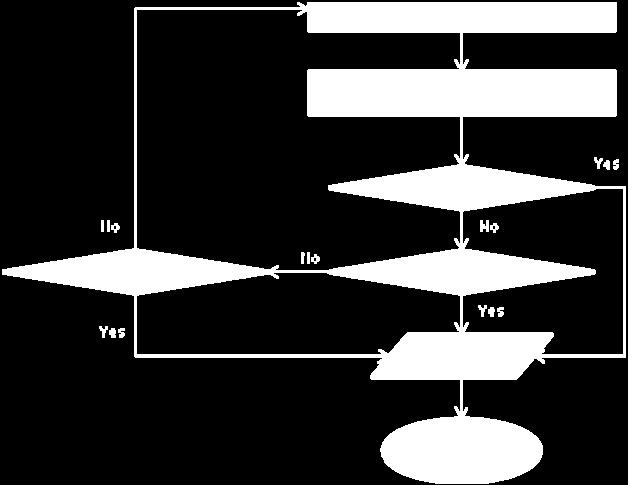
64 Figure 3-4. Overall DSAS algorithm. 64
Bond strength model for interfaces between nearsurface mounted (NSM) CFRP strips and concrete
 CFRP strips and concrete") University o Wollongong Research Online Faculty o Engineering and Inormation Sciences - Papers: Part A Faculty o Engineering and Inormation Sciences 2014 Bond strength model or interaces between nearsurace
University o Wollongong Research Online Faculty o Engineering and Inormation Sciences - Papers: Part A Faculty o Engineering and Inormation Sciences 2014 Bond strength model or interaces between nearsurace
AXIALLY LOADED FRP CONFINED REINFORCED CONCRETE CROSS-SECTIONS
 AXIALLY LOADED FRP CONFINED REINFORCED CONCRETE CROSS-SECTIONS Bernát Csuka Budapest University o Technology and Economics Department o Mechanics Materials and Structures Supervisor: László P. Kollár 1.
FATIGUE DURABILITY OF CONCRETE EXTERNALLY STRENGTHENED WITH FRP SHEETS
 FATIGUE DURABILITY OF CONCRETE EXTERNALLY STRENGTHENED WITH FRP SHEETS H. Diab () and Zhishen Wu () () Department o Urban and Civil Engineering, Ibaraki University, Japan Abstract A primary concern o the
Flexure: Behavior and Nominal Strength of Beam Sections
 4 5000 4000 (increased d ) (increased f (increased A s or f y ) c or b) Flexure: Behavior and Nominal Strength of Beam Sections Moment (kip-in.) 3000 2000 1000 0 0 (basic) (A s 0.5A s ) 0.0005 0.001 0.0015
Reliability assessment on maximum crack width of GFRPreinforced
 Fourth International Conerence on FRP Composites in Civil Engineering (CICE2008) 22-24July 2008, Zurich, Switzerland Reliability assessment on maximum crack width o GFRPreinorced concrete beams Z. He and
Design Guidelines A Scandinavian Approach
 Design Guidelines A Scandinavian Approach Pro. Björn Täljsten Luleå University o Technology SWEDEN Presented by Tech. Lic Anders Carolin 1 Pro. B. Täljsten Departmento Civiland Mining Engineering Division
Professor, Institute of Engineering Mechanics, Harbin. China 2. Ph.D Student, Institute of Engineering Mechanics, Harbin. China 3
 The 14 th World Conerence on Earthquake Engineering COMPARISON OF FRP-RETROFITTING STRATEGIES IN CHINESE AND ITALIAN CODES J. W. DAI 1, Y.R. WANG 2, B. JIN 1, 3, D.F.ZU 4, Silvia Alessandri 5, Giorgio
3.5 Analysis of Members under Flexure (Part IV)
") 3.5 Analysis o Members under Flexure (Part IV) This section covers the ollowing topics. Analysis o a Flanged Section 3.5.1 Analysis o a Flanged Section Introduction A beam can have langes or lexural eiciency.
3.5 Analysis o Members under Flexure (Part IV) This section covers the ollowing topics. Analysis o a Flanged Section 3.5.1 Analysis o a Flanged Section Introduction A beam can have langes or lexural eiciency.
S. Srinivasan, Technip Offshore, Inc., Houston, TX
 9 th ASCE Specialty Conerence on Probabilistic Mechanics and Structural Reliability PROBABILISTIC FAILURE PREDICTION OF FILAMENT-WOUND GLASS-FIBER Abstract REINFORCED COMPOSITE TUBES UNDER BIAXIAL LOADING
Behavior of RC Columns Confined with CFRP Sheets and Subjected to Eccentric Loading
 Lie Science Journal 2018;15(6) http:www.liesciencesite.com Behavior o RC Columns Conined with CFRP Sheets and Subjected to Eentric Loading Omar A. Farghal 1 and Mamdouh A. Kenawi 2 1 Civil Engineering
Finite element modeling incorporating nonlinearity of material behavior based on the fib Model Code 2010
 Peer-reviewed & Open access journal www.academicpublishingplatorms.com Finite element modeling incorporating non-linearity o material behavior ATI - Applied Technologies & Innovations Volume 5 Issue November
Calibration of Bond Coefficient for Deflection Control of FRP RC Members
 Fourth International Conerence on FRP Composites in Civil Engineering (CICE008) -4July 008, Zurich, Switzerland Calibration o Bond Coeicient or Delection Control o FRP RC Members R. Fico, A. Prota & G.
twenty one concrete construction: materials & beams ELEMENTS OF ARCHITECTURAL STRUCTURES: FORM, BEHAVIOR, AND DESIGN DR. ANNE NICHOLS SPRING 2014
 ELEMENTS OF ARCHITECTURAL STRUCTURES: FORM, BEHAVIOR, AND DESIGN DR. ANNE NICHOLS SPRING 2014 lecture twenty one concrete construction: http:// nisee.berkeley.edu/godden materials & beams Concrete Beams
Reliability of Axially Loaded Fiber-Reinforced-Polymer Confined Reinforced Concrete Circular Columns
 American J. o Engineering and Applied Sciences (1): 31-38, 009 ISSN 1941-700 009 Science Publications Reliability o Axially Loaded Fiber-Reinorced-Polymer Conined Reinorced Concrete Circular Columns Venkatarman
four mechanics of materials Mechanics of Materials Mechanics of Materials Knowledge Required MECHANICS MATERIALS
 EEMENTS OF RCHITECTUR STRUCTURES: FORM, BEHVIOR, ND DESIGN DR. NNE NICHOS SRING 2016 Mechanics o Materials MECHNICS MTERIS lecture our mechanics o materials www.carttalk.com Mechanics o Materials 1 S2009abn
Design criteria for Fiber Reinforced Rubber Bearings
 Design criteria or Fiber Reinorced Rubber Bearings J. M. Kelly Earthquake Engineering Research Center University o Caliornia, Berkeley A. Calabrese & G. Serino Department o Structural Engineering University
MICROMECHANICAL FAILURE ANALYSIS OF UNIDIRECTIONAL FIBER-REINFORCED COMPOSITES UNDER IN-PLANE AND TRANSVERSE SHEAR
 THE 19 TH INTERNATIONAL CONFERENCE ON COMPOSITE MATERIALS MICROMECHANICAL FAILURE ANALYSIS OF UNIDIRECTIONAL FIBER-REINFORCED COMPOSITES UNDER IN-PLANE AND TRANSVERSE SHEAR Lei Yang*, Ying Yan, Zhiguo
Seismic Pushover Analysis Using AASHTO Guide Specifications for LRFD Seismic Bridge Design
 Seismic Pushover Analysis Using AASHTO Guide Specifications for LRFD Seismic Bridge Design Elmer E. Marx, Alaska Department of Transportation and Public Facilities Michael Keever, California Department
AXIALLY LOADED FRP CONFINED REINFORCED CONCRETE CROSS-SECTIONS
 AXIALLY LOADED FRP CONFINED REINFORCED CONCRETE CROSS-SECTIONS PhD Thesis by Bernát Csuka Budapest University o Technology and Economics Department o Mechanics Materials and Structures Supervisor: László
five mechanics of materials Mechanics of Materials Mechanics of Materials Knowledge Required MECHANICS MATERIALS
 RCHITECTUR STRUCTURES: FORM, BEHVIOR, ND DESIGN DR. NNE NICHOS SUMMER 2014 Mechanics o Materials MECHNICS MTERIS lecture ive mechanics o materials www.carttalk.com Mechanics o Materials 1 rchitectural
Failure Diagrams of FRP Strengthened RC Beams
 Failure Diagrams o FRP Strengthened RC Beams Abstract Bo GAO a, Christopher K. Y. LEUNG b and Jang-Kyo KIM a* a Department o Mechanical Engineering and b Department o Civil Engineering Hong Kong University
Seismic Design, Assessment & Retrofitting of Concrete Buildings. fctm. h w, 24d bw, 175mm 8d bl, 4. w 4 (4) 2 cl
 2 cl") Seismic Design, Assessment & Retroitting o Concrete Buildings Table 5.1: EC8 rules or detailing and dimensioning o primary beams (secondary beams: as in DCL) DC H DCM DCL critical region length 1.5h w
Seismic Design, Assessment & Retroitting o Concrete Buildings Table 5.1: EC8 rules or detailing and dimensioning o primary beams (secondary beams: as in DCL) DC H DCM DCL critical region length 1.5h w
POST-PEAK BEHAVIOR OF FRP-JACKETED REINFORCED CONCRETE COLUMNS
 POST-PEAK BEHAVIOR OF FRP-JACKETED REINFORCED CONCRETE COLUMNS - Technical Paper - Tidarut JIRAWATTANASOMKUL *1, Dawei ZHANG *2 and Tamon UEDA *3 ABSTRACT The objective of this study is to propose a new
Fatigue verification of high loaded bolts of a rocket combustion chamber.
 Fatigue veriication o high loaded bolts o a rocket combustion chamber. Marcus Lehmann 1 & Dieter Hummel 1 1 Airbus Deence and Space, Munich Zusammenassung Rocket engines withstand intense thermal and structural
Title. Author(s)Dai, Jianguo; Ueda, Tamon; Sato, Yasuhiko. CitationJournal of Composites for Construction, 9(1): Issue Date Doc URL.
Dai, Jianguo; Ueda, Tamon; Sato, Yasuhiko. CitationJournal of Composites for Construction, 9(1): Issue Date Doc URL.") Title Development o the Nonlinear Bond Stress-Slip Model Simple Method Author(s)Dai, Jianguo; Ueda, Tamon; Sato, Yasuhiko CitationJournal o Composites or Construction, 9(1): 52-62 Issue Date 2005 Doc URL
Title Development o the Nonlinear Bond Stress-Slip Model Simple Method Author(s)Dai, Jianguo; Ueda, Tamon; Sato, Yasuhiko CitationJournal o Composites or Construction, 9(1): 52-62 Issue Date 2005 Doc URL
Chapter 8. Shear and Diagonal Tension
 Chapter 8. and Diagonal Tension 8.1. READING ASSIGNMENT Text Chapter 4; Sections 4.1-4.5 Code Chapter 11; Sections 11.1.1, 11.3, 11.5.1, 11.5.3, 11.5.4, 11.5.5.1, and 11.5.6 8.2. INTRODUCTION OF SHEAR
8.3 Design of Base Plate for Thickness
 8.3 Design o Base Plate or Thickness 8.3.1 Design o base plate or thickness (Elastic Design) Upto this point, the chie concern has been about the concrete oundation, and methods o design have been proposed
10/14/2011. Types of Shear Failure. CASE 1: a v /d 6. a v. CASE 2: 2 a v /d 6. CASE 3: a v /d 2
 V V Types o Shear Failure a v CASE 1: a v /d 6 d V a v CASE 2: 2 a v /d 6 d V a v CASE 3: a v /d 2 d V 1 Shear Resistance Concrete compression d V cz = Shear orce in the compression zone (20 40%) V a =
Lecture-04 Design of RC Members for Shear and Torsion
 Lecture-04 Design of RC Members for Shear and Torsion By: Prof. Dr. Qaisar Ali Civil Engineering Department UET Peshawar drqaisarali@uetpeshawar.edu.pk www.drqaisarali.com 1 Topics Addressed Design of
WELDED ALUMINUM ALLOY PLATE GIRDERS SUBJECTED TO SHEAR FORCE
 Advanced Steel Construction Vol. 8, No. 1, pp. 71-94 (2012) 71 WELDED ALUMINUM ALLOY PLATE GIRDERS SUBJECTED TO SHEAR FORCE Feng Zhou 1a, 1b, Ben Young 2,* and Hin-Chung Lam 3 1a Department o Building
Manufacturing Remaining Stresses in Truck Frame Rail's Fatigue Life Prediction
 Manuacturing Remaining Stresses in Truck Frame Rail's Fatigue Lie Prediction Claudiomar C. Cunha & Carlos A. N. Dias MSX International & Department o Naval Engineering EPUSP/USP/Brazil Department o Mechanical
Explanatory Examples for Ductile Detailing of RC Buildings
 Document No. :: IITK-GSD-EQ-V3.0 Final Report :: - Earthquake Codes IITK-GSD Project on Building Codes Explanatory Examples or Ductile Detailing o RC Buildings by Dr. R. K. Ingle Department o pplied echanics
Available online at ScienceDirect. Transportation Research Procedia 14 (2016 )
") Available online at www.sciencedirect.com ScienceDirect Transportation Research Procedia 14 (016 ) 411 40 6th Transport Research Arena April 18-1, 016 Resistance o reinorced concrete columns subjected
Available online at www.sciencedirect.com ScienceDirect Transportation Research Procedia 14 (016 ) 411 40 6th Transport Research Arena April 18-1, 016 Resistance o reinorced concrete columns subjected
PLATE GIRDERS II. Load. Web plate Welds A Longitudinal elevation. Fig. 1 A typical Plate Girder
 16 PLATE GIRDERS II 1.0 INTRODUCTION This chapter describes the current practice for the design of plate girders adopting meaningful simplifications of the equations derived in the chapter on Plate Girders
Guidelines for Nonlinear Finite Element Analysis of Concrete Structures
 P rd /P exp [%] Rijkswaterstaat Technical Document (RTD) Guidelines or Nonlinear Finite Element Analysis o Concrete Structures Doc.nr.: RTD 1016-1:2017 Version: 2.1 Status: Final Date: 15 June 2017 100
Chapter 6 Reliability-based design and code developments
 Chapter 6 Reliability-based design and code developments 6. General Reliability technology has become a powerul tool or the design engineer and is widely employed in practice. Structural reliability analysis
Modeling of Interfacial Debonding Induced by IC Crack for Concrete Beam-bonded with CFRP
 Proceedings of the World Congress on Engineering 21 Vol II WCE 21, June 2 - July 1, 21, London, U.K. Modeling of Interfacial Debonding Induced by IC Crack for Concrete Beam-bonded with CFRP Lihua Huang,
Plastic mechanism analysis of CHS stub columns strengthened using CFRP
 Plastic mechanism analis o CHS stub columns strengthened using CFRP M. Elchalakani School o rchitectural, Civil and Mechanical Engineering, Victoria University, Melbourne, ustralia M.R. Bambach Department
A STUDY OF 0 -FIBRE MICROBUCKLING IN MULTIDIRECTIONAL COMPOSITE LAMINATES
 A STUDY OF -FIBRE MICROBUCKLING IN MULTIDIRECTIONAL COMPOSITE LAMINATES P. Berbinau and C. Soutis Department o Aeronautics, Imperial College o Science, Technology & Medicine Prince Consort Rd, London SW7
Finite element modeling incorporating nonlinearity of material behavior based on the fib Model Code 2010
 Peer-reviewed & Open access journal www.academicpublishingplatorms.com The primary version o the journal is the on-line version Finite element modeling incorporating non-linearity o material behavior based
The achievable limits of operational modal analysis. * Siu-Kui Au 1)
") The achievable limits o operational modal analysis * Siu-Kui Au 1) 1) Center or Engineering Dynamics and Institute or Risk and Uncertainty, University o Liverpool, Liverpool L69 3GH, United Kingdom 1)
The achievable limits o operational modal analysis * Siu-Kui Au 1) 1) Center or Engineering Dynamics and Institute or Risk and Uncertainty, University o Liverpool, Liverpool L69 3GH, United Kingdom 1)
Numerical Simulation of the Behavior of Cracked Reinforced Concrete Members
 Materials Sciences and Applications, 2014, 5, 883-894 Published Online October 2014 in SciRes. http://www.scirp.org/journal/msa http://dx.doi.org/10.4236/msa.2014.512090 Numerical Simulation o the Behavior
Editorial Manager(tm) for The Arabian Journal for Science and Engineering B:
 for The Arabian Journal for Science and Engineering B:") Engineering Editorial Manager(tm) or The Arabian Journal or Science and Engineering B: Manuscript Drat Manuscript Number: AJSE-ENG-D-0-00R Title: Shear strengthening o short span reinorced concrete beams
Engineering Editorial Manager(tm) or The Arabian Journal or Science and Engineering B: Manuscript Drat Manuscript Number: AJSE-ENG-D-0-00R Title: Shear strengthening o short span reinorced concrete beams
EFFECT OF SHORT-DURATION-HIGH-IMPULSE VARIABLE AXIAL AND TRANSVERSE LOADS ON REINFORCED CONCRETE COLUMN
 EFFECT OF SHORT-DURATION-HIGH-IMPULSE VARIABLE AXIAL AND TRANSVERSE LOADS ON REINFORCED CONCRETE COLUMN By THIEN PHUOC TRAN A THESIS PRESENTED TO THE GRADUATE SCHOOL OF THE UNIVERSITY OF FLORIDA IN PARTIAL
Reliability-Based Load and Resistance Factor Design (LRFD) Guidelines for Stiffened Panels and Grillages of Ship Structures
 Guidelines for Stiffened Panels and Grillages of Ship Structures") Reliability-Based Load and Resistance actor Design (LRD) Guidelines or Stiened Panels and Grillages o Ship Structures Ibrahim A. Assakka 1, Bilal M. Ayyub 2, Paul E. Hess, III, 3 and Khaled Atua 4 ABSTRACT
Reliability-Based Load and Resistance actor Design (LRD) Guidelines or Stiened Panels and Grillages o Ship Structures Ibrahim A. Assakka 1, Bilal M. Ayyub 2, Paul E. Hess, III, 3 and Khaled Atua 4 ABSTRACT
HYDROELASTIC TAILORING AND OPTIMIZATION OF A COMPOSITE MARINE PROPELLER
 HYDROELASTIC TAILORING AND OPTIMIZATION OF A COMPOSITE MARINE PROPELLER José P. Blasques, Christian Berggreen and Poul Andersen Department o Mechanical Engineering, Technical University o Denmark Nils
Beam Bending Stresses and Shear Stress
 Beam Bending Stresses and Shear Stress Notation: A = name or area Aweb = area o the web o a wide lange section b = width o a rectangle = total width o material at a horizontal section c = largest distance
Design of Reinforced Concrete Beam for Shear
 Lecture 06 Design of Reinforced Concrete Beam for Shear By: Prof Dr. Qaisar Ali Civil Engineering Department UET Peshawar drqaisarali@uetpeshawar.edu.pk 1 Topics Addressed Shear Stresses in Rectangular
Evaluation of Scantlings of Corrugated Transverse Watertight Bulkheads in Non-CSR Bulk Carriers Considering Hold Flooding
 (1997) (Rev.1 1997) (Rev.1.1 Mar 1998 /Corr.1) (Rev. Sept 000) (Rev.3 eb 001) (Rev.4 Nov 001) (Rev.5 July 003) (Rev.6 July 004) (Rev.7 eb 006) (Corr.1 Oct 009) (Rev.8 May 010) (Rev.9 Apr 014) Evaluation
ON AN ESTIMATION OF THE DAMPING PROPERTIES OF WOVEN FABRIC COMPOSITES
 ON AN ESTIMATION OF THE DAMPING PROPERTIES OF WOVEN FABRIC COMPOSITES Masaru Zao 1, Tetsusei Kurashii 1, Yasumasa Naanishi 2 and Kin ya Matsumoto 2 1 Department o Management o Industry and Technology,
ε t increases from the compressioncontrolled Figure 9.15: Adjusted interaction diagram
 CHAPTER NINE COLUMNS 4 b. The modified axial strength in compression is reduced to account for accidental eccentricity. The magnitude of axial force evaluated in step (a) is multiplied by 0.80 in case
Finite Element Analysis of FRP Debonding Failure at the Tip of Flexural/Shear Crack in Concrete Beam
 Marquette University e-publications@marquette Civil and Environmental Engineering Faculty Research and Publications Civil and Environmental Engineering, Department of 12-1-2013 Finite Element Analysis
SOME RESEARCH ON FINITE ELEMENT ANALYSIS OF COMPOSITE MATERIALS
 The 3 rd International Conerence on DIAGNOSIS AND PREDICTION IN MECHANICAL ENGINEERING SYSTEMS DIPRE 12 SOME RESEARCH ON FINITE ELEMENT ANALYSIS OF Valeriu DULGHERU, Viorel BOSTAN, Marin GUŢU Technical
Life Prediction Under Multiaxial Fatigue
 Lie Prediction Under Multiaxial Fatigue D. Ramesh and M.M. Mayuram Department o Mechanical Engineering Indian Institute o Technology, Madras Chennai-600 036 (India) e-mail: mayuram@iitm.ac.in ABSTRACT
CHAPTER 6: ULTIMATE LIMIT STATE
 CHAPTER 6: ULTIMATE LIMIT STATE 6.1 GENERAL It shall be in accordance with JSCE Standard Specification (Design), 6.1. The collapse mechanism in statically indeterminate structures shall not be considered.
Bayesian Technique for Reducing Uncertainty in Fatigue Failure Model
 9IDM- Bayesian Technique or Reducing Uncertainty in Fatigue Failure Model Sriram Pattabhiraman and Nam H. Kim University o Florida, Gainesville, FL, 36 Copyright 8 SAE International ABSTRACT In this paper,
ULTIMATE SHEAR OF BEAMS STRENGTHENED WITH CFRP SHEETS
 ULTIMATE SHEAR OF BEAMS STRENGTHENED WITH CFRP SHEETS U. Ianniruberto and M. Imbimbo Department of Civil Engineering, University of Rome Tor Vergata Via di Tor Vergata 0, 0033, Rome, Italy SUMMARY: The
Size Effect on Strength of Bimaterial Joints: Computational Approach versus Analysis and Experiment
 Proc. (CD), 12th Intern. Con. on Fracture (ICF-12) (held in Ottawa, Canada, July 2009), Robert Bell, ed., Carleton University, pp. 1 10. Size Eect on Strength o Bimaterial Joints: Computational Approach
OUTLINE DESIGN OF COLUMN BASE PLATES AND STEEL ANCHORAGE TO CONCRETE 12/21/ Introduction 2. Base plates. 3. Anchor Rods
 DESIGN OF COLUMN BSE PLTES ND STEEL NCHORGE TO CONCRETE OUTLINE 1. Introduction 2. Base plates a. Material b. Design using ISC Steel Design Guide Concentric axial load xial load plus moment xial load plus
Keywords: creep, damage, finite element analysis, FSRF, low-cycle fatigue, type 316 steel, weldment
 --- 1 --- Application o the linear matching method to eep-atigue ailure analysis o uciorm weldment manuactured o the austenitic steel AISI type 316N(L) Yevgen Gorash and Haoeng Chen Department o Mechanical
Finite Element Modeling of Residual Thermal Stresses in Fiber-Reinforced Composites Using Different Representative Volume Elements
 Proceedings o the World Congress on Engineering 21 Vol II WCE 21, June 3 - July 2, 21, London, U.K. Finite Element Modeling o Residual Thermal Stresses in Fiber-Reinorced Composites Using Dierent Representative
Nonlinear static analysis PUSHOVER
 Nonlinear static analysis PUSHOVER Adrian DOGARIU European Erasmus Mundus Master Course Sustainable Constructions under Natural Hazards and Catastrophic Events 520121-1-2011-1-CZ-ERA MUNDUS-EMMC Structural
two structural analysis (statics & mechanics) Structural Requirements Structure Requirements Structure Requirements serviceability efficiency
 Structural Requirements Structure Requirements Structure Requirements serviceability efficiency") LIED RCHITECTURL STRUCTURES: STRUCTURL NLYSIS ND SYSTEMS DR. NNE NICHOLS SRING 018 lecture two structural analysis (statics & mechanics) nalysis 1 pplied rchitectural Structures 009abn Structural Requirements
LIED RCHITECTURL STRUCTURES: STRUCTURL NLYSIS ND SYSTEMS DR. NNE NICHOLS SRING 018 lecture two structural analysis (statics & mechanics) nalysis 1 pplied rchitectural Structures 009abn Structural Requirements
Material properties and vibration isolation Technical information
 Material properties and vibration isolation Technical inormation General inormation on Sylomer Sylomer is a special PUR elastomer manuactured by Getzner, which eatures a cellular, compact orm and is used
Gecko and many insects (Fig. 1) have evolved fibrillar structures
 have evolved fibrillar structures") Shape insensitive optimal adhesion o nanoscale ibrillar structures Huajian Gao* and Haimin Yao Max Planck Institute or Metals Research, Heisenbergstrasse 3, D-70569 Stuttgart, Germany Edited by Jan D.
Shape insensitive optimal adhesion o nanoscale ibrillar structures Huajian Gao* and Haimin Yao Max Planck Institute or Metals Research, Heisenbergstrasse 3, D-70569 Stuttgart, Germany Edited by Jan D.
Chapter. Materials. 1.1 Notations Used in This Chapter
 Chapter 1 Materials 1.1 Notations Used in This Chapter A Area of concrete cross-section C s Constant depending on the type of curing C t Creep coefficient (C t = ε sp /ε i ) C u Ultimate creep coefficient
Calculation Example. Strengthening for flexure
 01-08-1 Strengthening or lexure 1 Lat 1 L Sektion 1-1 (Skala :1) be h hw A bw FRP The beam i a part o a lab in a parking garage and need to be trengthened or additional load. Simply upported with L=8.0
Mechanics of Materials Primer
 Mechanics of Materials rimer Notation: A = area (net = with holes, bearing = in contact, etc...) b = total width of material at a horizontal section d = diameter of a hole D = symbol for diameter E = modulus
SHEAR CAPACITY OF REINFORCED CONCRETE COLUMNS RETROFITTED WITH VERY FLEXIBLE FIBER REINFORCED POLYMER WITH VERY LOW YOUNG S MODULUS
 SHEAR CAPACITY OF REINFORCED CONCRETE COLUMNS RETROFITTED WITH VERY FLEXILE FIER REINFORCED POLYMER WITH VERY LOW YOUNG S MODULUS Hu Shaoqing Supervisor: Susumu KONO ** MEE8165 ASTRACT FRP with low Young
MASSACHUSETTS INSTITUTE OF TECHNOLOGY DEPARTMENT OF MATERIALS SCIENCE AND ENGINEERING CAMBRIDGE, MASSACHUSETTS 02139
 MASSACHUSTTS INSTITUT OF TCHNOLOGY DPARTMNT OF MATRIALS SCINC AND NGINRING CAMBRIDG, MASSACHUSTTS 0239 322 MCHANICAL PROPRTIS OF MATRIALS PROBLM ST 4 SOLUTIONS Consider a 500 nm thick aluminum ilm on a
Design of Reinforced Concrete Beam for Shear
 Lecture 06 Design of Reinforced Concrete Beam for Shear By: Civil Engineering Department UET Peshawar drqaisarali@uetpeshawar.edu.pk Topics Addressed Shear Stresses in Rectangular Beams Diagonal Tension
Appendix G Analytical Studies of Columns
 Appendix G Analytical Studies of Columns G.1 Introduction Analytical parametric studies were performed to evaluate a number of issues related to the use of ASTM A103 steel as longitudinal and transverse
Optimization of Flexural capacity of Reinforced fibrous Concrete Beams Using Genetic Algorithm
 Optimization o Flexural capacity o Reinorced ibrous Concrete Beams Using Genetic Algorithm SUJI.D,NATESAN S.C, MURUGESAN.R Biography: Suji.D is a Research Scholar at Sathyabama Institute O Science and
AN EXPERIMENTAL AND NUMERICAL STUDY OF THE INFLUENCE OF LOCAL EFFECTS ON THE APPLICATION OF THE FIBRE PUSH-IN TESTS.
 AN EXPERIMENTAL AND NUMERICAL STUDY OF THE INFLUENCE OF LOCAL EFFECTS ON THE APPLICATION OF THE FIBRE PUSH-IN TESTS. Jon M. Molina-Aldareguía 1, M. Rodríguez 1, C. González 1, and J.LLorca 1, 1 Madrid
Numerical evaluation of plastic rotation capacity in RC beams
 Numerical evaluation o plastic rotation capacity in RC beams A.L. Gamino & T.N. Bittencourt Structural and Geotechnical Engineering epartment, Polytechnical School o São Paulo University, São Paulo, Brazil
Lab Exercise #5: Tension and Bending with Strain Gages
 Lab Exercise #5: Tension and Bending with Strain Gages Pre-lab assignment: Yes No Goals: 1. To evaluate tension and bending stress models and Hooke s Law. a. σ = Mc/I and σ = P/A 2. To determine material
A METHOD OF LOAD INCREMENTS FOR THE DETERMINATION OF SECOND-ORDER LIMIT LOAD AND COLLAPSE SAFETY OF REINFORCED CONCRETE FRAMED STRUCTURES
 A METHOD OF LOAD INCREMENTS FOR THE DETERMINATION OF SECOND-ORDER LIMIT LOAD AND COLLAPSE SAFETY OF REINFORCED CONCRETE FRAMED STRUCTURES Konuralp Girgin (Ph.D. Thesis, Institute of Science and Technology,
Design of Reinforced Concrete Structures (II)
") Design of Reinforced Concrete Structures (II) Discussion Eng. Mohammed R. Kuheil Review The thickness of one-way ribbed slabs After finding the value of total load (Dead and live loads), the elements are
Design of Reinforced Concrete Structures (II) Discussion Eng. Mohammed R. Kuheil Review The thickness of one-way ribbed slabs After finding the value of total load (Dead and live loads), the elements are
FRACTURE MECHANICS APPROACHES STRENGTHENING USING FRP MATERIALS
 Fracture Mechanics of Concrete Structures Proceedings FRAMCOS-3 AEDIFICATIO Publishers, D-79104 Freiburg, Germany FRACTURE MECHANICS APPROACHES STRENGTHENING USING FRP MATERIALS Triantafillou Department
MODELLING NON-LINEAR BEHAVIOUR OF STEEL FIBRE REINFORCED CONCRETE
 6th RILEM Symposium on Fibre-Reinforced Concretes (FRC) - BEFIB - September, Varenna, Italy MODELLING NON-LINEAR BEHAVIOUR OF STEEL FIBRE REINFORCED CONCRETE W. A. Elsaigh, J. M. Robberts and E.P. Kearsley
EFFECT OF SHEAR REINFORCEMENT ON FAILURE MODE OF RC BRIDGE PIERS SUBJECTED TO STRONG EARTHQUAKE MOTIONS
 EFFECT OF SHEAR REINFORCEMENT ON FAILURE MODE OF RC BRIDGE PIERS SUBJECTED TO STRONG EARTHQUAKE MOTIONS Atsuhiko MACHIDA And Khairy H ABDELKAREEM SUMMARY Nonlinear D FEM was utilized to carry out inelastic
Characterization of Internal State Variable for fiber fracture in UD Composite
 Characterization o Internal State ariable or iber racture in UD Composite Modris Megnis,, Povl Brondsted 3, Sai A. Rehman 4, Tanveer Ahmad 5 Summary The continuum damage mechanics is used to describe the
Module 2 Selection of Materials and Shapes. IIT, Bombay
 Module Selection o Materials and Shapes Lecture Selection o Materials - I Instructional objectives By the end o this lecture, the student will learn (a) what is a material index and how does it help in
MECHANICS OF MATERIALS. Prepared by Engr. John Paul Timola
 MECHANICS OF MATERIALS Prepared by Engr. John Paul Timola Mechanics of materials branch of mechanics that studies the internal effects of stress and strain in a solid body. stress is associated with the
A study on the Accelerated Life Test Coupled with Computation for Life Prediction of Product According to Wear and Damage
 International Journal o Mechanical & Mechatronics Engineering IJMME-IJENS Vol:15 No:03 106 A study on the Accelerated Lie Test Coupled with Computation or Lie Prediction o Product According to Wear and
Lecture-03 Design of Reinforced Concrete Members for Flexure and Axial Loads
 Lecture-03 Design of Reinforced Concrete Members for Flexure and Axial Loads By: Prof. Dr. Qaisar Ali Civil Engineering Department UET Peshawar drqaisarali@uetpeshawar.edu.pk www.drqaisarali.com Prof.
Evaluation of Flexural Stiffness for RC Beams During Fire Events
 3 rd International Structural Specialty Conference 3 ième conférence internationale spécialisée sur le génie des structures Edmonton, Alberta June 6-9, 202 / 6 au 9 juin 202 Evaluation of Flexural Stiffness
INPUT GROUND MOTION SELECTION FOR XIAOWAN HIGH ARCH DAM
 3 th World Conerence on Earthquake Engineering Vancouver, B.C., Canada August -6, 24 Paper No. 2633 INPUT GROUND MOTION LECTION FOR XIAOWAN HIGH ARCH DAM CHEN HOUQUN, LI MIN 2, ZHANG BAIYAN 3 SUMMARY In
9.5 Compression Members
 9.5 Compression Members This section covers the following topics. Introduction Analysis Development of Interaction Diagram Effect of Prestressing Force 9.5.1 Introduction Prestressing is meaningful when
RESOLUTION MSC.362(92) (Adopted on 14 June 2013) REVISED RECOMMENDATION ON A STANDARD METHOD FOR EVALUATING CROSS-FLOODING ARRANGEMENTS
 (Adopted on 14 June 2013) REVISED RECOMMENDATION ON A STANDARD METHOD FOR EVALUATING CROSS-FLOODING ARRANGEMENTS") (Adopted on 4 June 203) (Adopted on 4 June 203) ANNEX 8 (Adopted on 4 June 203) MSC 92/26/Add. Annex 8, page THE MARITIME SAFETY COMMITTEE, RECALLING Article 28(b) o the Convention on the International
(Adopted on 4 June 203) (Adopted on 4 June 203) ANNEX 8 (Adopted on 4 June 203) MSC 92/26/Add. Annex 8, page THE MARITIME SAFETY COMMITTEE, RECALLING Article 28(b) o the Convention on the International
The Application of Reliability Methods in the Design of Tophat Stiffened
 The Application o Reliability Methods in the Design o Tophat Stiened Composite Panels under In-plane Loading Yang N. (1)() & Das P. K., () (1) Harbin Engineering University, China ()University o Strathclyde,
Notched Strength Estimation of Graphite/Epoxy Laminated Composite with Central Crack under Uniaxial Tensile Loading
 International Journal o Composite Materials 5, 5(6): 77-8 DOI:.593/j.cmaterials.556.6 Notched Strength Estimation o Graphite/Epoxy Laminated Composite with Central Crack under Uniaxial Tensile Loading
Appendix J. Example of Proposed Changes
 Appendix J Example of Proposed Changes J.1 Introduction The proposed changes are illustrated with reference to a 200-ft, single span, Washington DOT WF bridge girder with debonded strands and no skew.
Parametric analysis and torsion design charts for axially restrained RC beams
 Structural Engineering and Mechanics, Vol. 55, No. 1 (2015) 1-27 DOI: http://dx.doi.org/10.12989/sem.2015.55.1.001 1 Parametric analysis and torsion design charts for axially restrained RC beams Luís F.A.
New model for Shear Failure of R/C Beam-Column Joints. Hitoshi Shiohara
 New model for Shear Failure of R/ Beam-olumn Joints Hitoshi Shiohara Dept. of Architectural Engineering, The University of Tokyo, Tokyo 3-8656, Japan; PH +8(3)584-659; FAX+8(3)584-656; email:shiohara@arch.t.u-tokyo.ac.jp
Analysis of Friction-Induced Vibration Leading to Eek Noise in a Dry Friction Clutch. Abstract
 The 22 International Congress and Exposition on Noise Control Engineering Dearborn, MI, USA. August 19-21, 22 Analysis o Friction-Induced Vibration Leading to Eek Noise in a Dry Friction Clutch P. Wickramarachi
A PROPOSAL OF DESIGN PROCEDURE FOR FLEXURAL STRENGTHENING RC BEAMS WITH FRP SHEET
 N. Kishi, E-89, 1/8 A PROPOSAL OF DESIGN PROCEDURE FOR FLEXURAL STRENGTHENING RC BEAMS WITH FRP SHEET Yusuke Kurihashi Norimitsu Kishi Hiroshi Mikami Sumiyuki Sawada Civil Engrg. Research Muroran Inst.
THREE DIMENSIONAL MECHANICAL MODEL TO SIMULATE THE NSM FRP STRIPS SHEAR STRENGTH CONTRIBUTION TO A RC BEAM: PARAMETRIC STUDIES
 THREE DIMENSIONA MECHANICA MODE TO SIMUATE THE NSM FRP STRIPS SHEAR STRENGTH CONTRIBUTION TO A RC BEAM: PARAMETRIC STUDIES Vincenzo Bianco 1, J.A.O. Barros 2 and Giorgio Monti 3 Abstract: This paper presents
COMPREHENSIVE RETROFIT EXAMPLE 1 MULTI-SPAN CIP REINFORCED CONCRETE BOX GIRDER BRIDGE
 COMPREHENSIVE RETROFIT EXAMPLE 1 MULTI-SPAN CIP REINFORCED CONCRETE BOX GIRDER BRIDGE 1. Problem Statement Evaluate a six-span cast-in-place reinorced concrete highway overcrossing located in southern
MODELING SLAB-COLUMN CONNECTIONS REINFORCED WITH GFRP UNDER LOCALIZED IMPACT
 MODELING SLAB-COLUMN CONNECTIONS REINFORCED WITH GFRP UNDER LOCALIZED IMPACT QI ZHANG and AMGAD HUSSEIN Faculty of Engineering, Memorial University of Newfoundland St. John s, Newfoundland, Canada, A1B