Microwave couplers. Outline
|
|
|
- Lynette O’Brien’
- 6 years ago
- Views:
Transcription
1 Microwave coupler Anja Skrivervik Laboratoire d'electromagnétime et d'acoutique Ecole Polytechnique fédérale de Lauanne CH-05 Lauanne Outline Theoretical approach Ideal coupler Real coupler Application : Hybrid ring Hybrid coupler
2 -port cattering matrix General adapted and reciprocal 3 flow chart a b b a 3 a 3 b 33 b 3 a 3
3 adapted and reciprocal and lole -port * * * 3 3 * * * = * * * * * * What doe it mean? + = 0 ( line3xcolumn ) x * * * = 0 ( linexcolumn ) x * * * ( ) * 3 3 = 0 6
4 ( ) * 3 3 = 0 t olution : 3 = 0, 0, 3 0 thu : + = 0 = 0 * * a b a 3 b b a b a 7 ( ) * 3 3 = 0 nd olution : = 3 election of reference plane : = 3 = jβ = ( linexcolumn) + + = ( line3xcolumn3) thu : = 3 = α with adequate ref. plane 8
5 nd olution ( ) ( ) + = 0 = α + ( linexcolumn ) * * * = 0 = β ( line3xcolumn) * * * α = 0, β = = = Ideal coupler * * * * * * = * * * * 3 3 * * = + = 0 + = + = 0 + = 3 + = 0
6 Ideal coupler = = α 3 = = β 3 α + β = 3 3 = αe = αe = β e = β e jϕ jη jψ jθ with ( ϕ+ η) = π+ ( ψ+ θ) + nπ and α> β by convention ymmetric coupler ψ = θ = π 0 α 0 jβ α 0 jβ 0 0 jβ 0 α jβ 0 α 0 a b a 3 b 3 α jβ α b a b a
7 aymmetric coupler ψ = 0, θ = π 0 α 0 β α 0 β 0 0 β 0 α β 0 α 0 a b a 3 b 3 -β β α β -β α b a b a 3 Summary : ideal coupler Coupling : LC = -0log0 β Attenuation : LA = -0log0 α α β input through 3 iolated coupled input through 3 iolated coupled

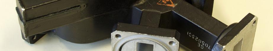
8 real coupler ο α β Attenuation : LA = -0log 0 α Coupling : LC = -0log 0 β Iolation : LI 3 = -0log 0 3 Iolation : LI = -0log 0 Directivity : LD 3 = LI 3 -LC = -0log 0 3 /β Directivity : LD = LI -LC = -0log 0 /β 5 example : 0 db waveguide coupler 6


9 example : magic T 7 example : magic T combined with 0dB coupler 8

![Example LC [db] β](/docs-images/71/66016062/images/10-1.jpg "α LA[dB] 0 0.")


10 Example : E Band 0 db coupler 9 Example LC [db] β α LA[dB]
11 Directivity : meaure of quality Microtrip hybrid coupler : 30 db Multihole waveguide coupler : 0 db Waveguide coupler ued in metrology : db Coupler ued in meaurement
12 with coupler amplitude meaurement with coupler Reflectometry preciion meaurement phae and amplitude meaurement 3 coupler reflectometry a 3 b3?
13 coupler reflectometry b3 3 3 b3c 3 3 a a - b 3 = ii 3 a b 3 b 3c = ii b 3c = 3 a 5 real coupler ii, 3, <<, but non equal to zero we need : coupling LC=-0logβ iolation LI3=-0log 3 LI=-0log The quality of the coupler i given by : directivity LD3=LI3-LC=-0log 3 /β LD=LI-LC=-0log /β 6
14 coupler reflectometry b3 b3c a a b 3 = a ii b3 ii3+ 3 = b + ( ) b 3c = a ( ) 3c coupler reflectometry 3 i non negligible at the numerator if ii << 3 i negligible at the denominator if the couple i of good quality : b3 3 = ii b 3c 3 The phae of the ignal are not known b b + b b ii 3c 3 3c 3 8
15 coupler reflectometry For a weak coupling (LC large) S The error term i directly the directivity of the coupler : b b + b b ii 3c 3 3c 3 LD [db] 3/ coupler reflectometry br b a A A A? b Aii + B = b C + D r 30 ii A= B= C = D= Ue adapter to put B=C=0 b ii3 = b r
16 coupler reflectometry ued for feed back amplitude meaurement br b a A A A? 3 coupler reflectometry ratiometer br b a A A A? 3
17 coupler reflectometry zero detector + A ϕ br b a A A A? 33 coupler reflectometry network analyer A ϕ br b a A A A? 3
18 Network analyer (principle) 35 Network analyer (principle) I f = 0 MHz L f = 300 khz U=Uo ρ co(ω if t+ϕ) U=Uo ρ co(ω Lf t+ϕ) ρ inϕ ρ coϕ Ur=Uoco(ω if t) Ur=Uoco(ω LF t) 36

19 Attenuation meaurement br b a? load Same principle than reflectometry 37 Microwave meaurement 38


20 Network Analyor 39 the quadrature hybrid the 80 hybrid example of utilization Example of coupler in printed technology 0
![The quadrature hybrid [ S] = 0](/docs-images/71/66016062/images/21-1.jpg "0 j 0 j 0 0 j 0 j 0 0 a b a 3 b")

21 The quadrature hybrid [ S] = 0 0 j 0 j 0 0 j 0 j 0 0 a b a 3 b b a b 3 a input through 3 j iolated coupled The quadrature hybrid
22 quadriport with double ymmetry () = = = = 33 = = = = 3 3 = = = = = = = = 3 3 quadriport with double ymmetry () o.c left-right : ymmetric excitation top-bottom : ymmetric excitation 3 o.c a = a = a = a 3 b = b = b = b 3 b ρ = = a
23 quadriport with double ymmetry (3) c.c left-right : antiymmetric excitation top-bottom : antiymmetric excitation 3 c.c a = a = a = a 3 b = b = b = b ρ 3 b aa aa = = aaa quadriport with double ymmetry () o.c left-right : ymmetric excitation top-bottom : antiymmetric excitation 3 c.c a = a = a = a 3 b = b = b = b 3 b ρa = a a a = + 3 6
24 quadriport with double ymmetry (5) c.c left-right : antiymmetric excitation top-bottom excitation 3 o.c a = a = a = a 3 b = b = b = b 3 b ρa = a a a = quadriport with double ymmetry (6) ρ ρ = ρa 3 ρ aa a ρ ρ a = 3 ρa ρaa 8
25 quadriport with double ymmetry (7) matching : =0 directivity : 3 =0 ρ + ρa + ρa + ρaa = 0 ρ+ ρa ρa ρaa = 0 ( ) arg ( ) ( ) arg ( ) ρ = ρ arg ρ ρ = π a a ρ = ρ arg ρ ρ = π aa a aa a 9 quadriport with double ymmetry (7) Lole cae : ( ρ ρ ) aa = = α ( ρ + ρ ) aa = = β ρ = ij by choice of reference plane Im ρ aa jβ ρ α Re ρ a ρa 50
 ejϕ ρ a = Y Y Y c c + jy cot( β d ) jy tan( β d ) Y c jy cot( β d )+ jy tan( β d ) ejϕ β d β d ρ a = Y Y c jy tan( β")
 Y c + jy tan( β d ) jy β d ) e jϕ c.c. ρ aa = Y c.o.")
26 application to printed hybrid 5 The quadrature hybrid ρ = Y c jy tan( β d ) jy tan( β d ) Y c + jy tan( β d )+ jy tan( β d ) ejϕ ρ a = Y Y Y c c + jy cot( β d ) jy tan( β d ) Y c jy cot( β d )+ jy tan( β d ) ejϕ β d β d ρ a = Y Y c jy tan( β d )+ jy cot( β d ) Y c + jy tan( β d ) jy β d ) e jϕ c.c. ρ aa = Y c.o. c + jy cot( β d )+ jy cot( β d ) Y c jy cot( β d ) jy cot( β d ) ejϕ with ρ = ρ a =α+jβ we get : ϕ = π Y Y = Y c ρ aa = ρ a = α+ jβ Y cot( β d )+ Y cot( β d )= 0 c.c. c.o. 5
27 The quadrature hybrid "eay" olution β d =β d = π Y = Y c α Y = Y c β α β take a negative value. Lenght : d = λ 8 d =λ 8 Hybrid coupler (3 db): α = β = Y = Y c Y = Y c 53 The quadrature hybrid "not o eay" olution Y = Y c cot β d Y ( ) = cot( β d ) [ ( )] [ ( )] α= Y c Y tan( β d )+ Y tan β d Y c + Y tan( β d )+ Y tan β d [ ( )] ( ) β= Y c Y tan( β d )+ Y tan β d Y c + Y tan( β d )+ Y tan β d [ ] ( ) Y c cot β d cot( β d ) 5


![0 8 8 6 6 Y [mm] 0 - Y [mm] 0 - - -](/docs-images/71/66016062/images/28-2.jpg "-6-6 -8-8 -0-0 - - - - - - -0-8 -6 - -")
![0 6 8 0 X [mm] - - -0-8 -6 - - 0 6 8 0](/docs-images/71/66016062/images/28-3.jpg "X [mm] -35-30 -5-0 -5-0 -5 [db] -35-30")
28 meaured verification 55 Near field meaurement at 3 GHz non corrigé Q-hybride - f=3 GHz - non corrigé corrigé Q-hybride - f=3 GHz - corrigé Y [mm] 0 - Y [mm] X [mm] X [mm] [db] [db] 56
![The 80 Hybrid [ S] = 0](/docs-images/71/66016062/images/29-1.jpg "0 0 0 0 0 0 0 a b a 3 b")


29 The 80 Hybrid [ S] = a b a 3 b 3 b a b a input Σ through 3 j iolated coupled 57 The printed 80 Hybrid rat race Hybrid ring 58
Lecture 17 Date:
 Lecture 17 Date: 09.03.017 The Quadrature Hybrid We began our discussion of dividers and couplers by considering important general properties of three- and four-port networks. This was followed by an analysis
Lecture 19 Date:
 Lecture 19 Date: 8.10.014 The Quadrature Hybrid We began our discussion of dividers and couplers by considering important general properties of three- and fourport networks. This was followed by an analysis
General Topology of a single stage microwave amplifier
 General Topology of a ingle tage microwave amplifier Tak of MATCH network (in and out): To preent at the active device uitable impedance Z and Z S Deign Step The deign of a mall ignal microwave amplifier
Microwave Network Analysis Lecture 1: The Scattering Parameters
 Microwave Network Analysis Lecture : The Scattering Parameters ELC 305a Fall 0 Department of Electronics and Communications Engineering Faculty of Engineering Cairo University Outline Review on Network
Measurement of B s Oscillations and CP Violation Results from DØ
 Meaurement of B Ocillation and CP Violation Reult from DØ John Ellion Univerity of California, Riveride for the DØ Collaboration PANIC 008, Eilat, Irael 1 The DØ Detector Tracker: Excellent coverage η
General Properties for Determining Power Loss and Efficiency of Passive Multi-Port Microwave Networks
 University of Massachusetts Amherst From the SelectedWorks of Ramakrishna Janaswamy 015 General Properties for Determining Power Loss and Efficiency of Passive Multi-Port Microwave Networks Ramakrishna
Solutions to Problems in Chapter 6
 Appendix F Solutions to Problems in Chapter 6 F.1 Problem 6.1 Short-circuited transmission lines Section 6.2.1 (book page 193) describes the method to determine the overall length of the transmission line
Some Interesting Properties of Scattering Matrix of Passive Microwave Devices
 Forum for Electromagnetic Research Methods and Application Technologies (FERMAT) Some Interesting Properties of Scattering Matrix of Passive Microwave Devices Ramakrishna Janaswamy Professor, Department
Four Ports. 1 ENGN4545/ENGN6545: Radiofrequency Engineering L#16
 Four Ports Theorems of four port networks 180 o and 90 o Hybrids Directional couplers Transmission line transformers, Four port striplines Rat-races, Wilkinsons, Magic-T s Circulators, Diplexers and Filter
Refinements to Incremental Transistor Model
 Refinements to Incremental Transistor Model This section presents modifications to the incremental models that account for non-ideal transistor behavior Incremental output port resistance Incremental changes
ECE 5260 Microwave Engineering University of Virginia. Some Background: Circuit and Field Quantities and their Relations
 ECE 5260 Microwave Engineering University of Virginia Lecture 2 Review of Fundamental Circuit Concepts and Introduction to Transmission Lines Although electromagnetic field theory and Maxwell s equations
Measurements of the Masses, Mixing, and Lifetimes, of B Hadrons at the Tevatron
 Meaurement of the Mae, Mixing, and Lifetime, of Hadron at the Tevatron Mike Strau The Univerity of Oklahoma for the CDF and DØ Collaboration 5 th Rencontre du Vietnam Hanoi, Vietnam Augut 5-11, 2004 Outline
ECE357H1F ELECTROMAGNETIC FIELDS FINAL EXAM. 28 April Examiner: Prof. Sean V. Hum. Duration: hours
 UNIVERSITY OF TORONTO FACULTY OF APPLIED SCIENCE AND ENGINEERING The Edward S. Rogers Sr. Department of Electrical and Computer Engineering ECE357H1F ELECTROMAGNETIC FIELDS FINAL EXAM 28 April 15 Examiner:
Introduction. A microwave circuit is an interconnection of components whose size is comparable with the wavelength at the operation frequency
 Introduction A microwave circuit is an interconnection of components whose size is comparable with the wavelength at the operation frequency Type of Components: Interconnection: it is not an ideal connection
Frequency-Domain Analysis of Transmission Line Circuits (Part 3)
") Frequency-Doain Analyi of Traniion ine ircuit (Part 3 Dr. Joé Erneto Raya ánchez Outline Differential traniion line oon ode ignaling Differential ode ignaling Mode converion Even and odd ode -coupled lole
Frequency-Doain Analyi of Traniion ine ircuit (Part 3 Dr. Joé Erneto Raya ánchez Outline Differential traniion line oon ode ignaling Differential ode ignaling Mode converion Even and odd ode -coupled lole
Design of Digital Filters
 Deign of Digital Filter Paley-Wiener Theorem [ ] ( ) If h n i a caual energy ignal, then ln H e dω< B where B i a finite upper bound. One implication of the Paley-Wiener theorem i that a tranfer function
Lecture 23 Date:
 Lecture 3 Date: 4.4.16 Plane Wave in Free Space and Good Conductor Power and Poynting Vector Wave Propagation in Loy Dielectric Wave propagating in z-direction and having only x-component i given by: E
Heavy Flavour results from Tevatron
 Heavy Flavour reult from Tevatron G.Boriov, Lancater Univerity, UK On behalf of CF and Ø collaboration Moriond-EW conference, la Thuile, 08 February 2012 Introduction For pat 10 year the Tevatron ha pioneered
Lecture 12. Microwave Networks and Scattering Parameters
 Lecture Microwave Networs and cattering Parameters Optional Reading: teer ection 6.3 to 6.6 Pozar ection 4.3 ElecEng4FJ4 LECTURE : MICROWAE NETWORK AND -PARAMETER Microwave Networs: oltages and Currents
ECE 107: Electromagnetism
 ECE 107: Electromagnetism Set 2: Transmission lines Instructor: Prof. Vitaliy Lomakin Department of Electrical and Computer Engineering University of California, San Diego, CA 92093 1 Outline Transmission
Beauty 2013, Bologna. Measurements of CP violation and mixing in Bs. 0 decays at LHCb. on behalf of the LHCb collaboration
 LPHE Beauty 13, Bologna Meaurement of CP violation and mixing in B decay at Frédéric Dupertui on behalf of the collaboration Laboratoire de Phyique de Haute Energie (LPHE) Ecole Polytechnique Fédérale
LAB MANUAL EXPERIMENT NO. 7
 LAB MANUAL EXPERIMENT NO. 7 Aim of the Experiment: Concept of Generalized N-port scattering parameters, and formulation of these parameters into 2-port reflection and transmission coefficients. Requirement:
Noise Figure Minimization of RC Polyphase Filters
 Noie Figure Mimization of olyphae Filter Jáno advánzky Abtract - ideband uppreion of polyphae filter i dependent of the ource and load impedance. Thi property i valid for any number of tage and any detung
ECE 604, Lecture 13. October 16, 2018
 ECE 604, Lecture 13 October 16, 2018 1 Introduction In this lecture, we will cover the following topics: Terminated Transmission Line Smith Chart Voltage Standing Wave Ratio (VSWR) Additional Reading:
Lab. 1. Entanglement and Bell inequalities
 Lab.. Entanglement and Bell inequalitie In quantum mechanic, two particle are called entangled if their tate cannot be factored into ingle-particle tate: Ψ Ψ Ψ Meaurement performed on the firt particle
ANTENNAS and MICROWAVES ENGINEERING (650427)
") Philadelphia University Faculty of Engineering Communication and Electronics Engineering ANTENNAS and MICROWAVES ENGINEERING (65427) Part 2 Dr. Omar R Daoud 1 General Considerations It is a two-port network
Philadelphia University Faculty of Engineering Communication and Electronics Engineering ANTENNAS and MICROWAVES ENGINEERING (65427) Part 2 Dr. Omar R Daoud 1 General Considerations It is a two-port network
A2 Assignment zeta Cover Sheet. C3 Differentiation all methods. C3 Sketch and find range. C3 Integration by inspection. C3 Rcos(x-a) max and min
 max and min") A Assignment zeta Cover Sheet Name: Question Done Backpack Ready? Topic Comment Drill Consolidation M1 Prac Ch all Aa Ab Ac Ad Ae Af Ag Ah Ba C3 Modulus function Bb C3 Modulus function Bc C3 Modulus function
A Assignment zeta Cover Sheet Name: Question Done Backpack Ready? Topic Comment Drill Consolidation M1 Prac Ch all Aa Ab Ac Ad Ae Af Ag Ah Ba C3 Modulus function Bb C3 Modulus function Bc C3 Modulus function
A New Method For Simultaneously Measuring And Analyzing PLL Transfer Function And Noise Processes
 A New Method For Simultaneouly Meauring And Analyzing PLL Tranfer Function And Noie Procee Mike Li CTO, Ph.D. Jan Wiltrup Corporate Conultant 1 Outline Introduction Phae Locked-Loop (PLL) and Noie Procee
FINAL EXAM IN FYS-3007
 Page 1 of 4 pages + chart FINAL EXAM IN FYS-007 Exam in : Fys-007 Microwave Techniques Date : Tuesday, May 1, 2011 Time : 09.00 1.00 Place : Åsgårdveien 9 Approved remedies : All non-living and non-communicating
Measurement of lower hybrid waves using microwave scattering technique in Alcator C-Mod
 Measurement of lower hybrid waves using microwave scattering technique in Alcator C-Mod S. Baek, R. Parker, S. Shiraiwa, A. Dominguez, E. Marmar, G. Wallace, G. J. Kramer* Plasma Science and Fusion Center,
Algebra II B Review 5
 Algebra II B Review 5 Multiple Choice Identify the choice that best completes the statement or answers the question. 1. Find the measure of the angle below. y x 40 ο a. 135º b. 50º c. 310º d. 270º Sketch
ECE Microwave Engineering
 ECE 537-635 Microwave Engineering Fall 8 Prof. David R. Jackson Dept. of ECE Adapted from notes by Prof. Jeffery T. Williams Notes Power Dividers and Circulators Power Dividers and Couplers A power divider
International Distinguished Lecturer Program
 U 005-006 International Distinguished Lecturer Program Ken-ya Hashimoto Chiba University Sponsored by The Institute of Electrical and Electronics Engineers (IEEE) Ultrasonics, Ferroelectrics and Frequency
Broadband Butler Matrices with the Use of High-Pass LC Sections as Left-Handed Transmission Lines
 36 K. SASZEK, S. GRUSZZYNSKI, K. WINZA, BROADBAND BULER MARIES Broadband Butler Matrice with the Ue of High-Pa L Section a Left-Handed ranmiion Line Kamil SASZEK, Slawomir GRUSZZYNSKI, Krzyztof WINZA AGH
Massachusetts Institute of Technology Department of Electrical Engineering and Computer Science Quantum Optical Communication
 Massachusetts Institute of Technology Department of Electrical Engineering and Computer Science 6.453 Quantum Optical Communication Date: Thursday, October 13, 016 Lecture Number 10 Fall 016 Jeffrey H.
The Co-Conical Field Generation System A 40 GHz Antenna Test Cell
 A 40 GHz Antenna Test Cell David R. Novotny and Robert T. Johnk RF Technology Division 325 Broadway Boulder, Colorado 80303-3328 http://www.boulder.nist.gov/div813/rffields/emc_emi/co_con.html An Effort
EELE 3332 Electromagnetic II Chapter 10
 EELE 333 Electromagnetic II Chapter 10 Electromagnetic Wave Propagation Ilamic Univerity of Gaza Electrical Engineering Department Dr. Talal Skaik 01 1 Electromagnetic wave propagation A changing magnetic
III. Spherical Waves and Radiation
 III. Spherical Waves and Radiation Antennas radiate spherical waves into free space Receiving antennas, reciprocity, path gain and path loss Noise as a limit to reception Ray model for antennas above a
Graduate Diploma in Engineering Circuits and waves
 9210-112 Graduate Diploma in Engineering Circuits and waves You should have the following for this examination one answer book non-programmable calculator pen, pencil, ruler No additional data is attached
Non-Sinusoidal Waves on (Mostly Lossless)Transmission Lines
Transmission Lines") Non-Sinusoidal Waves on (Mostly Lossless)Transmission Lines Don Estreich Salazar 21C Adjunct Professor Engineering Science October 212 https://www.iol.unh.edu/services/testing/sas/tools.php 1 Outline of
Non-Sinusoidal Waves on (Mostly Lossless)Transmission Lines Don Estreich Salazar 21C Adjunct Professor Engineering Science October 212 https://www.iol.unh.edu/services/testing/sas/tools.php 1 Outline of
How to measure complex impedance at high frequencies where phase measurement is unreliable.
 Objectives In this course you will learn the following Various applications of transmission lines. How to measure complex impedance at high frequencies where phase measurement is unreliable. How and why
Flight Dynamics & Control Equations of Motion of 6 dof Rigid Aircraft-Kinematics
 Flight Dynamic & Control Equation of Motion of 6 dof Rigid Aircraft-Kinematic Harry G. Kwatny Department of Mechanical Engineering & Mechanic Drexel Univerity Outline Rotation Matrix Angular Velocity Euler
Comparison of Hardware Tests with SIMULINK Models of UW Microgrid
 Comparion of Hardware Tet with SIMULINK Model of UW Microgrid Introduction Thi report include a detailed dicuion of the microource available on the Univerity- of- Wiconin microgrid. Thi include detail
II Transmitter and Receiver Design
 8/3/6 transmission lines 1/7 II Transmitter and Receiver Design We design radio systems using RF/microwave components. Q: Why don t we use the usual circuit components (e.g., resistors, capacitors, op-amps,
Lipparini* anazysis which compare favourabzy with experimentaz results. The same modez. described. It is shown that the discrepancies between computed
 ACCURATE ANALYSIS AND DESIGN OF MICROSTRIP INTERDIGITATED COUPLERS Vittorio Rizzoli*- Alessandro Lipparini* Abstract. The ezectricaz behaviour of interdigitated directionaz coupzers in an inhomogeneous
Statistics of Impedance and Scattering Matrices of Chaotic Microwave Cavities with Multiple Ports
 Statistics of Impedance and Scattering Matrices of Chaotic Microwave Cavities with Multiple Ports Xing Zheng, Thomas M. Antonsen Jr., and Edward Ott Department of Physics and Institute for Research in
Microwave Network Analysis
 Prof. Dr. Mohammad Tariqul Islam titareq@gmail.my tariqul@ukm.edu.my Microwave Network Analysis 1 Text Book D.M. Pozar, Microwave engineering, 3 rd edition, 2005 by John-Wiley & Sons. Fawwaz T. ILABY,
Microwave Phase Shift Using Ferrite Filled Waveguide Below Cutoff
 Microwave Phase Shift Using Ferrite Filled Waveguide Below Cutoff CHARLES R. BOYD, JR. Microwave Applications Group, Santa Maria, California, U. S. A. ABSTRACT Unlike conventional waveguides, lossless
A reciprocity relationship for random diffuse fields in acoustics and structures with application to the analysis of uncertain systems.
 A reciprocity relationship for random diffuse fields in acoustics and structures with application to the analysis of uncertain systems Robin Langley Example 1: Acoustic loads on satellites Arianne 5 Launch
Electron Spin Resonance Study Using Microwave Techniques
 Electron Spin Resonance Study Using Microwave Techniques University of California, Santa Cruz September 12, 2006 Contents 0.1 Introduction......................................... 1 0.2 Kramers-Krönig
Lecture 23: Basic Properties of Dividers and Couplers.
 Whites, EE 48/58 Lecture 23 age of 9 Lecture 23: Basic roperties of Dividers and Couplers. For the remainder of this course we re going to investigate a plethora of microwave devices and circuits both
Lecture 6: Resonance II. Announcements
 EES 5 Spring 4, Lecture 6 Lecture 6: Reonance II EES 5 Spring 4, Lecture 6 Announcement The lab tart thi week You mut how up for lab to tay enrolled in the coure. The firt lab i available on the web ite,
Road Map. Potential Applications of Antennas with Metamaterial Loading
 Road Map Potential Applications of Antennas with Metamaterial Loading Filiberto Bilotti Department of Applied Electronics University of Roma Tre Rome, Italy The history of metamaterials Metamaterial terminology
A Novel Tunable Dual-Band Bandstop Filter (DBBSF) Using BST Capacitors and Tuning Diode
 Using BST Capacitors and Tuning Diode") Progress In Electromagnetics Research C, Vol. 67, 59 69, 2016 A Novel Tunable Dual-Band Bandstop Filter (DBBSF) Using BST Capacitors and Tuning Diode Hassan Aldeeb and Thottam S. Kalkur * Abstract A novel
Progress In Electromagnetics Research C, Vol. 67, 59 69, 2016 A Novel Tunable Dual-Band Bandstop Filter (DBBSF) Using BST Capacitors and Tuning Diode Hassan Aldeeb and Thottam S. Kalkur * Abstract A novel
Lecture 12 Date:
 Lecture 12 Date: 09.02.2017 Microstrip Matching Networks Series- and Shunt-stub Matching Quarter Wave Impedance Transformer Microstrip Line Matching Networks In the lower RF region, its often a standard
Remote entanglement of transmon qubits
 Remote entanglement of transmon qubits 3 Michael Hatridge Department of Applied Physics, Yale University Katrina Sliwa Anirudh Narla Shyam Shankar Zaki Leghtas Mazyar Mirrahimi Evan Zalys-Geller Chen Wang
Retract. Press down D RG MG LG S. Recess. I-V Converter VNA. Gate ADC. DC Bias. 20 mk. Amplifier. Attenuators. 0.
 a Press down b Retract D RG S c d 2 µm Recess 2 µm.5 µm Supplementary Figure 1 CNT mechanical transfer (a) Schematics showing steps of pressing down and retracting during the transfer of the CNT from the
Standard Model. Overview
 Standard Model Quark mixing and CP violation Overview Quark weak and trong eigentate generation review K 0 mixing 3 generation review K 0 mixing, B 0 mixing CP violation Alternative parametriation of CKM
A2 Assignment lambda Cover Sheet. Ready. Done BP. Question. Aa C4 Integration 1 1. C4 Integration 3
 A Assignment lambda Cover Sheet Name: Question Done BP Ready Topic Comment Drill Mock Exam Aa C4 Integration sin x+ x+ c 4 Ab C4 Integration e x + c Ac C4 Integration ln x 5 + c Ba C Show root change of
The electric field produced by oscillating charges contained in a slab
 The electric field produced by oscillating charges contained in a slab Ref: Feynman Lectures Vol-1, Chapter 31 1. An accelerated charge produces electromagnetic fields 2. Calculation of the field produced
arxiv: v1 [hep-ph] 2 Jul 2016
![arxiv: v1 [hep-ph] 2 Jul 2016](/thumbs/73/69091835.jpg "arxiv: v1 [hep-ph] 2 Jul 2016") Tranvere Target Azimuthal Single Spin Aymmetry in Elatic e N Scattering Tareq Alhalholy and Matthia Burkardt Department of Phyic, New Mexico State Univerity, La Cruce, NM 883-1, U.S.A. arxiv:167.1287v1
Tranvere Target Azimuthal Single Spin Aymmetry in Elatic e N Scattering Tareq Alhalholy and Matthia Burkardt Department of Phyic, New Mexico State Univerity, La Cruce, NM 883-1, U.S.A. arxiv:167.1287v1
( ) 2. 1) Bode plots/transfer functions. a. Draw magnitude and phase bode plots for the transfer function
 2. 1) Bode plots/transfer functions. a. Draw magnitude and phase bode plots for the transfer function") ECSE CP7 olution Spring 5 ) Bode plot/tranfer function a. Draw magnitude and phae bode plot for the tranfer function H( ). ( ) ( E4) In your magnitude plot, indicate correction at the pole and zero. Step
ECSE CP7 olution Spring 5 ) Bode plot/tranfer function a. Draw magnitude and phae bode plot for the tranfer function H( ). ( ) ( E4) In your magnitude plot, indicate correction at the pole and zero. Step
Reference:W:\Lib\MathCAD\Default\defaults.mcd
 4/9/9 Page of 5 Reference:W:\Lib\MathCAD\Default\default.mcd. Objective a. Motivation. Finite circuit peed, e.g. amplifier - effect on ignal. E.g. how "fat" an amp do we need for audio? For video? For
EE C245 ME C218 Introduction to MEMS Design
 EE C45 ME C8 Introduction to MEMS Deign Fall 007 Prof. Clark T.-C. Nguyen Dept. of Electrical Engineering & Computer Science Univerity of California at Berkeley Berkeley, CA 9470 Lecture 5: Output t Sening
RF engineering basic concepts: S-parameters
 RF engineering basic concepts: -parameters F. Caspers CERN, Geneva, witzerland Abstract The concept of describing RF circuits in terms of waves is discussed and the -matrix and related matrices are defined.
Plane Waves GATE Problems (Part I)
") Plane Waves GATE Problems (Part I). A plane electromagnetic wave traveling along the + z direction, has its electric field given by E x = cos(ωt) and E y = cos(ω + 90 0 ) the wave is (a) linearly polarized
Plane Waves GATE Problems (Part I). A plane electromagnetic wave traveling along the + z direction, has its electric field given by E x = cos(ωt) and E y = cos(ω + 90 0 ) the wave is (a) linearly polarized
Transmission Lines in the Frequency Domain
 Berkeley Transmission Lines in the Frequency Domain Prof. Ali M. Niknejad U.C. Berkeley Copyright c 2016 by Ali M. Niknejad August 30, 2017 1 / 38 Why Sinusoidal Steady-State? 2 / 38 Time Harmonic Steady-State
Chapter 9: Controller design. Controller design. Controller design
 Chapter 9. Controller Deign 9.. Introduction 9.2. Eect o negative eedback on the network traner unction 9.2.. Feedback reduce the traner unction rom diturbance to the output 9.2.2. Feedback caue the traner
Publication V by authors
 Publication Kontantin S. Kotov and Jorma J. Kyyrä. 008. nertion lo and network parameter in the analyi of power filter. n: Proceeding of the 008 Nordic Workhop on Power and ndutrial Electronic (NORPE 008).
Quantum Field Theory 2011 Solutions
 Quantum Field Theory 011 Solution Yichen Shi Eater 014 Note that we ue the metric convention + ++). 1. State and prove Noether theorem in the context of a claical Lagrangian field theory defined in Minkowki
8.1.6 Quadratic pole response: resonance
 8.1.6 Quadratic pole response: resonance Example G(s)= v (s) v 1 (s) = 1 1+s L R + s LC L + Second-order denominator, of the form 1+a 1 s + a s v 1 (s) + C R Two-pole low-pass filter example v (s) with
NAME DATE PERIOD. Trigonometric Identities. Review Vocabulary Complete each identity. (Lesson 4-1) 1 csc θ = 1. 1 tan θ = cos θ sin θ = 1
 1 csc θ = 1. 1 tan θ = cos θ sin θ = 1") 5-1 Trigonometric Identities What You ll Learn Scan the text under the Now heading. List two things that you will learn in the lesson. 1. 2. Lesson 5-1 Active Vocabulary Review Vocabulary Complete each
5-1 Trigonometric Identities What You ll Learn Scan the text under the Now heading. List two things that you will learn in the lesson. 1. 2. Lesson 5-1 Active Vocabulary Review Vocabulary Complete each
C.-H. Liang, Y. Shi, and T. Su National Key Laboratory of Antennas and Microwave Technology Xidian University Xi an , China
 Progress In Electromagnetics Research, PIER 14, 253 266, 21 S PARAMETER THEORY OF LOSSLESS BLOCK NETWORK C.-H. Liang, Y. Shi, and T. Su National Key Laboratory of Antennas and Microwave Technology Xidian
ECE 6340 Intermediate EM Waves. Fall Prof. David R. Jackson Dept. of ECE. Notes 17
 ECE 634 Intermediate EM Waves Fall 16 Prof. David R. Jacson Dept. of ECE Notes 17 1 General Plane Waves General form of plane wave: E( xz,, ) = Eψ ( xz,, ) where ψ ( xz,, ) = e j( xx+ + zz) The wavenumber
Dr. Vahid Nayyeri. Microwave Circuits Design
 Lect. 8: Microwave Resonators Various applications: including filters, oscillators, frequency meters, and tuned amplifiers, etc. microwave resonators of all types can be modelled in terms of equivalent
Experiment 06 - Extraction of Transmission Line Parameters
 ECE 451 Automated Microwave Measurements Laboratory Experiment 06 - Extraction of Transmission Line Parameters 1 Introduction With the increase in both speed and complexity of mordern circuits, modeling
Topic 5: Transmission Lines
 Topic 5: Transmission Lines Profs. Javier Ramos & Eduardo Morgado Academic year.13-.14 Concepts in this Chapter Mathematical Propagation Model for a guided transmission line Primary Parameters Secondary
16.400/453J Human Factors Engineering. Manual Control II
 16.4/453J Human Factor Engineering Manual Control II Pilot Input 16.4/453 Pitch attitude Actual pitch error 8 e attitude 8 Deired pitch attitude 8 c Digital flight control computer Cockpit inceptor Fly-by-wire
sin cos 1 1 tan sec 1 cot csc Pre-Calculus Mathematics Trigonometric Identities and Equations
 Pre-Calculus Mathematics 12 6.1 Trigonometric Identities and Equations Goal: 1. Identify the Fundamental Trigonometric Identities 2. Simplify a Trigonometric Expression 3. Determine the restrictions on
Chapter 8: Converter Transfer Functions
 Chapter 8. Converter Transfer Functions 8.1. Review of Bode plots 8.1.1. Single pole response 8.1.2. Single zero response 8.1.3. Right half-plane zero 8.1.4. Frequency inversion 8.1.5. Combinations 8.1.6.
Chapter 9: Controller design
 Chapter 9. Controller Design 9.1. Introduction 9.2. Effect of negative feedback on the network transfer functions 9.2.1. Feedback reduces the transfer function from disturbances to the output 9.2.2. Feedback
Transmission Line Theory
 S. R. Zinka zinka@vit.ac.in School of Electronics Engineering Vellore Institute of Technology April 26, 2013 Outline 1 Free Space as a TX Line 2 TX Line Connected to a Load 3 Some Special Cases 4 Smith
Microwave Oscillators Design
 Microwave Oscillators Design Oscillators Classification Feedback Oscillators β Α Oscillation Condition: Gloop = A β(jω 0 ) = 1 Gloop(jω 0 ) = 1, Gloop(jω 0 )=2nπ Negative resistance oscillators Most used
Chapter - 7 Power Dividers and Couplers
 4//7 7_1 Basic Properties of Dividers and Couplers 1/ Chapter - 7 Power Dividers and Couplers One of the most fundamental problems in microwave engineering is how to efficiently divide signal power. 1.
Aperture Antennas 1 Introduction
 1 Introduction Very often, we have antennas in aperture forms, for example, the antennas shown below: Pyramidal horn antenna Conical horn antenna 1 Paraboloidal antenna Slot antenna Analysis Method for.1
Supplementary Figure 1 Simulated field patterns according to experimental results in
 Supplementary Figure 1 Simulated field patterns according to experimental results in Fig. 4. a, An insulating bulk state, corresponding to Fig. 4b. b, A topological edge state, corresponding to Fig. 4c.
Non-reciprocal passive protection of HF transmitters from reflection failure by the help of semiconductor isolators
 MEASUREMENT 009, Proceedings of the 7 th International Conference, Smolenice, Slovakia Non-reciprocal passive protection of HF transmitters from reflection failure by the help of semiconductor isolators
Left-Handed (LH) Structures and Retrodirective Meta-Surface
 Structures and Retrodirective Meta-Surface") Left-Handed (LH Structures and Retrodirective Meta-Surface Christophe Caloz, Lei Liu, Ryan Miyamoto and Tatsuo Itoh Electrical Engineering Department University of California, Los Angeles AGENDA I. LH
Left-Handed (LH Structures and Retrodirective Meta-Surface Christophe Caloz, Lei Liu, Ryan Miyamoto and Tatsuo Itoh Electrical Engineering Department University of California, Los Angeles AGENDA I. LH
Delhi Noida Bhopal Hyderabad Jaipur Lucknow Indore Pune Bhubaneswar Kolkata Patna Web: Ph:
 Serial : Ch1_EE_C_Power Electronic_6818 Delhi Noida Bhopal Hyderabad Jaipur ucknow Indore Pune Bhubanewar Kolkata Patna Web: E-mail: info@madeeay.in Ph: 11-451461 CASS ES 18-19 EECRICA ENGINEERING Subject
B Physics Theory Overview
 B Phyic Theory Overview Standard Model @ LHC Copenhagen April 13, 2012 Martin Gorahn TU München-IAS & Excellence Cluter `Univere 1 Flavour Phyic Flavour Phyic: Effect of highly virtual particle at lower
PHY3128 / PHYM203 (Electronics / Instrumentation) Transmission Lines
 Transmission Lines") Transmission Lines Introduction A transmission line guides energy from one place to another. Optical fibres, waveguides, telephone lines and power cables are all electromagnetic transmission lines. are
Transmission Lines Introduction A transmission line guides energy from one place to another. Optical fibres, waveguides, telephone lines and power cables are all electromagnetic transmission lines. are
DUAL-BAND COMPOSITE RIGHT/LEFT-HANDED RING ANTENNA WITH LINEAR/CIRCULAR POLARIZATION CAPABILITY
 DUAL-BAND COMPOSITE IGHT/LEFT-HANDED ING ANTENNA WITH LINEA/CICULA POLAIZATION CAPABILITY A. ennings (), S. Otto (), T. Liebig (), C. Caloz (), I. Wolff () () IMST GmbH, Carl-Friedrich-Gauß-Str., D-47475
Ripple Method for Evaluating Residual Errors
 Ripple Method for Evaluating Residual Errors H. Heuermann Univ. of Applied Sciences Aachen, Institute of High Frequency Tech., Eupener Str. 7, D-5266 Aachen, Germany Heuermann@FH-Aachen.de Heuermann HF-Technik
Functional quantum nodes for entanglement distribution
 61 Chapter 4 Functional quantum nodes for entanglement distribution This chapter is largely based on ref. 36. Reference 36 refers to the then current literature in 2007 at the time of publication. 4.1
Noise Correlations in Dual Frequency VECSEL
 Noise Correlations in Dual Frequency VECSEL S. De, A. El Amili, F. Bretenaker Laboratoire Aimé Cotton, CNRS, Orsay, France V. Pal, R. Ghosh Jawaharlal Nehru University, Delhi, India M. Alouini Institut
Contribution of Feed Waveguide on the Admittance Characteristics Of Coplanar Slot Coupled E-H Tee Junction
 ISSN(Online): 30-9801 Contribution of Feed Waveguide on the Admittance Characteristics Of Coplanar Slot Coupled E-H Tee Junction M.Murali, Prof. G.S.N Raju Research Scholar, Dept.of ECE, Andhra University,
LHCb Physics, Performance, Prospects
 7th Patra Workhop Mykono, June 26-July 1, 211 LHCb Phyic, Performance, Propect Olaf Steinkamp on behalf of the LHCb collaboration Phyik-Intitut der Univerität Zürich Winterthurertrae 19 CH-857 Zürich olaf@phyik.uzh.ch
ISSN: [Basnet* et al., 6(3): March, 2017] Impact Factor: 4.116
![ISSN: [Basnet* et al., 6(3): March, 2017] Impact Factor: 4.116](/thumbs/95/123902996.jpg "ISSN: [Basnet* et al., 6(3): March, 2017] Impact Factor: 4.116") IJESR INERNAIONAL JOURNAL OF ENGINEERING SCIENCES & RESEARCH ECHNOLOGY DIREC ORQUE CONROLLED INDUCION MOOR DRIVE FOR ORQUE RIPPLE REDUCION Bigyan Banet Department of Electrical Engineering, ribhuvan Univerity,
IJESR INERNAIONAL JOURNAL OF ENGINEERING SCIENCES & RESEARCH ECHNOLOGY DIREC ORQUE CONROLLED INDUCION MOOR DRIVE FOR ORQUE RIPPLE REDUCION Bigyan Banet Department of Electrical Engineering, ribhuvan Univerity,
22 Phasor form of Maxwell s equations and damped waves in conducting media
 22 Phasor form of Maxwell s equations and damped waves in conducting media When the fields and the sources in Maxwell s equations are all monochromatic functions of time expressed in terms of their phasors,
Mechanics Physics 151
 Mechanic Phyic 151 Lecture 7 Scattering Problem (Chapter 3) What We Did Lat Time Dicued Central Force Problem l Problem i reduced to one equation mr = + f () r 3 mr Analyzed qualitative behavior Unbounded,