STUDY OF DYNAMIC EFFECTS IN MICROPARTICLE ADHESION USING ATOMIC FORCE MICROSCOPY
|
|
|
- Randolph Cannon
- 5 years ago
- Views:
Transcription
1 STUDY OF DYNAMIC EFFECTS IN MICROPARTICLE ADHESION USING ATOMIC FORCE MICROSCOPY A Thesis by ANSHUL KAUSHIK Submitted to the Office of Graduate Studies of Texas A&M University in partial fulfillment of the requirements for the degree of MASTER OF SCIENCE December 2004 Major Subject: Mechanical Engineering
2 STUDY OF DYNAMIC EFFECTS IN MICROPARTICLE ADHESION USING ATOMIC FORCE MICROSCOPY A Thesis by ANSHUL KAUSHIK Submitted to Texas A&M University in partial fulfillment of the requirements for the degree of MASTER OF SCIENCE Approved as to style and content by: Arun Srinivasa (Chair of Committee) K. R. Rajagopal (Member) J. Walton Dennis O Neal (Member) (Head of Department) December 2004 Major Subject: Mechanical Engineering
3 iii ABSTRACT Study of Dynamic Effects in Microparticle Adhesion Using Atomic Force Microscopy. (December 2004) Anshul Kaushik, B.E., Osmania University, Hyderabad, India Chair of Advisory Committee: Dr. Arun Srinivasa The adhesion and removal of particles from surfaces is a contemporary problem in many industrial applications like Semiconductor manufacturing, Bioaerosol removal, Pharmaceuticals, Adhesives and Petroleum industry. The complexity of the problem is due to the variety of factors like roughness, temperature, humidity, fluid medium etc. that affect pull-off of particles from surfaces. In particle removal from surfaces using fluid motion, the dynamic effects of particle separation will play an important role. Thus it is essential to study the dynamic effects of particle removal. Velocity of pull-off and force duration effects are two important dynamic factors that might affect pull-off. Particle adhesion studies can be made using the Atomic Force Microscope (AFM). The velocity of pull-off and force duration can be varied while making the AFM measurements. The objective of the current work is to obtain the dependence of pull-off force on pull-off velocity. Experiments were conducted using AFM and the data obtained from the experiments is processed to obtain plots for pull-off force vs. particle size and pull-off force vs. pull-off velocity. The pull-off force is compared with the
4 iv predictions of previous contact adhesion theories. A velocity effect on pull-off force is observed from the experiments conducted.
5 v DEDICATION To My parents and loving sister
6 vi ACKNOWLEDGEMENTS I would like to take this opportunity to offer my heartfelt thanks to a number of people without whose help and support this thesis would never have been possible. I must start with my advisor Dr. Arun Srinivasa, for providing me with an opportunity to work with him. He has always guided me through my work and at the same time given me enough freedom to learn and produce original ideas. I would also like to express my gratitude to Dr. Denis Phares for his invaluable ideas. I would like to thank Dr. William Lackowski and Yulia Vasilyeva for providing me with training and support for doing the experiments on the Atomic Force Microscope at their Material Characterization Facility. My parents have provided me with countless opportunities for which I am extremely grateful. The love that my sister and I share in my life is invaluable to me. Nothing I say here can do justice to the continuous and unending support I get from my family. I must also thank a few friends who have been with me through the ups and downs in my life. Thank you very much Praveena, Shruti, Purna and Raghu. Last but not the least it gives me immense pleasure to thank the numerous friends who have come into my life at various stages to make it wonderful. Thank you Jaya, Srilatha, Srinivas, Sudharshan, John, Srikanth, Raghavendra, Mini, Anu, Vidhya and Prathyusha. I shall always remember the good times I had with you all.
7 vii TABLE OF CONTENTS Page ABSTRACT... iii DEDICATION...v ACKNOWLEDGEMENTS...vi LIST OF FIGURES...ix CHAPTER I. INTRODUCTION Micro-particle pull-off: Introduction and applications Various factors affecting pull-off Importance of pull-off velocity and force duration on pull-off Theory Introduction to force measurement methods...8 CHAPTER II. OVERALL SCOPE AND OBJECTIVES Overall scope Objectives...15 CHAPTER III. MEASURING MICROPARTICLE PULL-OFF USING ATOMIC FORCE MICROSCOPY Description of the Atomic Force Microscope (AFM) Materials and apparatus Adhesion of particles to cantilevers Experimental procedure...30 CHAPTER IV. PREVIOUS THEORIES AND MODELS Introduction to various theories JKR theory DMT theory Calculation of interaction due to Van der Waals forces Model for deformable bodies Calculation of stiffness for spherical particle Stiffness and mass for a given set of particle and cantilever...47
8 viii Page CHAPTER V. RESULTS AND DISCUSSION Pull-off forces for particles of various sizes at a single frequency Pull-off force for varying frequency Discussion...53 REFERENCES...55 VITA...59
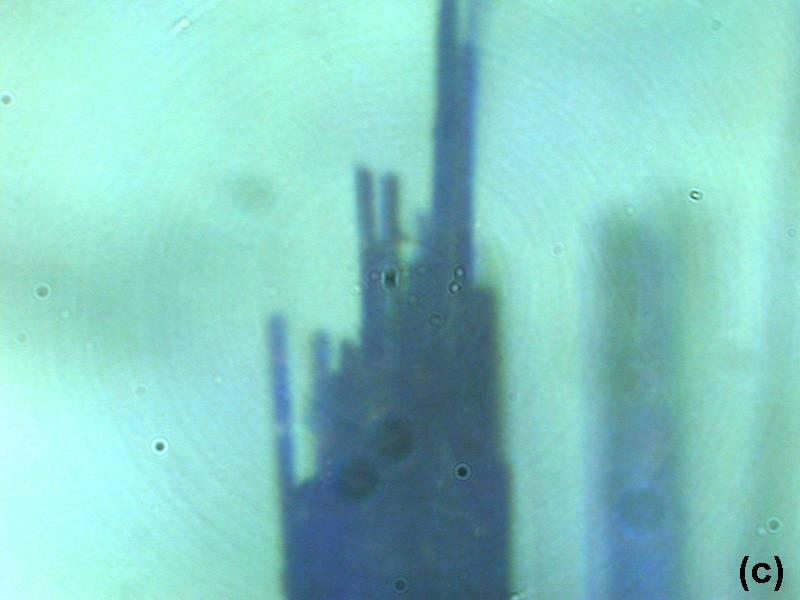
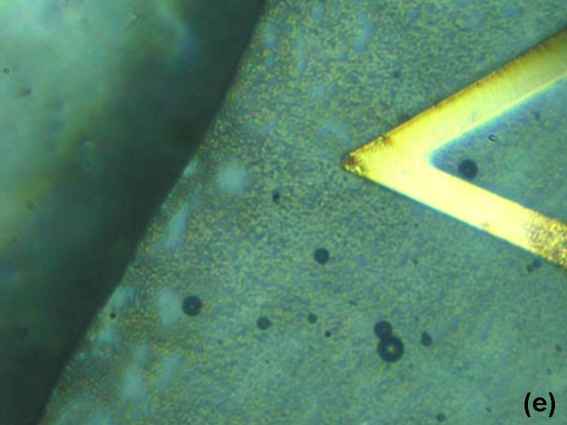
9 ix LIST OF FIGURES Page FIG. 1. Effect of friction on contact area... 5 FIG. 2. Schematic diagram of the JKR Apparatus FIG. 3. Schematic diagram of the Surface Force Apparatus FIG. 4. Measurement of the deflection of the cantilever tip FIG. 5. Measurement of lateral forces using Atomic Force Microscope FIG. 6. Motion of the tip over the surface in force mode FIG. 7. Figures showing the protocol of gluing the particles to the cantilever FIG. 8. Figures showing different views of the cantilever with particle on it FIG. 9. A figure of the scale used to measure the size of the particles FIG. 10. Software interface for Force mode FIG. 11. A sample force-displacement curve obtained from the software FIG. 12. Contact between two spheres of radii R 1 and R 2 under a normal load P 0.35 FIG. 13. Stress distribution in the contacting spheres FIG. 14. Interaction of a single molecule with an infinite surface FIG. 15. Interaction of a sphere with an infinite surface FIG. 16. Model for rigid particle FIG. 17. Free body diagrams of (a) particle, (b) cantilever and (c) surface FIG. 18. Figure to show the (a) undeformed and (b) deformed particle FIG. 19. Plot of pull-off force vs. particle size FIG. 20. Cantilever with particle. The cantilever had excess glue on the bottom face... 50
10 x Page FIG. 21. Pull-off force Vs. Frequency for a particle of diameter µm FIG. 22. Pull-off Force Vs. Frequency for particles of varying sizes FIG. 23. Plot of the constant Pull-off force/ Particle size Vs. Frequency... 53
11 1 CHAPTER I INTRODUCTION 1.1 Micro-particle pull-off: Introduction and applications The interaction of micro particles with a surface is of interest to a diverse range of topics relating to powder transport, air pollution and surface contamination. Many industrial processes rely on either the efficiency to remove particles from surfaces or a technique to hold particles in place on a surface. Some examples of such processes are listed here: 1. Semiconductor manufacturing: In Semiconductor industry, one of the primary causes of failure during fabrication is the contamination of semiconductor surfaces by colloidal particles. At present 30-40% of the microprocessor chips manufactured turn out to be defective due to surface contamination (1). Several methods such as solvent baths, sprays, megasonic and brush cleaning are in extensive use for cleaning of these semiconductor surfaces. For the proper functioning of these methods, a thorough understanding of forces of interaction and the underlying mechanism of particle detachment at the fundamental level is required. This thesis follows the style and format of the Journal of Colloid and Interface Science.
12 2 2. Bioaerosol detection and removal: Most medical procedures and equipment require extremely clean environments, which are rid of any bacteria or viruses. These bacteria and viruses need to be removed from all surfaces and from air. Detection and removal of these bacteria from air is critical for complete cleaning of the whole environment. Also for cleaning of the surface a complete understanding of adhesion of these bacteria to any surface in use is necessary. 3. Trace explosives detection: Explosives when being developed require a fine powder of the chemical explosive, in order to burn easily. These powders usually adhere to outside surfaces of the explosive container and other surrounding surfaces. In explosives detection, all surfaces are tested for traces of these explosive powders by chemical means. For the test, the surfaces are wiped for any powders using a paper and then this paper is checked for traces of the explosive. In order to understand this process fully, a thorough understanding of the particle adhesion to various surfaces is necessary. 4. Pressure Sensitive Adhesives: Pressure sensitive adhesives can be defined as a category of adhesive tapes that in dry form are aggressive and permanently tacky at room temperatures. These will adhere to a surface when applied with pressure and do not require activation by water hear or solvents. These properties are obtained by mixing high molecular weight elastomers with small bulky molecules called tackifiers. Therefore, to study the mechanism
13 3 of tackification an understanding of its interaction with any surface is required. Such studies were previously done using AFM (2). 5. Pharmaceuticals: Drugs are most commonly developed and stored as powders. These powders need to be stored under controlled conditions so that they do not react with the surrounding medium. Also these particles should be readily released when consumed. A great level of understanding of particle interaction between drug particles and various plastic and biological surfaces at various conditions like temperature, humidity and chemical conditions is necessary for drugs to function normally. Particle studies for pharmaceutical applications were made previously (3, 4). 6. Membrane filtration: The use of membranes to separate solutes from liquids is a recent development in process engineering and environmental protection. These advanced filtration processes use polymeric or organic films as membranes. In these processes, the deposition of solutes or dispersed materials on the membrane surface, membrane fowling, plays an important role in determining the overall process performance (5). Such deposits are often colloidal in nature and thus the study of adhesive properties of these materials is necessary. 7. Xerography: The usual process of making copies involves a multistage process. The toner is first transferred from a toner reservoir to a rotating photoconductive layer, where it should adhere to places depending on the copy to be made. Subsequently the particles are transferred to a rotating
14 4 rubber transport belt and finally onto clean paper, where it is fused by applying pressure and elevated temperatures. Therefore in order to achieve an optimal copy, the adhesion of toner particles to various surfaces must be carefully tuned (6). Thus the study of toner particle interactions with various surfaces involved, at the working temperature ranges is necessary for the process to work successfully. (include figure if necessary) 8. Petroleum industry: In petroleum industry, the problem of particles getting trapped in fluid flow is encountered. During the production of crude oil, colloidal particles become entrained in the flowing fluid near the wellbore and plug constricted pore channels of the oil bearing rock formations. This can dramatically reduce the permeability of the flowing hydrocarbons (1). Many surfactants are often used to prevent colloidal particles from becoming entrained. For the formation of these surfactants, the study of particle detachment mechanism in these fluids becomes extremely important. 1.2 Various factors affecting pull-off There are many factors that affect the pull-off of particles from surfaces. These factors pertain to the particle, the surface, the fluid medium and the environment. Each of these factors might be more important than any other in different cases. Many studies have been made studying the importance of these factors.
. This is seen in Fig. 1 below.")
15 5 1. Surface roughness: At the submicron scale, surface topography becomes extremely important. Machined surfaces are not flat, and surface roughness is known to decrease particle adhesion by reducing the contact area (7). This is seen in Fig. 1 below. Many measurements of particle adhesion over rough surfaces have been made (8-12). In a comparison of AFM tip pull-off over peaks and valleys in a rough surface (5), it was found that the pull-off force was much smaller at the peak than the valley. The surface roughness of the particle also might play an important role in the adhesion. Material inhomogeneities also play an important part in particle adhesion (12). FIG. 1. Effect of friction on contact area. (a) smooth surface and (b) rough surface.
16 6 2. Material of the particle and the surface: The adhesion is directly dependent on various material properties. The molecular density of the material directly determines the Van der Waals force of adhesion (13). The surface energy dictates the force of adhesion between the particle and the surface. The elastic modulus of the materials dictates how much the particle and the surface will deform under the action of adhesive forces (14). 3. The fluid medium: Many practical applications require the study of particle adhesion in different fluid media, because many times the adhesion occurs inside a fluid medium, rather than in air. The properties of the fluid surrounding the particle and the surface affect the pull-off. The properties like fluid surface energy, ionic strength, the PH value (1, 10) and surface tension (4) of the fluid play a part in the adhesion. 4. Humidity: The effect of humidity on adhesion is necessary for applications which are not always confined to closed and controlled environments. Humidity affects on particle adhesion have been studied (15). This study was made using the surface force apparatus on mica over rough gold films. It revealed that the pull-off force increased with relative humidity. 5. Temperature: The effect of temperature is of particular importance to pharmaceutical applications. The adhesion of particles is strongly influenced by the viscoelastic property of the particle material (16) and the elasticity of a material is affected by temperature. Temperature effects have been studied in previous work (3). In this work, the adhesion properties of
17 7 polyethyleneglycol 4000 and heavy precipitated calcium carbonate particles to a characterized stainless steel surface at various temperatures. It was observed that the median adhesion force increased with increase in temperature. 6. Size of the particle: The particle size directly influences the force of adhesion due to Van der Waals energies (13). The contact area between the particle and the surface, which directly influences the adhesion force due to surface energy (17, 18), is also dependent on the particle size. Effect of particle size is studied in (19). 1.3 Importance of pull-off velocity and force duration on pull-off Suspension or resuspension of particles exposed to a moving fluid is a common occurrence in nature. In many applications the removal of particles from a surface occurs by perturbations due to fluid flow. Therefore the particle detachment mechanism will not necessarily be by the application of a static pull-off force, perpendicular to the surface. These forces may be at an angle to the surface. In addition these forces might be changing in intensity and direction with time. The dynamic effects of particle detachments need to be studied in order to completely understand the resuspension of particles in moving fluid. Critical components of study of dynamic effects are pull-off velocity and duration of application of the pull-off force. In order to completely understand the dynamic effects, these aspects of particle suspension need to be studied.
18 8 1.4 Theory Physical interactions between macroscopic bodies or molecules are primarily described by interaction energies. They can also be described in terms of forces, which can be measured directly as described in the next section. The forces between particles and surfaces can be calculated on the basis of pair wise additive intermolecular forces. By adding up these pair wise interaction forces of interacting macroscopic bodies for various geometries, such as flat parallel surfaces, spheres, cylinders or combination of these geometries (13), the net interaction energies and the corresponding forces can be expressed in a closed form, using geometrical parameters such as radius and separation distance. However the form of intermolecular potential and the number density of the interacting molecules must be known for the materials. There are various theories that predict the pull-off of particles. Some of these theories are discussed in chapter 4 of this thesis. 1.5 Introduction to force measurement methods The adhesion forces between surfaces and particles can me measured directly by various methods like Sensitive force transducers in contact mechanics (JKR apparatus), Surface force apparatus and Atomic force Microscope etc. Some of them are described below.
19 9 JKR apparatus for force measurements in contact mechanics (20): This apparatus is used to measure the adhesion force between a particle and a surface in contact. The apparatus is illustrated in Fig 2. Essentially it consists of a lower sample holder, which is placed on a balance to measure the load (force) on the sample. The upper sample holder is connected to a precision translation stage. This stage interfaces with the host computer to get commands and send displacement information measured by a displacement sensor. This apparatus can be sealed in a thermal and humidity control chamber. The contact diameter between the samples is measured by a camera placed on top of the upper sample. To conduct the experiments, the upper sample is brought close to the lower sample at controlled speed. When the distance becomes comparable to the range of intermolecular forces, the surfaces jump into contact. At this point the displacement counter can be set to zero. This position shows a negative reading on the balance. Now the sample can be moved down to any specified distance and radius of contact and load readings can be taken at each displacement. Then the sample is again moved up and radius of contact and load at each value of displacement are measured. The snap off will occur at a negative displacement. The load value at snap off can be noted as the adhesion force.
20 10 FIG. 2. Schematic diagram of the JKR Apparatus. The process of bringing the sample up can be done at various speeds to study the dynamic effects of unloading. This apparatus can also used to measure the surface energy of the surfaces by maintaining the contact in equilibrium state during loading process. The drawback of this method being that it cannot be used for micron size particles. The optical resolutions and load measuring mechanism are suitable only for macroscopic bodies.
21 11 Surface force apparatus (13): In the surface force apparatus, the force between two surfaces in controlled vapors or immersed in liquids can be directly measured. A schematic of the apparatus is shown in Fig. 3. The distance resolution is about 0.1 nm and the force sensitivity is about 10-8 N. The SFA essentially consists of two curved molecularly smooth surfaces of mica of radius R 1 cm, between which the interaction forces are measured using a variety of interchangeable force measuring springs. The separation between the two surfaces is measured by optical means, based on interference fringes. The distance between the two surfaces is controlled by the use of a three stage mechanism of increasing sensitivity. The coarse control (upper rod) allows positioning to within 1 µm, the medium control (lower rod) allows positioning to about 1 nm and finally the piezoelectric crystal tube is used for positioning to 0.1 nm. Now force between the surfaces can be measured by expanding or contracting the piezoelectric crystal by a known amount and then measuring optically how much the surfaces actually moved. The difference when multiplied with the stiffness of the force measuring spring gives the force. Modified versions have been developed, which have extended the SFA method to opaque materials, replacing the optical technique for measuring distance by a capacitance method, the overall accuracy remaining the same. Again this apparatus is not suitable for micron size particles.
: AFM was invented in 1980s (21) as a technique for imaging surface topography from micrometer to nanometer length scales.")
22 12 FIG. 3. Schematic diagram of the Surface Force Apparatus. Atomic Force Microscope (AFM): AFM was invented in 1980s (21) as a technique for imaging surface topography from micrometer to nanometer length scales. At the same time, the apparatus allows one to measure forces, precisely and accurately, in various liquid and gaseous media and at controlled temperatures. Thus AFM is an excellent method to characterize surface topography of various surfaces and to quantitatively study the micro-particle adhesion forces for these
23 13 surfaces. The current work applies the principles of the AFM to particle adhesion studies. The principle of working of the Atomic Force Microscope is measuring the forces between a sharp pyramidal tip and the sample surface. The tip is attached to a cantilever spring. This tip is usually raster scanned over the surface to record the surface topography. The topography can be imaged with a sub-nanometer resolution. To do adhesion measurements, the tip is moved over the surface perpendicular to it. The deflection (force) of the cantilever can be recorded as a function of the cantilever displacement over the surface. This plot is known as force-displacement curve. Detailed working and apparatus has been described in section 3.1. Now if a particle is attached to the bottom face of the cantilever spring, in place of the tip and the experiment is conducted in a similar fashion as described above, the force of adhesion of the particle to the surface can be measured. This procedure was used to conduct the experiments in this work.
24 14 CHAPTER II OVERALL SCOPE AND OBJECTIVES 2.1 Overall Scope In the study of microparticle adhesion to surfaces, various factors explained in section 1.2 are of importance. Using the AFM, many of these factors can be studied. The tests can be done for various surfaces of different roughness and compositions. AFM allows tests to be conducted in various media like open air, gases and fluids. For testing with fluid medium, a special apparatus called the fluid cell is used. Additionally, the humidity and temperature of the surface and the environment can be controlled by external means. The process of attaching the particles to cantilevers enables us to study the pull-off forces required for these particles on various surfaces in controlled conditions. Particles of different materials and sizes can be tested on. The roughness of the particles will vary with the composition of the particle material. Lateral forces i.e. forces required to move the tip parallel to the surface can be measured using the AFM. These studies can be carried out by measuring the torsional deflection of the cantilever tip.
25 Objectives The work in this thesis concentrates on the effects of pull-off velocity and force duration on pull-off force. This work is necessary to study the dynamic effects of particle pull-off. In this work, Polystyrene particles of sizes ranging from 6 microns to 25 microns have been attached to cantilever tips and tests have been conducted on stainless steel surfaces. To test the effect of pull-off velocity, these tests were done at varying frequencies, ranging from 1 Hz to 30 Hz. This frequency is limited by the working frequency of the equipment. The results of these tests will be compared with the models available in previous literature and conclusions will be made.
26 16 CHAPTER III MEASURING MICROPARTICLE PULL-OFF USING ATOMIC FORCE MICROSCOPY 3.1 Description of the Atomic Force Microscope (AFM) Since its invention in 1986 (21), the AFM has been a useful tool for imaging surface topography and adhesion force measurements in various gaseous and liquid media and at controlled temperatures. It was invented as an application of the Scanning Tunneling Microscope (STM) (22). STM relies on tunneling current between the probe and the sample to sense the topography of the sample. A sharp metal tip (in best case, atomically sharp), is positioned a few atomic diameters above a conducting sample, which is electrically biased with respect to the tip. At a distance of under 1 nanometer, a tunneling current will flow from the sample to the tip. This tunneling current varies exponentially with the tip-sample separation. Thus by sensing the tunneling current, the sample separation can be estimated from the exponential relation between the current and the separation. The use of this method is however limited to conducting materials. The AFM works by monitoring the elastic deformation of a cantilever spring as it is moved over the surface, following various profiles. This deformation of the cantilever is monitored by a measuring the movement of a laser which is directed to
27 17 a sensor, after reflecting from the top surface of the cantilever, as shown in Fig. 4. This sensor gives the output in volts. FIG. 4. Measurement of the deflection of the cantilever tip. AFM for imaging surface topography: The most widely used application of the AFM is to image the surface topography. For this, the cantilever with the tip is raster scanned over the surface, parallel to the surface. As it moves over the surface, the deformations on the surface cause the tip to deflect up or down depending on whether the formation is a peak or valley. These deflections of the cantilever are noted at each point over the surface and thus by techniques of raster scan, the whole surface can be imaged. AFM for measuring lateral forces: To measure the lateral forces to move the tip over the surface, the torsional stiffness of the cantilever tip needs to be known.
28 18 The tip can be moved over the surface, parallel to the surface and as it moves, the movement of the laser beam in the horizontal direction can be noted. This horizontal movement of the laser can be related to the deflection angle of the tip. This deflection angle is a measure of the lateral force required to move the tip. This is seen in Fig. 5. FIG. 5. Measurement of lateral forces using Atomic Force Microscope. AFM for measuring pull-off forces: Measurement of pull-off forces using AFM can be achieved by moving the cantilever up and down, perpendicular to the surface being tested. The deflections of the tip are noted at each position of the tip over the surface, by measuring the movement of the laser on the sensor. The process of the cantilever approaching the surface is called extending and that of moving away from the surface is called retracting. This sequence is shown in detail in Fig. 6 and described below. 1. Extending: The tip first approaches the substrate with no cantilever deflection ( ab of the Fig. 6). At some critical separation distance, the
29 19 cantilever snaps to contact and is deflected downwards ( bc in the Fig. 6). As the cantilever continues to approach the substrate, it is pressed down against the substrate and deflects upwards ( cd in the Fig. 6). 2. Retracting: When the tip is pulled away from the surface, the upward deflection of the cantilever is reduced ( de in the Fig. 6). Beyond the equilibrium point (labeled e ), the cantilever continues to be deflected downwards as an upward force is applied. This is seen in ef in Fig. 6. At point f, the deflection of the cantilever causes enough upward force to pull-off the tip from the surface. Therefore at this point, the tip snaps off from the surface as seen in fg in figure 2. Thereafter, the cantilever moves over the tip without any deflection, seen in gh. FIG. 6. Motion of the tip over the surface in force mode.
30 20 This sequence of extending and retracting is repeated over the surface at desired frequency to get a plot of deflection of the tip vs. the displacement of the tip seen in the Fig. 6 above. The deflection fg, corresponding to the snap off when multiplied with the stiffness of the cantilever, gives the required pull-off force. 3.2 Materials and apparatus Particles: The particles used in this study were Polystyrene spheres. These particles were obtained from Duke Scientific. The size range of the particles is 1 to 50 microns. Substrate: The surface used to conduct the experiment was a 430 stainless steel surface (Ted Pella Inc.). Atomic Force Microscope: The AFM used here is a Digital Instruments Nanoscope IIIa Scanning Probe Microscope, equipped with a J scanner. The instrument produces x and y motion by movement of the tip over the surface, using a manual manipulator and z motion by movement of the substrate, using a piezo electric controller. It is equipped with digital camera, which gives continuous streaming video output to an independent monitor. The images from this camera have a total maximum magnification of 1000X. This camera is also capable of taking still images. Cantilever Tips: The cantilever tips used in the experiments were obtained from Veeco Systems. These are Silicon Nitride tips. The cantilevers have gold coating on top for better reflection. These cantilevers come in four sizes, lengths
31 and 200 micron, widths 40 micron (wide) and 15 micron (narrow). The spring constants of the cantilevers are specified by the manufacturer and are given in Table 1. TABLE 1 Cantilever stiffness values Cantilever type Stiffness (N/m) 100 microns wide legs microns narrow legs microns wide legs microns narrow legs.06 Adhesive: The selection of the adhesive used to glue the particles to the cantilever tips is critical. The glue used for this operation in our work is LOCTITE QuickTite R from Manco Inc Adhesion of particles to cantilevers The process of making the force-distance measurements on particles using AFM was first done by Ducker et al. in 1991 (23). They had made these measurements for silica particles. Subsequent work with an AFM using microparticles has been used to study numerous processes and applications (4, 5, 8, 9, 10, 12, 24-31). The selection of adhesives and the process used are described in these works. The choice of the adhesive depends, among other things, on the nature
32 22 of the particle material, the experimental medium (liquid or air), the cantilever material, the temperature at which the experiment is conducted and on the method of fastening. Detailed fastening procedure is described by claesson et al. (32). Essentially a micromanipulator or an XYZ-translation stage is used to attach particles to a cantilever. First, a small amount of heat-sensitive adhesive is warmed up. The end of a small wire is brought into contact with the adhesive by means of the XYZtranslation stage. The amount of glue is then reduced by repeatedly touching it with the dry parts of the glass slide. Then it is transferred to the end of a cantilever which is heated on a hot plate. Finally a second wire covered with particles is brought into contact with the cantilever. Rolling of the particle in the adhesive should be prevented in this step and the cantilever should be removed from the hotplate immediately. These operations take place under an optical microscope. In our work, a different protocol was designed for attaching particles to cantilever tips. The key steps involved in this protocol are: 1. Putting a controlled amount of glue in the vicinity of the particle and 2. Moving the tip rapidly to over the glue and then over to the particle, before the glue dries. To accomplish the first task, a right combination of the glue and a glue carrying medium is required. Carbon fibers of submicron diameters were chosen to carry the glue to the required place near the chosen particle. These fibers were wound together to make a strand of about 15 microns diameter. This was found
33 23 useful because this strand absorbed any excess glue and only dispersed small amounts of glue when touched over the surface. The glue chosen was QuickTite R from LOCTITE. This glue was chosen because it was of desired viscosity and the setting time was around 20 seconds which was enough for completion of all the steps involved. To move the cantilever rapidly between the glue and the particle, essentially a micromanipulator or a XYZ-translation stage is required. For this purpose, the mounting stage provided with the AFM was found satisfactory as the cantilever could be rigidly mounted on it and moved over the stage in X, Y and Z directions. To glue the particles, the following protocol is observed 1. A big selection of the particles is spread on a glass slide. A jet of dry Nitrogen is blown over the slide so that any lumps of particles are removed and the particles get dry. This slide is now kept under the microscope. (Fig. 7a) 2. By moving the slide around, a particle of required size is selected. 3. Now the cantilever is mounted in its seat and by the use of the translation stage, it is brought near the selected particle. (Fig 7b) 4. A small amount of glue is put upon the carbon fibers. The carbon fibers absorb any excess glue and only a small amount of glue is present on the surface. Carbon fibers used here are seen in Fig. 7c. 5. This glue tipped carbon fiber strand is brought in the vicinity of the selected particle and the tip. This fiber is touched to the glass slide and a small
34 24 amount of glue is deposited near the particle (Fig. 7d). It is critical that the glue does not engulf the particle and the tip. To ensure this, the selection of the carbon fibers was made. 6. Now the cantilever is moved rapidly over to the glue on the glass slide and brought down so that a small amount of glue is deposited on the bottom side of the cantilever. Again it needs to be ensured that the cantilever does not get into too much contact with the glue and get excess glue, which will engulf the particle, or get glue on the top surface, which will hamper the reflection of laser from the top surface of the cantilever. Also if it gets too much glue onto it, the stiffness of the cantilever might change by a huge margin which is unacceptable. 7. Now this cantilever with the glue on its bottom face is moved over to the selected particle and brought into contact with the top of the particle (Fig. 7e). It is now allowed to stay in this position for some time so that the glue hardens and a bond is formed. The cantilever, with the particle, is now lifted up from the glass slide. 8. A jet of dry nitrogen is blown over the cantilever and if the particle stays on the cantilever, it is assumed that the bonding is good. 9. The cantilever with the particle is now stored in a closed container for around 24 hours so that the glue solidifies completely.
 Particles spread out on a glass plate, (b) The cantilever brought near the selected particle using the precision translation stage, (c) The strand made using carbon fibers of sub-micron diameter,")
35 25 FIG. 7. Figures showing the protocol of gluing the particles to the cantilever. (a) Particles spread out on a glass plate, (b) The cantilever brought near the selected particle using the precision translation stage, (c) The strand made using carbon fibers of sub-micron diameter, (d) A blob of glue deposited near the particle and (e) The cantilever lowered onto the particle after getting the glue on its lower surface.

36 26 FIG. 7. Continued

37 27 FIG. 7. Continued

 Cantilever is horizontal and (b) Cantilever is")
38 28 FIG. 8. Figures showing different views of the cantilever with particle on it. (a) Cantilever is horizontal and (b) Cantilever is held at an angle to the vertical axis to show the depth of the particle

39 29 FIG. 9. A figure of the scale used to measure the size of the particles. The smallest unit on the scale is 50 µm. This tip with particle is now ready to do experiments upon. Some views of the cantilever with the particle are seen in Figs. 8a and 8b. The size of the particle can be measured by using a scale, whose smallest unit is 50 µm. To measure the size, an image of the particle is taken using the camera provided with the microscope and at the same magnification, an image of the scale is also taken. Now by measuring the length of the both the particle and the smallest unit on the scale, and then taking their ratio, the size of the particle can be determined. An image of the scale used here is seen in Fig. 9.

40 Experimental procedure The main interface between the user and the AFM is through the software provided with the AFM. This software allows the user to use the instrument in many modes. The mode required for the required measurements is contact mode. The software interface for contact mode can be seen in Fig. 10 below. FIG. 10. Software interface for Force mode.
41 31 The surface to be tested is first cleaned with acetone so that it is rid of all dirt, oils and coatings. It is now dried with a jet of dry Nitrogen and placed on the XYZ-translation stage of the AFM. The cantilever with the particle on its tip is mounted in the tip holder and placed over the surface to be tested so that the bottom of the particle is about 1 mm above the surface. The laser is now directed to the tip of the cantilever. This is reflected to the light detection sensor. The sensor is moved up or down to get the reflection to the center of the sensor. This is seen as 0 Volts reading from the sensor. The engage command is given to the software now. This starts to move the tip down steadily till the reading from the sensor reaches a pre-determined set-point voltage, which tells the software that engagement with the surface has occurred. This voltage is generally set to 2 V above the value which the sensor showed when the tip was stationary. This value of 2 V was determined by trial and error. For softer materials, the set-point needs to be higher to detect engagement with the surface. When the software shows that engagement with the surface is done, it needs to be given a force mode command. This command turns it to the mode which gives the force-displacement curves as output. Now the output from the software shows the force-displacement curves for the given particle. One sample output can be seen in Fig. 11. These curves can be stored to the system disk using the capture command.

42 32 FIG. 11. A sample force-displacement curve obtained from the software. The main aim of the experiments is to measure the pull-off force at various pull-off velocities. The pull-off velocity of the particle is directly proportional to the frequency at which the extending and retracting cycle is repeated. In the software, there is a provision to change this frequency. Now for each particle, the experiment is conducted at varying frequencies and the force-displacement plot is saved for each frequency. From these plots, the force is calculated for each frequency, by multiplying the maximum deflection with the spring constant. These forces can now be plotted with respect to frequency.
43 33 CHAPTER IV PREVIOUS THEORIES AND MODELS 4.1 Introduction to various theories Various theories predict adhesion force of particles over surfaces. There are mainly two types of forces. Contact forces and short range (molecular) forces. Contact has been studied in detail in previous works (17, 18, 33-36). The Hertz theory calculated the shape and size of the zone of contact due to the elastic deformation of two bodies in contact. The JKR and DMT theories start with the Hertz contact and consider the effects of adhesion force on the deformation of the sphere to determine the contact area and pull-off force. Molecular forces arise due to various properties of molecules (13). Coulomb forces act between charged particles. Electrostatic interactions due to dipole moments act on polarized molecules in presence of electric fields emanating from nearby molecules. In addition to these forces, some forces act between all molecules, even totally neutral ones. These are most commonly referred to as dispersion forces. These contribute the most to Van der Waals forces as they are always present, irrespective of the type of molecule.
44 JKR theory This work was published in It attempts to include the effect of adhesion force on the deformation of two elastic spheres in contact. According to Hertz theory, two spheres of radii R 1 and R 2 pressed together under a load P 0 will have a contact radius a 0, shown in Fig. 12, given by 3 3 RR a0 = π ( k + k ) P 4 R + R , where 2 1 ν ki = ι π Ei Two distant points in the spheres approach each other by an amount δ given by R1+ R2 2 π ( k1 k2) P0 1 2 δ = + 16 RR But the equations of Hertz contact are not valid when adhesive forces act between the two bodies. It is assumed that the contact radius will increase to a 1 as shown in Fig. 12, because of the adhesive forces. The total load increases to P 1, because of an additional load due to adhesion (called the Hertz load). It assumes a stress distribution as shown in curve B in Fig. 13. This distribution assumes compressive stress in the center and tensile stress near the contact boundary. The curves A and C are Hertz stress for contact radii a 1 and a 0 respectively.
45 35 FIG. 12. Contact between two spheres of radii R 1 and R 2 under a normal load P 0. The dotted line is contact assumed by Hertz and solid line is contact given by JKR theory. FIG. 13. Stress distribution in the contacting spheres. Distribution A is Hertz stress with contact radius a 0, B is the actual distribution assumed in JKR theory and C is Hertz stress with contact radius a 1.
46 36 Essentially, equilibrium between these two spheres will be attained when the differential of the total energy in the system U T with respect to the contact radius a will reach zero. Total energy is the sum of three terms, the stored elastic energy, the mechanical energy in the applied load and the surface energy. On calculation, for two spheres of same material, this total energy U T is found to be 1 UT = 1 P 1 + PP 1 1 PP 2 + PP γ ( RP K K R K R [ ] [ ] π 1/ ) where, R = RR 1 2/ ( R1+ R2) γ is the surface energy of both the spheres 4 K = 3 π ( k + k ) 1 2. P1 and P 0 are as defined before. Now for equilibrium, dut / da 1 = 0, which is equivalent to dut / dp 1 = 0. This on simplification gives P = P + 3 γπ R+ ( P + 3 γπ R) P RP Therefore the contact radius a which is defined as a 3 =, is given by K 3 R 2 a = [ P+ 3γπ R+ 6 γπ RP+ (3 γπ R) ] K
47 37 Now as the load P is reduced, a decreases. For real solution to be obtained for this equation, P has to be greater than 3 γπ R. This implies that separation will 2 occur at 3 P= γπ R 2 This is the pull-off force required to separate a particle of radius R given by JKR theory. The negative sign just signifies that the force is in upward direction. 4.3 DMT theory The DMT theory takes into account the interaction forces outside the contact area. But these interaction forces are assumed not to deform the profile, which remains Hertzian. It is assumed that pull-off occurs at zero contact radius. The important results of this theory are given here. The contact radius of the sphere with the surface under zero load is given by a πγ R = where γ is the surface energy of both the surfaces, R is the radius of K the sphere and K is defined as The pull-off force, reached at zero contact radius is given by Fpull off = 2πγ R where, γ is the surface energy of the particle and the surface and R is the radius of the sphere.
48 Calculation of interaction due to Van der Waals forces In this section, the total interaction force between a particle and a surface is found using the principle of addition of the interaction forces. According to the theory developed on the basis of dipole-induced dipole interactions for neutral molecules, the energy of interaction between two molecules is given by [ref] 2 3α0 hν W() r = 4(4 π ) r 0 2 6, where α0 is the polarizability of the Bohr atoms, h is the Planks constant, ν is the orbiting frequency of the electron, 0 is the permittivity of free space and r is the distance between the two molecules. To find the interaction between a particle and a surface, we first integrate this energy of interaction over the surface to get the interaction between a molecule and the surface and then integrate over all the molecules in the particle to get the n total interaction. For convenience, it is assumed that W( r) = C/ r. Consider the surface to be composed of circular rings of cross sectional area dx*dz and radius x as shown in Fig. 14. The total volume of the ring is 2π xdxdz, and the number of molecules in the ring will be 2πρ xdxdz where ρ is the number density of the molecules in the surface.
49 39 FIG. 14. Interaction of a single molecule with an infinite surface. The surface is assumed to be composed of rings of radius x at a distance of z from the molecule. The net interaction energy of a single molecule at a distance D from the surface will be given by, z= x= W( D) = 2πCρ dz z= D x= 0 xdx ( z + x ) 2 2 n/2 2πCρ dz = = 2 πcρ/( n 2)( n 3) D n 2 ( n 2) z D Using this interaction between a molecule and a surface, we go do the calculation for a large sphere of radius R and the surface. Consider the sphere to be n 3
50 40 composed of solid rings of thickness dz at a distance D+ zand of radius x, as shown in Fig. 15. FIG. 15. Interaction of a sphere with an infinite surface. The sphere is assumed to be composed of solid disks of thickness dz at a distance D+z from the surface. From the chord theorem, we have x 2 = (2 R z) z. The volume of the thin 2 disc isπx dz = π( zr z) zdz. Therefore the number of molecules in the disc is πρ( zr z) zdz, where ρ is the density of molecules in the sphere material. As all these molecules are at a distance( D+ z), we have the interaction energy as, 2 2 z= 2R 2 π ρ (2 ) C R z zdz W( D) = n 3 ( n 2)( n 3) ( D+ z) z= 0 For D<<R, only small values of z contribute to the integral. Therefore, 2 2 2π Cρ 2 Rzdz W( D) = ( n 2)( n 3) ( D+ z) n 0 3
51 π Cρ R = ( n 2)( n 3)( n 4)( n 5) D n For n=6, as we had started, W( D) = π Cρ R/6D. This is the interaction potential between a sphere of radius R and a surface. The force of interaction is given by F = W( D)/ D. Therefore = π ρ /6, where F C R D 2 3α 0 hν C = 4(4 π ) 0 2 ρ is the molecule number density of the sphere and surface materials. R is the radius of the sphere D is the distance between the surface and the point in the sphere, nearest to the surface. Therefore, the force of interaction between a sphere and a surface is given by = π ρ /6. F C R D 4.5 Model for deformable bodies The model currently being developed is a lumped mass model as shown in Fig. 16. The cantilever is replaced by a spring of spring constant K 3 and an equivalent mass M 3. The particle is approximated by the mass M 2 and a spring of stiffness K 2. The surface can be replaced by a spring K 1 and an equivalent mass M 1. The springs associated with the particle and the surface are to account for the compliance of the materials these are made up of.
52 42 FIG. 16. Model for rigid particle. The force between the particle and the surface (F v ) is approximated by Van der Waals adhesion forces, given by F = π Cρ R/6D. These forces have been derived and explained in detail in section 4.4. The end of the cantilever can be given any arbitrary motion U(t). The equations of motion for the masses M 1, M 2 and M 3 can be generated from basic kinematics. The explicit differential equations for the motion of the system are derived as explained below. Considering the free body diagrams of the particle, the surface and the spring respectively, as shown in Fig. 17,
53 43 FIG. 17. Free body diagrams of (a) particle, (b) cantilever and (c) surface... mx= F K( x L) 1 1 v m x = F + K x = F + K (( x x ) L ) 2 2 v 2 2 v m x = K (( x x ) L ) K (( x x ) L ) Where L 1, L 2 and L 3 are the natural lengths of the three springs and rest of the parameters are as explained above. For practical purposes, the stiffness of the surface can be neglected as it is assumed to be rigid in comparison to the particle. The stiffness and equivalent mass of both the cantilever and the particle need to be determined in order to be used in the model. The stiffness of the cantilever is provided by the manufacturer. This value is taken as a standard. The equivalent mass of the cantilever can be found by finding its natural frequency. The natural frequency is found by using the sweep command in tapping mode in AFM. The natural frequency of the cantilever is given k K byω n = and thus mass is given by m =. 2 m ω n
54 44 The mass of the particle can be calculated by multiplying the density of the particle material with its volume. As the particle is a sphere, its volume is given by V = π R and thus the mass is M = π R ρ, where ρ is the density of the particle material. To find the equivalent stiffness of the particle, calculations are made for a sphere using Lagrangian approach for its strain energy. This derivation is shown in section Calculation of stiffness for spherical particle To calculate the equivalent stiffness of the particle due to its compliance, we take the problem as follows. Let the un-deformed sphere have a radius R. After deformation, we assume that the sphere becomes an ellipsoid with vertical dimension R(1+a) and the horizontal dimension R(1+b). This can be seen in Fig 18. FIG. 18. Figure to show the (a) undeformed and (b) deformed particle. The deformation gradient matrix for this configuration is given by:
55 45 a F = 0 b b + 1 And a 0 0 u = F I = 0 b b Where u is the displacement of a point in the body. Infinitesimal strain (ε ) is given by, a [ T ε = u+ u ] = 0 b b For isotropic materials, the stress (σ ) in the body for a given strain (ε ) is given by the equation: σ = 2 µε + λtr( ε ) I Where µ and λ are Lame s constants, given in terms of the Young s modulus ( E ) and Poisson s ratio (ν ) as E µ = 2(1 + ν ) Eν And λ = (1 + ν )(1 2 ν ) So for this configuration, stress matrix is given by: 2 µ a+ λ( a+ 2 b) 0 0 σ = 0 2 µ b+ λ( a+ 2 b) µ b+ λ( a+ 2 b) The strain energy of a body with stress σ and strain ε is given by:
56 46 U 1 = σε ij ijdv 2 V Where V is the volume of the body. Now for the given particle with given stress σ and strainε, σijε ij = µ a + λ a+ b a + µ b + λ a+ b b + µ b + λ a+ b b (2 ( 2 ) ) (2 ( 2 ) ) (2 ( 2 ) ) = 2 µ ( a + 2 b ) + λ( a+ 2 b) Therefore, taking the reference volume of the sphere as V 4 3 R 3 = π, we get 2 U = π (2 µ ( a + 2 b ) + λ ( a+ 2 b ) ) R Now to get the stiffness, we use the Lagrangian approach. Considering, U b = 0 and U a = PR, we can get the stiffness of the particle. U = 0 b 4µ b+ 2 λ( a+ 2 b) = 0 aλ b = 2( µ + λ) And
57 47 U = PR a 2 π (4µ + 2 λ( + 2 )) = µ (2µ + 3 λ) π R a= PR 3 ( λ + µ ) 3 R a a b PR 4 µ (2µ + 3 λ) π R ( ar ) = P 3 ( λ + µ ) Solving for E from equations of λ and µ, we get (2 3 ) E µ µ + = λ ( λ + µ ) Therefore the equivalent stiffness of the spring is given by 4 K = π RE 3 Where R is the radius of the un-deformed sphere and E is the Young s modulus of the sphere material. 4.7 Stiffness and mass for a given set of particle and cantilever In this section, some equivalent stiffness and mass calculations are shown for a polystyrene particle of 20 micron diameter and a 100 micron wide cantilever. Mass of particle (M): V 4 = π R M = π R ρ 3
58 48 The density of polystyrene is g/cc. For our case we take it as g/cc. Therefore for a 20 micron particle the mass is M= 4.395*10 Kg or µ g. Equivalent stiffness of particle (K): 4 K = π RE 3 The Young s modulus for Polystyrene is given as 3 GPa. Putting this in the stiffness for a 20 micron particle, we get K= Stiffness of cantilever (k): *10 N/ m This is given as a standard by the manufacturer. Here we take a 100 micron Wide cantilever, whose stiffness is given as k=0.58 N/m Equivalent mass of the cantilever(m): As described in section 4.5, natural frequency of a 100 micron wide cantilever is found experimentally using the AFM. The natural frequency was found K to be 1.39 KHz. Now the equivalent mass can be calculated using m = to be ω 2 10 m= 3.07*10 Kg or.307µ g. n
59 49 CHAPTER V RESULTS AND DISCUSSION 5.1 Pull-off forces for particles of various sizes at a single frequency There are two variables which affecting pull-off force that are studied in this work. These are particle size and frequency of pull-off. First we study the effect of particle size on the pull-off force. For this, the experiments were conducted at a constant frequency for many particles of different sizes. The force-displacement plots were obtained for each particle and from these plots, the pull-off force was calculated for each particle. These pull-off forces were plotted against particle size. This plot is seen in Fig. 19. A line fitting the points on in the plot is drawn on the plot with Y intercept set as zero. The slope of this line is found to be 5.85 (nn/µm). Therefore the equation for pull-off force with particle size can be written as F=5.85*R, where F is pull-off force and R is the diameter of the particle. There is one anomalous point in the 21 µm range that has a very low pulloff force. On further verification it was found that the cantilever had got excess glue on the bottom. This cantilever can be seen in Fig. 20. This made the cantilever stiffer and thus the deflection of the tip was lower. This deflection when multiplied with the standard stiffness given by the manufacturer, gave a lower force.

60 Pull-off Force (nn) Particle size (µm) FIG. 19. Plot of pull-off force vs. particle size. FIG. 20. Cantilever with particle. The cantilever had excess glue on the bottom face.
Basic Laboratory. Materials Science and Engineering. Atomic Force Microscopy (AFM)
") Basic Laboratory Materials Science and Engineering Atomic Force Microscopy (AFM) M108 Stand: 20.10.2015 Aim: Presentation of an application of the AFM for studying surface morphology. Inhalt 1.Introduction...
Basic Laboratory Materials Science and Engineering Atomic Force Microscopy (AFM) M108 Stand: 20.10.2015 Aim: Presentation of an application of the AFM for studying surface morphology. Inhalt 1.Introduction...
Module 26: Atomic Force Microscopy. Lecture 40: Atomic Force Microscopy 3: Additional Modes of AFM
 Module 26: Atomic Force Microscopy Lecture 40: Atomic Force Microscopy 3: Additional Modes of AFM 1 The AFM apart from generating the information about the topography of the sample features can be used
Lecture 4 Scanning Probe Microscopy (SPM)
") Lecture 4 Scanning Probe Microscopy (SPM) General components of SPM; Tip --- the probe; Cantilever --- the indicator of the tip; Tip-sample interaction --- the feedback system; Scanner --- piezoelectric
Lecture 4 Scanning Probe Microscopy (SPM) General components of SPM; Tip --- the probe; Cantilever --- the indicator of the tip; Tip-sample interaction --- the feedback system; Scanner --- piezoelectric
Instrumentation and Operation
 Instrumentation and Operation 1 STM Instrumentation COMPONENTS sharp metal tip scanning system and control electronics feedback electronics (keeps tunneling current constant) image processing system data
General concept and defining characteristics of AFM. Dina Kudasheva Advisor: Prof. Mary K. Cowman
 General concept and defining characteristics of AFM Dina Kudasheva Advisor: Prof. Mary K. Cowman Overview Introduction History of the SPM invention Technical Capabilities Principles of operation Examples
Chapter 2 Correlation Force Spectroscopy
 Chapter 2 Correlation Force Spectroscopy Correlation Force Spectroscopy: Rationale In principle, the main advantage of correlation force spectroscopy (CFS) over onecantilever atomic force microscopy (AFM)
Contents. Preface XI Symbols and Abbreviations XIII. 1 Introduction 1
 V Contents Preface XI Symbols and Abbreviations XIII 1 Introduction 1 2 Van der Waals Forces 5 2.1 Van der Waals Forces Between Molecules 5 2.1.1 Coulomb Interaction 5 2.1.2 Monopole Dipole Interaction
! Importance of Particle Adhesion! History of Particle Adhesion! Method of measurement of Adhesion! Adhesion Induced Deformation
 ! Importance of Particle Adhesion! History of Particle Adhesion! Method of measurement of Adhesion! Adhesion Induced Deformation! JKR and non-jkr Theory! Role of Electrostatic Forces! Conclusions Books:
Analysis of contact deformation between a coated flat plate and a sphere and its practical application
 Computer Methods and Experimental Measurements for Surface Effects and Contact Mechanics VII 307 Analysis of contact deformation between a coated flat plate and a sphere and its practical application T.
Particle removal in linear shear flow: model prediction and experimental validation
 Particle removal in linear shear flow: model prediction and experimental validation M.L. Zoeteweij, J.C.J. van der Donck and R. Versluis TNO Science and Industry, P.O. Box 155, 600 AD Delft, The Netherlands
Characterization of MEMS Devices
 MEMS: Characterization Characterization of MEMS Devices Prasanna S. Gandhi Assistant Professor, Department of Mechanical Engineering, Indian Institute of Technology, Bombay, Recap Characterization of MEMS
Imaging Methods: Scanning Force Microscopy (SFM / AFM)
") Imaging Methods: Scanning Force Microscopy (SFM / AFM) The atomic force microscope (AFM) probes the surface of a sample with a sharp tip, a couple of microns long and often less than 100 Å in diameter.
Imaging Methods: Scanning Force Microscopy (SFM / AFM) The atomic force microscope (AFM) probes the surface of a sample with a sharp tip, a couple of microns long and often less than 100 Å in diameter.
Atomic Force Microscopy imaging and beyond
 Atomic Force Microscopy imaging and beyond Arif Mumtaz Magnetism and Magnetic Materials Group Department of Physics, QAU Coworkers: Prof. Dr. S.K.Hasanain M. Tariq Khan Alam Imaging and beyond Scanning
STM: Scanning Tunneling Microscope
 STM: Scanning Tunneling Microscope Basic idea STM working principle Schematic representation of the sample-tip tunnel barrier Assume tip and sample described by two infinite plate electrodes Φ t +Φ s =
Scanning Probe Microscopy. Amanda MacMillan, Emmy Gebremichael, & John Shamblin Chem 243: Instrumental Analysis Dr. Robert Corn March 10, 2010
 Scanning Probe Microscopy Amanda MacMillan, Emmy Gebremichael, & John Shamblin Chem 243: Instrumental Analysis Dr. Robert Corn March 10, 2010 Scanning Probe Microscopy High-Resolution Surface Analysis
Atomic and molecular interactions. Scanning probe microscopy.
 Atomic and molecular interactions. Scanning probe microscopy. Balázs Kiss Nanobiotechnology and Single Molecule Research Group, Department of Biophysics and Radiation Biology 27. November 2013. 2 Atomic
Simulation of atomic force microscopy operation via three-dimensional finite element modelling
 IOP PUBLISHING Nanotechnology 20 (2009) 065702 (14pp) NANOTECHNOLOGY doi:10.1088/0957-4484/20/6/065702 Simulation of atomic force microscopy operation via three-dimensional finite element modelling JLChoi
REPORT ON SCANNING TUNNELING MICROSCOPE. Course ME-228 Materials and Structural Property Correlations Course Instructor Prof. M. S.
 REPORT ON SCANNING TUNNELING MICROSCOPE Course ME-228 Materials and Structural Property Correlations Course Instructor Prof. M. S. Bobji Submitted by Ankush Kumar Jaiswal (09371) Abhay Nandan (09301) Sunil
A General Equation for Fitting Contact Area and Friction vs Load Measurements
 Journal of Colloid and Interface Science 211, 395 400 (1999) Article ID jcis.1998.6027, available online at http://www.idealibrary.com on A General Equation for Fitting Contact Area and Friction vs Load
Chapter 10. Nanometrology. Oxford University Press All rights reserved.
 Chapter 10 Nanometrology Oxford University Press 2013. All rights reserved. 1 Introduction Nanometrology is the science of measurement at the nanoscale level. Figure illustrates where nanoscale stands
EE 5344 Introduction to MEMS CHAPTER 6 Mechanical Sensors. 1. Position Displacement x, θ 2. Velocity, speed Kinematic
 I. Mechanical Measurands: 1. Classification of main types: EE 5344 Introduction MEMS CHAPTER 6 Mechanical Sensors 1. Position Displacement x, θ. Velocity, speed Kinematic dx dθ v =, = ω 3. Acceleration
MECH 466. Micro Electromechanical Systems. Laboratory Manual Laboratory #3: Stiction of MEMS and Strength of MEMS Materials
 MECH 466 Micro Electromechanical Systems Laboratory Manual Laboratory #: Stiction of MEMS and Strength of MEMS Materials Department of Mechanical Engineering, University of Victoria N. Dechev, 2011, University
Scanning Tunneling Microscopy
 Scanning Tunneling Microscopy References: 1. G. Binnig, H. Rohrer, C. Gerber, and Weibel, Phys. Rev. Lett. 49, 57 (1982); and ibid 50, 120 (1983). 2. J. Chen, Introduction to Scanning Tunneling Microscopy,
DETERMINATION OF THE ADHESION PROPERTIES OF MICA VIA ATOMIC FORCE SPECTROSCOPY
 2nd International Conference on Ultrafine Grained & Nanostructured Materials (UFGNSM) International Journal of Modern Physics: Conference Series Vol. 5 (2012) 33 40 World Scientific Publishing Company
NIS: what can it be used for?
 AFM @ NIS: what can it be used for? Chiara Manfredotti 011 670 8382/8388/7879 chiara.manfredotti@to.infn.it Skype: khiaram 1 AFM: block scheme In an Atomic Force Microscope (AFM) a micrometric tip attached
STRAIN GAUGES YEDITEPE UNIVERSITY DEPARTMENT OF MECHANICAL ENGINEERING
 STRAIN GAUGES YEDITEPE UNIVERSITY DEPARTMENT OF MECHANICAL ENGINEERING 1 YEDITEPE UNIVERSITY ENGINEERING FACULTY MECHANICAL ENGINEERING LABORATORY 1. Objective: Strain Gauges Know how the change in resistance
TE 75R RESEARCH RUBBER FRICTION TEST MACHINE
 TE 75R RESEARCH RUBBER FRICTION TEST MACHINE Background: The Research Rubber Friction Test Machine offers the ability to investigate fully the frictional behaviour of rubbery materials both in dry and
CHAPTER 4 DESIGN AND ANALYSIS OF CANTILEVER BEAM ELECTROSTATIC ACTUATORS
 61 CHAPTER 4 DESIGN AND ANALYSIS OF CANTILEVER BEAM ELECTROSTATIC ACTUATORS 4.1 INTRODUCTION The analysis of cantilever beams of small dimensions taking into the effect of fringing fields is studied and
MEMS Metrology. Prof. Tianhong Cui ME 8254
 MEMS Metrology Prof. Tianhong Cui ME 8254 What is metrology? Metrology It is the science of weights and measures Refers primarily to the measurements of length, weight, time, etc. Mensuration- A branch
Colloidal Particles at Liquid Interfaces: An Introduction
 1 Colloidal Particles at Liquid Interfaces: An Introduction Bernard P. Binks and Tommy S. Horozov Surfactant and Colloid Group, Department of Chemistry, University of Hull, Hull, HU6 7RX, UK 1.1 Some Basic
Scanning Force Microscopy
 Scanning Force Microscopy Roland Bennewitz Rutherford Physics Building 405 Phone 398-3058 roland.bennewitz@mcgill.ca Scanning Probe is moved along scan lines over a sample surface 1 Force Microscopy Data
DEPOSITION OF THIN TiO 2 FILMS BY DC MAGNETRON SPUTTERING METHOD
 Chapter 4 DEPOSITION OF THIN TiO 2 FILMS BY DC MAGNETRON SPUTTERING METHOD 4.1 INTRODUCTION Sputter deposition process is another old technique being used in modern semiconductor industries. Sputtering
EE C247B / ME C218 INTRODUCTION TO MEMS DESIGN SPRING 2016 C. NGUYEN PROBLEM SET #4
 Issued: Wednesday, March 4, 2016 PROBLEM SET #4 Due: Monday, March 14, 2016, 8:00 a.m. in the EE C247B homework box near 125 Cory. 1. This problem considers bending of a simple cantilever and several methods
Chapter 4. Electrostatic Fields in Matter
 Chapter 4. Electrostatic Fields in Matter 4.1. Polarization 4.2. The Field of a Polarized Object 4.3. The Electric Displacement 4.4. Linear Dielectrics 4.5. Energy in dielectric systems 4.6. Forces on
MATERIALS. Why do things break? Why are some materials stronger than others? Why is steel tough? Why is glass brittle?
 MATERIALS Why do things break? Why are some materials stronger than others? Why is steel tough? Why is glass brittle? What is toughness? strength? brittleness? Elemental material atoms: A. Composition
Chapter 21. Electric Fields
 Chapter 21 Electric Fields The Origin of Electricity The electrical nature of matter is inherent in the atoms of all substances. An atom consists of a small relatively massive nucleus that contains particles
ACOUSTIC EMISSION CHARACTERISTICS OF SURFACE FRICTION IN BIO-MEDICAL APPLICATION
 ACOUSTIC EMISSION CHARACTERISTICS OF SURFACE FRICTION IN BIO-MEDICAL APPLICATION D. PREVOROVSKY 1, Z. PREVOROVSKY 1, J. ASSERIN 2, D. VARCHON 3 1 Institute of Thermomechanics AS CR, Czech Republic; 2 EVIC
How materials work. Compression Tension Bending Torsion
 Materials How materials work Compression Tension Bending Torsion Elemental material atoms: A. Composition a) Nucleus: protons (+), neutrons (0) b) Electrons (-) B. Neutral charge, i.e., # electrons = #
Understanding the properties and behavior of groups of interacting atoms more than simple molecules
 Condensed Matter Physics Scratching the Surface Understanding the properties and behavior of groups of interacting atoms more than simple molecules Solids and fluids in ordinary and exotic states low energy
Johns Hopkins University What is Engineering? M. Karweit MATERIALS
 Why do things break? Why are some materials stronger than others? Why is steel tough? Why is glass brittle? What is toughness? strength? brittleness? Elemental material atoms: MATERIALS A. Composition
Introductory guide to measuring the mechanical properties of nanoobjects/particles
 Jeremias Seppä MIKES Metrology, VTT Technical Research Centre of Finland Ltd P.O. Box 1000, FI-02044 VTT, Finland Contents: AFM Cantilever calibration F-d curves and cantilever bending Hitting the particles
AP Physics C Mechanics Objectives
 AP Physics C Mechanics Objectives I. KINEMATICS A. Motion in One Dimension 1. The relationships among position, velocity and acceleration a. Given a graph of position vs. time, identify or sketch a graph
Measurements of interaction forces in (biological) model systems
 model systems") Measurements of interaction forces in (biological) model systems Marina Ruths Department of Chemistry, UMass Lowell What can force measurements tell us about a system? Depending on the technique, we might
Measurements of interaction forces in (biological) model systems Marina Ruths Department of Chemistry, UMass Lowell What can force measurements tell us about a system? Depending on the technique, we might
Effects of Size, Humidity, and Aging on Particle Removal
 LEVITRONIX Ultrapure Fluid Handling and Wafer Cleaning Conference 2009 February 10, 2009 Effects of Size, Humidity, and Aging on Particle Removal Jin-Goo Park Feb. 10, 2009 Department t of Materials Engineering,
AFM Imaging In Liquids. W. Travis Johnson PhD Agilent Technologies Nanomeasurements Division
 AFM Imaging In Liquids W. Travis Johnson PhD Agilent Technologies Nanomeasurements Division Imaging Techniques: Scales Proteins 10 nm Bacteria 1μm Red Blood Cell 5μm Human Hair 75μm Si Atom Spacing 0.4nm
Friction of Extensible Strips: an Extended Shear Lag Model with Experimental Evaluation
 Friction of Extensible Strips: an Extended Shear Lag Model with Experimental Evaluation Ahmad R. Mojdehi 1, Douglas P. Holmes 2, Christopher B. Williams 3, Timothy E. Long 4, David A. Dillard 1 1 Department
INTRODUCTION TO SCA\ \I\G TUNNELING MICROSCOPY
 INTRODUCTION TO SCA\ \I\G TUNNELING MICROSCOPY SECOND EDITION C. JULIAN CHEN Department of Applied Physics and Applied Mathematics, Columbia University, New York OXFORD UNIVERSITY PRESS Contents Preface
ABSTRACT INTRODUCTION
 A gauge for measurements of soil-structure interface force due to explosive loading H. Ilstad," T. B0rvik& & K.A. Malo" ^Department of Structural Engineering, The Norwegian Institute of Technology, N-7034
9 MECHANICAL PROPERTIES OF SOLIDS
 9 MECHANICAL PROPERTIES OF SOLIDS Deforming force Deforming force is the force which changes the shape or size of a body. Restoring force Restoring force is the internal force developed inside the body
CHAPTER 4 THERMAL CONDUCTIVITY AND VISCOSITY MEASUREMENTS
 50 CHAPTER 4 THERMAL CONDUCTIVITY AND VISCOSITY MEASUREMENTS 4.1 INTRODUCTION In the development of any energy-efficient heat transfer fluids for enhanced heat transfer performance, in practical applications,
Institute for Electron Microscopy and Nanoanalysis Graz Centre for Electron Microscopy
 Institute for Electron Microscopy and Nanoanalysis Graz Centre for Electron Microscopy Micromechanics Ass.Prof. Priv.-Doz. DI Dr. Harald Plank a,b a Institute of Electron Microscopy and Nanoanalysis, Graz
Notes on Rubber Friction
 Notes on Rubber Friction 2011 A G Plint Laws of Friction: In dry sliding between a given pair of materials under steady conditions, the coefficient of friction may be almost constant. This is the basis
Lecture 19. Measurement of Solid-Mechanical Quantities (Chapter 8) Measuring Strain Measuring Displacement Measuring Linear Velocity
 Measuring Strain Measuring Displacement Measuring Linear Velocity") MECH 373 Instrumentation and Measurements Lecture 19 Measurement of Solid-Mechanical Quantities (Chapter 8) Measuring Strain Measuring Displacement Measuring Linear Velocity Measuring Accepleration and
MECH 373 Instrumentation and Measurements Lecture 19 Measurement of Solid-Mechanical Quantities (Chapter 8) Measuring Strain Measuring Displacement Measuring Linear Velocity Measuring Accepleration and
SCALING OF THE ADHESION BETWEEN PARTICLES AND SURFACES FROM MICRON-SCALE TO THE NANOMETER SCALE FOR PHOTOMASK CLEANING APPLICATIONS
 SCALING OF THE ADHESION BETWEEN PARTICLES AND SURFACES FROM MICRON-SCALE TO THE NANOMETER SCALE FOR PHOTOMASK CLEANING APPLICATIONS Gautam Kumar, Shanna Smith, Florence Eschbach, Arun Ramamoorthy, Michael
Module I Module I: traditional test instrumentation and acquisition systems. Prof. Ramat, Stefano
 Preparatory Course (task NA 3.6) Basics of experimental testing and theoretical background Module I Module I: traditional test instrumentation and acquisition systems Prof. Ramat, Stefano Transducers A
Softlithography and Atomic Force Microscopy
 Praktikum I, Autumn Semester 2008/09 Experiment 13/14; 03.12.2008 Softlithography and Atomic Force Microscopy Authors: Claudio Zihlmann (zclaudio@student.ethz.ch) and Philippe Knüsel (pknuesel@student.ethz.ch)
Analytical Prediction of Particle Detachment from a Flat Surface by Turbulent Air Flows
 Chiang Mai J. Sci. 2011; 38(3) 503 Chiang Mai J. Sci. 2011; 38(3) : 503-507 http://it.science.cmu.ac.th/ejournal/ Short Communication Analytical Prediction of Particle Detachment from a Flat Surface by
Nonlinear Finite Element Modeling of Nano- Indentation Group Members: Shuaifang Zhang, Kangning Su. ME 563: Nonlinear Finite Element Analysis.
 ME 563: Nonlinear Finite Element Analysis Spring 2016 Nonlinear Finite Element Modeling of Nano- Indentation Group Members: Shuaifang Zhang, Kangning Su Department of Mechanical and Nuclear Engineering,
7.2.1 Seismic waves. Waves in a mass- spring system
 7..1 Seismic waves Waves in a mass- spring system Acoustic waves in a liquid or gas Seismic waves in a solid Surface waves Wavefronts, rays and geometrical attenuation Amplitude and energy Waves in a mass-
Chapter 12. Nanometrology. Oxford University Press All rights reserved.
 Chapter 12 Nanometrology Introduction Nanometrology is the science of measurement at the nanoscale level. Figure illustrates where nanoscale stands in relation to a meter and sub divisions of meter. Nanometrology
DEVELOPMENT OF MEASURING SYSTEM FOR STRESS BY MEANS OF IMAGE PLATE FOR LABORATORY X-RAY EXPERIMENT
 Copyright JCPDS - International Centre for Diffraction Data 003, Advances in X-ray Analysis, Volume 46. 6 DEVELOPMENT OF MEASURING SYSTEM FOR STRESS BY MEANS OF IMAGE PLATE FOR LABORATORY X-RAY EXPERIMENT
Control of Dynamics of SPM Probes for Non-destructive Defectoscopy
 XXX. ASR '2005 Seminar, Instruments and Control, Ostrava, April 29, 2005 209 Control of Dynamics of SPM Probes for Non-destructive Defectoscopy KALA, Jaroslav Ing., Physics Department, FEEC, BUT, Technická
Features of static and dynamic friction profiles in one and two dimensions on polymer and atomically flat surfaces using atomic force microscopy
 Features of static and dynamic friction profiles in one and two dimensions on polymer and atomically flat surfaces using atomic force microscopy Author Watson, Gregory, Watson, Jolanta Published 008 Journal
MAAE 2202 A. Come to the PASS workshop with your mock exam complete. During the workshop you can work with other students to review your work.
 It is most beneficial to you to write this mock final exam UNDER EXAM CONDITIONS. This means: Complete the exam in 3 hours. Work on your own. Keep your textbook closed. Attempt every question. After the
Grade XI. Physics Exam Preparation Booklet. Chapter-wise Important Questions. #GrowWithGreen
 Grade XI Physics Exam Preparation Booklet Chapter-wise Important Questions #GrowWithGreen Units and Measurements Q1. After reading the physics book, Anamika recalled and noted down the expression for the
22 Which of the following correctly defines the terms stress, strain and Young modulus? stress strain Young modulus
 PhysicsndMathsTutor.com Which of the following correctly defines the terms stress, strain and Young modulus? 97/1/M/J/ stress strain Young modulus () x (area) (extension) x (original length) (stress) /
Chapter 9: Solids and Fluids
 Chapter 9: Solids and Fluids State of matters: Solid, Liquid, Gas and Plasma. Solids Has definite volume and shape Can be crystalline or amorphous Molecules are held in specific locations by electrical
DESIGN AND APPLICATION
 III. 3.1 INTRODUCTION. From the foregoing sections on contact theory and material properties we can make a list of what properties an ideal contact material would possess. (1) High electrical conductivity
PARTICLE ADHESION AND REMOVAL IN POST-CMP APPLICATIONS
 PARTICLE ADHESION AND REMOVAL IN POST-CMP APPLICATIONS George Adams, Ahmed A. Busnaina and Sinan Muftu the oratory Mechanical, Industrial, and Manufacturing Eng. Department Northeastern University, Boston,
1 Force Sensing. Lecture Notes. 1.1 Load Cell. 1.2 Stress and Strain
 Lecture Notes 1 Force Sensing 1.1 Load Cell A Load Cell is a structure which supports the load and deflects a known amount in response to applied forces and torques. The deflections are measured to characterize
Physics and Chemistry of Interfaces
 Hans Jürgen Butt, Karlheinz Graf, and Michael Kappl Physics and Chemistry of Interfaces Second, Revised and Enlarged Edition WILEY- VCH WILEY-VCH Verlag GmbH & Co. KGaA Contents Preface XI 1 Introduction
Nanotechnology Fabrication Methods.
 Nanotechnology Fabrication Methods. 10 / 05 / 2016 1 Summary: 1.Introduction to Nanotechnology:...3 2.Nanotechnology Fabrication Methods:...5 2.1.Top-down Methods:...7 2.2.Bottom-up Methods:...16 3.Conclusions:...19
Simple Harmonic Motion and Damping
 Simple Harmonic Motion and Damping Marie Johnson Cabrices Chamblee Charter High School Background: Atomic Force Microscopy, or AFM, is used to characterize materials. It is used to measure local properties,
Improving nano-scale imaging of of intergrated micro-raman/afm systems using negativestiffness
 See vibration isolation technology @ www.minusk.com?pdf) Electronic Products and Technology - May 2014 Improving nano-scale imaging of of intergrated micro-raman/afm systems using negativestiffness vibration
Sensors, Signals and Noise 1 COURSE OUTLINE. Introduction Signals and Noise Filtering Sensors: Strain Gauges. Signal Recovery, 2017/2018 Strain Gauges
 Sensors, Signals and Noise 1 COURSE OUTLINE Introduction Signals and Noise Filtering Sensors: Strain Gauges Strain Gauges 2 Stress and strain in elastic materials Piezoresistive Effect Strain Gauge principle
How Does a Microcantilever Work?
 How Does a Cantilever Work? Participant Guide Description and Estimated Time to Complete The microcantilever is a widely used component in microsystems devices or microelectromechanical systems (MEMS).
CENG 501 Examination Problem: Estimation of Viscosity with a Falling - Cylinder Viscometer
 CENG 501 Examination Problem: Estimation of Viscosity with a Falling - Cylinder Viscometer You are assigned to design a fallingcylinder viscometer to measure the viscosity of Newtonian liquids. A schematic
Fundamentals of Static Electricity
 Fundamentals of Static Electricity Basic Concepts Calculation Methods Guidelines Case Histories Fundamentals of Static Electricity How Do Charges Accumulate? How Do Accumulated Charges Discharge? How Do
P.Ravindran, PHY041: Electricity & Magnetism 08 January 2013: Electrostatics
 Electrostatics 1 Electrostatics: Coulomb s Law The MAN: Charles Augustin de Coulomb He was born in 1736 in Angoulême, France. He received the majority of his higher education at the Ecole du Genie at Mezieres
D : SOLID MECHANICS. Q. 1 Q. 9 carry one mark each. Q.1 Find the force (in kn) in the member BH of the truss shown.
 in the member BH of the truss shown.") D : SOLID MECHANICS Q. 1 Q. 9 carry one mark each. Q.1 Find the force (in kn) in the member BH of the truss shown. Q.2 Consider the forces of magnitude F acting on the sides of the regular hexagon having
D : SOLID MECHANICS Q. 1 Q. 9 carry one mark each. Q.1 Find the force (in kn) in the member BH of the truss shown. Q.2 Consider the forces of magnitude F acting on the sides of the regular hexagon having
For an imposed stress history consisting of a rapidly applied step-function jump in
 Problem 2 (20 points) MASSACHUSETTS INSTITUTE OF TECHNOLOGY DEPARTMENT OF MECHANICAL ENGINEERING CAMBRIDGE, MASSACHUSETTS 0239 2.002 MECHANICS AND MATERIALS II SOLUTION for QUIZ NO. October 5, 2003 For
nano-ta: Nano Thermal Analysis
 nano-ta: Nano Thermal Analysis Application Note #1 Failure Analysis - Identification of Particles in a Polymer Film Author: David Grandy Ph.D. Introduction Nano-TA is a local thermal analysis technique
Lecture Presentation Chapter 8 Equilibrium and Elasticity
 Lecture Presentation Chapter 8 Equilibrium and Elasticity Suggested Videos for Chapter 8 Prelecture Videos Static Equilibrium Elasticity Video Tutor Solutions Equilibrium and Elasticity Class Videos Center
Force and Motion 20 N. Force: Net Force on 2 kg mass = N. Net Force on 3 kg mass = = N. Motion: Mass Accel. of 2 kg mass = = kg m/s 2.
 Force and Motion Team In previous labs, you used a motion sensor to measure the position, velocity, and acceleration of moving objects. You were not concerned about the mechanism that caused the object
4/14/11. Chapter 12 Static equilibrium and Elasticity Lecture 2. Condition for static equilibrium. Stability An object is in equilibrium:
 About Midterm Exam 3 When and where Thurs April 21 th, 5:45-7:00 pm Rooms: Same as Exam I and II, See course webpage. Your TA will give a brief review during the discussion session. Coverage: Chapts 9
UNCONVENTIONAL FINITE ELEMENT MODELS FOR NONLINEAR ANALYSIS OF BEAMS AND PLATES
 UNCONVENTIONAL FINITE ELEMENT MODELS FOR NONLINEAR ANALYSIS OF BEAMS AND PLATES A Thesis by WOORAM KIM Submitted to the Office of Graduate Studies of Texas A&M University in partial fulfillment of the
A SCIENTIFIC APPROACH TO A STICKY PROBLEM
 A SCIENTIFIC APPROACH TO A STICKY PROBLEM Sticking, the adherence of granule to punch face or die bore, is one of the major issues affecting the manufacture of solid dose pharmaceuticals. As part of I
Validation of High Displacement Piezoelectric Actuator Finite Element Models
 Validation of High Displacement Piezoelectric Actuator Finite Element Models Barmac Taleghani * Army Research Laboratory Vehicle Technology Directorate NASA Langley Research Center Hampton, VA ABSTRACT
Strain Measurement MEASUREMENT EXPERIMENT
 Strain Measurement MEASUREMENT EXPERIMENT 1. OBJECT The objective of this experiment is to become familiar with the electric resistance strain gage techniques and utilize such gages for the determination
Particle size analysis -Chapter 3
 Particle size analysis -Chapter 3 Importance of PSA Size and hence surface area of particles affect: The rate of drug dissolution and release from dosage forms Flow properties of granules and powders.
Linear Elasticity ( ) Objectives. Equipment. Introduction. ε is then
 Objectives. Equipment. Introduction. ε is then") Linear Elasticity Objectives In this lab you will measure the Young s Modulus of a steel wire. In the process, you will gain an understanding of the concepts of stress and strain. Equipment Young s Modulus
Linear Elasticity Objectives In this lab you will measure the Young s Modulus of a steel wire. In the process, you will gain an understanding of the concepts of stress and strain. Equipment Young s Modulus
PIEZOELECTRIC TECHNOLOGY PRIMER
 PIEZOELECTRIC TECHNOLOGY PRIMER James R. Phillips Sr. Member of Technical Staff CTS Wireless Components 4800 Alameda Blvd. N.E. Albuquerque, New Mexico 87113 Piezoelectricity The piezoelectric effect is
ME-B41 Lab 1: Hydrostatics. Experimental Procedures
 ME-B41 Lab 1: Hydrostatics In this lab you will do four brief experiments related to the following topics: manometry, buoyancy, forces on submerged planes, and hydraulics (a hydraulic jack). Each experiment
Supporting information
 Electronic Supplementary Material (ESI) for Nanoscale. This journal is The Royal Society of Chemistry 2014 Supporting information Self-assembled nanopatch with peptide-organic multilayers and mechanical
percolating nanotube networks
 Supporting Information for: A highly elastic, capacitive strain gauge based on percolating nanotube networks 0.2 0.18 0.16 0.14 Force (kgf) 0.12 0.1 0.08 0.06 0.04 0.02 Raw Data Mooney-Rivlin (R 2 =0.996)
Scanning Tunneling Microscopy Studies of the Ge(111) Surface
 Surface") VC Scanning Tunneling Microscopy Studies of the Ge(111) Surface Anna Rosen University of California, Berkeley Advisor: Dr. Shirley Chiang University of California, Davis August 24, 2007 Abstract: This
VC Scanning Tunneling Microscopy Studies of the Ge(111) Surface Anna Rosen University of California, Berkeley Advisor: Dr. Shirley Chiang University of California, Davis August 24, 2007 Abstract: This
HYDROPHOBIC FORCES IN FLOTATION. Rajesh Pazhianur ABSTRACT
 HYDROPHOBIC FORCES IN FLOTATION Rajesh Pazhianur ABSTRACT An atomic force microscope (AFM) has been used to conduct force measurements to better understand the role of hydrophobic forces in flotation.
1. Electrostatic Lab [1]
![1. Electrostatic Lab [1]](/thumbs/72/67418586.jpg "1. Electrostatic Lab [1]") 1. Electrostatic Lab [1] Purpose: To determine the charge and charge distribution on insulators charged by the triboelectric effects and conductors charged by an Electrostatic Voltage Source. Equipment:
1. Electrostatic Lab [1] Purpose: To determine the charge and charge distribution on insulators charged by the triboelectric effects and conductors charged by an Electrostatic Voltage Source. Equipment:
Optical Tweezers. The Useful Micro-Manipulation Tool in Research
 Optical Tweezers The Useful Micro-Manipulation Tool in Research Student: Nikki Barron Class: Modern Physics/ Biophysics laboratory Advisor: Grant Allen Instructor: David Kleinfeld Date: June 15, 2012 Introduction
NAME: Given Formulae: Law of Cosines: Law of Sines:
 NME: Given Formulae: Law of Cosines: EXM 3 PST PROBLEMS (LESSONS 21 TO 28) 100 points Thursday, November 16, 2017, 7pm to 9:30, Room 200 You are allowed to use a calculator and drawing equipment, only.