ECE 422/522 Power System Operations & Planning/ Power Systems Analysis II 4 Active Power and Frequency Control
|
|
|
- Elvin Harrington
- 5 years ago
- Views:
Transcription
1 ECE 422/522 Power System Operations & Planning/ Power Systems Analysis II 4 Active Power and Frequency Control Spring 2014 Instructor: Kai Sun 1
2 References Chapter 12 of Saadat s book Chapter 11.1 of Kundur s book (understand examples) Chapter 4 (Frequency Control) of the EPRI Tutorial 2
3 Background The frequency of a system depends on real power balance. Changes in real power affect mainly the system frequency, while reactive power is less sensitive to changes in frequency and is mainly dependent on changes in voltage magnitude. 3

 varies approximately 0.")

4 Frequency Deviations Under normal conditions, the power system frequency in a large Interconnection (e.g. the EI) varies approximately 0.03Hz from the scheduled value When abnormal events, e.g. loss of a large generator unit, the frequency experiences larger deviations. 4
5 Control of Frequency As frequency is a common factor throughout the system, a change in real power demand at one point is reflected through the system by a change in frequency In an interconnected system with two or more independently controlled areas, in addition to control of frequency, the generation within each area has to be controlled so as to maintain scheduled power interchange. The control of generation and frequency is commonly referred to as Load Frequency Control (LFC), which involves Speed governing system with each generator Automatic Generation Control (AGC) for interconnected systems 5
6 Generator Control Loops For each generator, real power (or frequency) and reactive power (or voltage) outputs are controlled separately by LFC (Load Frequency Control) loop AVR (Automatic Voltage Regulator) loop. The LFC and AVR controllers are set for a particular steadystate operating condition to maintain frequency and voltage against small changes in load demand. Cross-coupling between the LFC and AVR loops is negligible because the excitation-system time constant is much smaller than the prime mover/governor time constants 6
7 Speed Governing System 7
8 Generator Model Initial values: P 0 = 0 T 0 P= r T P=P 0 + P, T=T 0 + T r = 0 + r P 0 + P=( 0 + r )(T 0 + T) 0 T T + r T 0 so P= 0 T + r T 0 P m = 0 T m + r T m0 P e = 0 T e + r T e0 ( r T 0) =0 P m - P e = 0 ( T m - T e )+ r (T m0 -T e0 ) = T m - T e in per unit ( 0 =1) = T m -T e P m P e 8
9 Consider a frequency-dependent load model P e = P L +D r P L Frequency-insensitive load change D r Frequency-sensitive load change D Load damping constant, typically at 1~2, i.e. 1~2% change in load per 1% frequency change P m P e P m - P e =2Hs r P L D P m - P L -D r =2Hs r P m - P L =(2Hs+D) r =(Ms+D) r 9
10 Relationship between Load and Frequency D=2 10


11 Kundur s Example 11.1 A small system consists of 4 identical 500MVA generating units feeding a total load of 1,020MW. The inertia constant H of each unit is 5.0 on 500MVA base. The load varies by 1.5% for a 1% change in frequency. When there is a sudden drop in load by 20MW a. Determine the system block diagram with constants H and D expressed on 2,000MVA base b. Find the frequency deviation, assuming that there is no speedgoverning action 11
12 12
13 =. /. 13

14 Governor Model See Bergen and Vittal s book for the model with time constants of key parts Classic Watt Centrifugal Governing System Speed changer Linkage mechanism Speed governor Hydraulic Amplifier 14
15 Governor Model P ref P v Without a governor, the generator speed drops when load increases The speed governor closes the loop for negative feedback control For stable operation, The governor reduces (rather than eliminate) the speed drop due to load increase. Usually, speed regulation R is 5-6% from zero to full load Governor output r /R is compared to the reference set power P ref P g = P ref - r /R Then, P g is transformed through the hydraulic amplifier to the steam valve/gate position command P v with time constant g r /R r (s) 15
16 Turbine Model P v P m The prime mover, i.e. the source of mechanical power, may be hydraulic turbines at water falls, steam turbines burning coal and nuclear fuel, or gas turbines The model for the turbine relates changes in mechanical power output P m to changes in gate or valve position P V T is in 0.2~2.0 seconds 16
17 Load Frequency Control block Diagram (s) 17
18 Load Frequency Control block Diagram (s) How to choose the value of R for a stable speed governing system? / For a step load change, i.e. = / lim (s) = / (final value theorem) If the load is supported by n generators

19 Saadat s Example
20 (s) The open-loop transfer function is 20
21 Review: Stability of a Linear System Characteristic equation: 3 2 s s s K = 0 A necessary and sufficient condition for a linear system to be stable: Poles of the system transfer function (i.e. roots of the characteristic equation) are only in the lefthand portion of the s-plane (i.e. having negative real parts) 21
22 Review: Routh-Hurwitz Stability Criterion Characteristic equation a n s n +a n-1 s n-1 + +a 1 s+a 0 =0 (a n >0) Routh table: 3 2 s s s K = 0 For i>2, x ij =(x i-2,j+1 x i-1,1 x i-2,1 x i-1,j+1 )/x i-1,1 where x ij is the element in the i-th row and j-th column s s s s K K K 0 Routh-Hurwitz criterion: No. of roots of the equation with positive real parts = No. of changes in sign of the 1 st column of the Routh table Necessary and sufficient condition for a linear system to be stable: The 1 st column only has positive numbers 22 s 1 row>0 if K< s 0 row>0 since K>0 So R=1/K>1/73.965=0.0135
23 Review: Root-Locus Method -z i is the i -th zero and -p j is j -th pole The locus of roots of 1+KG(s)H(s) begins at KG(s)H(s) s poles and ends at its zeros as K=0 No. of separate loci = No. of poles; root loci must be symmetrical with respect to the real axis The root locus on the real axis always lies in a section of the real axis to the left of an odd number of poles and zeros Linear asymptotes of loci are centered at a point (x, 0) on the real axis with angle with respect to the real axis x=[ j=1~n (-p j ) - i=1~m (-z i ) ]/(n-m) = (2k+1)/(n-m) k=0, 1,, (n-m-1) 23 When s= j3.25, R min =1/K= So R>0.0135
24 Closed-loop transfer function with R=0.05pu (>0.0135): D w() s (1+ 0.2)(1 0.5) () s + = T s = s -D P ( s) (10s+ 0.8)( s)( s) + 1/ 0.05 L 2 0.1s + 0.7s s s s = Steady-state frequency deviation due to a step input: 1 1 D wss = lim sd w( s) =-D PL =- 0.2 = p.u. s 0 D + 1/ R 20.8 D f = = Hz Note: The frequency is not restored to 60Hz (there is an offset) 24
25 Using the MATLAB toolbox with Saadat s book chp12.ex1.m sim12ex1.mdl 60 Frequency deviation step response Without LFC (Open-loop) Freq., pu Hz t, sec 25

26 Saadat s Example 12.2 Note: two generators use different MVA bases. Select 1000MVA as the common MVA base R base1 Dw Sbase 1Dw Sbase 1 Dw Sbase 1 Dw = = = = DP DP S DP/ S S DP base1 base2 base2 base2 base2 R S = R base1 base1 base2 Sbase2 R = (0.06) = 0.1 pu R = (0.04) = 0.08 pu D P L = = 0.09 pu
27 (a) D=0 -DP L D wss = = = pu R R 1 2 D f = =-0.24 Hz f = f0 +D f = = Hz Dw D P1 =- =- = 0.04 pu = 40 MW R Dw D P2 =- =- = 0.05 pu = 50 MW R (b) D=1.5(900+90)/1000=1.485 (frequency dependent) -DPL D wss = = = pu D R R 1 2 D f = = Hz f = f0 +D f = = Hz Dw D P1 =- =- = pu=37.5mw R Dw D P2 =- =- = pu=46.9mw R Unit 1 supplies 540MW and unit 2 supplies 450MW at the new operating frequency of 59.76Hz. Unit supplies 537.5MW and unit 2 supplies 446.9MW at the new operating frequency of Hz. The total change in generation is 84.4MW, i.e. 5.6MW less than 90MW load change, because of the change in load due to frequency drop. Dw D = = pu = -5.6MW 27
28 Dw D P1 =- R D P = D P 1 Dw D P2 =- R 2 R R D=1.485 D=0 Adjusting R 1 and R 2 may change the generation dispatch between Units 1 and 2 for economic concerns 28
29 Composite Frequency Response Characteristic (FRC) When analyzing LFCs for a multi-generator system, we may assume the coherent response of all generators to changes in system load represent them by an equivalent generator. M eq =2H eq = sum of the inertia constants of all generators = 29
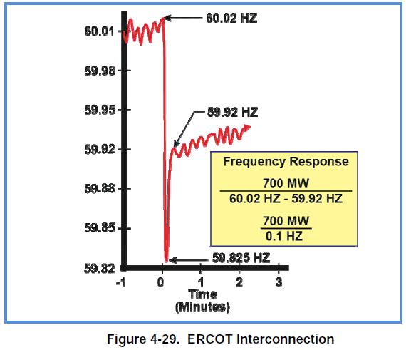
30 Frequency response characteristic (FRC) or Frequency bias factor =D+1/R eq = P L / f (Unit: MW/0.1 Hz) FRC can be developed for any section of a power system. It relates the MW response of the system (or section of the system) to a change in frequency. FRC depends on: The governor droop settings of all on-line units in the system. The condition of the power system when the frequency deviation occurs. The condition of the power system includes current generator output levels, transmission line outages, voltage levels, etc. The frequency response of the connected load in the system. 30


31 FRCs of Different Interconnections 31
32 Limitations of Governor Frequency Control Governors do not recover frequency back to the scheduled value (60Hz) due to the required % droop characteristic. Governor control does not adequately consider the cost of power production so control with governors alone is usually not the most economical alternative. Governor control is intended as a primary means of frequency control. As such governor control is course and not suited to fine adjustment of the interconnected system frequency Other limitations (see Sec. 4.3 in EPRI Tutorial) Spinning Reserve is not considered Governors have dead-bands (not functioning in ~0.04Hz) Depends on the type of Unit (Hydro: very responsive; Combustion turbine: may or may not be responsive; Steam: varies depending on the type) Governors may be blocked: a generator operator can intentionally prevent the unit from responding to a frequency disturbance 32
33 Automatic Generation Control (AGC) Adding supplementary control on load reference set-points of selected generators Controlling prime-mover power to match load variations As system load is continually changing, it is necessary to change the output of generators automatically Primary objective: LFC, i.e. regulating frequency to the specified nominal value, e.g. 60Hz, and maintaining the interchange power between control areas at the scheduled values by adjusting the output of selected generators Secondary objective: Generation dispatch, i.e. distributing the required change in generation among generators to minimize operation costs. AGC is bypassed during large disturbances and emergencies, and other emergency controls are applied. 33
34 AGC for an Isolated Power System An integral controller is added with gain K I Dw() s s(1 + tgs)(1 + tts) = -D P () s s(2 Hs+ D)(1 + t s)(1 + t s) + K + s/ R L g T I Applied to the system in Example 12.1 (Example 12.3) with K I =7 34
35 LFC for a Two-Area System Generators in each area is coherent, i.e. closely coupled internally Two areas are represented by two equivalent generators (modeled by a voltage source behind an equivalent reactance) interconnected by a lossless tie line P = E E sin d XT X X X X T tie 2 dp D P» D d = PD d = P( Dd -Dd ) s 12 s 1 2 dd12 d 12 0 P s dp dd = = cosd 12 d 12 0 E X E T d 12 0 P 12 P 12,max Slope=P s P s is the synchronizing power coefficient P 12, ,0 12
36 LFC with only the Primary Loop Consider a load change P L1 in area 1. Both areas have the same steady-state frequency deviation D w=d w1=dw2 DP -DP -D P =DwD m1 12 L1 1 D P +DP - 0 =DwD m D P12 =DwD2 -DP m 2 The change in mechanical power is determined by the governor speed characteristics -Dw D P m 1 = D P m 2 = R Solve and P R2 -Dw R D P P w = -D 1 1 = -D ( + D ) + ( + D ) b + b R L1 L ( + D ) DP b D P = = (-D ) =0 2 L1 R PL ( + D 1 2 1) + ( + D2) b + b R1 R2 36
37 37
38 AGC with Frequency Bias Tie-Line Control The objective is to restore generation-load balance in each area A simple control strategy: Keep frequency approximately at the nominal value (60Hz) Maintain the tie-line flow at about schedule Each area should absorb its own load changes Area Control Error (ACE): supplementary control signal added to the primary LFC through an integral controller ACE n å = D P + BDw i ij i j= 1 B i : frequency bias factor (may or may not equal i ) Any combination of ACEs containing P ij and will result in steady-state restoration of the tie line flow and frequency deviation (the integral control action reduces each ACE i to 0) What composition of ACE signals should be selected is more important from dynamic performance considerations. 38
39 Comparing different B i s in ACE signals Consider a sudden load increase in Area 1: B i = i =D+1/R i b -DPL ACE =D P + bd w= (-D P ) + b =-DP L1 1 L1 b1+ b2 b1+ b2 b -DP ACE =-D P + b D w=- (-D P ) + b = 0 2 L L1 2 b1+ b2 b1+ b2 Load change is taken care of locally B 1 =k 1, B 2 =k 2 b -D PL kb + b ACE =D P + kbd w= (-D P ) + kb =-DP L1 1 L1 b1+ b2 b1+ b2 b1+ b2 PL ( k 1) ACE P k b -D - b =-D + bd w=- (-D P ) + kb =-DP L1 2 L1 b1+ b2 b1+ b2 b1+ b2 Coefficient of ( 1 = 2 =20) k=2 k=1 k=1/ What does k 1 mean? (k>1: the generator is more active in dynamics) 39
 P m1 P m2 40 P 12")
40 1 ~0 B i = i =D+1/R i 2 ~0 P ref1 P ref2 =0 P m1 >0 P m2 ~0 P 12 ~0 B i =2 i 1 2 In practice, only selected units participate in AGC, i.e. receiving supplementary control signals (ACE) P m1 P m2 40 P 12

41 NERC Balancing Authority A Balancing Authority (BA) is a part of an interconnected power system that is responsible for meeting its own load. Each BA operates an AGC system to balance its generation resources to its load requirements. The generation resources may be internal or purchased from other BAs and transferred over tie-lines between BAs. Similarly, load requirements may include internal customer load, losses, or scheduled sales to other BAs. 41
42 The control center is the headquarters of the BA, where the AGC computer system is typically located. All the data collected by the AGC system is processed in the control center. Based on the gathered data, the AGC signals are transmitted from the control center to the various generators currently involved in supplementary control to tell the generators what generation levels to hold (adjust the generator set-points). It is not necessary for the AGC system to regulate the output of all the generators in a BA. Most BAs have policies which require that as many units as needed are under control and able to respond to the BA s continual load changes. Those units that receive and respond to AGC signals are called regulating units. The number vary from a few for a small BA to 40~50 for the largest BA 42
 is composed of approximately 30 BAs with a distribution similar to the Eastern Interconnection.")
43 NERC Balancing Authorities The EI is composed of approximately 90 BAs, which range in load size from over 130GW peaks to BAs that serve no load but simply use their generation for meeting interchange responsibilities. The WI (WECC) is composed of approximately 30 BAs with a distribution similar to the Eastern Interconnection. The ERCOT and Hydro Quebec are each operated as single BAs. 43
44 AGC for more than two areas By means of ACEs, the frequency bias tie-line control scheme schedules the net import/export for each area, i.e. the algebraic sum of power flows on all the tie lines from that area to the others 44
45 Influences from reserves Sufficient or insufficient spinning reserve Normal conditions: each area has sufficient generation reserve to carry out its supplementary control (AGC) obligations to eliminate the ACE Abnormal conditions: one or more areas cannot fully eliminate the ACE due to insufficient generation reserve; thus, there will be changes in frequency and tie-line flows (under both supplementary control and primary control) Operating reserve resources Spinning reserve: unloaded generating capacity (P ref,max -P ref ), interruptible load (controlled automatically) Non-spinning reserve: not currently connected to the system but can be available within a specific time period, e.g. 15 minutes. Examples are such as combustion turbines while cold standby and some interruptible load. Each BA shall carry enough operating reserves. 45
46 Kundur s Example 11.3 Spinning reserve: 1,000 of 4,000MW B 1 =250MW/0.1Hz Spinning reserve: 1,000 of 10,000MW B 2 =500MW/0.1Hz (losing some spinning reserve) 46
47 Notes on AGC In an interconnect system, all generators with governors may respond to a generation/load change due to either f/r 0 or P ref 0 For load increase or generation loss, only generators with spinning reserves may increase their outputs up to their maximum output limits (by either governors or AGC) (see EPRI tutorial Sec : Spinning reserves consist of unloaded generating capacity that is synchronized to the power system. A governor cannot increase generation in a unit unless that unit is carrying spinning reserves. An AGC system cannot increase a unit s MW output unless that unit is carrying spinning reserves. ) For load decrease, all generators may reduce their outputs as long as higher than their minimum output limits 47
48 Spinning reserve: 1,000 of 4,000MW B 1 =250MW/0.1Hz Spinning reserve: 1,000 of 10,000MW B 2 =500MW/0.1Hz ACE i = B i D f +DP ij =0 with sufficient reserve or 0, otherwise P ref1 P ref2 DPmi -D PLi = DiD f +DPij DP Gi Without supplementary control (AGC): å å å - D PLi, = ( 1/ Ri+ Di) Df i i i = (1/ R+ D) Df 48
49 Spinning reserve: 1,000 of 4,000MW B 1 =250MW/0.1Hz Loss of 1,000MW load 1000 Spinning reserve: 1,000 of 10,000MW B 2 =500MW/0.1Hz Online generators with active governor control 49
50 Spinning reserve: 1,000 of 4,000MW B 1 =250MW/0.1Hz Loss of 1,000MW load Spinning reserve: 1,000 of 10,000MW B 2 =500MW/0.1Hz 50
51 Spinning reserve: 1,000 of 4,000MW B 1 =250MW/0.1Hz Loss of 1,000MW load Spinning reserve: 1,000 of 10,000MW B 2 =500MW/0.1Hz 51
52 Spinning reserve: 1,000 of 4,000MW B 1 =250MW/0.1Hz Loss of 500MW generation carrying part of spinning reserve ? Spinning reserve: 1,000 of 10,000MW B 2 =500MW/0.1Hz (losing some spinning reserve) =333.33MW 52

53 Spinning reserve: 1,000 of 4,000MW B 1 =250MW/0.1Hz Loss of 2,000MW generation, not carrying spinning reserve , Spinning reserve: 1,000 of 10,000MW B 2 =500MW/0.1Hz Only held for the area with sufficient spinning reserve 53
54 Spinning reserve: 1,000 of 4,000MW B 1 =250MW/0.1Hz X Spinning reserve: 1,000 of 10,000MW B 2 =500MW/0.1Hz 54

55 Spinning reserve: 1,000 of 4,000MW B 1 =250MW/0.1Hz X Spinning reserve: 1,000 of 10,000MW B 2 =500MW/0.1Hz 55

56 Frequency response following the loss of a generator 56

57 Impact of Abnormal Frequency Deviations Prolonged operation at frequencies above or below 60Hz can damage power system equipment. Turbine blades of steam turbine generators can be exposed to only a certain amount of off-frequency operation over their entire lifetime. Steam turbine generators often have under- and over-frequency relays installed to trip the unit if operated at off-frequencies for a period A typical steam turbine can be operated, under load, for 10 minutes over the lifetime at 58Hz before damage is likely to occur to the turbine blades 57
58 Frequency Decay Due to Generation Deficiency Severe system disturbances can result in cascading outages and isolation of areas to form electrical islands. If such an islanded area does not have sufficient generation (and spinning reserve), it will experience a frequency decline, which is largely determined by frequency sensitive characteristics of loads. 58
59 Underfrequency Load Shedding In many situations, the frequency decline may lead to tripping of steam turbine generators by underfrequency protective relays, thus aggravating the situation further Underfrequency Load Shedding (UFLS) is a protection program that automatically trips selected customer loads once frequency falls below a specific value. The intent of UFLS is not to recover the frequency to 60 Hz but rather to arrest or stop the frequency decline. Once UFLS has operated, manual intervention by the system operators is likely required to restore the system frequency to a healthy state. 59
60 A typical UFLS setting for a North American utility may include three steps conducted by under-frequency relays, e.g., shedding 10% of the load at 59.3 HZ shedding 10% additional load at 59.0 HZ, and shedding 10% more at 58.7Hz 60


61 UFLS and Automatic Load Restoration in the Western Interconnection Maximum delay Minimum waiting time 61
62 Homework Problems 12.3 and 12.5~12.10 in Saadat s book (3 rd ed., Page 619), due by April 1st (Tue) in class 62
Relationships between Load, Speed Regulation and Frequency. Slope= -R
 elationships between Load, Speed egulation and Frequency Governor Speed characteristic Slope= - Slope=1/D D=2 Frequency-sensitive Load Characteristic Frequency-insensitive Load Characteristic If D (more
Automatic Generation Control. Meth Bandara and Hassan Oukacha
 Automatic Generation Control Meth Bandara and Hassan Oukacha EE194 Advanced Controls Theory February 25, 2013 Outline Introduction System Modeling Single Generator AGC Going Forward Conclusion Introduction
Economic Operation of Power Systems
 Economic Operation of Power Systems Section I: Economic Operation Of Power System Economic Distribution of Loads between the Units of a Plant Generating Limits Economic Sharing of Loads between Different
Load Frequency Control of Multi-Area Power System
 Yurmouk University Al Hijjawi Faculty for Engineering Technology Electrical Power Engineering Department Secondary project: Load Frequency Control of Multi-Area Power System Done by: Hasan Abu Alasal (005975097)
CHAPTER 2 MATHEMATICAL MODELLING OF AN ISOLATED HYBRID POWER SYSTEM FOR LFC AND BPC
 20 CHAPTER 2 MATHEMATICAL MODELLING OF AN ISOLATED HYBRID POWER SYSTEM FOR LFC AND BPC 2.1 INTRODUCTION The technology of the hybrid power system is at an exciting stage of development. Much research effort
ECE 325 Electric Energy System Components 7- Synchronous Machines. Instructor: Kai Sun Fall 2015
 ECE 325 Electric Energy System Components 7- Synchronous Machines Instructor: Kai Sun Fall 2015 1 Content (Materials are from Chapters 16-17) Synchronous Generators Synchronous Motors 2 Synchronous Generators
CHAPTER 2 MODELING OF POWER SYSTEM
 38 CHAPTER 2 MODELING OF POWER SYSTEM 2.1 INTRODUCTION In the day to day scenario, power is an essential commodity to the human beings. The demand is more in developed countries and there is increase in
Frequency-Bias Tie-Line Control of Hydroelectric Generating Stations for Long Distances
 Frequency-Bias Tie-Line Control of Hydroelectric Generating Stations for Long Distances Sukhbir Singh Abstract In this work I have tried to apply effective dedicated online control systems to two equal
UNIT-I Economic Operation of Power Systems -1
 UNIT-I Economic Operation of Power Systems -1 Overview Economic Distribution of Loads between the Units of a Plant Generating Limits Economic Sharing of Loads between Different Plants Automatic Generation
CHAPTER-3 MODELING OF INTERCONNECTED AC-DC POWER SYSTEMS
 35 CHAPER-3 MODELING OF INERCONNECED AC-DC POWER SYSEMS 3. INRODUCION he modeling of power system is essential before entering into the design of Load Frequency Control (LFC). In this chapter, a model
Transient Stability Analysis with PowerWorld Simulator
 Transient Stability Analysis with PowerWorld Simulator T1: Transient Stability Overview, Models and Relationships 2001 South First Street Champaign, Illinois 61820 +1 (217) 384.6330 support@powerworld.com
Chapter 9: Transient Stability
 Chapter 9: Transient Stability 9.1 Introduction The first electric power system was a dc system built by Edison in 1882. The subsequent power systems that were constructed in the late 19 th century were
ECE 585 Power System Stability
 Homework 1, Due on January 29 ECE 585 Power System Stability Consider the power system below. The network frequency is 60 Hz. At the pre-fault steady state (a) the power generated by the machine is 400
ECE 422/522 Power System Operations & Planning/Power Systems Analysis II : 8 - Voltage Stability
 ECE 422/522 Power System Operations & Planning/Power Systems Analysis II : 8 - Voltage Stability Spring 2014 Instructor: Kai Sun 1 Voltage Stability Voltage stability is concerned with the ability of a
Torques 1.0 Two torques We have written the swing equation where speed is in rad/sec as:
 Torques 1.0 Two torques We have written the swing equation where speed is in rad/sec as: 2H Re ( t) T au T mu T eu (1) and when speed is in per-unit as 2H u ( t) Tau Tmu Teu (2) We note that in both cases
QUESTION BANK ENGINEERS ACADEMY. Power Systems Power System Stability 1
 ower ystems ower ystem tability QUETION BANK. A cylindrical rotor generator delivers 0.5 pu power in the steady-state to an infinite bus through a transmission line of reactance 0.5 pu. The generator no-load
Turbines and speed governors
 ELEC0047 - Power system dynamics, control and stability Turbines and speed governors Thierry Van Cutsem t.vancutsem@ulg.ac.be www.montefiore.ulg.ac.be/~vct November 2017 1 / 31 2 / 31 Steam turbines Turbines
Renewable integration and primary control reserve demand in the Indian power system
 Renewable integration and primary control reserve demand in the Indian power system Arun Kannan Division Systems Engineering and Distribution Grids Fraunhofer IWES Kassel, Germany arun.kannan@iwes.fraunhofer.de
Improving the Control System for Pumped Storage Hydro Plant
 011 International Conference on Computer Communication and Management Proc.of CSIT vol.5 (011) (011) IACSIT Press, Singapore Improving the Control System for Pumped Storage Hydro Plant 1 Sa ad. P. Mansoor
A Computer Application for Power System Control Studies
 A Computer Application for Power System Control Studies Dinis C. A. Bucho Student nº55262 of Instituto Superior Técnico Technical University of Lisbon Lisbon, Portugal Abstract - This thesis presents studies
Chapter 2. Planning Criteria. Turaj Amraee. Fall 2012 K.N.Toosi University of Technology
 Chapter 2 Planning Criteria By Turaj Amraee Fall 2012 K.N.Toosi University of Technology Outline 1- Introduction 2- System Adequacy and Security 3- Planning Purposes 4- Planning Standards 5- Reliability
ECE 422/522 Power System Operations & Planning/Power Systems Analysis II : 7 - Transient Stability
 ECE 4/5 Power System Operations & Planning/Power Systems Analysis II : 7 - Transient Stability Spring 014 Instructor: Kai Sun 1 Transient Stability The ability of the power system to maintain synchronism
ECE 522 Power Systems Analysis II 3.3 Voltage Stability
 ECE 522 Power Systems Analysis II 3.3 Voltage Stability Spring 2018 Instructor: Kai Sun 1 Content Basic concepts Voltage collapse, Saddle node bifurcation, P V curve and V Q curve Voltage Stability Analysis
Chapter 3 AUTOMATIC VOLTAGE CONTROL
 Chapter 3 AUTOMATIC VOLTAGE CONTROL . INTRODUCTION TO EXCITATION SYSTEM The basic function of an excitation system is to provide direct current to the field winding of the synchronous generator. The excitation
Analysis of Coupling Dynamics for Power Systems with Iterative Discrete Decision Making Architectures
 Analysis of Coupling Dynamics for Power Systems with Iterative Discrete Decision Making Architectures Zhixin Miao Department of Electrical Engineering, University of South Florida, Tampa FL USA 3362. Email:
LFC of an Interconnected Power System with Thyristor Controlled Phase Shifter in the Tie Line
 International Journal of Computer Applications (975 8887) Volume 41 No.9, March 2 LFC of an Interconnected Power System with Thyristor Controlled Phase Shifter in the Tie Line K. P. Singh Parmar CAMPS,
Transient Stability Analysis of Single Machine Infinite Bus System by Numerical Methods
 International Journal of Electrical and Electronics Research ISSN 348-6988 (online) Vol., Issue 3, pp: (58-66), Month: July - September 04, Available at: www.researchpublish.com Transient Stability Analysis
CHAPTER 3 MATHEMATICAL MODELING OF HYDEL AND STEAM POWER SYSTEMS CONSIDERING GT DYNAMICS
 28 CHAPTER 3 MATHEMATICAL MODELING OF HYDEL AND STEAM POWER SYSTEMS CONSIDERING GT DYNAMICS 3.1 INTRODUCTION This chapter focuses on the mathematical state space modeling of all configurations involved
Comparative Study of Synchronous Machine, Model 1.0 and Model 1.1 in Transient Stability Studies with and without PSS
 Comparative Study of Synchronous Machine, Model 1.0 and Model 1.1 in Transient Stability Studies with and without PSS Abhijit N Morab, Abhishek P Jinde, Jayakrishna Narra, Omkar Kokane Guide: Kiran R Patil
A STATIC AND DYNAMIC TECHNIQUE CONTINGENCY RANKING ANALYSIS IN VOLTAGE STABILITY ASSESSMENT
 A STATIC AND DYNAMIC TECHNIQUE CONTINGENCY RANKING ANALYSIS IN VOLTAGE STABILITY ASSESSMENT Muhammad Nizam Engineering Faculty Sebelas Maret University (Ph.D Student of Electrical, Electronic and System
POWER SYSTEM STABILITY AND CONTROL
 POWER SYSTEM STABILITY AND CONTROL P. KUNDUR Vice-President, Power Engineering Powertech Labs Inc., Surrey, British Columbia Formerly Manager Analytical Methods and Specialized Studies Department Power
Generators. What its all about
 Generators What its all about How do we make a generator? Synchronous Operation Rotor Magnetic Field Stator Magnetic Field Forces and Magnetic Fields Force Between Fields Motoring Generators & motors are
LOAD FREQUENCY CONTROL IN A SINGLE AREA POWER SYSTEM
 LOAD FREQUENCY CONTROL IN A SINGLE AREA POWER SYSTEM PRANAB PATNAIK (109EE0294) Department of Electrical Engineering National Institute of Technology Rourkela LOAD FREQUENCY CONTROL IN A SINGLE AREA POWER
Load Frequency Control in Shipboard Power Systems: Design and Simulation. A Thesis. Submitted to the Faculty. Drexel University.
 Load Frequency Control in Shipboard Power Systems: Design and Simulation A Thesis Submitted to the Faculty of Drexel University by Uthara Mary Reji in partial fulfillment of the requirements for the degree
1. Introduction. Keywords Transient Stability Analysis, Power System, Swing Equation, Three-Phase Fault, Fault Clearing Time
 Energy and Power 17, 7(1): -36 DOI: 1.593/j.ep.1771.3 Numerical Simulations for Transient Stability Analysis of Two-Machine Power System Considering Three-Phase Fault under Different Fault Clearing Times
Power System Stability GENERATOR CONTROL AND PROTECTION
 Power System Stability Outline Basis for Steady-State Stability Transient Stability Effect of Excitation System on Stability Small Signal Stability Power System Stabilizers Speed Based Integral of Accelerating
POWER SYSTEM STABILITY
 LESSON SUMMARY-1:- POWER SYSTEM STABILITY 1. Introduction 2. Classification of Power System Stability 3. Dynamic Equation of Synchronous Machine Power system stability involves the study of the dynamics
EE2351 POWER SYSTEM OPERATION AND CONTROL UNIT I THE POWER SYSTEM AN OVERVIEW AND MODELLING PART A
 EE2351 POWER SYSTEM OPERATION AND CONTROL UNIT I THE POWER SYSTEM AN OVERVIEW AND MODELLING PART A 1. What are the advantages of an inter connected system? The advantages of an inter-connected system are
Performance Improvement of Hydro-Thermal System with Superconducting Magnetic Energy Storage
 Volume 114 No. 10 2017, 397-405 ISSN: 1311-8080 (printed version); ISSN: 1314-3395 (on-line version) url: http://www.ijpam.eu ijpam.eu Performance Improvement of Hydro-Thermal System with Superconducting
Adaptive under frequency load shedding using synchrophasor measurement
 Adaptive under load shedding using synchrophasor measurement Abstract - The imbalance between the generation and the demand is the major factor that causes instability in a power system. Conventional Under
Equivalent Circuits with Multiple Damper Windings (e.g. Round rotor Machines)
") Equivalent Circuits with Multiple Damper Windings (e.g. Round rotor Machines) d axis: L fd L F - M R fd F L 1d L D - M R 1d D R fd R F e fd e F R 1d R D Subscript Notations: ( ) fd ~ field winding quantities
Equivalent Circuits with Multiple Damper Windings (e.g. Round rotor Machines) d axis: L fd L F - M R fd F L 1d L D - M R 1d D R fd R F e fd e F R 1d R D Subscript Notations: ( ) fd ~ field winding quantities
DYNAMIC RESPONSE OF A GROUP OF SYNCHRONOUS GENERATORS FOLLOWING DISTURBANCES IN DISTRIBUTION GRID
 Engineering Review Vol. 36 Issue 2 8-86 206. 8 DYNAMIC RESPONSE OF A GROUP OF SYNCHRONOUS GENERATORS FOLLOWING DISTURBANCES IN DISTRIBUTION GRID Samir Avdaković * Alija Jusić 2 BiH Electrical Utility Company
LOAD FREQUENCY CONTROL WITH THERMAL AND NUCLEAR INTERCONNECTED POWER SYSTEM USING PID CONTROLLER
 LOAD FREQUENCY CONTROL WITH THERMAL AND NUCLEAR INTERCONNECTED POWER SYSTEM USING PID CONTROLLER Amitesh Kumar, Prof. SulataBhandari, Dr. RintuKhanna 3,,3 Pec University of Technology, Chandigarh,( India)
Micro-grid to System Synchronization Based on Pre-Insertion Impedance Method (Version 1.0) By Peter Zhou University of Alberta Jan 30 th, 2015
 By Peter Zhou University of Alberta Jan 30 th, 2015") Micro-grid to System Synchronization Based on Pre-Insertion Impedance Method (Version 1.0) By Peter Zhou University of Alberta Jan 30 th, 2015 Outline 1. What is Synchronization? 2. Synchronization Concerns?
Micro-grid to System Synchronization Based on Pre-Insertion Impedance Method (Version 1.0) By Peter Zhou University of Alberta Jan 30 th, 2015 Outline 1. What is Synchronization? 2. Synchronization Concerns?
Contents. PART I METHODS AND CONCEPTS 2. Transfer Function Approach Frequency Domain Representations... 42
 Contents Preface.............................................. xiii 1. Introduction......................................... 1 1.1 Continuous and Discrete Control Systems................. 4 1.2 Open-Loop
SMALL SIGNAL ANALYSIS OF LOAD ANGLE GOVERNING AND EXCITATION CONTROL OF AC GENERATORS
 Nigerian Journal of Technology, Vol. 24, No. 2, September 2005 Obe 1 SMALL SIGNAL ANALYSIS OF LOAD ANGLE GOVERNING AND EXCITATION CONTROL OF AC GENERATORS E. S. OBE, AMIEE Department of Electrical Engineering,
Modelling of Primary Frequency Control and Effect Analyses of Governing System Parameters on the Grid Frequency. Zhixin Sun
 Modelling of Primary Frequency Control and Effect Analyses of Governing System Parameters on the Grid Frequency Zhixin Sun Outline Introduction Mathematical Model of Primary Frequency Control Dynamic Test
Steam-Hydraulic Turbines Load Frequency Controller Based on Fuzzy Logic Control
 esearch Journal of Applied Sciences, Engineering and echnology 4(5): 375-38, ISSN: 4-7467 Maxwell Scientific Organization, Submitted: February, Accepted: March 6, Published: August, Steam-Hydraulic urbines
CHAPTER 1 Basic Concepts of Control System. CHAPTER 6 Hydraulic Control System
 CHAPTER 1 Basic Concepts of Control System 1. What is open loop control systems and closed loop control systems? Compare open loop control system with closed loop control system. Write down major advantages
You know for EE 303 that electrical speed for a generator equals the mechanical speed times the number of poles, per eq. (1).
.") Stability 1 1. Introduction We now begin Chapter 14.1 in your text. Our previous work in this course has focused on analysis of currents during faulted conditions in order to design protective systems
Stability 1 1. Introduction We now begin Chapter 14.1 in your text. Our previous work in this course has focused on analysis of currents during faulted conditions in order to design protective systems
Monitoring and Control of Electric Power Systems
 Monitoring and Control of Electric Power Systems Peter W. Sauer University of Illinois at Urbana-Champaign October 21, 2016 CREDC all-hands meeting Control centers Traditional Power System Operating States
EE 451 Power System Stability
 EE 451 Power System Stability Power system operates in synchronous mode Power system is subjected to a wide range of disturbances (small and large) - Loads and generation changes - Network changes - Faults
Power System Stability and Control. Dr. B. Kalyan Kumar, Department of Electrical Engineering, Indian Institute of Technology Madras, Chennai, India
 Power System Stability and Control Dr. B. Kalyan Kumar, Department of Electrical Engineering, Indian Institute of Technology Madras, Chennai, India Contents Chapter 1 Introduction to Power System Stability
Dynamic simulation of a five-bus system
 ELEC0047 - Power system dynamics, control and stability Dynamic simulation of a five-bus system Thierry Van Cutsem t.vancutsem@ulg.ac.be www.montefiore.ulg.ac.be/~vct November 2017 1 / 16 System modelling
ECEN 667 Power System Stability Lecture 20: Oscillations, Small Signal Stability Analysis
 ECEN 667 Power System Stability Lecture 20: Oscillations, Small Signal Stability Analysis Prof. Tom Overbye Dept. of Electrical and Computer Engineering Texas A&M University, overbye@tamu.edu 1 Announcements
(b) A unity feedback system is characterized by the transfer function. Design a suitable compensator to meet the following specifications:
 A unity feedback system is characterized by the transfer function. Design a suitable compensator to meet the following specifications:") 1. (a) The open loop transfer function of a unity feedback control system is given by G(S) = K/S(1+0.1S)(1+S) (i) Determine the value of K so that the resonance peak M r of the system is equal to 1.4.
1. (a) The open loop transfer function of a unity feedback control system is given by G(S) = K/S(1+0.1S)(1+S) (i) Determine the value of K so that the resonance peak M r of the system is equal to 1.4.
Sensitivity Analysis of Load-Damping Characteristic in Power System Frequency Regulation
 1324 IEEE TRANSACTIONS ON POWER SYSTEMS, VOL. 28, NO. 2, MAY 2013 Sensitivity Analysis of Load-Damping Characteristic in Power System Frequency Regulation Hao Huang, Student Member, IEEE, and Fangxing
Generalized Injection Shift Factors and Application to Estimation of Power Flow Transients
 Generalized Injection Shift Factors and Application to Estimation of Power Flow Transients Yu Christine Chen, Alejandro D. Domínguez-García, and Peter W. Sauer Department of Electrical and Computer Engineering
Cascading Outages in Power Systems. Rui Yao
 Cascading Outages in Power Systems Rui Yao yaorui.thu@gmail.com Outline Understanding cascading outages Characteristics of cascading outages Mitigation of cascading outages Understanding cascading outages
Transient Stability Assessment of Synchronous Generator in Power System with High-Penetration Photovoltaics (Part 2)
") Journal of Mechanics Engineering and Automation 5 (2015) 401-406 doi: 10.17265/2159-5275/2015.07.003 D DAVID PUBLISHING Transient Stability Assessment of Synchronous Generator in Power System with High-Penetration
Journal of Mechanics Engineering and Automation 5 (2015) 401-406 doi: 10.17265/2159-5275/2015.07.003 D DAVID PUBLISHING Transient Stability Assessment of Synchronous Generator in Power System with High-Penetration
Cyber-Attacks in the Automatic Generation Control
 Cyber-Attacks in the Automatic Generation Control Maria Vrakopoulou, Peyman Mohajerin Esfahani, Kostas Margellos, John Lygeros and Göran Andersson Abstract Power systems are traditionally monitored and
11.1 Power System Stability Overview
 11.1 Power System Stability Overview This introductory section provides a general description of the power system stability phenomena including fundamental concepts, classification, and definition of associated
Effects of Various Uncertainty Sources on Automatic Generation Control Systems
 Effects of Various Uncertainty Sources on Automatic Generation Control Systems D. Apostolopoulou, Y. C. Chen, J. Zhang, A. D. Domínguez-García, and P. W. Sauer University of Illinois at Urbana-Champaign
1 Unified Power Flow Controller (UPFC)
") Power flow control with UPFC Rusejla Sadikovic Internal report 1 Unified Power Flow Controller (UPFC) The UPFC can provide simultaneous control of all basic power system parameters ( transmission voltage,
Power flow control with UPFC Rusejla Sadikovic Internal report 1 Unified Power Flow Controller (UPFC) The UPFC can provide simultaneous control of all basic power system parameters ( transmission voltage,
Contents Economic dispatch of thermal units
 Contents 2 Economic dispatch of thermal units 2 2.1 Introduction................................... 2 2.2 Economic dispatch problem (neglecting transmission losses)......... 3 2.2.1 Fuel cost characteristics........................
QFT Framework for Robust Tuning of Power System Stabilizers
 45-E-PSS-75 QFT Framework for Robust Tuning of Power System Stabilizers Seyyed Mohammad Mahdi Alavi, Roozbeh Izadi-Zamanabadi Department of Control Engineering, Aalborg University, Denmark Correspondence
Accurate and Estimation Methods for Frequency Response Calculations of Hydroelectric Power Plant
 Accurate and Estimation Methods for Frequency Response Calculations of Hydroelectric Poer Plant SHAHRAM JAI, ABOLFAZL SALAMI epartment of Electrical Engineering Iran University of Science and Technology
Frequency and Damping Characteristics of Generators in Power Systems
 Frequency and Damping Characteristics of Generators in Power Systems Xiaolan Zou Thesis submitted to the Faculty of the Virginia Polytechnic Institute and State University in partial fulfillment of the
Automatic Generation Control of interconnected Hydro Thermal system by using APSO scheme
 IOSR Journal of Electrical and Electronics Engineering (IOSR-JEEE) e-issn: 2278-1676,p-ISSN: 2320-3331 PP 50-57 www.iosrjournals.org Automatic Generation Control of interconnected Hydro Thermal system
Study of Sampled Data Analysis of Dynamic Responses of an Interconnected Hydro Thermal System
 IJECT Vo l. 4, Is s u e Sp l - 1, Ja n - Ma r c h 2013 ISSN : 2230-7109 (Online) ISSN : 2230-9543 (Print) Study of Sampled Data Analysis of Dynamic Responses of an Interconnected Hydro Thermal System 1
International Workshop on Wind Energy Development Cairo, Egypt. ERCOT Wind Experience
 International Workshop on Wind Energy Development Cairo, Egypt ERCOT Wind Experience March 22, 21 Joel Mickey Direcr of Grid Operations Electric Reliability Council of Texas jmickey@ercot.com ERCOT 2 2
A New Improved Method to Damp Inter-Area Oscillations in. Power Systems with SSR Mitigation and Zone Protection. Compensation
 A New Improved Method to Damp Inter-Area Oscillations in Power Systems with SSR Mitigation and Zone Protection Compensation Thesis submitted for the degree of Doctor of Philosophy at the University of
Virtual Inertia: Current Trends and Future Directions
 applied sciences Review Virtual Inertia: Current Trends and Future Directions Ujjwol Tamrakar 1, Dipesh Shrestha 1, Manisha Maharjan 1, Bishnu P. Bhattarai 2, Timothy M. Hansen 1 and Reinaldo Tonkoski
Applications of superconducting magnetic energy storage in electrical power systems
 Bull. Mater. Sci., Vol. 14, No. 4. August 1991. pp. 1135-1140. Ct_~ Printed in ndia. Applications of superconducting magnetic energy storage in electrical power systems S BANERJEE and T N SAHA Department
Reliability of Bulk Power Systems (cont d)
") Reliability of Bulk Power Systems (cont d) Important requirements of a reliable electric power service Voltage and frequency must be held within close tolerances Synchronous generators must be kept running
Reliability of Bulk Power Systems (cont d) Important requirements of a reliable electric power service Voltage and frequency must be held within close tolerances Synchronous generators must be kept running
Module 6 : Preventive, Emergency and Restorative Control. Lecture 27 : Normal and Alert State in a Power System. Objectives
 Module 6 : Preventive, Emergency and Restorative Control Lecture 27 : Normal and Alert State in a Power System Objectives In this lecture you will learn the following Different states in a power system
Dynamics of the synchronous machine
 ELEC0047 - Power system dynamics, control and stability Dynamics of the synchronous machine Thierry Van Cutsem t.vancutsem@ulg.ac.be www.montefiore.ulg.ac.be/~vct October 2018 1 / 38 Time constants and
Predicting, controlling and damping inter-area mode oscillations in Power Systems including Wind Parks
 3rd IASME/WSEAS Int. Conf. on Energy & Environment, University of Cambridge, UK, February 3-5, 008 Predicting, controlling and damping inter-area mode oscillations in Power Systems including Wind Parks
Small Signal Stability Analysis of Power System with Increased Penetration of PV Generation
 Kalpa Publications in Engineering Volume, 207, Pages 200 207 ICRISET207. International Conference on Research and Innovations in Science, Engineering &Technology. Selected Papers in Engineering Small Signal
Delay-Robust Distributed Secondary Frequency Control: A Case Study
 Delay-Robust Distributed Secondary Frequency Control: A Case Study Sultan Alghamdi, Nathan Smith, Petros Aristidou School of Electronic and Electrical Engineering University of Leeds, Leeds, UK {elsalg,
ECE 476. Exam #2. Tuesday, November 15, Minutes
 Name: Answers ECE 476 Exam #2 Tuesday, November 15, 2016 75 Minutes Closed book, closed notes One new note sheet allowed, one old note sheet allowed 1. / 20 2. / 20 3. / 20 4. / 20 5. / 20 Total / 100
Deterministic Sizing of the Frequency Bias Factor of Secondary Control
 power systems eehlaboratory Andreas Ritter Deterministic Sizing of the Frequency Bias Factor of Secondary Control Semester Thesis PSL1106 EEH Power Systems Laboratory Swiss Federal Institute of Technology
Power System Analysis Prof. A. K. Sinha Department of Electrical Engineering Indian Institute of Technology, Kharagpur
 Power System Analysis Prof. A. K. Sinha Department of Electrical Engineering Indian Institute of Technology, Kharagpur Lecture - 9 Transmission Line Steady State Operation Welcome to lesson 9, in Power
Index. Index. More information. in this web service Cambridge University Press
 A-type elements, 4 7, 18, 31, 168, 198, 202, 219, 220, 222, 225 A-type variables. See Across variable ac current, 172, 251 ac induction motor, 251 Acceleration rotational, 30 translational, 16 Accumulator,
Toward Standards for Model-Based Control of Dynamic Interactions in Large Electric Power Grids
 Toward Standards for Model-Based Control of Dynamic Interactions in Large Electric Power Grids Marija D. Ilić andqixingliu Carnegie Mellon University, Pittsburgh, USA E-mail: milic@ece.cmu.edu Tel/Fax:
Pursuant to Section 205 of the Federal Power Act ( FPA ) 1 and the Commission s
 1 and the Commission s") PJM Interconnection 2750 Monroe Boulevard Norristown, PA 19403-2497 Steven R. Pincus Associate General Counsel 610.666.4370 fax 610.666.8211 steven.pincus@pjm.com July 31, 2017 Honorable Kimberly D. Bose
PJM Interconnection 2750 Monroe Boulevard Norristown, PA 19403-2497 Steven R. Pincus Associate General Counsel 610.666.4370 fax 610.666.8211 steven.pincus@pjm.com July 31, 2017 Honorable Kimberly D. Bose
Stability Effects of Frequency Controllers and Transmission Line Configurations on Power Systems with Integration of Wind Power
 Stability Effects of Frequency Controllers and Transmission Line Configurations on Power Systems with Integration of Wind Power by Hussein Mohamed Abdelhalim B.S. Electrical Engineering University of Florida,
Implementing Consensus Based Distributed Control in Power System Toolbox
 Implementing Consensus Based Distributed Control in Power System Toolbox Minyue Ma and Lingling Fan Department of Electrical Engineering University of South Florida Tampa, FL 6 url: http://power.eng.usf.edu
Real-Life Observations of Power System Dynamic Phenomena Some Interesting Aspects
 Real-Life Observations of Power System Dynamic Phenomena Some Interesting Aspects A.M.Kulkarni Department of Electrical Engineering, IIT Bombay and Visiting Professor, University of Manitoba The Indian
THE UNIVERSITY OF NEW SOUTH WALES. School of Electrical Engineering & Telecommunications FINALEXAMINATION. Session
 Name: Student ID: Signature: THE UNIVERSITY OF NEW SOUTH WALES School of Electrical Engineering & Telecommunications FINALEXAMINATION Session 00 ELEC46 Power System Analysis TIME ALLOWED: 3 hours TOTAL
B.E. / B.Tech. Degree Examination, April / May 2010 Sixth Semester. Electrical and Electronics Engineering. EE 1352 Power System Analysis
 B.E. / B.Tech. Degree Examination, April / May 2010 Sixth Semester Electrical and Electronics Engineering EE 1352 Power System Analysis (Regulation 2008) Time: Three hours Answer all questions Part A (10
IMPACT OF DYNAMIC DEMAND RESPONSE IN THE LOAD FREQUENCY CONTROL P CHANDRASEKHARA 1, B PARASURAM 2, C VISWANATH 3, A SURESHBABU 4
 IMPACT OF DYNAMIC DEMAND RESPONSE IN THE LOAD FREQUENCY CONTROL P CHANDRASEKHARA 1, B PARASURAM 2, C VISWANATH 3, A SURESHBABU 4 1 PG Scholar, Dept. of EEE, B.I.T Institute of Technology,Hindupur Affiliated
INSTITUTE OF AERONAUTICAL ENGINEERING (Autonomous)
") INSTITUTE OF AERONAUTICAL ENGINEERING (Autonomous) Dundigal, Hyderabad - 500 043 ELECTRICAL AND ELECTRONICS ENGINEERING QUESTION BANK Course Name : Computer Methods in Power Systems Course Code : A60222
INSTITUTE OF AERONAUTICAL ENGINEERING (Autonomous) Dundigal, Hyderabad - 500 043 ELECTRICAL AND ELECTRONICS ENGINEERING QUESTION BANK Course Name : Computer Methods in Power Systems Course Code : A60222
EE 742 Chapter 3: Power System in the Steady State. Y. Baghzouz
 EE 742 Chapter 3: Power System in the Steady State Y. Baghzouz Transmission Line Model Distributed Parameter Model: Terminal Voltage/Current Relations: Characteristic impedance: Propagation constant: π
Joint Frequency Regulation and Economic Dispatch Using Limited Communication
 Joint Frequency Regulation and Economic Dispatch Using Limited Communication Jianan Zhang, and Eytan Modiano Massachusetts Institute of Technology, Cambridge, MA, USA Abstract We study the performance
Behaviour of synchronous machine during a short-circuit (a simple example of electromagnetic transients)
") ELEC0047 - Power system dynamics, control and stability (a simple example of electromagnetic transients) Thierry Van Cutsem t.vancutsem@ulg.ac.be www.montefiore.ulg.ac.be/~vct October 2018 1 / 25 Objectives
ELEC0047 - Power system dynamics, control and stability (a simple example of electromagnetic transients) Thierry Van Cutsem t.vancutsem@ulg.ac.be www.montefiore.ulg.ac.be/~vct October 2018 1 / 25 Objectives
California Independent System Operator (CAISO) Challenges and Solutions
 Challenges and Solutions") California Independent System Operator (CAISO) Challenges and Solutions Presented by Brian Cummins Manager, Energy Management Systems - CAISO California ISO by the numbers 65,225 MW of power plant capacity
California Independent System Operator (CAISO) Challenges and Solutions Presented by Brian Cummins Manager, Energy Management Systems - CAISO California ISO by the numbers 65,225 MW of power plant capacity
EVALUATION OF THE IMPACT OF POWER SECTOR REFORM ON THE NIGERIA POWER SYSTEM TRANSIENT STABILITY
 EVALUATION OF THE IMPACT OF POWER SECTOR REFORM ON THE NIGERIA POWER SYSTEM TRANSIENT STABILITY F. I. Izuegbunam * Department of Electrical & Electronic Engineering, Federal University of Technology, Imo
Alireza Mousavi Brunel University
 Alireza Mousavi Brunel University 1 » Control Process» Control Systems Design & Analysis 2 Open-Loop Control: Is normally a simple switch on and switch off process, for example a light in a room is switched
Renewables and the Smart Grid. Trip Doggett President & CEO Electric Reliability Council of Texas
 Renewables and the Smart Grid Trip Doggett President & CEO Electric Reliability Council of Texas North American Interconnected Grids The ERCOT Region is one of 3 North American grid interconnections. The