Pinched hysteresis loops are a fingerprint of square law capacitors
|
|
|
- Lindsay McBride
- 5 years ago
- Views:
Transcription
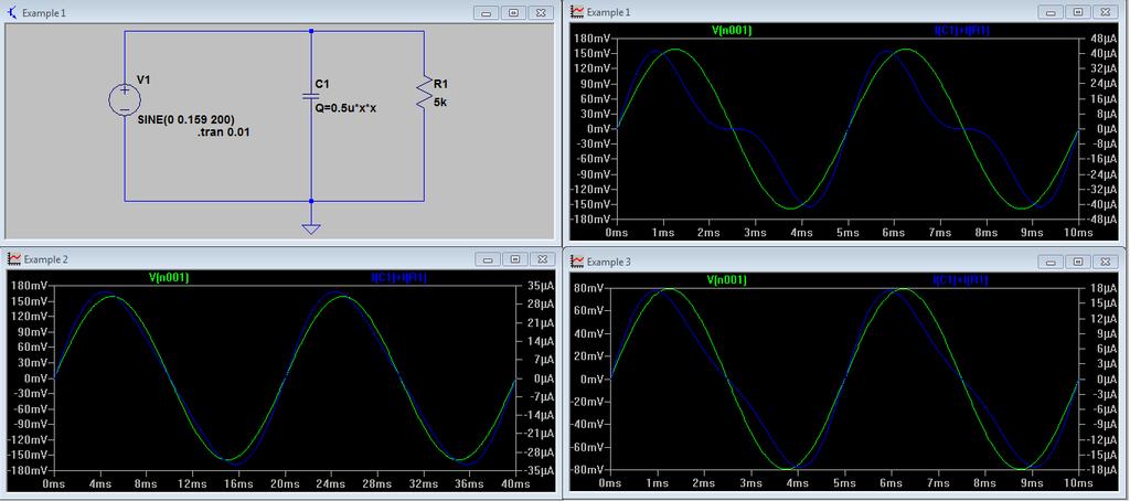
1 Pinched hysteresis loops are a fingerprint of square law capacitors Blaise Mouttet Abstract It has been claimed that pinched hysteresis curves are the fingerprint of memristors. This paper demonstrates that a linear resistor in parallel with a nonlinear, square law capacitor also produces pinched hysteresis curves. Spice simulations are performed examining the current vs. voltage behavior of this circuitry under different amplitudes and frequencies of an input signal. Based on this finding a more generalized dynamic systems model is suggested for ReRAM and neuromorphic modeling to cover a broader range of pinched hysteresis curves. Keywords- non-linear circuit theory, RRAM, ReRAM, memristor, memristive systems, memadmittance systems, memresistor I. INTRODUCTION It has been argued that the memristor should be considered a fundamental non-linear circuit element based on the inability to replicate memristor properties by a combination of resistors, capacitors, and inductors [1-2]. More recently it was suggested that pinched hysteresis is a defining property of memristors [3]. Others have claimed pinched hysteresis of TiO 2 thin films as sufficient proof for the discovery of a memristor [4] and have used the pinched hysteresis definition to suggest that ReRAM, phase change memory, and MRAM should also be considered memristors [5]. Several examples of dynamic systems capable of producing pinched hysteresis curves and yet falling outside of the definition of the memristor or memristive systems have also been shown [6-8]. It has been argued that some of these examples include pinched hysteresis loops sensitive to initial condition, amplitude, and frequency variations [9]. As explained in [10] this argument supports the position that the memristor and memristive systems represent incomplete models for ReRAM since the pinched hysteresis of TiO 2 thin film resistance switches have been shown to be sensitive to initial conditions (e.g., Fig. 1a of [11]). Other dynamic systems models for ReRAM have also been considered [12]. This paper demonstrates that a pinched hysteresis effect can be generated using a linear resistor and a nonlinear capacitor. Based on this finding a more generalized dynamic systems model is suggested for ReRAM and neuromorphic modeling of memory resistors. II. SQUARE LAW CAPACITOR MODEL An ideal linear capacitor is defined based upon a proportional relationship between electric charge q c and an applied voltage v. A square law (nonlinear) capacitor is proposed based upon a proportional relationship between electric charge q c and the square of an applied voltage v such that where C v is a proportionality constant having units of farads/volt. Differentiating (1) produces a relationship between the capacitive current (i c = dq c /dt) and voltage v. Based on Kirchoff s current law placing a square law capacitor in parallel with a linear resistor produces a total current i T equal to the sum of the resistor current i R and the capacitive current i C.
 can then be factored out producing ( ) Substituting a sinusoidal applied voltage with amplitude V m and frequency f (i.e. v(t) = V m sin( ft)) into (5) produces ( ) It is noted that based on (5) v(t)=0 implies i T (t)=0.")
 is -1 the signal voltage has an upper bound.")
2 This equation can be expressed in terms of voltage using (2) combined with Ohm s law with R equal to the resistance. The voltage term v(t) can then be factored out producing ( ) Substituting a sinusoidal applied voltage with amplitude V m and frequency f (i.e. v(t) = V m sin( ft)) into (5) produces ( ) It is noted that based on (5) v(t)=0 implies i T (t)=0. It is also noted that based on (6) for the voltage and the current to be the same sign (positive or negative) the following inequality must hold. Since the minimum value of cos( t) is -1 the signal voltage has an upper bound. The signal amplitude V m was selected to be the maximum value of equation (8) so that the sign of the current is always the same as the sign of the voltage. Example 2 (R=5k, C v =0.5 F/V, f=50hz, V m =0.159V) The following section provides results of a circuit simulation of the above described square law capacitor in parallel with a linear resistor. III. CIRCUIT SIMULATION The following examples were simulated using LTSpice IV based on a linear resistor in parallel with a square law capacitor (see page 5). Lissajous curves were modeled using an online parametric graphing tool [13] based on equation (6). Example 1 (R=5k, C v =0.5 F/V, f=200hz, V m =0.159V) For the values of this example equation (6) reduces to In this example the frequency was reduced to 25% of that in Example 1. The hysteresis curve begins to degenerate as the frequency is reduced and, as

3 evident from (6), at zero frequency the circuit becomes purely resistive. This behavior may be useful to distinguish a square law capacitor from the theoretical memristor in which decreasing the frequency would increase the hysteresis effect. Example 3 (R=5k, C v =0.5 F/V, f=200hz, V m =0.0795V) where i R (v(t)) is a continuous function of voltage v(t) representing the resistive current and C(v(t)) is a continuous function of voltage v(t) representing the capacitance. The zero-crossing property will be preserved provided that i R (0)=0 and C(0)=0. In order to model ReRAM and other electronic devices exhibiting memory effects, equation (12) needs to be further generalized as a memadmittance system [14]. This may be achieved by including a dependence on state variables for the resistive current and capacitive functions in which the state variables are defined by differential equations. A state-space representation of this generalization is given as In this example the voltage amplitude is reduced to half of that in Example 1. The hysteresis curve begins to degenerate as the amplitude is reduced similarly to the behavior of the theoretical memristor. IV. GENERALIZED MEMADMITTANCE SYSTEMS The theoretical concept of an ideal square law capacitor may be difficult (perhaps impossible) to recreate in real physical systems. It might be possible to construct a device that oscillates between positive and negative capacitance having a zero capacitance at zero voltage. But even if this is possible a more general model than square law capacitance is likely to be necessary to capture the dynamics of such systems. A generalized non-linear version of (4) is proposed as In this case x(t) is a state variable (or state vector if the state is defined by multiple variables) and i R, C, and f represent continuous functions. In order to preserve zero-crossing behavior the following constraints may be required. It is notable that it may be useful for ReRAM modeling to loosen the constraints of (15) and (16) under some cases by assuming equality with zero only under a limited range of the state variable. For example, in some forms of ReRAM such as TiO 2 resistance switching the zero-crossing behavior is not observed in the initial state prior to a formation step (see Fig. 1a of [11]). V. CONCLUSION This paper has shown that it is possible to construct a pinched hysteresis loop using a linear resistor and a non-linear capacitor. It is possible that at least some observations of pinched hysteresis
4 Lissajous curves may be indicative of square law capacitance or oscillation between positive and negative capacitance rather than a memristive effect. In cases where a memory effect is involved a more generic dynamic systems model has been proposed. REFERENCES [1] L.O.Chua, Memristor-the missing circuit element, IEEE Trans. Circuit Theory, vol. 18, pp , Sept [2] L.O. Chua, S.M. Kang, "Memristive devices and systems," Proceedings of the IEEE, vol. 64, no. 2, Feb [3] L.O. Chua, Resistance switching memories are memristors, Applied Physics A, vol 102, no. 4, Jan [4] D.B. Strukov, G.S. Snider, D.R. Stewart, R.S. Williams, The missing memristor found, Nature, vol.453, May [5] R.S.Williams, A short history of memristor development, Dec. 22, 2011 (last visited April 30, 2012). [6] B. Mouttet, Memresistors and non-memristive zero crossing hysteresis curves, arxiv: v5, Feb [7] P. Clarke, Memristor brouhaha bubbles under, EETimes, Jan. 16, 2012 (last visited April 30, 2012). [8] P. Marks, Big bucks hang on who joins memristor club, New Scientist, vol. 213, no 2853, Feb 25, [9] H. Kim, MP Sah, SP Adhikari, Pinched Hysteresis Loops is the Fingerprint of Memristive Devices, arxiv: v2, Feb [10] B. Mouttet, Response to Pinched Hysteresis Loops is the Fingerprint of Memristive Devices, Feb. 23, 2012 (last visited April 30, 2012). [11] F.Argall, Switching phenomena in titanium oxide thin films, Solid- State Electronics, Vol. 11, pp , [12] B.Mouttet, Dynamic Systems Model for Ionic Mem-Resistors based on Harmonic Oscillation, arxiv:1103:2190v4, Jun [13] (last visited April 30, 2012). [14] B.Mouttet, A memadmittance systems model for thin film memory materials, arxiv:1003:2842, Mar
5
A short history of memristor development. R. Stanley Williams HP Labs
 A short history of memristor development R. Stanley Williams HP Labs Historical Background During the 1960's, Prof. Leon Chua, who was then at Purdue University, established the mathematical foundation
Window Function Analysis of Nonlinear Behaviour of Fourth Fundamental Passive Circuit Element: Memristor
 IOSR Journal of Electronics and Communication Engineering (IOSR-JECE) e-issn: 2278-2834,p- ISSN: 2278-8735.Volume 12, Issue 3, Ver. III (May - June 217), PP 58-63 www.iosrjournals.org Window Function Analysis
Implementing Memristor Based Chaotic Circuits
 Implementing Memristor Based Chaotic Circuits Bharathwaj Muthuswamy Electrical Engineering and Computer Sciences University of California at Berkeley Technical Report No. UCB/EECS-2009-156 http://www.eecs.berkeley.edu/pubs/techrpts/2009/eecs-2009-156.html
A Memristor Model with Piecewise Window Function
 RAIOENGINEERING, VOL. 22, NO. 4, ECEMBER 23 969 A Memristor Model with Piecewise Window Function Juntang YU, Xiaomu MU, Xiangming XI, Shuning WANG ept. of Automation, TNList, Tsinghua University, Qinghuayuan,
Lecture 39. PHYC 161 Fall 2016
 Lecture 39 PHYC 161 Fall 016 Announcements DO THE ONLINE COURSE EVALUATIONS - response so far is < 8 % Magnetic field energy A resistor is a device in which energy is irrecoverably dissipated. By contrast,
Physics for Scientists & Engineers 2
 Electromagnetic Oscillations Physics for Scientists & Engineers Spring Semester 005 Lecture 8! We have been working with circuits that have a constant current a current that increases to a constant current
Mathematical analysis of a third-order memristor-based Chua oscillators
 Mathematical analysis of a third-order memristor-based Chua oscillators Vanessa Botta, Cristiane Néspoli, Marcelo Messias Depto de Matemática, Estatística e Computação, Faculdade de Ciências e Tecnologia,
CIRCUITS elements that store information without the
 1 Circuit elements with memory: memristors, memcapacitors and meminductors Massimiliano Di Ventra, Yuriy V. Pershin, and Leon O. Chua, Fellow, IEEE arxiv:91.3682v1 [cond-mat.mes-hall] 23 Jan 29 Abstract
Finding the Missing Memristor
 February 11, 29 Finding the Missing Memristor 3 nm Stan Williams HP 26 Hewlett-Packard Development Company, L.P. The information contained herein is subject to change without notice Acknowledgments People
From Spin Torque Random Access Memory to Spintronic Memristor. Xiaobin Wang Seagate Technology
 From Spin Torque Random Access Memory to Spintronic Memristor Xiaobin Wang Seagate Technology Contents Spin Torque Random Access Memory: dynamics characterization, device scale down challenges and opportunities
Chaotic memristor. T. Driscoll Y.V. Pershin D.N. Basov M. Di Ventra
 Appl Phys A (2011) 102: 885 889 DOI 10.1007/s00339-011-6318-z Chaotic memristor T. Driscoll Y.V. Pershin D.N. Basov M. Di Ventra Received: 18 October 2010 / Accepted: 22 December 2010 / Published online:
Complex Dynamics of a Memristor Based Chua s Canonical Circuit
 Complex Dynamics of a Memristor Based Chua s Canonical Circuit CHRISTOS K. VOLOS Department of Mathematics and Engineering Sciences Univ. of Military Education - Hellenic Army Academy Athens, GR6673 GREECE
Software Implementation of Higher-Order Elements
 Software Implementation of Higher-Order lements VIRA BIOLKOVÁ ), DALIBOR BIOLK,3), ZDNĚK KOLKA ) Departments of Radioelectronics ) and Microelectronics ), Brno University of Technology Department of lectrical
SINCE the first experimental demonstration in 2008 by
 Fourier Response of a Memristor: Generation of High Harmonics with Increasing Weights Yogesh N. Joglekar and Natalia Meijome arxiv:25.5795v [cond-mat.mes-hall] 25 May 22 Abstract We investigate the Fourier
A FEASIBLE MEMRISTIVE CHUA S CIRCUIT VIA BRIDGING A GENERALIZED MEMRISTOR
 Journal of Applied Analysis and Computation Volume 6, Number 4, November 2016, 1152 1163 Website:http://jaac-online.com/ DOI:10.11948/2016076 A FEASIBLE MEMRISTIVE CHUA S CIRCUIT VIA BRIDGING A GENERALIZED
1 Phasors and Alternating Currents
 Physics 4 Chapter : Alternating Current 0/5 Phasors and Alternating Currents alternating current: current that varies sinusoidally with time ac source: any device that supplies a sinusoidally varying potential
Module 25: Outline Resonance & Resonance Driven & LRC Circuits Circuits 2
 Module 25: Driven RLC Circuits 1 Module 25: Outline Resonance & Driven LRC Circuits 2 Driven Oscillations: Resonance 3 Mass on a Spring: Simple Harmonic Motion A Second Look 4 Mass on a Spring (1) (2)
Inductance, Inductors, RL Circuits & RC Circuits, LC, and RLC Circuits
 Inductance, Inductors, RL Circuits & RC Circuits, LC, and RLC Circuits Self-inductance A time-varying current in a circuit produces an induced emf opposing the emf that initially set up the timevarying
First-order transient
 EIE209 Basic Electronics First-order transient Contents Inductor and capacitor Simple RC and RL circuits Transient solutions Constitutive relation An electrical element is defined by its relationship between
EE C245 / ME C218 INTRODUCTION TO MEMS DESIGN FALL 2011 C. Nguyen PROBLEM SET #7. Table 1: Gyroscope Modeling Parameters
 Issued: Wednesday, Nov. 23, 2011. PROBLEM SET #7 Due (at 7 p.m.): Thursday, Dec. 8, 2011, in the EE C245 HW box in 240 Cory. 1. Gyroscopes are inertial sensors that measure rotation rate, which is an extremely
Version 001 CIRCUITS holland (1290) 1
 1") Version CIRCUITS holland (9) This print-out should have questions Multiple-choice questions may continue on the next column or page find all choices before answering AP M 99 MC points The power dissipated
Version CIRCUITS holland (9) This print-out should have questions Multiple-choice questions may continue on the next column or page find all choices before answering AP M 99 MC points The power dissipated
Inductance, RL and RLC Circuits
 Inductance, RL and RLC Circuits Inductance Temporarily storage of energy by the magnetic field When the switch is closed, the current does not immediately reach its maximum value. Faraday s law of electromagnetic
Inductance, RL Circuits, LC Circuits, RLC Circuits
 Inductance, R Circuits, C Circuits, RC Circuits Inductance What happens when we close the switch? The current flows What does the current look like as a function of time? Does it look like this? I t Inductance
I. Impedance of an R-L circuit.
 I. Impedance of an R-L circuit. [For inductor in an AC Circuit, see Chapter 31, pg. 1024] Consider the R-L circuit shown in Figure: 1. A current i(t) = I cos(ωt) is driven across the circuit using an AC
Chapter 12 Memristor SPICE Modeling
 Chapter Memristor SPICE Modeling Chris Yakopcic, Tarek M. Taha, Guru Subramanyam, and Robinson E. Pino Abstract Modeling of memristor devices is essential for memristor based circuit and system design.
Solutions to these tests are available online in some places (but not all explanations are good)...
...") The Physics GRE Sample test put out by ETS https://www.ets.org/s/gre/pdf/practice_book_physics.pdf OSU physics website has lots of tips, and 4 additional tests http://www.physics.ohiostate.edu/undergrad/ugs_gre.php
The Physics GRE Sample test put out by ETS https://www.ets.org/s/gre/pdf/practice_book_physics.pdf OSU physics website has lots of tips, and 4 additional tests http://www.physics.ohiostate.edu/undergrad/ugs_gre.php
Handout 10: Inductance. Self-Inductance and inductors
 1 Handout 10: Inductance Self-Inductance and inductors In Fig. 1, electric current is present in an isolate circuit, setting up magnetic field that causes a magnetic flux through the circuit itself. This
Electromagnetic Oscillations and Alternating Current. 1. Electromagnetic oscillations and LC circuit 2. Alternating Current 3.
 Electromagnetic Oscillations and Alternating Current 1. Electromagnetic oscillations and LC circuit 2. Alternating Current 3. RLC circuit in AC 1 RL and RC circuits RL RC Charging Discharging I = emf R
Circuit Analysis-II. Circuit Analysis-II Lecture # 5 Monday 23 rd April, 18
 Circuit Analysis-II Capacitors in AC Circuits Introduction ü The instantaneous capacitor current is equal to the capacitance times the instantaneous rate of change of the voltage across the capacitor.
2.004 Dynamics and Control II Spring 2008
 MIT OpenCourseWare http://ocwmitedu 00 Dynamics and Control II Spring 00 For information about citing these materials or our Terms of Use, visit: http://ocwmitedu/terms Massachusetts Institute of Technology
Part 4: Electromagnetism. 4.1: Induction. A. Faraday's Law. The magnetic flux through a loop of wire is
 1 Part 4: Electromagnetism 4.1: Induction A. Faraday's Law The magnetic flux through a loop of wire is Φ = BA cos θ B A B = magnetic field penetrating loop [T] A = area of loop [m 2 ] = angle between field
C R. Consider from point of view of energy! Consider the RC and LC series circuits shown:
 ircuits onsider the R and series circuits shown: ++++ ---- R ++++ ---- Suppose that the circuits are formed at t with the capacitor charged to value. There is a qualitative difference in the time development
Handout 11: AC circuit. AC generator
 Handout : AC circuit AC generator Figure compares the voltage across the directcurrent (DC) generator and that across the alternatingcurrent (AC) generator For DC generator, the voltage is constant For
Memristive model of amoeba learning
 PHYSICAL REVIEW E 8, 2926 29 Memristive model of amoeba learning Yuriy V. Pershin,,2, * Steven La Fontaine, and Massimiliano Di Ventra, Department of Physics, University of California, San Diego, La Jolla,
7.3 State Space Averaging!
 7.3 State Space Averaging! A formal method for deriving the small-signal ac equations of a switching converter! Equivalent to the modeling method of the previous sections! Uses the state-space matrix description
2005 AP PHYSICS C: ELECTRICITY AND MAGNETISM FREE-RESPONSE QUESTIONS
 2005 AP PHYSICS C: ELECTRICITY AND MAGNETISM In the circuit shown above, resistors 1 and 2 of resistance R 1 and R 2, respectively, and an inductor of inductance L are connected to a battery of emf e and
Chapter 33. Alternating Current Circuits
 Chapter 33 Alternating Current Circuits 1 Capacitor Resistor + Q = C V = I R R I + + Inductance d I Vab = L dt AC power source The AC power source provides an alternative voltage, Notation - Lower case
Physics 212 Midterm 2 Form A
 1. A wire contains a steady current of 2 A. The charge that passes a cross section in 2 s is: A. 3.2 10-19 C B. 6.4 10-19 C C. 1 C D. 2 C E. 4 C 2. In a Physics 212 lab, Jane measures the current versus
On Chaotic Behavior of a Class of Linear Systems with Memristive Feedback Control
 Proceedings of the th WSEAS International Conference on SYSTEMS On Chaotic Behavior of a Class of Linear Systems with Memristive Feedback Control JOSEF HRUSAK, MILAN STORK, DANIEL MAYER Department of Applied
Module 24: Outline. Expt. 8: Part 2:Undriven RLC Circuits
 Module 24: Undriven RLC Circuits 1 Module 24: Outline Undriven RLC Circuits Expt. 8: Part 2:Undriven RLC Circuits 2 Circuits that Oscillate (LRC) 3 Mass on a Spring: Simple Harmonic Motion (Demonstration)
Chapter 3. Steady-State Equivalent Circuit Modeling, Losses, and Efficiency
 Chapter 3. Steady-State Equivalent Circuit Modeling, Losses, and Efficiency 3.1. The dc transformer model 3.2. Inclusion of inductor copper loss 3.3. Construction of equivalent circuit model 3.4. How to
Active Figure 32.3 (SLIDESHOW MODE ONLY)
") RL Circuit, Analysis An RL circuit contains an inductor and a resistor When the switch is closed (at time t = 0), the current begins to increase At the same time, a back emf is induced in the inductor
RL Circuit, Analysis An RL circuit contains an inductor and a resistor When the switch is closed (at time t = 0), the current begins to increase At the same time, a back emf is induced in the inductor
Circuit Analysis-III. Circuit Analysis-II Lecture # 3 Friday 06 th April, 18
 Circuit Analysis-III Sinusoids Example #1 ü Find the amplitude, phase, period and frequency of the sinusoid: v (t ) =12cos(50t +10 ) Signal Conversion ü From sine to cosine and vice versa. ü sin (A ± B)
A Hybrid CMOS/Memristive Nanoelectronic Circuit for Programming Synaptic Weights
 A Hybrid CMOS/Memristive Nanoelectronic Circuit for Programming Synaptic Weights Arne Heittmann and Tobias G. Noll Chair of Electrical Engineering and Computer Systems RWTH Aachen University -52062 Aachen,
2B30 Formal Report Simon Hearn Dr Doel
 DEPARTMENT OF PHYSICS & ASTRONOMY SECOND YEAR LAB REPORT DECEMBER 2001 EXPERIMENT E7: STUDY OF AN OSCILLATING SYSTEM DRIVEN INTO RESONANCE PERFORMED BY SIMON HEARN, LAB PARTNER CAROLINE BRIDGES Abstract
Chapter 32. Inductance
 Chapter 32 Inductance Joseph Henry 1797 1878 American physicist First director of the Smithsonian Improved design of electromagnet Constructed one of the first motors Discovered self-inductance Unit of
PES 1120 Spring 2014, Spendier Lecture 35/Page 1
 PES 0 Spring 04, Spendier Lecture 35/Page Today: chapter 3 - LC circuits We have explored the basic physics of electric and magnetic fields and how energy can be stored in capacitors and inductors. We
ECE2262 Electric Circuits. Chapter 6: Capacitance and Inductance
 ECE2262 Electric Circuits Chapter 6: Capacitance and Inductance Capacitors Inductors Capacitor and Inductor Combinations Op-Amp Integrator and Op-Amp Differentiator 1 CAPACITANCE AND INDUCTANCE Introduces
Sinusoids and Phasors
 CHAPTER 9 Sinusoids and Phasors We now begins the analysis of circuits in which the voltage or current sources are time-varying. In this chapter, we are particularly interested in sinusoidally time-varying
Exam 3--PHYS 102--S14
 Name: Exam 3--PHYS 102--S14 Multiple Choice Identify the choice that best completes the statement or answers the question. 1. Which of these statements is always true? a. resistors in parallel have the
Course Updates. Reminders: 1) Assignment #10 due Today. 2) Quiz # 5 Friday (Chap 29, 30) 3) Start AC Circuits
 Assignment #10 due Today. 2) Quiz # 5 Friday (Chap 29, 30) 3) Start AC Circuits") ourse Updates http://www.phys.hawaii.edu/~varner/phys272-spr10/physics272.html eminders: 1) Assignment #10 due Today 2) Quiz # 5 Friday (hap 29, 30) 3) Start A ircuits Alternating urrents (hap 31) In this
ourse Updates http://www.phys.hawaii.edu/~varner/phys272-spr10/physics272.html eminders: 1) Assignment #10 due Today 2) Quiz # 5 Friday (hap 29, 30) 3) Start A ircuits Alternating urrents (hap 31) In this
Self-inductance A time-varying current in a circuit produces an induced emf opposing the emf that initially set up the time-varying current.
 Inductance Self-inductance A time-varying current in a circuit produces an induced emf opposing the emf that initially set up the time-varying current. Basis of the electrical circuit element called an
Alternating Current. Symbol for A.C. source. A.C.
 Alternating Current Kirchoff s rules for loops and junctions may be used to analyze complicated circuits such as the one below, powered by an alternating current (A.C.) source. But the analysis can quickly
EE292: Fundamentals of ECE
 EE292: Fundamentals of ECE Fall 2012 TTh 10:00-11:15 SEB 1242 Lecture 14 121011 http://www.ee.unlv.edu/~b1morris/ee292/ 2 Outline Review Steady-State Analysis RC Circuits RL Circuits 3 DC Steady-State
Physics for Scientists & Engineers 2
 Review The resistance R of a device is given by Physics for Scientists & Engineers 2 Spring Semester 2005 Lecture 8 R =! L A ρ is resistivity of the material from which the device is constructed L is the
1. HP's memristor and applications 2. Models of resistance switching. 4. 3D circuit architectures 5. Proposal for evaluation framework
 OUTL LINE 1. HP's memristor and applications 2. Models of resistance switching 3. Volatility speed tradeo ffs 4. 3D circuit architectures 5. Proposal for evaluation framework HP S MEMRISTOR memristor =
EE C245 / ME C218 INTRODUCTION TO MEMS DESIGN FALL 2009 PROBLEM SET #7. Due (at 7 p.m.): Thursday, Dec. 10, 2009, in the EE C245 HW box in 240 Cory.
: Thursday, Dec. 10, 2009, in the EE C245 HW box in 240 Cory.") Issued: Thursday, Nov. 24, 2009 PROBLEM SET #7 Due (at 7 p.m.): Thursday, Dec. 10, 2009, in the EE C245 HW box in 240 Cory. 1. Gyroscopes are inertial sensors that measure rotation rate, which is an extremely
Issued: Thursday, Nov. 24, 2009 PROBLEM SET #7 Due (at 7 p.m.): Thursday, Dec. 10, 2009, in the EE C245 HW box in 240 Cory. 1. Gyroscopes are inertial sensors that measure rotation rate, which is an extremely
As light level increases, resistance decreases. As temperature increases, resistance decreases. Voltage across capacitor increases with time LDR
 LDR As light level increases, resistance decreases thermistor As temperature increases, resistance decreases capacitor Voltage across capacitor increases with time Potential divider basics: R 1 1. Both
2.4 Models of Oscillation
 2.4 Models of Oscillation In this section we give three examples of oscillating physical systems that can be modeled by the harmonic oscillator equation. Such models are ubiquitous in physics, but are
MASSACHUSETTS INSTITUTE OF TECHNOLOGY Department of Physics 8.02 Spring 2003 Experiment 17: RLC Circuit (modified 4/15/2003) OBJECTIVES
 OBJECTIVES") MASSACHUSETTS INSTITUTE OF TECHNOLOGY Department of Physics 8. Spring 3 Experiment 7: R Circuit (modified 4/5/3) OBJECTIVES. To observe electrical oscillations, measure their frequencies, and verify energy
MASSACHUSETTS INSTITUTE OF TECHNOLOGY Department of Physics 8. Spring 3 Experiment 7: R Circuit (modified 4/5/3) OBJECTIVES. To observe electrical oscillations, measure their frequencies, and verify energy
APPLICATION TO TRANSIENT ANALYSIS OF ELECTRICAL CIRCUITS
 EECE 552 Numerical Circuit Analysis Chapter Nine APPLICATION TO TRANSIENT ANALYSIS OF ELECTRICAL CIRCUITS I. Hajj Application to Electrical Circuits Method 1: Construct state equations = f(x, t) Method
Memristor The fictional circuit element
 Memristor The fictional circuit element *Isaac Abraham DCG Silicon Development, DCG, Intel Corporation. isaac.abraham@intel.com The memory resistor abbreviated memristor was a harmless postulate in 1971.
Genesis and Catastrophe of the Chaotic Double-Bell Attractor
 Proceedings of the 7th WSEAS International Conference on Systems Theory and Scientific Computation, Athens, Greece, August 24-26, 2007 39 Genesis and Catastrophe of the Chaotic Double-Bell Attractor I.N.
INDUCTANCE Self Inductance
 NDUTANE 3. Self nductance onsider the circuit shown in the Figure. When the switch is closed the current, and so the magnetic field, through the circuit increases from zero to a specific value. The increasing
ELECTRONICS E # 1 FUNDAMENTALS 2/2/2011
 FE Review 1 ELECTRONICS E # 1 FUNDAMENTALS Electric Charge 2 In an electric circuit it there is a conservation of charge. The net electric charge is constant. There are positive and negative charges. Like
Slide 1 / 26. Inductance by Bryan Pflueger
 Slide 1 / 26 Inductance 2011 by Bryan Pflueger Slide 2 / 26 Mutual Inductance If two coils of wire are placed near each other and have a current passing through them, they will each induce an emf on one
Applications of Second-Order Differential Equations
 Applications of Second-Order Differential Equations ymy/013 Building Intuition Even though there are an infinite number of differential equations, they all share common characteristics that allow intuition
Introducing Chaotic Circuits in Analog Systems Course
 Friday Afternoon Session - Faculty Introducing Chaotic Circuits in Analog Systems Course Cherif Aissi Department of Industrial Technology University of Louisiana at Lafayette Mohammed Zubair Department
EE1305/EE1105 Intro to Electrical and Computer Engineering Lecture Week 6
 EE1305/EE1105 Intro to Electrical and Computer Engineering Lecture Week 6 Homework Passive Components Capacitors RC Filters fc Calculations Bode Plots Module III Homework- due 2/20 (Najera), due 2/23 (Quinones)
Solution: Based on the slope of q(t): 20 A for 0 t 1 s dt = 0 for 3 t 4 s. 20 A for 4 t 5 s 0 for t 5 s 20 C. t (s) 20 C. i (A) Fig. P1.
: 20 A for 0 t 1 s dt = 0 for 3 t 4 s. 20 A for 4 t 5 s 0 for t 5 s 20 C. t (s) 20 C. i (A) Fig. P1.") Problem 1.24 The plot in Fig. P1.24 displays the cumulative charge q(t) that has entered a certain device up to time t. Sketch a plot of the corresponding current i(t). q 20 C 0 1 2 3 4 5 t (s) 20 C Figure
Problem 1.24 The plot in Fig. P1.24 displays the cumulative charge q(t) that has entered a certain device up to time t. Sketch a plot of the corresponding current i(t). q 20 C 0 1 2 3 4 5 t (s) 20 C Figure
Chapter 32. Inductance
 Chapter 32 Inductance Inductance Self-inductance A time-varying current in a circuit produces an induced emf opposing the emf that initially set up the time-varying current. Basis of the electrical circuit
Energy Storage Elements: Capacitors and Inductors
 CHAPTER 6 Energy Storage Elements: Capacitors and Inductors To this point in our study of electronic circuits, time has not been important. The analysis and designs we have performed so far have been static,
Resistance switching memories are memristors
 Appl Phys A (2011) 102: 765 783 DOI 10.1007/s00339-011-6264-9 Resistance switching memories are memristors Leon Chua Received: 17 November 2010 / Accepted: 22 December 2010 / Published online: 28 January
L L, R, C. Kirchhoff s rules applied to AC circuits. C Examples: Resonant circuits: series and parallel LRC. Filters: narrowband,
 Today in Physics 1: A circuits Solving circuit problems one frequency at a time. omplex impedance of,,. Kirchhoff s rules applied to A circuits. it V in Examples: esonant circuits: i series and parallel.
Problem info Geometry model Labelled Objects Results Nonlinear dependencies
 Problem info Problem type: Transient Magnetics (integration time: 9.99999993922529E-09 s.) Geometry model class: Plane-Parallel Problem database file names: Problem: circuit.pbm Geometry: Circuit.mod Material
Basic Electronics. Introductory Lecture Course for. Technology and Instrumentation in Particle Physics Chicago, Illinois June 9-14, 2011
 Basic Electronics Introductory Lecture Course for Technology and Instrumentation in Particle Physics 2011 Chicago, Illinois June 9-14, 2011 Presented By Gary Drake Argonne National Laboratory Session 2
Physics 4 Spring 1989 Lab 5 - AC Circuits
 Physics 4 Spring 1989 Lab 5 - AC Circuits Theory Consider the series inductor-resistor-capacitor circuit shown in figure 1. When an alternating voltage is applied to this circuit, the current and voltage
Math 315: Differential Equations Lecture Notes Patrick Torres
 Introduction What is a Differential Equation? A differential equation (DE) is an equation that relates a function (usually unknown) to its own derivatives. Example 1: The equation + y3 unknown function,
R. W. Erickson. Department of Electrical, Computer, and Energy Engineering University of Colorado, Boulder
 . W. Erickson Department of Electrical, Computer, and Energy Engineering University of Colorado, Boulder 2.4 Cuk converter example L 1 C 1 L 2 Cuk converter, with ideal switch i 1 i v 1 2 1 2 C 2 v 2 Cuk
Core Technology Group Application Note 3 AN-3
 Measuring Capacitor Impedance and ESR. John F. Iannuzzi Introduction In power system design, capacitors are used extensively for improving noise rejection, lowering power system impedance and power supply
Engineering Fundamentals and Problem Solving, 6e
 Engineering Fundamentals and Problem Solving, 6e Chapter 17 Electrical Circuits Chapter Objectives Compute the equivalent resistance of resistors in series and in parallel Apply Ohm s law to a resistive
12. Introduction and Chapter Objectives
 Real Analog - Circuits 1 Chapter 1: Steady-State Sinusoidal Power 1. Introduction and Chapter Objectives In this chapter we will address the issue of power transmission via sinusoidal or AC) signals. This
Chapter 30. Inductance. PowerPoint Lectures for University Physics, 14th Edition Hugh D. Young and Roger A. Freedman Lectures by Jason Harlow
 Chapter 30 Inductance PowerPoint Lectures for University Physics, 14th Edition Hugh D. Young and Roger A. Freedman Lectures by Jason Harlow Learning Goals for Chapter 30 Looking forward at how a time-varying
Driven RLC Circuits Challenge Problem Solutions
 Driven LC Circuits Challenge Problem Solutions Problem : Using the same circuit as in problem 6, only this time leaving the function generator on and driving below resonance, which in the following pairs
First Order RC and RL Transient Circuits
 First Order R and RL Transient ircuits Objectives To introduce the transients phenomena. To analyze step and natural responses of first order R circuits. To analyze step and natural responses of first
arxiv: v3 [q-bio.cb] 27 Jul 2009
![arxiv: v3 [q-bio.cb] 27 Jul 2009](/thumbs/94/120840773.jpg "arxiv: v3 [q-bio.cb] 27 Jul 2009") Memristive model of amoeba s learning Yuriy V. Pershin,, Steven La Fontaine, and Massimiliano Di Ventra, Department of Physics, University of California, San Diego, La Jolla, California 993-39 Department
Memristive model of amoeba s learning Yuriy V. Pershin,, Steven La Fontaine, and Massimiliano Di Ventra, Department of Physics, University of California, San Diego, La Jolla, California 993-39 Department
AP Physics C Mechanics Objectives
 AP Physics C Mechanics Objectives I. KINEMATICS A. Motion in One Dimension 1. The relationships among position, velocity and acceleration a. Given a graph of position vs. time, identify or sketch a graph
SIMPLEST CHAOTIC CIRCUIT
 International Journal of Bifurcation and Chaos, Vol. 20, No. 5 (2010) 1567 1580 c World Scientific Publishing Company DOI: 10.1142/S0218127410027076 SIMPLEST CHAOTIC CIRCUIT BHARATHWAJ MUTHUSWAMY Department
INVESTIGATION OF NONLINEAR DYNAMICS IN THE BOOST CONVERTER: EFFECT OF CAPACITANCE VARIATIONS
 INVESTIGATION OF NONLINEAR DYNAMICS IN THE BOOST CONVERTER: EFFECT OF CAPACITANCE VARIATIONS T. D. Dongale Computational Electronics and Nanoscience Research Laboratory, School of Nanoscience and Biotechnology,
Solving a RLC Circuit using Convolution with DERIVE for Windows
 Solving a RLC Circuit using Convolution with DERIVE for Windows Michel Beaudin École de technologie supérieure, rue Notre-Dame Ouest Montréal (Québec) Canada, H3C K3 mbeaudin@seg.etsmtl.ca - Introduction
RLC Series Circuit. We can define effective resistances for capacitors and inductors: 1 = Capacitive reactance:
 RLC Series Circuit In this exercise you will investigate the effects of changing inductance, capacitance, resistance, and frequency on an RLC series AC circuit. We can define effective resistances for
ECE 202 Fall 2013 Final Exam
 ECE 202 Fall 2013 Final Exam December 12, 2013 Circle your division: Division 0101: Furgason (8:30 am) Division 0201: Bermel (9:30 am) Name (Last, First) Purdue ID # There are 18 multiple choice problems
Chapter 10: Sinusoids and Phasors
 Chapter 10: Sinusoids and Phasors 1. Motivation 2. Sinusoid Features 3. Phasors 4. Phasor Relationships for Circuit Elements 5. Impedance and Admittance 6. Kirchhoff s Laws in the Frequency Domain 7. Impedance
Appendix A Installing QUCS
 Appendix A Installing QUCS In this appendix, we will discuss how to install QUCS [1]. Note that QUCS has a lot of components, many of which we will not use. Nevertheless, we will install all components
Chapter 30 Self Inductance, Inductors & DC Circuits Revisited
 Chapter 30 Self Inductance, Inductors & DC Circuits Revisited Self-Inductance and Inductors Self inductance determines the magnetic flux in a circuit due to the circuit s own current. B = LI Every circuit
ET4119 Electronic Power Conversion 2011/2012 Solutions 27 January 2012
 ET4119 Electronic Power Conversion 2011/2012 Solutions 27 January 2012 1. In the single-phase rectifier shown below in Fig 1a., s = 1mH and I d = 10A. The input voltage v s has the pulse waveform shown
ENGR 2405 Class No Electric Circuits I
 ENGR 2405 Class No. 48056 Electric Circuits I Dr. R. Williams Ph.D. rube.williams@hccs.edu Electric Circuit An electric circuit is an interconnec9on of electrical elements Charge Charge is an electrical
School of Engineering Faculty of Built Environment, Engineering, Technology & Design
 Module Name and Code : ENG60803 Real Time Instrumentation Semester and Year : Semester 5/6, Year 3 Lecture Number/ Week : Lecture 3, Week 3 Learning Outcome (s) : LO5 Module Co-ordinator/Tutor : Dr. Phang
Physics 212. Lecture 11. RC Circuits. Change in schedule Exam 2 will be on Thursday, July 12 from 8 9:30 AM. Physics 212 Lecture 11, Slide 1
 Physics 212 Lecture 11 ircuits hange in schedule Exam 2 will be on Thursday, July 12 from 8 9:30 AM. Physics 212 Lecture 11, Slide 1 ircuit harging apacitor uncharged, switch is moved to position a Kirchoff
2.4 Harmonic Oscillator Models
 2.4 Harmonic Oscillator Models In this section we give three important examples from physics of harmonic oscillator models. Such models are ubiquitous in physics, but are also used in chemistry, biology,