Chapter 32. Inductance
|
|
|
- Ralf Lawson
- 5 years ago
- Views:
Transcription


1 Chapter 32 Inductance
2 Inductance Self-inductance A time-varying current in a circuit produces an induced emf opposing the emf that initially set up the time-varying current. Basis of the electrical circuit element called an inductor Energy is stored in the magnetic field of an inductor. There is an energy density associated with the magnetic field. Mutual induction An emf is induced in a coil as a result of a changing magnetic flux produced by a second coil. Circuits may contain inductors as well as resistors and capacitors. Introduction 2

3 Joseph Henry American physicist First director of the Smithsonian First president of the Academy of Natural Science Improved design of electromagnet Constructed one of the first motors Discovered self-inductance Didn t publish his results Unit of inductance is named in his honor Section
4 Some Terminology Use emf and current when they are caused by batteries or other sources. Use induced emf and induced current when they are caused by changing magnetic fields. When dealing with problems in electromagnetism, it is important to distinguish between the two situations. Section
5 Self-Inductance When the switch is closed, the current does not immediately reach its maximum value. Faraday s law of electromagnetic induction can be used to describe the effect. Section

6 Self-Inductance As the current increases with time, the magnetic flux through the circuit loop due to this current also increases with time. This increasing flux creates an induced emf in the circuit. 6
7 Self-Inductance, cont. The direction of the induced emf is such that it would cause an induced current in the loop which would establish a magnetic field opposing the change in the original magnetic field. The direction of the induced emf is opposite the direction of the emf of the battery. This results in a gradual increase in the current to its final equilibrium value. Section
8 Self-Inductance, cont. This effect is called self-inductance. Because the changing flux through the circuit and the resultant induced emf arise from the circuit itself. The emf e L is called a self-induced emf. 8
9 Self-Inductance, Equations An induced emf is always proportional to the time rate of change of the current. The emf is proportional to the flux, which is proportional to the field and the field is proportional to the current. di εl L (32.1) dt L is a constant of proportionality called the inductance of the coil. It depends on the geometry of the coil and other physical characteristics. Section
10 Inductance of a Coil A closely spaced coil of N turns carrying current I has an inductance of N B L I L L ε di dt (32.2) (32.3) The inductance is a measure of the opposition to a change in current. Section
11 Inductance Units The SI unit of inductance is the henry (H) 1H Vs 1 A (32.3) Named for Joseph Henry Section
12 Inductance of a Solenoid Assume a uniformly wound solenoid having N turns and length l. Assume l is much greater than the radius of the solenoid. The flux through each turn of area A is N BA nia IA B 0 0 The inductance is 2 N B 0N A 2 L 0n V (32.4) I This shows that L depends on the geometry of the object. Section
13 Quick Quiz 32.1 A coil with zero resistance has its ends labeled a and b. The potential at a is higher than at b. Which of the following could be consistent with this situation? (a) The current is constant and is directed from a to b. (b) The current is constant and is directed from b to a. (c) The current is increasing and is directed from a to b. (d) The current is decreasing and is directed from a to b. (e) The current is increasing and is directed from b to a. (f) The current is decreasing and is directed from b to a. Answer: (c), (f) 13
14 Example 32.1 Consider a uniformly wound solenoid having N turns and length l. Assume l is much longer than the radius of the windings and the core of the solenoid is air. (A) Find the inductance of the solenoid. Solution: N BA nia IA L B N I 0 0 N 2 B 0 A (32.4) 14
15 Example 32.1 (B) Calculate the inductance of the solenoid if it contains 300 turns, its length is 25.0 cm, and its cross-sectional area is 4.00 cm 2. Solution: (C) Calculate the self-induced emf in the solenoid if the current it carries decreases at the rate of 50.0 A/s. Solution: ε L (4 10 T m/a) ( m ) m L T m /A mh di L dt 4 ( H)( 50.0 A/s) 9.05 mv 15
16 RL Circuit, Introduction A circuit element that has a large self-inductance is called an inductor. The circuit symbol is We assume the self-inductance of the rest of the circuit is negligible compared to the inductor. However, even without a coil, a circuit will have some selfinductance. Section
17 Effect of an Inductor in a Circuit The inductance results in a back emf. Therefore, the inductor in a circuit opposes changes in current in that circuit. The inductor attempts to keep the current the same way it was before the change occurred. The inductor can cause the circuit to be sluggish as it reacts to changes in the voltage. Section
, the current begins to increase.")
18 RL Circuit, Analysis An RL circuit contains an inductor and a resistor. Assume S 2 is connected to a When switch S 1 is closed (at time t = 0), the current begins to increase. At the same time, a back emf is induced in the inductor that opposes the original increasing current. Section
19 RL Circuit, Analysis, cont. Applying Kirchhoff s loop rule to the previous circuit in the clockwise direction gives di ε IR L 0 dt (32.6) Looking at the current, we find I ε R 1 e Rt / L Section
20 RL Circuit, Analysis, Final The inductor affects the current exponentially. The current does not instantly increase to its final equilibrium value. If there is no inductor, the exponential term goes to zero and the current would instantaneously reach its maximum value as expected. Section
21 RL Circuit, Time Constant The expression for the current can also be expressed in terms of the time constant, t, of the circuit. ε I 1 e R t / t (32.7) where t = L / R (32.8) Physically, t is the time required for the current to reach 63.2% of its maximum value. Section

22 RL Circuit, Current-Time Graph, Charging The equilibrium value of the current is e/r and is reached as t approaches infinity. The current initially increases very rapidly. The current then gradually approaches the equilibrium value. Section
 Section 32.2 23")
23 RL Circuit, Current-Time Graph, Discharging The time rate of change of the current is a maximum at t = 0. It falls off exponentially as t approaches infinity. In general, di dt ε L e t / t (32.9) Section

24 RL Circuit Without A Battery Now set S 2 to position b The circuit now contains just the right hand loop. The battery has been eliminated. The expression for the current becomes ε I e I e R t/ t t/ t i (32.10) Section
25 If you can't see the image above, please install Shockwave Flash Player. If this active figure can t auto-play, please click right button, then click play. 32.2: An RL Circuit In this animation you can study the properties of an RL circuit. When the switch S is in position a, the battery is in the circuit. When the switch is thrown to position b, the battery is no longer part of the circuit. The switch is designed so that it is never open, which would cause the current to stop. 25
26 Quick Quiz 32.2 Consider the circuit in Active Figure 32.2 with S 1 open and S 2 at position a. Switch S 1 is now thrown closed. (i) At the instant it is closed, across which circuit element is the voltage equal to the emf of the battery? (a) the resistor (b) the inductor (c) both the inductor and resistor (ii) After a very long time, across which circuit element is the voltage equal to the emf of the battery? Choose from among the same answers. Answer: (i) (b) (ii) (a) 26
27 Example 32.2 Consider the circuit in Active Figure 32.2 again. suppose the circuit elements have the following values: e = 12.0 V, R = 6.00, and L = 30.0 mh. (A) Find the time constant of the circuit. Solution: 3 L H t 5.00 ms R 6.00 (B) Switch S 2 is at position a, and switch S 1 is thrown closed at t = 0. Calculate the current in the circuit at t = 2.00 ms. Solution: ε 12.0 V I e e R 6.00 t / t 2.00 ms/5.00 ms (1 ) (1 ) A(1 e ) A 27
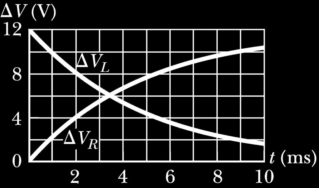
28 Example 32.2 (C) Compare the potential difference across the resistor with that across the inductor. Solution: At the instant the switch is closed, there is no current and therefore no potential difference across the resistor. At this instant, the battery voltage appears entirely across the inductor in the form of a back emf of 12.0 V as the inductor tries to maintain the zero-current condition. (The top end of the inductor in Active Fig 32.2 is at a higher electric potential than the bottom end.) As time passes, the emf across the inductor decreases and the current in the resistor (and hence the voltage across it) increases as shown in Figure The sum of the two voltages at all times is 12.0 V. 28

29 Example
30 Energy in a Magnetic Field In a circuit with an inductor, the battery must supply more energy than in a circuit without an inductor. Part of the energy supplied by the battery appears as internal energy in the resistor. The remaining energy is stored in the magnetic field of the inductor. Section
31 Energy in a Magnetic Field, cont. Looking at this energy (in terms of rate) 2 di Iε I R LI dt (32.11) Ie is the rate at which energy is being supplied by the battery. I 2 R is the rate at which the energy is being delivered to the resistor. Therefore, LI (di/dt) must be the rate at which the energy is being stored in the magnetic field. Section
32 Energy in a Magnetic Field, final Let U denote the energy stored in the inductor at any time. The rate at which the energy is stored is du dt LI di dt To find the total energy, integrate and I 1 U L I di LI (32.12) Section
33 Energy Density of a Magnetic Field Given U = ½ LI 2 and assume (for simplicity) a solenoid with L = 0 n 2 V Since V is the volume of the solenoid, the magnetic energy density, u B is B B U 0n V V 2 0n 2 0 u B U V 2 B 2 This applies to any region in which a magnetic field exists (not just the solenoid). 0 (32.13) (32.14) Section
34 Energy Storage Summary A resistor, inductor and capacitor all store energy through different mechanisms. Charged capacitor Stores energy as electric potential energy Inductor When it carries a current, stores energy as magnetic potential energy Resistor Energy delivered is transformed into internal energy Section


35 Example: The Coaxial Cable Calculate L of a length l for the cable The total flux is b 0I B B da a 2 r 0I b Therefore, L is ln 2 a dr L B 0 b ln I 2 a Section
36 Quick Quiz 32.3 You are performing an experiment that requires the highestpossible magnetic energy density in the interior of a very long current-carrying solenoid. Which of the following adjustments increases the energy density? (More than one choice may be correct.) (a) increasing the number of turns per unit length on the solenoid (b) increasing the cross- sectional area of the solenoid (c) increasing only the length of the solenoid while keeping the number of turns per unit length fixed (d) increasing the current in the solenoid. Answer: (a), (d) 36
37 Example 32.3 Consider once again the RL circuit shown in Active Figure 32.2, with switch S 2 at position a and the current having reached its steady-state value. When S 2 is thrown to position b, the current in the right-hand loop decays exponentially / with time according to the expression I I t, where I i = ie t e/r is the initial current in the circuit and t = L/R is the time constant. 5how that all the energy initially stored in the magnetic field of the inductor appears as internal energy in the resistor as the current decays to zero. 37
38 Example 32.3 Solution: du I R ( I e ) R I Re dt 2 Rt / L Rt / L i i 2 2 Rt / L 2 2 Rt / L 0 i i 0 U I Re dt I R e dt L 1 U I R LI 2R i i 38


39 Example 32.4 Coaxial cables are often used to connect electrical devices, such as your video system, and in receiving signals in television cable systems. Model a long coaxial cable as a thin, cylindrical conducting shell of radius b concentric with a solid cylinder of radius a as in Figure The conductors carry the same current I in opposite directions. Calculate the inductance L of a length l of this cable. 39
40 Example 32.4 Solution: BdA B B dr b 0I 0I bdr 0I b B dr = ln a 2 r 2 a r 2 a B 0 b L ln I 2 a 40
41 Mutual Inductance The magnetic flux through the area enclosed by a circuit often varies with time because of time-varying currents in nearby circuits. This process is known as mutual induction because it depends on the interaction of two circuits. Section

42 Mutual Inductance, cont. The current in coil 1 sets up a magnetic field. Some of the magnetic field lines pass through coil 2. Coil 1 has a current I 1 and N 1 turns. Coil 2 has N 2 turns. Section
43 Mutual Inductance, final The mutual inductance M 12 of coil 2 with respect to coil 1 is M 12 N I (32.15) Mutual inductance depends on the geometry of both circuits and on their orientation with respect to each other. Section
44 Induced emf in Mutual Inductance If current I 1 varies with time, the emf induced by coil 1 in coil 2 is ε N d dt M di dt (32.16) If the current is in coil 2, there is a mutual inductance M 21. If current 2 varies with time, the emf induced by coil 2 in coil 1 is ε di M dt (32.17) Section
45 Induced emf in Mutual Inductance, cont. In mutual induction, the emf induced in one coil is always proportional to the rate at which the current in the other coil is changing. The mutual inductance in one coil is equal to the mutual inductance in the other coil. M 12 = M 21 = M The induced emf s can be expressed as ε M di dt and M di dt ε Section
46 Quick Quiz 32.4 In Figure 32.8, coil 1 is moved closer to coil 2, with the orientation of both coils remaining fixed. Because of this movement, the mutual induction of the two coils (a) increases, (b) decreases, or (c) is unaffected. Answer: (a) 46
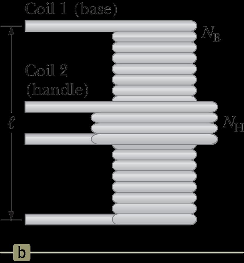
47 Example 32.5 An electric toothbrush has a base designed to hold the toothbrush handle when not in use. As shown in Figure 32.9a, the handle has a cylindrical hole that fits loosely over a matching cylinder on the base. When the handle is placed on the base, a changing current in a solenoid inside the base cylinder induces a current in a coil inside the handle. This induced current charges the battery in the handle. We can model the base as a solenoid of length l with N B turns (Fig. 32.9b), carrying a current I, and having a cross-sectional area A. The handle coil contains N H turns and completely surrounds the base coil. Find the mutual inductance of the system. 47

48 Example
49 Example 32.5 Solution: B 0 N B I M N N BA N N I I H BH H B H 0 A 49
50 LC Circuits A capacitor is connected to an inductor in an LC circuit. Assume the capacitor is initially charged and then the switch is closed. Assume no resistance and no energy losses to radiation. Section
51 Oscillations in an LC Circuit Under the previous conditions, the current in the circuit and the charge on the capacitor oscillate between maximum positive and negative values. With zero resistance, no energy is transformed into internal energy. Ideally, the oscillations in the circuit persist indefinitely. The idealizations are no resistance and no radiation. Section
52 Oscillations in an LC Circuit The capacitor is fully charged. The energy U in the circuit is stored in the electric field of the capacitor. The energy is equal to Q 2 max / 2C. The current in the circuit is zero. No energy is stored in the inductor. The switch is closed. 52
53 Oscillations in an LC Circuit, cont. The current is equal to the rate at which the charge changes on the capacitor. As the capacitor discharges, the energy stored in the electric field decreases. Since there is now a current, some energy is stored in the magnetic field of the inductor. Energy is transferred from the electric field to the magnetic field. Section
54 Oscillations in an LC Circuit, cont. Eventually, the capacitor becomes fully discharged. It stores no energy. All of the energy is stored in the magnetic field of the inductor. The current reaches its maximum value. The current now decreases in magnitude, recharging the capacitor with its plates having opposite their initial polarity. 54
55 Oscillations in an LC Circuit, final The capacitor becomes fully charged and the cycle repeats. The energy continues to oscillate between the inductor and the capacitor. The total energy stored in the LC circuit remains constant in time and equals. 2 Q 1 U UC U L LI 2C 2 2 (32.18) Section
56 LC Circuit Analogy to Spring-Mass System, 1 The potential energy ½ kx 2 stored in the spring is analogous to the electric potential energy (Q max ) 2 /(2C) stored in the capacitor. All the energy is stored in the capacitor at t = 0. This is analogous to the spring stretched to its amplitude. Section
57 LC Circuit Analogy to Spring-Mass System, 2 The kinetic energy (½ mv 2 ) of the spring is analogous to the magnetic energy (½ LI 2 ) stored in the inductor. At t = ¼ T, all the energy is stored as magnetic energy in the inductor. The maximum current occurs in the circuit. This is analogous to the mass at equilibrium. Section
58 LC Circuit Analogy to Spring-Mass System, 3 At t = ½ T, the energy in the circuit is completely stored in the capacitor. The polarity of the capacitor is reversed. This is analogous to the spring stretched to A. Section
59 LC Circuit Analogy to Spring-Mass System, 4 At t = ¾ T, the energy is again stored in the magnetic field of the inductor. This is analogous to the mass again reaching the equilibrium position. Section
60 LC Circuit Analogy to Spring-Mass System, 5 At t = T, the cycle is completed The conditions return to those identical to the initial conditions. At other points in the cycle, energy is shared between the electric and magnetic fields. Section
61 If you can't see the image above, please install Shockwave Flash Player. If this active figure can t auto-play, please click right button, then click play : Oscillations in an LC Circuit In this animation you can study energy transfer in a nonradiating, resistanceless LC circuit. The oscillations of the LC circuit are an electromagnetic analog to the mechanical oscillations of the block-spring systems that we studied in Chapter 15. Adjust the values in this animation to observe the effect on the oscillating current. 61
62 Time Functions of an LC Circuit In an LC circuit, charge can be expressed as a function of time. Q = Q max cos ( t + ) (32.21) This is for an ideal LC circuit The angular frequency,, of the circuit depends on the inductance and the capacitance. It is the natural frequency of oscillation of the circuit. 1 LC (32.22) Section
63 Time Functions of an LC Circuit, cont. The current can be expressed as a function of time: dq I Q sin( ) max t dt (32.23) The total energy can be expressed as a function of time: 2 Qmax U UC U L cos t LImax sin t 2c 2 (32.26) Section

64 Charge and Current in an LC Circuit The charge on the capacitor oscillates between Q max and Q max. The current in the inductor oscillates between I max and I max. Q and I are 90º out of phase with each other So when Q is a maximum, I is zero, etc. Section

65 Energy in an LC Circuit Graphs The energy continually oscillates between the energy stored in the electric and magnetic fields. When the total energy is stored in one field, the energy stored in the other field is zero. Section
66 Notes About Real LC Circuits In actual circuits, there is always some resistance. Therefore, there is some energy transformed to internal energy. Radiation is also inevitable in this type of circuit. The total energy in the circuit continuously decreases as a result of these processes. Section
67 Quick Quiz 32.5 (i) At an instant of time during the oscillations of an LC circuit, the current is at its maximum value. At this instant, what happens to the voltage across the capacitor? (a) It is different from that across the inductor. (b) It is zero. (c) It has its maximum value. (d) It is impossible to determine. (ii) At an instant of time during the oscillations of an LC circuit, the current is momentarily zero. From the same choices, describe the voltage across the capacitor at this instant. Answer: (i) (b) (ii) (c) 67

68 Example 32.6 In Figure 32.14, the battery has an emf of 12.0 V, the inductance is 2.81 mh, and the capacitance is 9.00 pf. The switch has been set to position a for a long time so that the capacitor is charged. The switch is then thrown to position b, removing the battery from the circuit and connecting the capacitor directly across the inductor. 68
69 Example 32.6 (A) Find the frequency of oscillation of the circuit. Solution: 1 f 2 2 LC 1 f /2 2 [( H)( F)] (B) What are the maximum values of charge on the capacitor and current in the circuit? Solution: Q C V ( F)(12.0 V) C max I Q fq max max 2 max (2 10 s )( C) A Hz 69

70 The RLC Circuit A circuit containing a resistor, an inductor and a capacitor is called an RLC Circuit. Assume the resistor represents the total resistance of the circuit. Section

71 If you can't see the image above, please install Shockwave Flash Player. If this active figure can t auto-play, please click right button, then click play : The RLC Circuit This RLC circuit consists of a resistor, an inductor, and a capacitor connected in series. When the animation opens, switch S 1 is closed and S 2 is open so that the capacitor has an initial charge. When you open S 1 and close S 2, a current is established and the resistor causes transformation to internal energy. 71
72 RLC Circuit, Analysis The total energy is not constant, since there is a transformation to internal energy in the resistor at the rate of du/dt = I 2 R. Radiation losses are still ignored The circuit s operation can be expressed as L d 2 Q R dq Q 0 2 dt dt C (32.29) Section
73 RLC Circuit Compared to Damped Oscillators The RLC circuit is analogous to a damped harmonic oscillator. When R = 0 The circuit reduces to an LC circuit and is equivalent to no damping in a mechanical oscillator. Section
74 RLC Circuit Compared to Damped Oscillators When R is small: The RLC circuit is analogous to light damping in a mechanical oscillator. Q = Q max e Rt/2L cos d t d is the angular frequency of oscillation for the circuit and (32.31) d 1 R LC 2L 2 1/ 2 (32.32) 74
75 RLC Circuit Compared to Damped Oscillators, cont. When R is very large, the oscillations damp out very rapidly. There is a critical value of R above which no oscillations occur. RC 4 L / C If R = R C, the circuit is said to be critically damped. When R > R C, the circuit is said to be overdamped. Section

76 Damped RLC Circuit, Graph The maximum value of Q decreases after each oscillation. R < R C This is analogous to the amplitude of a damped spring-mass system. Section
77 Summary: Analogies Between Electrical and Mechanic Systems Section
Chapter 32. Inductance
 Chapter 32 Inductance Joseph Henry 1797 1878 American physicist First director of the Smithsonian Improved design of electromagnet Constructed one of the first motors Discovered self-inductance Unit of
Self-inductance A time-varying current in a circuit produces an induced emf opposing the emf that initially set up the time-varying current.
 Inductance Self-inductance A time-varying current in a circuit produces an induced emf opposing the emf that initially set up the time-varying current. Basis of the electrical circuit element called an
Active Figure 32.3 (SLIDESHOW MODE ONLY)
") RL Circuit, Analysis An RL circuit contains an inductor and a resistor When the switch is closed (at time t = 0), the current begins to increase At the same time, a back emf is induced in the inductor
RL Circuit, Analysis An RL circuit contains an inductor and a resistor When the switch is closed (at time t = 0), the current begins to increase At the same time, a back emf is induced in the inductor
Inductance, RL and RLC Circuits
 Inductance, RL and RLC Circuits Inductance Temporarily storage of energy by the magnetic field When the switch is closed, the current does not immediately reach its maximum value. Faraday s law of electromagnetic
Inductance, Inductors, RL Circuits & RC Circuits, LC, and RLC Circuits
 Inductance, Inductors, RL Circuits & RC Circuits, LC, and RLC Circuits Self-inductance A time-varying current in a circuit produces an induced emf opposing the emf that initially set up the timevarying
Inductance. Chapter Outline Self-Inductance 32.2 RL Circuits 32.3 Energy in a Magnetic Field
 P U Z Z L E R The marks in the pavement are part of a sensor that controls the traffic lights at this intersection. What are these marks, and how do they detect when a car is waiting at the light? ( David
Chapter 32. nductance
 Chapter 32 nductance C HAP T E R O UT N E 321 elf-nductance 322 R Circuits 323 Energy in a Magnetic Field 324 Mutual nductance 325 Oscillations in an Circuit 326 The R Circuit An airport metal detector
Handout 10: Inductance. Self-Inductance and inductors
 1 Handout 10: Inductance Self-Inductance and inductors In Fig. 1, electric current is present in an isolate circuit, setting up magnetic field that causes a magnetic flux through the circuit itself. This
Chapter 30 Inductance and Electromagnetic Oscillations
 Chapter 30 Inductance and Electromagnetic Oscillations Units of Chapter 30 30.1 Mutual Inductance: 1 30.2 Self-Inductance: 2, 3, & 4 30.3 Energy Stored in a Magnetic Field: 5, 6, & 7 30.4 LR Circuit: 8,
Slide 1 / 26. Inductance by Bryan Pflueger
 Slide 1 / 26 Inductance 2011 by Bryan Pflueger Slide 2 / 26 Mutual Inductance If two coils of wire are placed near each other and have a current passing through them, they will each induce an emf on one
Electromagnetic Induction Faraday s Law Lenz s Law Self-Inductance RL Circuits Energy in a Magnetic Field Mutual Inductance
 Lesson 7 Electromagnetic Induction Faraday s Law Lenz s Law Self-Inductance RL Circuits Energy in a Magnetic Field Mutual Inductance Oscillations in an LC Circuit The RLC Circuit Alternating Current Electromagnetic
Chapter 31. Faraday s Law
 Chapter 31 Faraday s Law 1 Ampere s law Magnetic field is produced by time variation of electric field B s II I d d μ o d μo με o o E ds E B Induction A loop of wire is connected to a sensitive ammeter
Electromagnetic Induction (Chapters 31-32)
") Electromagnetic Induction (Chapters 31-3) The laws of emf induction: Faraday s and Lenz s laws Inductance Mutual inductance M Self inductance L. Inductors Magnetic field energy Simple inductive circuits
Electromagnetic Induction (Chapters 31-3) The laws of emf induction: Faraday s and Lenz s laws Inductance Mutual inductance M Self inductance L. Inductors Magnetic field energy Simple inductive circuits
Chapter 31. Faraday s Law
 Chapter 31 Faraday s Law 1 Ampere s law Magnetic field is produced by time variation of electric field dφ B ( I I ) E d s = µ o + d = µ o I+ µ oεo ds E B 2 Induction A loop of wire is connected to a sensitive
Chapter 30. Inductance
 Chapter 30 Inductance Self Inductance When a time dependent current passes through a coil, a changing magnetic flux is produced inside the coil and this in turn induces an emf in that same coil. This induced
ELECTROMAGNETIC INDUCTION AND FARADAY S LAW
 ELECTROMAGNETIC INDUCTION AND FARADAY S LAW Magnetic Flux The emf is actually induced by a change in the quantity called the magnetic flux rather than simply py by a change in the magnetic field Magnetic
Chapter 30 Inductance
 Chapter 30 Inductance In this chapter we investigate the properties of an inductor in a circuit. There are two kinds of inductance mutual inductance and self-inductance. An inductor is formed by taken
Sliding Conducting Bar
 Motional emf, final For equilibrium, qe = qvb or E = vb A potential difference is maintained between the ends of the conductor as long as the conductor continues to move through the uniform magnetic field
Inductance. Slide 2 / 26. Slide 1 / 26. Slide 4 / 26. Slide 3 / 26. Slide 6 / 26. Slide 5 / 26. Mutual Inductance. Mutual Inductance.
 Slide 1 / 26 Inductance 2011 by Bryan Pflueger Slide 2 / 26 Mutual Inductance If two coils of wire are placed near each other and have a current passing through them, they will each induce an emf on one
Chapter 30. Inductance. PowerPoint Lectures for University Physics, 14th Edition Hugh D. Young and Roger A. Freedman Lectures by Jason Harlow
 Chapter 30 Inductance PowerPoint Lectures for University Physics, 14th Edition Hugh D. Young and Roger A. Freedman Lectures by Jason Harlow Learning Goals for Chapter 30 Looking forward at how a time-varying
Ch. 23 Electromagnetic Induction, AC Circuits, And Electrical Technologies
 Ch. 23 Electromagnetic Induction, AC Circuits, And Electrical Technologies Induced emf - Faraday s Experiment When a magnet moves toward a loop of wire, the ammeter shows the presence of a current When
Electromagnetic Oscillations and Alternating Current. 1. Electromagnetic oscillations and LC circuit 2. Alternating Current 3.
 Electromagnetic Oscillations and Alternating Current 1. Electromagnetic oscillations and LC circuit 2. Alternating Current 3. RLC circuit in AC 1 RL and RC circuits RL RC Charging Discharging I = emf R
Lecture 39. PHYC 161 Fall 2016
 Lecture 39 PHYC 161 Fall 016 Announcements DO THE ONLINE COURSE EVALUATIONS - response so far is < 8 % Magnetic field energy A resistor is a device in which energy is irrecoverably dissipated. By contrast,
Inductance, RL Circuits, LC Circuits, RLC Circuits
 Inductance, R Circuits, C Circuits, RC Circuits Inductance What happens when we close the switch? The current flows What does the current look like as a function of time? Does it look like this? I t Inductance
PHYS 1441 Section 001 Lecture #23 Monday, Dec. 4, 2017
 PHYS 1441 Section 1 Lecture #3 Monday, Dec. 4, 17 Chapter 3: Inductance Mutual and Self Inductance Energy Stored in Magnetic Field Alternating Current and AC Circuits AC Circuit W/ LRC Chapter 31: Maxwell
INDUCTANCE Self Inductance
 NDUTANE 3. Self nductance onsider the circuit shown in the Figure. When the switch is closed the current, and so the magnetic field, through the circuit increases from zero to a specific value. The increasing
Electricity and Magnetism Energy of the Magnetic Field Mutual Inductance
 Electricity and Magnetism Energy of the Magnetic Field Mutual Inductance Lana Sheridan De Anza College Mar 14, 2018 Last time inductors resistor-inductor circuits Overview wrap up resistor-inductor circuits
Chapter 30 INDUCTANCE. Copyright 2012 Pearson Education Inc.
 Chapter 30 INDUCTANCE Goals for Chapter 30 To learn how current in one coil can induce an emf in another unconnected coil To relate the induced emf to the rate of change of the current To calculate the
Lecture 27: FRI 20 MAR
 Physics 2102 Jonathan Dowling Lecture 27: FRI 20 MAR Ch.30.7 9 Inductors & Inductance Nikolai Tesla Inductors: Solenoids Inductors are with respect to the magnetic field what capacitors are with respect
Chapter 14 Inductance 627
 Chapter 14 Inductance 627 14 INDUCTANCE Figure 14.1 A smartphone charging mat contains a coil that receives alternating current, or current that is constantly increasing and decreasing. The varying current
PHYS 241 EXAM #2 November 9, 2006
 1. ( 5 points) A resistance R and a 3.9 H inductance are in series across a 60 Hz AC voltage. The voltage across the resistor is 23 V and the voltage across the inductor is 35 V. Assume that all voltages
11 Chapter. Inductance and Magnetic Energy
 11 Chapter Inductance and Magnetic Energy 11.1 Mutual Inductance... 11-3 Example 11.1 Mutual Inductance of Two Concentric Co-planar Loops... 11-5 11.2 Self-Inductance... 11-6 Example 11.2 Self-Inductance
Physics for Scientists & Engineers 2
 Electromagnetic Oscillations Physics for Scientists & Engineers Spring Semester 005 Lecture 8! We have been working with circuits that have a constant current a current that increases to a constant current
General Physics (PHY 2140)
") General Physics (PHY 2140) Lecture 10 6/12/2007 Electricity and Magnetism Induced voltages and induction Self-Inductance RL Circuits Energy in magnetic fields AC circuits and EM waves Resistors, capacitors
General Physics (PHY 2140) Lecture 10 6/12/2007 Electricity and Magnetism Induced voltages and induction Self-Inductance RL Circuits Energy in magnetic fields AC circuits and EM waves Resistors, capacitors
Chapter 30 Self Inductance, Inductors & DC Circuits Revisited
 Chapter 30 Self Inductance, Inductors & DC Circuits Revisited Self-Inductance and Inductors Self inductance determines the magnetic flux in a circuit due to the circuit s own current. B = LI Every circuit
Chapter 28. Direct Current Circuits
 Chapter 28 Direct Current Circuits Circuit Analysis Simple electric circuits may contain batteries, resistors, and capacitors in various combinations. For some circuits, analysis may consist of combining
PHYS 202 Notes, Week 6
 PHYS 202 Notes, Week 6 Greg Christian February 23 & 25, 2016 Last updated: 02/25/2016 at 12:36:40 This week we learn about electromagnetic induction. Magnetic Induction This section deals with magnetic
Chapter 5. Electromagnetic Induction
 Chapter 5 Electromagnetic Induction Overview In the last chapter, we studied how a current produces a magnetic field. Here we will study the reverse effect: A magnetic field can produce an electric field
Last time. Ampere's Law Faraday s law
 Last time Ampere's Law Faraday s law 1 Faraday s Law of Induction (More Quantitative) The magnitude of the induced EMF in conducting loop is equal to the rate at which the magnetic flux through the surface
Induction_P1. 1. [1 mark]
![Induction_P1. 1. [1 mark]](/thumbs/88/115570773.jpg "Induction_P1. 1. [1 mark]") Induction_P1 1. [1 mark] Two identical circular coils are placed one below the other so that their planes are both horizontal. The top coil is connected to a cell and a switch. The switch is closed and
Induction_P1 1. [1 mark] Two identical circular coils are placed one below the other so that their planes are both horizontal. The top coil is connected to a cell and a switch. The switch is closed and
Module 22 and 23: Section 11.1 through Section 11.4 Module 24: Section 11.4 through Section Table of Contents
 Module and 3: Section 11.1 through Section 11.4 Module 4: Section 11.4 through Section 11.13 1 Table of Contents Inductance and Magnetic Energy... 11-3 11.1 Mutual Inductance... 11-3 Example 11.1 Mutual
Chapter 5: Electromagnetic Induction
 Chapter 5: Electromagnetic Induction 5.1 Magnetic Flux 5.1.1 Define and use magnetic flux Magnetic flux is defined as the scalar product between the magnetic flux density, B with the vector of the area,
Physics 1302W.400 Lecture 33 Introductory Physics for Scientists and Engineering II
 Physics 1302W.400 Lecture 33 Introductory Physics for Scientists and Engineering II In today s lecture, we will discuss generators and motors. Slide 30-1 Announcement Quiz 4 will be next week. The Final
What happens when things change. Transient current and voltage relationships in a simple resistive circuit.
 Module 4 AC Theory What happens when things change. What you'll learn in Module 4. 4.1 Resistors in DC Circuits Transient events in DC circuits. The difference between Ideal and Practical circuits Transient
Physics 420 Fall 2004 Quiz 1 Wednesday This quiz is worth 6 points. Be sure to show your work and label your final answers.
 Quiz 1 Wednesday This quiz is worth 6 points. Be sure to show your work and label your final answers. 1. A charge q 1 = +5.0 nc is located on the y-axis, 15 µm above the origin, while another charge q
Yell if you have any questions
 Class 31: Outline Hour 1: Concept Review / Overview PRS Questions possible exam questions Hour : Sample Exam Yell if you have any questions P31 1 Exam 3 Topics Faraday s Law Self Inductance Energy Stored
Magnetic Induction Faraday, Lenz, Mutual & Self Inductance Maxwell s Eqns, E-M waves. Reading Journals for Tuesday from table(s)
") PHYS 2015 -- Week 12 Magnetic Induction Faraday, Lenz, Mutual & Self Inductance Maxwell s Eqns, E-M waves Reading Journals for Tuesday from table(s) WebAssign due Friday night For exclusive use in PHYS
PHYS 2015 -- Week 12 Magnetic Induction Faraday, Lenz, Mutual & Self Inductance Maxwell s Eqns, E-M waves Reading Journals for Tuesday from table(s) WebAssign due Friday night For exclusive use in PHYS
RLC Circuit (3) We can then write the differential equation for charge on the capacitor. The solution of this differential equation is
 We can then write the differential equation for charge on the capacitor. The solution of this differential equation is") RLC Circuit (3) We can then write the differential equation for charge on the capacitor The solution of this differential equation is (damped harmonic oscillation!), where 25 RLC Circuit (4) If we charge
RLC Circuit (3) We can then write the differential equation for charge on the capacitor The solution of this differential equation is (damped harmonic oscillation!), where 25 RLC Circuit (4) If we charge
Chapter 30 Examples : Inductance (sections 1 through 6) Key concepts: (See chapter 29 also.)
 Key concepts: (See chapter 29 also.)") Chapter 30 Examples : Inductance (sections 1 through 6) Key concepts: (See chapter 29 also.) ξ 2 = MdI 1 /dt : A changing current in a coil of wire (1) will induce an EMF in a second coil (2) placed nearby.
Chapter 30 Examples : Inductance (sections 1 through 6) Key concepts: (See chapter 29 also.) ξ 2 = MdI 1 /dt : A changing current in a coil of wire (1) will induce an EMF in a second coil (2) placed nearby.
Induction and Inductance
 Induction and Inductance Key Contents Faraday s law: induced emf Induction and energy transfer Inductors and inductance RL circuits Magnetic energy density The First Experiment 1. A current appears only
1 2 U CV. K dq I dt J nqv d J V IR P VI
 o 5 o T C T F 3 9 T K T o C 73.5 L L T V VT Q mct nct Q F V ml F V dq A H k TH TC L pv nrt 3 Ktr nrt 3 CV R ideal monatomic gas 5 CV R ideal diatomic gas w/o vibration V W pdv V U Q W W Q e Q Q e Carnot
CHAPTER 5: ELECTROMAGNETIC INDUCTION
 CHAPTER 5: ELECTROMAGNETIC INDUCTION PSPM II 2005/2006 NO. 5 5. An AC generator consists a coil of 30 turns with cross sectional area 0.05 m 2 and resistance 100 Ω. The coil rotates in a magnetic field
Chapter 21 Magnetic Induction Lecture 12
 Chapter 21 Magnetic Induction Lecture 12 21.1 Why is it called Electromagnetism? 21.2 Magnetic Flux and Faraday s Law 21.3 Lenz s Law and Work-Energy Principles 21.4 Inductance 21.5 RL Circuits 21.6 Energy
Chapter 30. Induction and Inductance
 Chapter 30 Induction and Inductance 30.2: First Experiment: 1. A current appears only if there is relative motion between the loop and the magnet (one must move relative to the other); the current disappears
AP Physics C. Magnetism - Term 4
 AP Physics C Magnetism - Term 4 Interest Packet Term Introduction: AP Physics has been specifically designed to build on physics knowledge previously acquired for a more in depth understanding of the world
PHYSICS. Chapter 30 Lecture FOR SCIENTISTS AND ENGINEERS A STRATEGIC APPROACH 4/E RANDALL D. KNIGHT
 PHYSICS FOR SCIENTISTS AND ENGINEERS A STRATEGIC APPROACH 4/E Chapter 30 Lecture RANDALL D. KNIGHT Chapter 30 Electromagnetic Induction IN THIS CHAPTER, you will learn what electromagnetic induction is
Lecture Sound Waves Review. Physics Help Q&A: tutor.leiacademy.org. Force on a Charge Moving in a Magnetic Field
 Lecture 1101 Sound Waves Review Physics Help Q&A: tutor.leiacademy.org Force on a Charge Moving in a Magnetic Field A charge moving in a magnetic field can have a magnetic force exerted by the B-field.
A 2. The potential difference across the capacitor is F m N m /C m. R R m m R m R m 0
 30.53. Model: The charged metal spheres are isolated and far from each other and anything else. Solve: (a) The charge on a sphere of radius r, charged to a potential V 0 is given by the equations: The
ECE2262 Electric Circuits. Chapter 6: Capacitance and Inductance
 ECE2262 Electric Circuits Chapter 6: Capacitance and Inductance Capacitors Inductors Capacitor and Inductor Combinations Op-Amp Integrator and Op-Amp Differentiator 1 CAPACITANCE AND INDUCTANCE Introduces
Physics 1308 Exam 2 Summer 2015
 Physics 1308 Exam 2 Summer 2015 E2-01 2. The direction of the magnetic field in a certain region of space is determined by firing a test charge into the region with its velocity in various directions in
Exam 2 Solutions. Note that there are several variations of some problems, indicated by choices in parentheses.
 Exam 2 Solutions Note that there are several variations of some problems, indicated by choices in parentheses. Problem 1 Part of a long, straight insulated wire carrying current i is bent into a circular
Electromagnetic Induction and Waves (Chapters 33-34)
") Electromagnetic nduction and Waves (Chapters 33-34) The laws of emf induction: Faraday s and Lenz s laws Concepts of classical electromagnetism. Maxwell equations nductance Mutual inductance M Self inductance
Electromagnetic nduction and Waves (Chapters 33-34) The laws of emf induction: Faraday s and Lenz s laws Concepts of classical electromagnetism. Maxwell equations nductance Mutual inductance M Self inductance
University Physics 227N/232N Ch 27: Inductors, towards Ch 28: AC Circuits Quiz and Homework Due This Week Exam Next Wednesday!
 Vector pointing OUT of page University Physics 227N/232N Ch 27: Inductors, towards Ch 28: AC Circuits Quiz and Homework Due This Week Exam Next Wednesday! (April 9) Dr. Todd Satogata (ODU/Jefferson Lab)
Louisiana State University Physics 2102, Exam 3, November 11, 2010.
 Name: Instructor: Louisiana State University Physics 2102, Exam 3, November 11, 2010. Please be sure to write your name and class instructor above. The test consists of 3 questions (multiple choice), and
Version 001 HW 22 EM Induction C&J sizemore (21301jtsizemore) 1
 1") Version 001 HW 22 EM Induction C&J sizemore (21301jtsizemore) 1 This print-out should have 35 questions. Multiple-choice questions may continue on the next column or page find all choices before answering.
Version 001 HW 22 EM Induction C&J sizemore (21301jtsizemore) 1 This print-out should have 35 questions. Multiple-choice questions may continue on the next column or page find all choices before answering.
Chapter 30. Induction and Inductance
 Chapter 30 Induction and Inductance 30.2: First Experiment: 1. A current appears only if there is relative motion between the loop and the magnet (one must move relative to the other); the current disappears
Chapter 23 Magnetic Flux and Faraday s Law of Induction
 Chapter 23 Magnetic Flux and Faraday s Law of Induction 1 Overview of Chapter 23 Induced Electromotive Force Magnetic Flux Faraday s Law of Induction Lenz s Law Mechanical Work and Electrical Energy Generators
PES 1120 Spring 2014, Spendier Lecture 35/Page 1
 PES 0 Spring 04, Spendier Lecture 35/Page Today: chapter 3 - LC circuits We have explored the basic physics of electric and magnetic fields and how energy can be stored in capacitors and inductors. We
AP Physics C Mechanics Objectives
 AP Physics C Mechanics Objectives I. KINEMATICS A. Motion in One Dimension 1. The relationships among position, velocity and acceleration a. Given a graph of position vs. time, identify or sketch a graph
Mansfield Independent School District AP Physics C: Electricity and Magnetism Year at a Glance
 Mansfield Independent School District AP Physics C: Electricity and Magnetism Year at a Glance First Six-Weeks Second Six-Weeks Third Six-Weeks Lab safety Lab practices and ethical practices Math and Calculus
Exam 3 Topics. Displacement Current Poynting Vector. Faraday s Law Self Inductance. Circuits. Energy Stored in Inductor/Magnetic Field
 Exam 3 Topics Faraday s Law Self Inductance Energy Stored in Inductor/Magnetic Field Circuits LR Circuits Undriven (R)LC Circuits Driven RLC Circuits Displacement Current Poynting Vector NO: B Materials,
Physics 240 Fall 2005: Exam #3 Solutions. Please print your name: Please list your discussion section number: Please list your discussion instructor:
 Physics 4 Fall 5: Exam #3 Solutions Please print your name: Please list your discussion section number: Please list your discussion instructor: Form #1 Instructions 1. Fill in your name above. This will
Chapter 32 Solutions
 Chapter 3 Solutions *3. ε = L I t = (3.00 0 3 H).50 A 0.00 A 0.00 s =.95 0 V = 9.5 mv 3. Treating the telephone cord as a solenoid, we have: L = µ 0 N A l = (4π 0 7 T m/a)(70.0) (π)(6.50 0 3 m) 0.600 m
Part 4: Electromagnetism. 4.1: Induction. A. Faraday's Law. The magnetic flux through a loop of wire is
 1 Part 4: Electromagnetism 4.1: Induction A. Faraday's Law The magnetic flux through a loop of wire is Φ = BA cos θ B A B = magnetic field penetrating loop [T] A = area of loop [m 2 ] = angle between field
The self-inductance depends on the geometric shape of the coil. An inductor is a coil of wire used in a circuit to provide inductance is an inductor.
 Self Inductance and Mutual Inductance Script Self-Inductance Consider a coil carrying a current i. The current in the coil produces a magnetic field B that varies from point to point in the coil. The magnetic
Electromagnetic Induction and AC Circuits
 HAPTER22 C. Return to Table of Contents Electromagnetic Induction and AC Circuits This electric generator, shown being in - spected, will be used to provide electric power. Inside the generator a changing
Yell if you have any questions
 Class 36: Outline Hour 1: Concept Review / Overview PRS Questions Possible Exam Questions Hour : Sample Exam Yell if you have any questions P36-1 efore Starting All of your grades should now be posted
Yell if you have any questions
 Class 36: Outline Hour 1: Concept Review / Overview PRS Questions Possible Exam Questions Hour : Sample Exam Yell if you have any questions P36-1 Before Starting All of your grades should now be posted
David J. Starling Penn State Hazleton PHYS 212
 and and The term inductance was coined by Oliver Heaviside in February 1886. David J. Starling Penn State Hazleton PHYS 212 and We have seen electric flux: Φ E = E d A But we can define the magnetic flux
Physics 240 Fall 2005: Exam #3. Please print your name: Please list your discussion section number: Please list your discussion instructor:
 Physics 240 Fall 2005: Exam #3 Please print your name: Please list your discussion section number: Please list your discussion instructor: Form #1 Instructions 1. Fill in your name above 2. This will be
Lecture 22. Inductance. Magnetic Field Energy.
 Lecture 22. Inductance. Magnetic Field Energy. Outline: Self-induction and self-inductance. Inductance of a solenoid. The energy of a magnetic field. Alternative definition of inductance. Mutual Inductance.
General Physics - E&M (PHY 1308) - Lecture Notes. General Physics - E&M (PHY 1308) Lecture Notes
 - Lecture Notes. General Physics - E&M (PHY 1308) Lecture Notes") General Physics - E&M (PHY 1308) Lecture Notes Lecture 021: Self-Inductance and Inductors SteveSekula, 12 April 2011 (created 7 November 2010) Goals of this Lecture no tags Understand "self-inductance"
General Physics - E&M (PHY 1308) Lecture Notes Lecture 021: Self-Inductance and Inductors SteveSekula, 12 April 2011 (created 7 November 2010) Goals of this Lecture no tags Understand "self-inductance"
ECE2262 Electric Circuits. Chapter 6: Capacitance and Inductance
 ECE2262 Electric Circuits Chapter 6: Capacitance and Inductance Capacitors Inductors Capacitor and Inductor Combinations 1 CAPACITANCE AND INDUCTANCE Introduces two passive, energy storing devices: Capacitors
ELECTROMAGNETIC OSCILLATIONS AND ALTERNATING CURRENT
 Chapter 31: ELECTROMAGNETIC OSCILLATIONS AND ALTERNATING CURRENT 1 A charged capacitor and an inductor are connected in series At time t = 0 the current is zero, but the capacitor is charged If T is the
18 - ELECTROMAGNETIC INDUCTION AND ALTERNATING CURRENTS ( Answers at the end of all questions ) Page 1
 Page 1") ( Answers at the end of all questions ) Page ) The self inductance of the motor of an electric fan is 0 H. In order to impart maximum power at 50 Hz, it should be connected to a capacitance of 8 µ F (
( Answers at the end of all questions ) Page ) The self inductance of the motor of an electric fan is 0 H. In order to impart maximum power at 50 Hz, it should be connected to a capacitance of 8 µ F (
Lecture 30: WED 04 NOV
 Physics 2113 Jonathan Dowling Lecture 30: WED 04 NOV Induction and Inductance II Fender Stratocaster Solenoid Pickup F a r a d a y ' s E x p e r i m e n t s I n a s e r i e s o f e x p e r i m e n t s,
MAY/JUNE 2006 Question & Model Answer IN BASIC ELECTRICITY 194
 MAY/JUNE 2006 Question & Model Answer IN BASIC ELECTRICITY 194 Question 1 (a) List three sources of heat in soldering (b) state the functions of flux in soldering (c) briefly describe with aid of diagram
Louisiana State University Physics 2102, Exam 3 April 2nd, 2009.
 PRINT Your Name: Instructor: Louisiana State University Physics 2102, Exam 3 April 2nd, 2009. Please be sure to PRINT your name and class instructor above. The test consists of 4 questions (multiple choice),
Physics 1308 Exam 2 Summer Instructions
 Name: Date: Instructions All Students at SMU are under the jurisdiction of the Honor Code, which you have already signed a pledge to uphold upon entering the University. For this particular exam, you may
Physics 2B Spring 2010: Final Version A 1 COMMENTS AND REMINDERS:
 Physics 2B Spring 2010: Final Version A 1 COMMENTS AND REMINDERS: Closed book. No work needs to be shown for multiple-choice questions. 1. A charge of +4.0 C is placed at the origin. A charge of 3.0 C
Lecture 10 Induction and Inductance Ch. 30
 Lecture 10 Induction and Inductance Ch. 30 Cartoon - Faraday Induction Opening Demo - Thrust bar magnet through coil and measure the current Topics Faraday s Law Lenz s Law Motional Emf Eddy Currents LR
Chapter 20: Electromagnetic Induction. PHY2054: Chapter 20 1
 Chapter 20: Electromagnetic Induction PHY2054: Chapter 20 1 Electromagnetic Induction Magnetic flux Induced emf Faraday s Law Lenz s Law Motional emf Magnetic energy Inductance RL circuits Generators and
2006 #3 10. a. On the diagram of the loop below, indicate the directions of the magnetic forces, if any, that act on each side of the loop.
 1992 1 1994 2 3 3 1984 4 1991 5 1987 6 1980 8 7 9 2006 #3 10 1985 2006E3. A loop of wire of width w and height h contains a switch and a battery and is connected to a spring of force constant k, as shown
Electricity & Magnetism
 Ch 31 Faraday s Law Electricity & Magnetism Up to this point, we ve seen electric fields produced by electric charges... E =... and magnetic fields produced by moving charges... k dq E da = q in r 2 B
Induced e.m.f. on solenoid itself
 Induced e.m.f. Consider a loop of wire with radius r inside a long enoid Solenoid: N# of loops, ltotal length nn/l I I (t) What is the e.m.f. generated in the loop? Find inside enoid: E.m.f. generated
Calculus Relationships in AP Physics C: Electricity and Magnetism
 C: Electricity This chapter focuses on some of the quantitative skills that are important in your C: Mechanics course. These are not all of the skills that you will learn, practice, and apply during the
Chapter 31 Electromagnetic Oscillations and Alternating Current LC Oscillations, Qualitatively
 Chapter 3 Electromagnetic Oscillations and Alternating Current LC Oscillations, Qualitatively In the LC circuit the charge, current, and potential difference vary sinusoidally (with period T and angular
2005 AP PHYSICS C: ELECTRICITY AND MAGNETISM FREE-RESPONSE QUESTIONS
 2005 AP PHYSICS C: ELECTRICITY AND MAGNETISM In the circuit shown above, resistors 1 and 2 of resistance R 1 and R 2, respectively, and an inductor of inductance L are connected to a battery of emf e and
Physics Jonathan Dowling. Final Exam Review
 Physics 2102 Jonathan Dowling Physics 2102 Final Exam Review A few concepts: electric force, field and potential Electric force: What is the force on a charge produced by other charges? What is the force
Lecture 22. Inductance. Magnetic Field Energy.
 Lecture 22. Inductance. Magnetic Field Energy. Outline: Self-induction and self-inductance. Inductance of a solenoid. The energy of a magnetic field. Alternative definition of inductance. Mutual Inductance.