Circuit Analysis-II. Circuit Analysis-II Lecture # 5 Monday 23 rd April, 18
|
|
|
- Jacob Jordan
- 5 years ago
- Views:
Transcription

1 Circuit Analysis-II
2 Capacitors in AC Circuits
3 Introduction ü The instantaneous capacitor current is equal to the capacitance times the instantaneous rate of change of the voltage across the capacitor. i =C dv dt ü The faster the voltage across a capacitor changes, the greater the current.
4 Phase relationship of Current and Voltage ü When a sinusoidal voltage is applied across a capacitor: ü The voltage waveform has a maximum rate of change (dv/dt = max) at the zero crossings. ü A zero rate of change (dv/dt = 0) at the peaks.
5 Phase relationship of Current and Voltage (cont.) ü The phase relationship between the current and the voltage for the capacitor can be established from: i =C dv dt ü When dv / dt = 0, i is also zero because: i =C dv =C (0) = 0 dt ü When dv / dt is a positive-going maximum, i is a positive maximum; when dv / dt is a negative-going maximum, i is a negative maximum.
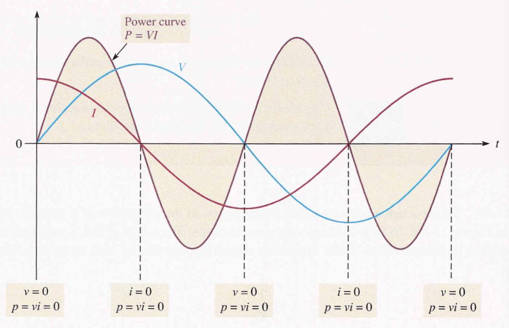
6 Phase relationship of Current and Voltage (cont.) ü A sinusoidal voltage always produces a sinusoidal current in a capacitive circuit. ü The voltage and current relationship is shown below:
7 Phase relationship of Current and Voltage (cont.) ü The current leads the voltage in phase by 90. ü This is always true in a purely capacitive circuit.
8 Capacitive Reactance
9 Capacitive Reactance ü Capacitive reactance is the opposition to sinusoidal current, expressed in ohms. ü The symbol for capacitive reactance is X C. ü The rate of change of the voltage is directly related to frequency. ü The faster the voltage changes, the higher the frequency. ü When frequency increases, dv / dt increases, and thus i increases. ü When frequency decreases, dv / dt decreases, and thus i decreases. i = ( ) C dv / dt i = C ( dv / dt )
10 Capacitive Reactance (cont.) ü An increase in i means that there is less opposition to current (X C is less). ü A decrease in i means a greater opposition to current (X C is greater). ü Therefore, X C is inversely proportional to i and thus inversely proportional to frequency i.e., 1/f. ü If dv/dt is constant and C is varied, an increase in C produces an increase in i, and a decrease in C produces a decrease in i. i =C (dv / dt ) and i =C (dv / dt )
11 Capacitive Reactance (cont.) ü An increase in i means less opposition (X C is less) and a decrease in i means greater opposition (X C is greater). ü Therefore, X C is inversely proportional to i and thus inversely proportional to capacitance. ü The capacitive reactance is inversely proportional to both f and C, i.e., ü Also, X C = 1 fc 1 X C = 2π fc
12 Capacitive Reactance (cont.) ü Capacitive reactance X C is in ohms when f is in hertz and C is in farads and 2π appears in the denominator as a constant of proportionality.
13 I = V X C Ohm s Law ü The reactance of a capacitor is analogous to the resistance of a resistor, as shown below: ü Both are expressed in ohms. Since both R and X C are forms of opposition to current, ohm s law applies to capacitive circuits as well as to resistive circuits. ü When applying ohm s law in ac circuits, both the current and the voltage are expressed in the same way i.e., both in rms, both in peak and so on.
14 Example #1 ü Determine the rms current:
15 Power in a Capacitor
16 Power
17 Instantaneous Power ü The product of v and i gives instantaneous power. ü Where v or i is zero, p is also zero, when both v and i are positive, p is also positive and when either v or i is positive and the other is negative, p is negative. ü When both v and i are negative, p is positive. ü Positive values of power indicate that energy stored by the capacitor. ü Negative values of power indicate that energy is returned from the capacitor to the source.
18 True Power ü Ideally all of the energy stored by a capacitor during the positive portion of the power cycle is returned to the source during the negative portion. ü No net energy is lost due to conversion to heat in the capacitor, so the true power is zero.
19 Reactive Power ü The rate at which a capacitor stores or returns energy is called its reactive power. ü The reactive power is a nonzero quantity, because at any instant in time, the capacitor is actually taking energy from the source or returning energy to it. ü Reactive power does not represent an energy loss. ü The following formulas apply: P r =V rms I rms P r = V 2 rms X C P r = I 2 rms X C
20 Example #2 ü Determine the true power and the reactive power:
21 Inductors in AC Circuits
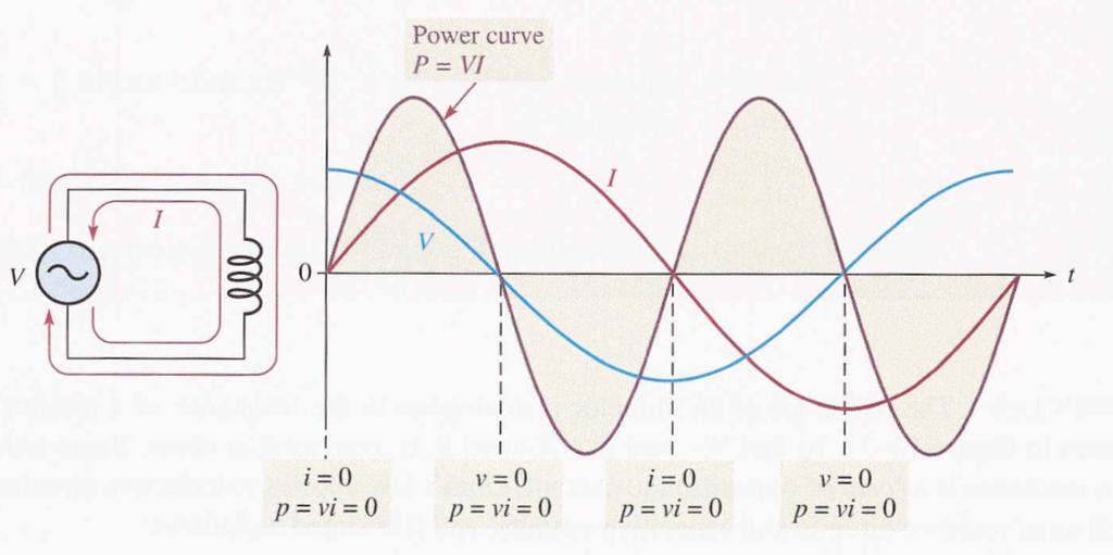
22 Phase Relationship of Current and Voltage ü The faster the current through an inductor changes, the greater the induced voltage will be. ü A sinusoidal current always induces a sinusoidal voltage in inductive circuits. ü Therefore the plot of voltage with respect to the current can be plotted if the points on the current curve at which the voltage is zero and those at which it is maximum are known. ü The voltage leads the current by 90. ü The phase relation of an inductor is shown below:
23 Phase Relationship of Current and Voltage (cont.)
24 Inductive Reactance
25 Inductive Reactance ü Inductive reactance X L is the opposition to sinusoidal current, expressed in ohms. ü The symbol for inductive reactance is X L. ü The rate of change of current is directly related to frequency. ü The faster the current changes, the higher the frequency.
26 Inductive Reactance (cont.) ü When frequency increases, di / dt increases, and thus v ind increases. ü When frequency decreases, di / dt decreases, and thus v ind decreases. ü The induced voltage is directly dependent on frequency, i.e., v ind = L(di / dt ) and v ind = L(di / dt ) ü If di / dt is constant and the inductance is varied, an increase in L produces an increase in v ind and a decrease in L produces a decrease in v ind. v ind = L(di / dt ) and v ind = L(di / dt )
27 Inductive Reactance (cont.) ü Therefore, X L is directly proportional to induced voltage and thus directly proportional to inductance. Hence, X L is proportional to fl. X L = 2π fl ü Inductive reactance, X L is in ohms when f is in hertz and L is in henries.
28 Ohm s Law ü The reactance of an inductor is analogous to the resistance of a resistor as shown below: ü Since inductive reactance is a form of opposition to current, ohm s law applies to inductive circuits as well as to resistive circuits and capacitive circuits and it is stated as follows: I = V X L
29 Example #3 ü Determine the rms current in figure below:
30 Power in Inductor
31 Power
32 Instantaneous Power ü The product of v and i gives instantaneous power. ü At points where v or i is zero, p is also zero. ü When both v and i are positive, p is also positive. ü When either v or I is positive and the other negative, p is negative. ü When both v and i are negative, p is positive.
33 True Power ü Ideally all of the energy stored by an inductor during the positive portion of the power cycle is returned to the source during the negative portion. ü No net energy is lost due to conversion to heat in the inductor, so the true power is zero. P true = (I rms ) 2 R W
34 Reactive Power ü The rate at which an inductor stores or returns energy is called its reactive power, with the unit of VAR (volt-ampere reactive). ü The reactive power is a nonzero quantity because at any instant in time the inductor is actually taking energy from the source or returning energy to it. ü Reactive power does not represent an energy loss due to conversion to heat. ü The following formulas apply: P r =V rms I rms P r = V 2 rms X L P r = I 2 rms X L
35 Quality Factor (Q) of a Coil ü The quality factor (Q) is the ratio of the reactive power in an inductor to the true power in the winding resistance of the coil or the resistance in series with the coil. ü It is a ratio of the power in L to the power in R W. ü A formula for Q is as follows: Q = reactive power true power = I 2 X L I 2 R W ü The current is the same in L and R w ; thus the I 2 terms cancel, leaving: Q = X L R W
36 Example #4 ü A 10 V rms signal with a frequency of 1kHz is applied to a 10mH coil with a negligible winding resistance. Determine the reactive power?
37 Practice Problems
38 Problem #1 ü Two series capacitors (one 1µF, the other of unknown value) are charged from a 12V source. The 1µF capacitor is charged to 8V and the other to 4V. What is the value of the unknown capacitor?
39 Problem #2 ü A sinusoidal voltage of 20V rms produces an rms current of 100mA when connected to a certain capacitor. What is the reactance?
40 Problem #3 ü Determine the total inductance of each circuit shown below:
41 Thank You
Sinusoidal Response of RLC Circuits
 Sinusoidal Response of RLC Circuits Series RL circuit Series RC circuit Series RLC circuit Parallel RL circuit Parallel RC circuit R-L Series Circuit R-L Series Circuit R-L Series Circuit Instantaneous
Chapter 32A AC Circuits. A PowerPoint Presentation by Paul E. Tippens, Professor of Physics Southern Polytechnic State University
 Chapter 32A AC Circuits A PowerPoint Presentation by Paul E. Tippens, Professor of Physics Southern Polytechnic State University 2007 Objectives: After completing this module, you should be able to: Describe
Unit 21 Capacitance in AC Circuits
 Unit 21 Capacitance in AC Circuits Objectives: Explain why current appears to flow through a capacitor in an AC circuit. Discuss capacitive reactance. Discuss the relationship of voltage and current in
ELECTRONICS E # 1 FUNDAMENTALS 2/2/2011
 FE Review 1 ELECTRONICS E # 1 FUNDAMENTALS Electric Charge 2 In an electric circuit it there is a conservation of charge. The net electric charge is constant. There are positive and negative charges. Like
Alternating Current Circuits
 Alternating Current Circuits AC Circuit An AC circuit consists of a combination of circuit elements and an AC generator or source. The output of an AC generator is sinusoidal and varies with time according
EXP. NO. 3 Power on (resistive inductive & capacitive) load Series connection
 load Series connection") OBJECT: To examine the power distribution on (R, L, C) series circuit. APPARATUS 1-signal function generator 2- Oscilloscope, A.V.O meter 3- Resisters & inductor &capacitor THEORY the following form for
OBJECT: To examine the power distribution on (R, L, C) series circuit. APPARATUS 1-signal function generator 2- Oscilloscope, A.V.O meter 3- Resisters & inductor &capacitor THEORY the following form for
Learnabout Electronics - AC Theory
 Learnabout Electronics - AC Theory Facts & Formulae for AC Theory www.learnabout-electronics.org Contents AC Wave Values... 2 Capacitance... 2 Charge on a Capacitor... 2 Total Capacitance... 2 Inductance...
EXPERIMENT 07 TO STUDY DC RC CIRCUIT AND TRANSIENT PHENOMENA
 EXPERIMENT 07 TO STUDY DC RC CIRCUIT AND TRANSIENT PHENOMENA DISCUSSION The capacitor is a element which stores electric energy by charging the charge on it. Bear in mind that the charge on a capacitor
Consider a simple RC circuit. We might like to know how much power is being supplied by the source. We probably need to find the current.
 AC power Consider a simple RC circuit We might like to know how much power is being supplied by the source We probably need to find the current R 10! R 10! is VS Vmcosωt Vm 10 V f 60 Hz V m 10 V C 150
CHAPTER 22 ELECTROMAGNETIC INDUCTION
 CHAPTER 22 ELECTROMAGNETIC INDUCTION PROBLEMS 47. REASONING AND Using Equation 22.7, we find emf 2 M I or M ( emf 2 ) t ( 0.2 V) ( 0.4 s) t I (.6 A) ( 3.4 A) 9.3 0 3 H 49. SSM REASONING AND From the results
FE Review 2/2/2011. Electric Charge. Electric Energy ELECTRONICS # 1 FUNDAMENTALS
 FE eview ELECONICS # FUNDAMENALS Electric Charge 2 In an electric circuit there is a conservation of charge. he net electric charge is constant. here are positive and negative charges. Like charges repel
Exercise 1: RC Time Constants
 Exercise 1: RC EXERCISE OBJECTIVE When you have completed this exercise, you will be able to determine the time constant of an RC circuit by using calculated and measured values. You will verify your results
Pretest ELEA1831 Module 11 Units 1& 2 Inductance & Capacitance
 Pretest ELEA1831 Module 11 Units 1& 2 Inductance & Capacitance 1. What is Faraday s Law? Magnitude of voltage induced in a turn of wire is proportional to the rate of change of flux passing through that
REACTANCE. By: Enzo Paterno Date: 03/2013
 REACTANCE REACTANCE By: Enzo Paterno Date: 03/2013 5/2007 Enzo Paterno 1 RESISTANCE - R i R (t R A resistor for all practical purposes is unaffected by the frequency of the applied sinusoidal voltage or
15-884/484 Electric Power Systems 1: DC and AC Circuits
 15-884/484 Electric Power Systems 1: DC and AC Circuits J. Zico Kolter October 8, 2013 1 Hydro Estimated U.S. Energy Use in 2010: ~98.0 Quads Lawrence Livermore National Laboratory Solar 0.11 0.01 8.44
Electromagnetic Oscillations and Alternating Current. 1. Electromagnetic oscillations and LC circuit 2. Alternating Current 3.
 Electromagnetic Oscillations and Alternating Current 1. Electromagnetic oscillations and LC circuit 2. Alternating Current 3. RLC circuit in AC 1 RL and RC circuits RL RC Charging Discharging I = emf R
Chapter 13. Capacitors
 Chapter 13 Capacitors Objectives Describe the basic structure and characteristics of a capacitor Discuss various types of capacitors Analyze series capacitors Analyze parallel capacitors Analyze capacitive
ECE2262 Electric Circuits. Chapter 6: Capacitance and Inductance
 ECE2262 Electric Circuits Chapter 6: Capacitance and Inductance Capacitors Inductors Capacitor and Inductor Combinations Op-Amp Integrator and Op-Amp Differentiator 1 CAPACITANCE AND INDUCTANCE Introduces
Single Phase Parallel AC Circuits
 Single Phase Parallel AC Circuits 1 Single Phase Parallel A.C. Circuits (Much of this material has come from Electrical & Electronic Principles & Technology by John Bird) n parallel a.c. circuits similar
AC Circuits Homework Set
 Problem 1. In an oscillating LC circuit in which C=4.0 μf, the maximum potential difference across the capacitor during the oscillations is 1.50 V and the maximum current through the inductor is 50.0 ma.
General Physics (PHY 2140)
") General Physics (PHY 2140) Lecture 10 6/12/2007 Electricity and Magnetism Induced voltages and induction Self-Inductance RL Circuits Energy in magnetic fields AC circuits and EM waves Resistors, capacitors
General Physics (PHY 2140) Lecture 10 6/12/2007 Electricity and Magnetism Induced voltages and induction Self-Inductance RL Circuits Energy in magnetic fields AC circuits and EM waves Resistors, capacitors
Part 4: Electromagnetism. 4.1: Induction. A. Faraday's Law. The magnetic flux through a loop of wire is
 1 Part 4: Electromagnetism 4.1: Induction A. Faraday's Law The magnetic flux through a loop of wire is Φ = BA cos θ B A B = magnetic field penetrating loop [T] A = area of loop [m 2 ] = angle between field
CHAPTER 6. Inductance, Capacitance, and Mutual Inductance
 CHAPTER 6 Inductance, Capacitance, and Mutual Inductance 6.1 The Inductor Inductance is symbolized by the letter L, is measured in henrys (H), and is represented graphically as a coiled wire. The inductor
1 Phasors and Alternating Currents
 Physics 4 Chapter : Alternating Current 0/5 Phasors and Alternating Currents alternating current: current that varies sinusoidally with time ac source: any device that supplies a sinusoidally varying potential
11. AC Circuit Power Analysis
 . AC Circuit Power Analysis Often an integral part of circuit analysis is the determination of either power delivered or power absorbed (or both). In this chapter First, we begin by considering instantaneous
MAY/JUNE 2006 Question & Model Answer IN BASIC ELECTRICITY 194
 MAY/JUNE 2006 Question & Model Answer IN BASIC ELECTRICITY 194 Question 1 (a) List three sources of heat in soldering (b) state the functions of flux in soldering (c) briefly describe with aid of diagram
Introduction to AC Circuits (Capacitors and Inductors)
") Introduction to AC Circuits (Capacitors and Inductors) Amin Electronics and Electrical Communications Engineering Department (EECE) Cairo University elc.n102.eng@gmail.com http://scholar.cu.edu.eg/refky/
Introduction to AC Circuits (Capacitors and Inductors) Amin Electronics and Electrical Communications Engineering Department (EECE) Cairo University elc.n102.eng@gmail.com http://scholar.cu.edu.eg/refky/
PHYS 241 EXAM #2 November 9, 2006
 1. ( 5 points) A resistance R and a 3.9 H inductance are in series across a 60 Hz AC voltage. The voltage across the resistor is 23 V and the voltage across the inductor is 35 V. Assume that all voltages
Chapt ha e pt r e r 9 Capacitors
 Chapter 9 Capacitors Basics of a Capacitor In its simplest form, a capacitor is an electrical device constructed of two parallel plates separated by an insulating material called the dielectric In the
ENGR 2405 Chapter 6. Capacitors And Inductors
 ENGR 2405 Chapter 6 Capacitors And Inductors Overview This chapter will introduce two new linear circuit elements: The capacitor The inductor Unlike resistors, these elements do not dissipate energy They
UNIT I Introduction to DC and AC circuits
 SIDDHARTH GROUP OF INSTITUTIONS :: PUTTUR Siddharth Nagar, Narayanavanam Road 517583 QUESTION BANK (DESCRIPTIVE) Subject with Code : EMT (15A01301) Year & Sem: II-B.Tech & I-Sem Course & Branch: B.Tech
Power Factor Improvement
 Salman bin AbdulazizUniversity College of Engineering Electrical Engineering Department EE 2050Electrical Circuit Laboratory Power Factor Improvement Experiment # 4 Objectives: 1. To introduce the concept
Module 4. Single-phase AC Circuits
 Module 4 Single-phase AC Circuits Lesson 14 Solution of Current in R-L-C Series Circuits In the last lesson, two points were described: 1. How to represent a sinusoidal (ac) quantity, i.e. voltage/current
Energy Storage Elements: Capacitors and Inductors
 CHAPTER 6 Energy Storage Elements: Capacitors and Inductors To this point in our study of electronic circuits, time has not been important. The analysis and designs we have performed so far have been static,
 Alternating Currents. The power is transmitted from a power house on high voltage ac because (a) Electric current travels faster at higher volts (b) It is more economical due to less power wastage (c)
ELECTRO MAGNETIC INDUCTION
 ELECTRO MAGNETIC INDUCTION 1) A Circular coil is placed near a current carrying conductor. The induced current is anti clock wise when the coil is, 1. Stationary 2. Moved away from the conductor 3. Moved
ELECTROMAGNETIC OSCILLATIONS AND ALTERNATING CURRENT
 Chapter 31: ELECTROMAGNETIC OSCILLATIONS AND ALTERNATING CURRENT 1 A charged capacitor and an inductor are connected in series At time t = 0 the current is zero, but the capacitor is charged If T is the
Chapter 6 Objectives
 hapter 6 Engr8 ircuit Analysis Dr urtis Nelson hapter 6 Objectives Understand relationships between voltage, current, power, and energy in inductors and capacitors; Know that current must be continuous
MODULE-4 RESONANCE CIRCUITS
 Introduction: MODULE-4 RESONANCE CIRCUITS Resonance is a condition in an RLC circuit in which the capacitive and inductive Reactance s are equal in magnitude, there by resulting in purely resistive impedance.
General Physics (PHY 2140)
") General Physics (PHY 40) eminder: Exam this Wednesday 6/3 ecture 0-4 4 questions. Electricity and Magnetism nduced voltages and induction Self-nductance Circuits Energy in magnetic fields AC circuits and
General Physics (PHY 40) eminder: Exam this Wednesday 6/3 ecture 0-4 4 questions. Electricity and Magnetism nduced voltages and induction Self-nductance Circuits Energy in magnetic fields AC circuits and
Sinusoidal Steady-State Analysis
 Sinusoidal Steady-State Analysis Almost all electrical systems, whether signal or power, operate with alternating currents and voltages. We have seen that when any circuit is disturbed (switched on or
Assessment Schedule 2015 Physics: Demonstrate understanding of electrical systems (91526)
") NCEA Level 3 Physics (91526) 2015 page 1 of 6 Assessment Schedule 2015 Physics: Demonstrate understanding of electrical systems (91526) Evidence Q Evidence Achievement Achievement with Merit Achievement
NCEA Level 3 Physics (91526) 2015 page 1 of 6 Assessment Schedule 2015 Physics: Demonstrate understanding of electrical systems (91526) Evidence Q Evidence Achievement Achievement with Merit Achievement
Alternating Current Circuits. Home Work Solutions
 Chapter 21 Alternating Current Circuits. Home Work s 21.1 Problem 21.11 What is the time constant of the circuit in Figure (21.19). 10 Ω 10 Ω 5.0 Ω 2.0µF 2.0µF 2.0µF 3.0µF Figure 21.19: Given: The circuit
Course Updates. Reminders: 1) Assignment #10 due Today. 2) Quiz # 5 Friday (Chap 29, 30) 3) Start AC Circuits
 Assignment #10 due Today. 2) Quiz # 5 Friday (Chap 29, 30) 3) Start AC Circuits") ourse Updates http://www.phys.hawaii.edu/~varner/phys272-spr10/physics272.html eminders: 1) Assignment #10 due Today 2) Quiz # 5 Friday (hap 29, 30) 3) Start A ircuits Alternating urrents (hap 31) In this
ourse Updates http://www.phys.hawaii.edu/~varner/phys272-spr10/physics272.html eminders: 1) Assignment #10 due Today 2) Quiz # 5 Friday (hap 29, 30) 3) Start A ircuits Alternating urrents (hap 31) In this
Lecture 21. Resonance and power in AC circuits. Physics 212 Lecture 21, Slide 1
 Physics 1 ecture 1 esonance and power in A circuits Physics 1 ecture 1, Slide 1 I max X X = w I max X w e max I max X X = 1/w I max I max I max X e max = I max Z I max I max (X -X ) f X -X Physics 1 ecture
BME/ISE 3511 Bioelectronics - Test Six Course Notes Fall 2016
 BME/ISE 35 Bioelectronics - Test Six ourse Notes Fall 06 Alternating urrent apacitive & Inductive Reactance and omplex Impedance R & R ircuit Analyses (D Transients, Time onstants, Steady State) Electrical
PHYS 1441 Section 001 Lecture #23 Monday, Dec. 4, 2017
 PHYS 1441 Section 1 Lecture #3 Monday, Dec. 4, 17 Chapter 3: Inductance Mutual and Self Inductance Energy Stored in Magnetic Field Alternating Current and AC Circuits AC Circuit W/ LRC Chapter 31: Maxwell
12. Introduction and Chapter Objectives
 Real Analog - Circuits 1 Chapter 1: Steady-State Sinusoidal Power 1. Introduction and Chapter Objectives In this chapter we will address the issue of power transmission via sinusoidal or AC) signals. This
f = 1 T 6 a.c. (Alternating Current) Circuits Most signals of interest in electronics are periodic : they repeat regularly as a function of time.
 Circuits Most signals of interest in electronics are periodic : they repeat regularly as a function of time.") Analogue Electronics (Aero).66 66 Analogue Electronics (Aero) 6.66 6 a.c. (Alternating Current) Circuits Most signals of interest in electronics are periodic : they repeat regularly as a function of time.
Analogue Electronics (Aero).66 66 Analogue Electronics (Aero) 6.66 6 a.c. (Alternating Current) Circuits Most signals of interest in electronics are periodic : they repeat regularly as a function of time.
RADIO AMATEUR EXAM GENERAL CLASS
 RAE-Lessons by 4S7VJ 1 CHAPTER- 2 RADIO AMATEUR EXAM GENERAL CLASS By 4S7VJ 2.1 Sine-wave If a magnet rotates near a coil, an alternating e.m.f. (a.c.) generates in the coil. This e.m.f. gradually increase
Announcements: Today: more AC circuits
 Announcements: Today: more AC circuits I 0 I rms Current through a light bulb I 0 I rms I t = I 0 cos ωt I 0 Current through a LED I t = I 0 cos ωt Θ(cos ωt ) Theta function (is zero for a negative argument)
Physics 6B Summer 2007 Final
 Physics 6B Summer 2007 Final Question 1 An electron passes through two rectangular regions that contain uniform magnetic fields, B 1 and B 2. The field B 1 is stronger than the field B 2. Each field fills
Ch. 23 Electromagnetic Induction, AC Circuits, And Electrical Technologies
 Ch. 23 Electromagnetic Induction, AC Circuits, And Electrical Technologies Induced emf - Faraday s Experiment When a magnet moves toward a loop of wire, the ammeter shows the presence of a current When
RLC Circuit (3) We can then write the differential equation for charge on the capacitor. The solution of this differential equation is
 We can then write the differential equation for charge on the capacitor. The solution of this differential equation is") RLC Circuit (3) We can then write the differential equation for charge on the capacitor The solution of this differential equation is (damped harmonic oscillation!), where 25 RLC Circuit (4) If we charge
RLC Circuit (3) We can then write the differential equation for charge on the capacitor The solution of this differential equation is (damped harmonic oscillation!), where 25 RLC Circuit (4) If we charge
Power and Energy Measurement
 Power and Energy Measurement EIE 240 Electrical and Electronic Measurement April 24, 2015 1 Work, Energy and Power Work is an activity of force and movement in the direction of force (Joules) Energy is
Electromagnetic Induction Faraday s Law Lenz s Law Self-Inductance RL Circuits Energy in a Magnetic Field Mutual Inductance
 Lesson 7 Electromagnetic Induction Faraday s Law Lenz s Law Self-Inductance RL Circuits Energy in a Magnetic Field Mutual Inductance Oscillations in an LC Circuit The RLC Circuit Alternating Current Electromagnetic
Alternating Current. Chapter 31. PowerPoint Lectures for University Physics, Twelfth Edition Hugh D. Young and Roger A. Freedman
 Chapter 31 Alternating Current PowerPoint Lectures for University Physics, Twelfth Edition Hugh D. Young and Roger A. Freedman Lectures by James Pazun Modified by P. Lam 8_8_2008 Topics for Chapter 31
Chapter 31 Electromagnetic Oscillations and Alternating Current LC Oscillations, Qualitatively
 Chapter 3 Electromagnetic Oscillations and Alternating Current LC Oscillations, Qualitatively In the LC circuit the charge, current, and potential difference vary sinusoidally (with period T and angular
Work, Energy and Power
 1 Work, Energy and Power Work is an activity of force and movement in the direction of force (Joules) Energy is the capacity for doing work (Joules) Power is the rate of using energy (Watt) P = W / t,
Conceptually, a capacitor consists of two conducting plates. Capacitors: Concept
 apacitors and Inductors Overview Defining equations Key concepts and important properties Series and parallel equivalents Integrator Differentiator Portland State University EE 221 apacitors and Inductors
ECE2262 Electric Circuits. Chapter 6: Capacitance and Inductance
 ECE2262 Electric Circuits Chapter 6: Capacitance and Inductance Capacitors Inductors Capacitor and Inductor Combinations 1 CAPACITANCE AND INDUCTANCE Introduces two passive, energy storing devices: Capacitors
Handout 11: AC circuit. AC generator
 Handout : AC circuit AC generator Figure compares the voltage across the directcurrent (DC) generator and that across the alternatingcurrent (AC) generator For DC generator, the voltage is constant For
2005 AP PHYSICS C: ELECTRICITY AND MAGNETISM FREE-RESPONSE QUESTIONS
 2005 AP PHYSICS C: ELECTRICITY AND MAGNETISM In the circuit shown above, resistors 1 and 2 of resistance R 1 and R 2, respectively, and an inductor of inductance L are connected to a battery of emf e and
ELECTROMAGNETIC INDUCTION AND FARADAY S LAW
 ELECTROMAGNETIC INDUCTION AND FARADAY S LAW Magnetic Flux The emf is actually induced by a change in the quantity called the magnetic flux rather than simply py by a change in the magnetic field Magnetic
Capacitor. Capacitor (Cont d)
") 1 2 1 Capacitor Capacitor is a passive two-terminal component storing the energy in an electric field charged by the voltage across the dielectric. Fixed Polarized Variable Capacitance is the ratio of
1 2 1 Capacitor Capacitor is a passive two-terminal component storing the energy in an electric field charged by the voltage across the dielectric. Fixed Polarized Variable Capacitance is the ratio of
Solutions to these tests are available online in some places (but not all explanations are good)...
...") The Physics GRE Sample test put out by ETS https://www.ets.org/s/gre/pdf/practice_book_physics.pdf OSU physics website has lots of tips, and 4 additional tests http://www.physics.ohiostate.edu/undergrad/ugs_gre.php
The Physics GRE Sample test put out by ETS https://www.ets.org/s/gre/pdf/practice_book_physics.pdf OSU physics website has lots of tips, and 4 additional tests http://www.physics.ohiostate.edu/undergrad/ugs_gre.php
Experiment Guide for RC Circuits
 Guide-P1 Experiment Guide for RC Circuits I. Introduction 1. Capacitors A capacitor is a passive electronic component that stores energy in the form of an electrostatic field. The unit of capacitance is
Slide 1 / 26. Inductance by Bryan Pflueger
 Slide 1 / 26 Inductance 2011 by Bryan Pflueger Slide 2 / 26 Mutual Inductance If two coils of wire are placed near each other and have a current passing through them, they will each induce an emf on one
Inductors. Hydraulic analogy Duality with capacitor Charging and discharging. Lecture 12: Inductors
 Lecture 12: nductors nductors Hydraulic analogy Duality with capacitor Charging and discharging Robert R. McLeod, University of Colorado http://hilaroad.com/camp/projects/magnet.html 99 Lecture 12: nductors
1) Two lightbulbs, one rated 30 W at 120 V and another rated 40 W at 120 V, are arranged in two different circuits.
 Two lightbulbs, one rated 30 W at 120 V and another rated 40 W at 120 V, are arranged in two different circuits.") 1) Two lightbulbs, one rated 30 W at 120 V and another rated 40 W at 120 V, are arranged in two different circuits. a. The two bulbs are first connected in parallel to a 120 V source. i. Determine the
1) Two lightbulbs, one rated 30 W at 120 V and another rated 40 W at 120 V, are arranged in two different circuits. a. The two bulbs are first connected in parallel to a 120 V source. i. Determine the
0-2 Operations with Complex Numbers
 Simplify. 1. i 10 2. i 2 + i 8 3. i 3 + i 20 4. i 100 5. i 77 esolutions Manual - Powered by Cognero Page 1 6. i 4 + i 12 7. i 5 + i 9 8. i 18 Simplify. 9. (3 + 2i) + ( 4 + 6i) 10. (7 4i) + (2 3i) 11.
0-2 Operations with Complex Numbers
 Simplify. 1. i 10 1 2. i 2 + i 8 0 3. i 3 + i 20 1 i esolutions Manual - Powered by Cognero Page 1 4. i 100 1 5. i 77 i 6. i 4 + i 12 2 7. i 5 + i 9 2i esolutions Manual - Powered by Cognero Page 2 8.
ET4119 Electronic Power Conversion 2011/2012 Solutions 27 January 2012
 ET4119 Electronic Power Conversion 2011/2012 Solutions 27 January 2012 1. In the single-phase rectifier shown below in Fig 1a., s = 1mH and I d = 10A. The input voltage v s has the pulse waveform shown
Assessment Schedule 2016 Physics: Demonstrate understanding electrical systems (91526)
") NCEA evel 3 Physics (91526) 2016 page 1 of 5 Assessment Schedule 2016 Physics: Demonstrate understanding electrical systems (91526) Evidence Statement NØ N1 N 2 A 3 A 4 M 5 M 6 E 7 E 8 0 1A 2A 3A 4A or
NCEA evel 3 Physics (91526) 2016 page 1 of 5 Assessment Schedule 2016 Physics: Demonstrate understanding electrical systems (91526) Evidence Statement NØ N1 N 2 A 3 A 4 M 5 M 6 E 7 E 8 0 1A 2A 3A 4A or
Charge The most basic quantity in an electric circuit is the electric charge. Charge is an electrical property of the atomic particles of which matter
 Basic Concepts of DC Circuits Introduction An electric circuit is an interconnection of electrical elements. Systems of Units 1 Charge The most basic quantity in an electric circuit is the electric charge.
A capacitor is a device that stores electric charge (memory devices). A capacitor is a device that stores energy E = Q2 2C = CV 2
. A capacitor is a device that stores energy E = Q2 2C = CV 2") Capacitance: Lecture 2: Resistors and Capacitors Capacitance (C) is defined as the ratio of charge (Q) to voltage (V) on an object: C = Q/V = Coulombs/Volt = Farad Capacitance of an object depends on geometry
Capacitance: Lecture 2: Resistors and Capacitors Capacitance (C) is defined as the ratio of charge (Q) to voltage (V) on an object: C = Q/V = Coulombs/Volt = Farad Capacitance of an object depends on geometry
AP Physics C. Inductance. Free Response Problems
 AP Physics C Inductance Free Response Problems 1. Two toroidal solenoids are wounded around the same frame. Solenoid 1 has 800 turns and solenoid 2 has 500 turns. When the current 7.23 A flows through
04-Electric Power. ECEGR 452 Renewable Energy Systems
 04-Electric Power ECEGR 452 Renewable Energy Systems Overview Review of Electric Circuits Phasor Representation Electrical Power Power Factor Dr. Louie 2 Introduction Majority of the electrical energy
The Basic Elements and Phasors
 4 The Basic Elements and Phasors 4. INTRODUCTION The response of the basic R, L, and C elements to a sinusoidal voltage and current will be examined in this chapter, with special note of how frequency
CLUSTER LEVEL WORK SHOP
 CLUSTER LEVEL WORK SHOP SUBJECT PHYSICS QUESTION BANK (ALTERNATING CURRENT ) DATE: 0/08/06 What is the phase difference between the voltage across the inductance and capacitor in series AC circuit? Ans.
AC Source and RLC Circuits
 X X L C = 2π fl = 1/2π fc 2 AC Source and RLC Circuits ( ) 2 Inductive reactance Capacitive reactance Z = R + X X Total impedance L C εmax Imax = Z XL XC tanφ = R Maximum current Phase angle PHY2054: Chapter
What happens when things change. Transient current and voltage relationships in a simple resistive circuit.
 Module 4 AC Theory What happens when things change. What you'll learn in Module 4. 4.1 Resistors in DC Circuits Transient events in DC circuits. The difference between Ideal and Practical circuits Transient
Basics of Network Theory (Part-I)
") Basics of Network Theory (PartI). A square waveform as shown in figure is applied across mh ideal inductor. The current through the inductor is a. wave of peak amplitude. V 0 0.5 t (m sec) [Gate 987: Marks]
Basics of Network Theory (PartI). A square waveform as shown in figure is applied across mh ideal inductor. The current through the inductor is a. wave of peak amplitude. V 0 0.5 t (m sec) [Gate 987: Marks]
Basic RL and RC Circuits R-L TRANSIENTS: STORAGE CYCLE. Engineering Collage Electrical Engineering Dep. Dr. Ibrahim Aljubouri
 st Class Basic RL and RC Circuits The RL circuit with D.C (steady state) The inductor is short time at Calculate the inductor current for circuits shown below. I L E R A I L E R R 3 R R 3 I L I L R 3 R
Inductance, RL and RLC Circuits
 Inductance, RL and RLC Circuits Inductance Temporarily storage of energy by the magnetic field When the switch is closed, the current does not immediately reach its maximum value. Faraday s law of electromagnetic
DOING PHYSICS WITH MATLAB
 DOING PHYSIS WITH MATAB THE FINITE DIFFERENE METHOD FOR THE NUMERIA ANAYSIS OF IRUITS ONTAINING RESISTORS, APAITORS AND INDUTORS MATAB DOWNOAD DIRETORY N01.m Voltage and current for a resistor, capacitor
Inductance, Inductors, RL Circuits & RC Circuits, LC, and RLC Circuits
 Inductance, Inductors, RL Circuits & RC Circuits, LC, and RLC Circuits Self-inductance A time-varying current in a circuit produces an induced emf opposing the emf that initially set up the timevarying
Physics 420 Fall 2004 Quiz 1 Wednesday This quiz is worth 6 points. Be sure to show your work and label your final answers.
 Quiz 1 Wednesday This quiz is worth 6 points. Be sure to show your work and label your final answers. 1. A charge q 1 = +5.0 nc is located on the y-axis, 15 µm above the origin, while another charge q
LO 1: Three Phase Circuits
 Course: EEL 2043 Principles of Electric Machines Class Instructor: Dr. Haris M. Khalid Email: hkhalid@hct.ac.ae Webpage: www.harismkhalid.com LO 1: Three Phase Circuits Three Phase AC System Three phase
Electrical Engineering Fundamentals for Non-Electrical Engineers
 Electrical Engineering Fundamentals for Non-Electrical Engineers by Brad Meyer, PE Contents Introduction... 3 Definitions... 3 Power Sources... 4 Series vs. Parallel... 9 Current Behavior at a Node...
Review of DC Electric Circuit. DC Electric Circuits Examples (source:
 Review of DC Electric Circuit DC Electric Circuits Examples (source: http://hyperphysics.phyastr.gsu.edu/hbase/electric/dcex.html) 1 Review - DC Electric Circuit Multisim Circuit Simulation DC Circuit
Chapter 31: AC Circuits
 hapter 31: A ircuits A urrents and Voltages In this chapter, we discuss the behior of circuits driven by a source of A. Recall that A means, literally, alternating current. An alternating current is a
The Basic Capacitor. Dielectric. Conductors
 Chapter 9 The Basic Capacitor Capacitors are one of the fundamental passive components. In its most basic form, it is composed of two conductive plates separated by an insulating dielectric. The ability
Note 11: Alternating Current (AC) Circuits
 Circuits") Note 11: Alternating Current (AC) Circuits V R No phase difference between the voltage difference and the current and max For alternating voltage Vmax sin t, the resistor current is ir sin t. the instantaneous
Note 11: Alternating Current (AC) Circuits V R No phase difference between the voltage difference and the current and max For alternating voltage Vmax sin t, the resistor current is ir sin t. the instantaneous
Chapter 33. Alternating Current Circuits
 Chapter 33 Alternating Current Circuits 1 Capacitor Resistor + Q = C V = I R R I + + Inductance d I Vab = L dt AC power source The AC power source provides an alternative voltage, Notation - Lower case
RC, RL, and LCR Circuits
 RC, RL, and LCR Circuits EK307 Lab Note: This is a two week lab. Most students complete part A in week one and part B in week two. Introduction: Inductors and capacitors are energy storage devices. They
Circuit Analysis-III. Circuit Analysis-II Lecture # 3 Friday 06 th April, 18
 Circuit Analysis-III Sinusoids Example #1 ü Find the amplitude, phase, period and frequency of the sinusoid: v (t ) =12cos(50t +10 ) Signal Conversion ü From sine to cosine and vice versa. ü sin (A ± B)
Sinusoidal Steady-State Analysis
 Chapter 4 Sinusoidal Steady-State Analysis In this unit, we consider circuits in which the sources are sinusoidal in nature. The review section of this unit covers most of section 9.1 9.9 of the text.
Electric Circuits I. Inductors. Dr. Firas Obeidat
 Electric Circuits I Inductors Dr. Firas Obeidat 1 Inductors An inductor is a passive element designed to store energy in its magnetic field. They are used in power supplies, transformers, radios, TVs,
6.3. Transformer isolation
 6.3. Transformer isolation Objectives: Isolation of input and output ground connections, to meet safety requirements eduction of transformer size by incorporating high frequency isolation transformer inside