How to Study and Distinguish Forced Oscillations
|
|
|
- Dora Norris
- 5 years ago
- Views:
Transcription
1 1 How to Study and Distinguish Forced Oscillations Lei CHEN PhD, Associate Professor Department of Electrical Engineering Tsinghua University
2 2 Natural and Forced Oscillations Two types of oscillations are widely observed Natural/Free oscillation - Oscillations due to undamped system modes Forced oscillation - Oscillations from periodic sources external to the system x Ax n x( t) e i i1 t ic i Natural x Ax f () t f() t is periodic Forced
3 3 Oscillation Type Distinguishing Why should we distinguish oscillation type? Different control measures for different oscillation types Natural oscillation: Increase the damping ratio of the critical mode and the oscillation will decay Forced oscillation: Remove the external disturbance Why is this problem difficult? The approach should be measurement-based, or it is not online applicable Both oscillation types show sustained oscillation with constant amplitude in steady state Actual oscillation waveforms are complicated
4 4
5 5 How to Study Forced Oscillation Natural oscillation Determined by system features Eigenvalue analysis or modal analysis Time-domain simulation Forced oscillation Determined by both external disturbances and system features Time-domain simulation method is applicable, but not capable of analytic and quantitative analysis Extended modal analysis
6 6 Extended Modal Analysis Linearized system Modal transformation Uncoupled system x Ax Bu x Φz 1 z Λz Bu Gen 1 Gen2 Gen3 Gen Natural oscillation u=0 rt T zr zr0e r x0e rt * T zr zr0e r x0e t r * r t n1 rt x () t z e e e i ir r0 r1 n1 r1 j( t ) j( t ) dr ir r dr ir r 2 z e cos( t ) rt ir r0 dr ir r ir ir Mode shape
7 7 Extended Modal Analysis Forced oscillation z Λ z z Λ z 1 Bu Assumption: only one sinusoidal disturbance Bu = PT PTm sint Focus on steady state response P T P e j t Tm Complex phasor representation z z r r T r PTm j r T r P j Tm r e e jt jt n n r r r r r1 r1 x() t z z j ( ) ( ) n T T T T r r r r r r r r r r r1 (j r)(j r) P j t Tme
8 8 Steady State Response of Forced Oscillation The rth mode in the ith state variable xi, r ( t) Bi, r sin( t i, r ) B ( a ) ( v b ) nr r nr i, r (1 vr ) (2 rvr ) p l 2 2 rvra (1 vr ) vrbnr ir, arctan 2 2 a(1 vr ) 2rvr bnr a ( ) b r ir lr r ir lr ir lr ir lr r Damping ratio nr Natural frequency r v r / nr Frequency ratio Frequency ratio inducing the largest amplitude v a a a 1 2(1 2 )( ) ( ) ( ) r r b nr b nr b nr 0 v 1 r Poorly damped r Resonance
9 9 Resonance - When the frequency of the external disturbance is close to the frequency of a poorly damped mode, the system oscillates with a large amplitude, which is often larger than that of the disturbance Easy to Understand
10 10 Steady State Response at Resonance When resonance with a poorly damped mode, the mode dominates the response p ir lr l ( ) sin t x t i nr ir lr r nr r ir j ir ir e lr e j lr lr Damping ratio Right eigenvector Left eigenvector i State variable l Location of disturbance
11 11 p Oscillation Amplitude ir lr l ( ) sin t x t i nr ir lr r nr Oscillation amplitude is affected by Amplitude of disturbance Location of disturbance Damping ratio of mode p l lr r Larger amplitude of disturbance induces larger amplitude of oscillation lr Larger, which means the location of disturbance has stronger controllability on the mode, induces larger amplitude of oscillation Smaller damping ratio induces larger amplitude of oscillation
12 12 p Mode Shape ir lr l ( ) sin t x t i nr ir lr r nr Relative amplitude and phase of different state variables is also determined by the right eigenvector ir ir Same as natural oscillation Not affected by the location of disturbance At resonance, the mode shape of forced oscillation converges to system mode shape, which brings difficulties in oscillation type distinguishing and source location
13 13 Simulations 1 G1 G3 3 Inter-area mode Right eigenvector C7 C9 2 L7 L9 4 G2 G4 2.15%
14 14 Simulations Disturbance on G1 Disturbance on G2 Disturbance on G3 Disturbance on G4
15 15 How to Distinguish Forced Oscillation Distinguishing natural and forced oscillations based on system measurements is critical for control measure decisions In steady state, both natural and forced oscillations show sustained oscillations with nearly constant amplitude A damped oscillation is obviously natural oscillation Not Critical Oscillation with negative damping will converge to constant-amplitude oscillation due to nonlinearities such as saturations and limits in actual systems Mode shapes are similar when resonance Not easy to distinguish
16 16 Influence factor Fundamental Differences Natural oscillation - system features Forced oscillation - system features + external disturbances The steady state waveform of natural oscillation is mainly sinusoidal If the external disturbance is non-sinusoid, the forced oscillation waveform will also deviate a lot from sinusoid An obvious non-sinusoidal waveform is a sufficient but unnecessary indicator of forced oscillation Intrinsic system damping Natural oscillation - zero or negative Forced oscillation positive How to obtain the intrinsic damping from its outward performance?
17 17 1. Harmonic Content of Steady State Waveform Obvious non-sinusoidal waveform in steady state is a sufficient but unnecessary condition of forced oscillation Harmonic content Harmonic content higher than a given threshold is an indicator of nonsinusoidal waveform, and forced oscillation h m m m h m m 1 Amplitude of fundamental m i Amplitude of ith harmonic A recommended value of the threshold is 0.11, which is the harmonic content index for a triangle wave Simple but Practical
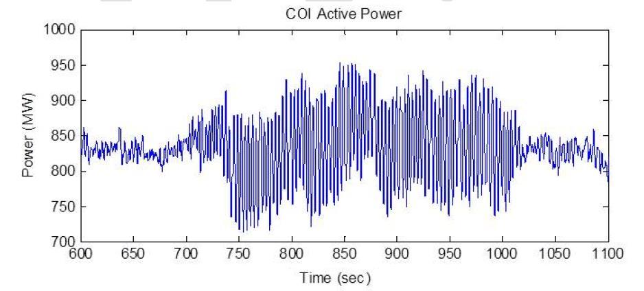
18 18 Examples h=0.34>0.11 Forced oscillation WECC FO, 2015 From Dan


19 19 2. Features of Start Up Waveform Different intrinsic system dampings result in different features of start up waveform Start up: the stage when the amplitude increases
20 20 Features of Start Up Waveform The envelope of start up waveform Ae t B Natural oscillation A 0, B 0, 0 Forced oscillation A 0, B A, 0
21 21 Features of Start Up Waveform The envelope of start up waveform the difference is σ Steps Peak-peak value increment of peak-peak value logarithm X i Linear fitting to get the slope Ae S>ε: natural oscillation, S<-ε: forced oscillation t B Yi X i X i 1 A(e 1)e T Z ln Y (ln( A(e 1)) T )+ T i i i S T T ( i 1) T

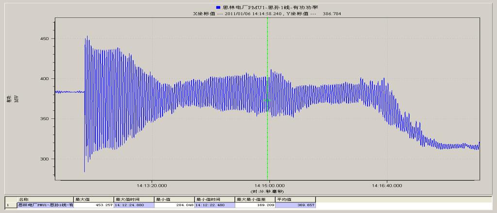
22 22 Examples Measured S=0.14>0, Natural Simulated S=-0.06<0, Forced
23 23 3. Spectral Methods (From Ruichao and Dan) The actual system response contains three components The intrinsic damping is contained in the ambient component
24 24 Natural (undamped) Steady State Response y r t = 2 c r u n v n x 0 cos ω n t + c r u n v n x 0 Transient M + l=1 q l t 2 c r u n v n b 2l cos ω n t + c r u n v n b 2l M + l=1 q l t N i=1 i n,n c r u i v i b 2l e λ it Noise 1: Random Sinusoidal Noise Noise 2: Colored Noise Forced y r t = m=1 N c r u i v i b 1 e λ it A m cos mω 0 t + A m Forced i=1 M + q l t N c r u i v i b 2l e λ it Colored Noise l=1 i=1
25 25 Signal-Noise Separation First separate the whole response into signal and noise Power spectral density (PSD) of natural oscillation S yr y r ω n = S ysr y Sr ω n + S ynr y Nr ω n S xsr x Sr ω n = 2πc r u n v n x 0 2 δ 0 2 PSD of signal/transient component 2 2 S ynr y Nr ω n 2πc r u n v n b 2l Sql q l ω δ 0 2 l=1 For two different measurements M PSD of noise, dominated by sinusoidal noise ω n 2 α S = S y S1 y S1 = c 1u n S ys2 y S2 ω 2 α N = S y N1 y ω N1 n = c 1u n Equal n c 2 u S n yn2 y N2 ω 2 n c 2 u n 2
26 26 Signal-Noise Separation Power spectral density (PSD) of forced oscillation S yr y r ω 0 = S ysr y Sr ω 0 + S ynr y Nr ω 0 N 2πA1 c r u i v i b 1 S yrf y rf ω 0 = jω 0 λ i i=1 2 δ 0 2 PSD of signal/forced component M S yrn y rn ω 0 = l=1 N cr u i v i b 2l jω 0 λ i i=1 2 S ql q l ω 0 PSD of noise For two different measurements ω n α S = S y S1 y S1 α S ys2 y S2 ω N = S y N1 y N1 ω n NOT Equal n S yn2 y N2 ω n
27 27 Natural Examples α S = 3.80 and α N = 3.85 Forced α S = 7.28 and α N = 0.91 Hz Hz Hz Time (sec.) Time (sec.) Noise Response Transient Response Noise + Transient Response Gen 7 spd Time (sec.) Hz Hz Hz Noise Response Forced Response Noise + Forced Response Gen 7 spd Time (sec.) Time (sec.) Time (sec.) Hz Noise Response Gen 22 spd Hz Noise Response Gen 22 spd Hz Hz Time (sec.) Time (sec.) Transient Response Noise + Transient Response Time (sec.) Hz Hz Time (sec.) Time (sec.) Forced Response Noise + Forced Response Time (sec.)
28 28 Cross-Spectrum Difference Function To detect the existence of the random sinusoid component cross-spectrum difference function S r Ω Y rw1 Y rw2 Y rw2 Y rw3 Y rwi the scaled DFT of the signal over window i Cross-spectrum index E S r Ω S g Ω 2 C rg Ω E S r Ω S r Ω E S g Ω S g Ω r, g: different measurement channels Criterion C rg Ω = 1 C rg Ω < 1 Natural Forced
29 29 Examples Natural Forced Voltage amplitude (p.u) Voltage amplitude (p.u) Time (s) Time (s) Mean with Standard Deviation Mean with Standard Deviation Channel Channel
30 30 Examples An actual forced oscillation incident in the western North American power system C rg [ o ] Pair
31 Conclusions Some methods for online distinguishing natural and forced oscillations are proposed The problem is NOT well solved Due to the complexity of actual oscillation curves, many methods, though have solid theoretical foundations and perform well with simulation results, do not perform well with actual records More practical approaches are still needed
32 32 Thanks! Lei CHEN PhD, Associate Professor Department of Electrical Engineering Tsinghua University
Notes on the Periodically Forced Harmonic Oscillator
 Notes on the Periodically orced Harmonic Oscillator Warren Weckesser Math 38 - Differential Equations 1 The Periodically orced Harmonic Oscillator. By periodically forced harmonic oscillator, we mean the
MODULE I. Transient Response:
 Transient Response: MODULE I The Transient Response (also known as the Natural Response) is the way the circuit responds to energies stored in storage elements, such as capacitors and inductors. If a capacitor
To find the step response of an RC circuit
 To find the step response of an RC circuit v( t) v( ) [ v( t) v( )] e tt The time constant = RC The final capacitor voltage v() The initial capacitor voltage v(t ) To find the step response of an RL circuit
Modal Decomposition and the Time-Domain Response of Linear Systems 1
 MASSACHUSETTS INSTITUTE OF TECHNOLOGY DEPARTMENT OF MECHANICAL ENGINEERING.151 Advanced System Dynamics and Control Modal Decomposition and the Time-Domain Response of Linear Systems 1 In a previous handout
ECEN 667 Power System Stability Lecture 20: Oscillations, Small Signal Stability Analysis
 ECEN 667 Power System Stability Lecture 20: Oscillations, Small Signal Stability Analysis Prof. Tom Overbye Dept. of Electrical and Computer Engineering Texas A&M University, overbye@tamu.edu 1 Announcements
Sinusoidal Steady-State Analysis
 Sinusoidal Steady-State Analysis Almost all electrical systems, whether signal or power, operate with alternating currents and voltages. We have seen that when any circuit is disturbed (switched on or
Vibration Testing. an excitation source a device to measure the response a digital signal processor to analyze the system response
 Vibration Testing For vibration testing, you need an excitation source a device to measure the response a digital signal processor to analyze the system response i) Excitation sources Typically either
Chapter 8: Frequency Domain Analysis
 Chapter 8: Frequency Domain Analysis Samantha Ramirez Preview Questions 1. What is the steady-state response of a linear system excited by a cyclic or oscillatory input? 2. How does one characterize the
(b) A unity feedback system is characterized by the transfer function. Design a suitable compensator to meet the following specifications:
 A unity feedback system is characterized by the transfer function. Design a suitable compensator to meet the following specifications:") 1. (a) The open loop transfer function of a unity feedback control system is given by G(S) = K/S(1+0.1S)(1+S) (i) Determine the value of K so that the resonance peak M r of the system is equal to 1.4.
1. (a) The open loop transfer function of a unity feedback control system is given by G(S) = K/S(1+0.1S)(1+S) (i) Determine the value of K so that the resonance peak M r of the system is equal to 1.4.
ECE Circuit Theory. Final Examination. December 5, 2008
 ECE 212 H1F Pg 1 of 12 ECE 212 - Circuit Theory Final Examination December 5, 2008 1. Policy: closed book, calculators allowed. Show all work. 2. Work in the provided space. 3. The exam has 3 problems
Section 4.9; Section 5.6. June 30, Free Mechanical Vibrations/Couple Mass-Spring System
 Section 4.9; Section 5.6 Free Mechanical Vibrations/Couple Mass-Spring System June 30, 2009 Today s Session Today s Session A Summary of This Session: Today s Session A Summary of This Session: (1) Free
Forced Mechanical Vibrations
 Forced Mechanical Vibrations Today we use methods for solving nonhomogeneous second order linear differential equations to study the behavior of mechanical systems.. Forcing: Transient and Steady State
ME 563 HOMEWORK # 7 SOLUTIONS Fall 2010
 ME 563 HOMEWORK # 7 SOLUTIONS Fall 2010 PROBLEM 1: Given the mass matrix and two undamped natural frequencies for a general two degree-of-freedom system with a symmetric stiffness matrix, find the stiffness
Math Assignment 5
 Math 2280 - Assignment 5 Dylan Zwick Fall 2013 Section 3.4-1, 5, 18, 21 Section 3.5-1, 11, 23, 28, 35, 47, 56 Section 3.6-1, 2, 9, 17, 24 1 Section 3.4 - Mechanical Vibrations 3.4.1 - Determine the period
4.2 Homogeneous Linear Equations
 4.2 Homogeneous Linear Equations Homogeneous Linear Equations with Constant Coefficients Consider the first-order linear differential equation with constant coefficients a 0 and b. If f(t) = 0 then this
Chapter 3 Mathematical Methods
 Chapter 3 Mathematical Methods Slides to accompany lectures in Vibro-Acoustic Design in Mechanical Systems 0 by D. W. Herrin Department of Mechanical Engineering Lexington, KY 40506-0503 Tel: 859-8-0609
EXPERIMENT 07 TO STUDY DC RC CIRCUIT AND TRANSIENT PHENOMENA
 EXPERIMENT 07 TO STUDY DC RC CIRCUIT AND TRANSIENT PHENOMENA DISCUSSION The capacitor is a element which stores electric energy by charging the charge on it. Bear in mind that the charge on a capacitor
ANNEX A: ANALYSIS METHODOLOGIES
 ANNEX A: ANALYSIS METHODOLOGIES A.1 Introduction Before discussing supplemental damping devices, this annex provides a brief review of the seismic analysis methods used in the optimization algorithms considered
Distributed Real-Time Electric Power Grid Event Detection and Dynamic Characterization
 Distributed Real-Time Electric Power Grid Event Detection and Dynamic Characterization Raymond de Callafon, Charles H. Wells University of California, San Diego & OSIsoft CIGRE Grid of the Future Symposium,
Power system modelling under the phasor approximation
 ELEC0047 - Power system dynamics, control and stability Thierry Van Cutsem t.vancutsem@ulg.ac.be www.montefiore.ulg.ac.be/~vct October 2018 1 / 16 Electromagnetic transient vs. phasor-mode simulations
The Energy Flow Approach for Oscillation Source Location and Damping Evaluation
 1 The Energy Flow Approach for Oscillation Source Location an Damping Evaluation Lei CHEN PhD, Associate Professor Department of Electrical Engineering Tsinghua University chenlei08@tsinghua.eu.cn Backgroun
ω 0 = 2π/T 0 is called the fundamental angular frequency and ω 2 = 2ω 0 is called the
 he ime-frequency Concept []. Review of Fourier Series Consider the following set of time functions {3A sin t, A sin t}. We can represent these functions in different ways by plotting the amplitude versus
Source-Free RC Circuit
 First Order Circuits Source-Free RC Circuit Initial charge on capacitor q = Cv(0) so that voltage at time 0 is v(0). What is v(t)? Prof Carruthers (ECE @ BU) EK307 Notes Summer 2018 150 / 264 First Order
Raktim Bhattacharya. . AERO 632: Design of Advance Flight Control System. Preliminaries
 . AERO 632: of Advance Flight Control System. Preliminaries Raktim Bhattacharya Laboratory For Uncertainty Quantification Aerospace Engineering, Texas A&M University. Preliminaries Signals & Systems Laplace
Introduction to Vibration. Professor Mike Brennan
 Introduction to Vibration Professor Mie Brennan Introduction to Vibration Nature of vibration of mechanical systems Free and forced vibrations Frequency response functions Fundamentals For free vibration
2. Determine whether the following pair of functions are linearly dependent, or linearly independent:
 Topics to be covered on the exam include: Recognizing, and verifying solutions to homogeneous second-order linear differential equations, and their corresponding Initial Value Problems Recognizing and
ECE 585 Power System Stability
 Homework 1, Due on January 29 ECE 585 Power System Stability Consider the power system below. The network frequency is 60 Hz. At the pre-fault steady state (a) the power generated by the machine is 400
1 Phasors and Alternating Currents
 Physics 4 Chapter : Alternating Current 0/5 Phasors and Alternating Currents alternating current: current that varies sinusoidally with time ac source: any device that supplies a sinusoidally varying potential
Dynamic Phasors in Modeling, Analysis and Control of Energy Processing Systems
 Dynamic Phasors in Modeling, Analysis and Control of Energy Processing Systems 6/20/02 Alex M. Stanković Northeastern University, Boston, MA 1 Research Program Overview My research program focuses on the
Laboratory notes. Torsional Vibration Absorber
 Titurus, Marsico & Wagg Torsional Vibration Absorber UoB/1-11, v1. Laboratory notes Torsional Vibration Absorber Contents 1 Objectives... Apparatus... 3 Theory... 3 3.1 Background information... 3 3. Undamped
Geotechnical Earthquake Engineering
 Geotechnical Earthquake Engineering by Dr. Deepankar Choudhury Professor Department of Civil Engineering IIT Bombay, Powai, Mumbai 400 076, India. Email: dc@civil.iitb.ac.in URL: http://www.civil.iitb.ac.in/~dc/
Ordinary differential equations
 Class 7 Today s topics The nonhomogeneous equation Resonance u + pu + qu = g(t). The nonhomogeneous second order linear equation This is the nonhomogeneous second order linear equation u + pu + qu = g(t).
SCHOOL OF ELECTRICAL, MECHANICAL AND MECHATRONIC SYSTEMS. Transient Stability LECTURE NOTES SPRING SEMESTER, 2008
 SCHOOL OF ELECTRICAL, MECHANICAL AND MECHATRONIC SYSTEMS LECTURE NOTES Transient Stability SPRING SEMESTER, 008 October 7, 008 Transient Stability Transient stability refers to the ability of a synchronous
Control Systems, Lecture04
 Control Systems, Lecture04 İbrahim Beklan Küçükdemiral Yıldız Teknik Üniversitesi 2015 1 / 53 Transfer Functions The output response of a system is the sum of two responses: the forced response and the
2.3 Oscillation. The harmonic oscillator equation is the differential equation. d 2 y dt 2 r y (r > 0). Its solutions have the form
. Its solutions have the form") 2. Oscillation So far, we have used differential equations to describe functions that grow or decay over time. The next most common behavior for a function is to oscillate, meaning that it increases and
2. Oscillation So far, we have used differential equations to describe functions that grow or decay over time. The next most common behavior for a function is to oscillate, meaning that it increases and
Physics 401, Spring 2016 Eugene V. Colla
 Physics 41, Spring 16 Eugene V. Colla.8 (rad). -.8 1 3 4 5 6 7 8 time (s) 1.Driven torsional oscillator. Equations.Setup. Kinematics 3.Resonance 4.Beats 5.Nonlinear effects 6.Comments 3/7/16 3/7/16 3 Tacoma
Note 11: Alternating Current (AC) Circuits
 Circuits") Note 11: Alternating Current (AC) Circuits V R No phase difference between the voltage difference and the current and max For alternating voltage Vmax sin t, the resistor current is ir sin t. the instantaneous
Note 11: Alternating Current (AC) Circuits V R No phase difference between the voltage difference and the current and max For alternating voltage Vmax sin t, the resistor current is ir sin t. the instantaneous
Chapter 31: RLC Circuits. PHY2049: Chapter 31 1
 hapter 31: RL ircuits PHY049: hapter 31 1 L Oscillations onservation of energy Topics Damped oscillations in RL circuits Energy loss A current RMS quantities Forced oscillations Resistance, reactance,
Chapter 23: Principles of Passive Vibration Control: Design of absorber
 Chapter 23: Principles of Passive Vibration Control: Design of absorber INTRODUCTION The term 'vibration absorber' is used for passive devices attached to the vibrating structure. Such devices are made
School of Mechanical Engineering Purdue University. ME375 Dynamic Response - 1
 Dynamic Response of Linear Systems Linear System Response Superposition Principle Responses to Specific Inputs Dynamic Response of f1 1st to Order Systems Characteristic Equation - Free Response Stable
Control Systems I Lecture 10: System Specifications
 Control Systems I Lecture 10: System Specifications Readings: Guzzella, Chapter 10 Emilio Frazzoli Institute for Dynamic Systems and Control D-MAVT ETH Zürich November 24, 2017 E. Frazzoli (ETH) Lecture
Central to this is two linear transformations: the Fourier Transform and the Laplace Transform. Both will be considered in later lectures.
 In this second lecture, I will be considering signals from the frequency perspective. This is a complementary view of signals, that in the frequency domain, and is fundamental to the subject of signal
Chapter 33. Alternating Current Circuits
 Chapter 33 Alternating Current Circuits 1 Capacitor Resistor + Q = C V = I R R I + + Inductance d I Vab = L dt AC power source The AC power source provides an alternative voltage, Notation - Lower case
Sinusoidal Modeling. Yannis Stylianou SPCC University of Crete, Computer Science Dept., Greece,
 Sinusoidal Modeling Yannis Stylianou University of Crete, Computer Science Dept., Greece, yannis@csd.uoc.gr SPCC 2016 1 Speech Production 2 Modulators 3 Sinusoidal Modeling Sinusoidal Models Voiced Speech
M A : Ordinary Differential Equations
 M A 2 0 5 1: Ordinary Differential Equations Essential Class Notes & Graphics D 19 * 2018-2019 Sections D07 D11 & D14 1 1. INTRODUCTION CLASS 1 ODE: Course s Overarching Functions An introduction to the
Transient Stability Analysis with PowerWorld Simulator
 Transient Stability Analysis with PowerWorld Simulator T11: Single Machine Infinite Bus Modeling (SMIB) 21 South First Street Champaign, Illinois 6182 +1 (217) 384.633 support@powerworld.com http://www.powerworld.com
Equivalent Circuits with Multiple Damper Windings (e.g. Round rotor Machines)
") Equivalent Circuits with Multiple Damper Windings (e.g. Round rotor Machines) d axis: L fd L F - M R fd F L 1d L D - M R 1d D R fd R F e fd e F R 1d R D Subscript Notations: ( ) fd ~ field winding quantities
Equivalent Circuits with Multiple Damper Windings (e.g. Round rotor Machines) d axis: L fd L F - M R fd F L 1d L D - M R 1d D R fd R F e fd e F R 1d R D Subscript Notations: ( ) fd ~ field winding quantities
ME scope Application Note 28
 App Note 8 www.vibetech.com 3/7/17 ME scope Application Note 8 Mathematics of a Mass-Spring-Damper System INTRODUCTION In this note, the capabilities of ME scope will be used to build a model of the mass-spring-damper
Sinusoidal Steady-State Analysis
 Chapter 4 Sinusoidal Steady-State Analysis In this unit, we consider circuits in which the sources are sinusoidal in nature. The review section of this unit covers most of section 9.1 9.9 of the text.
Input-Output Peak Picking Modal Identification & Output only Modal Identification and Damage Detection of Structures using
 Input-Output Peak Picking Modal Identification & Output only Modal Identification and Damage Detection of Structures using Time Frequency and Wavelet Techniquesc Satish Nagarajaiah Professor of Civil and
Laboratory handout 5 Mode shapes and resonance
 laboratory handouts, me 34 82 Laboratory handout 5 Mode shapes and resonance In this handout, material and assignments marked as optional can be skipped when preparing for the lab, but may provide a useful
Chapter a. Spring constant, k : The change in the force per unit length change of the spring. b. Coefficient of subgrade reaction, k:
 Principles of Soil Dynamics 3rd Edition Das SOLUTIONS MANUAL Full clear download (no formatting errors) at: https://testbankreal.com/download/principles-soil-dynamics-3rd-editiondas-solutions-manual/ Chapter
Iterative Controller Tuning Using Bode s Integrals
 Iterative Controller Tuning Using Bode s Integrals A. Karimi, D. Garcia and R. Longchamp Laboratoire d automatique, École Polytechnique Fédérale de Lausanne (EPFL), 05 Lausanne, Switzerland. email: alireza.karimi@epfl.ch
Frequency Resolution Effects on FRF Estimation: Cyclic Averaging vs. Large Block Size
 Frequency Resolution Effects on FRF Estimation: Cyclic Averaging vs. Large Block Size Allyn W. Phillips, PhD Andrew. Zucker Randall J. Allemang, PhD Research Assistant Professor Research Assistant Professor
Dynamic circuits: Frequency domain analysis
 Electronic Circuits 1 Dynamic circuits: Contents Free oscillation and natural frequency Transfer functions Frequency response Bode plots 1 System behaviour: overview 2 System behaviour : review solution
SPERIMENTAZIONE DI STRUTTURE AEROSPAZIALI TESTING OF AEROSPACE STRUCTURES
 SPERIMENTAZIONE DI STRUTTURE AEROSPAZIALI TESTING OF AEROSPACE STRUCTURES Giuliano Coppotelli c aa 2014/2015 Versione aggiornata al 24 Settembre 2014 Trascrizione e figure a cura di Roberta Cumbo Indice
Environmental Effects and Control of Noise Lecture 2
 Noise, Vibration, Harshness Sound Quality Research Group NVH-SQ Group University of Windsor 92-455 Environmental Effects and Control of Noise Copyright 2015 Colin Novak Copyright 2015 by Colin Novak. All
Differential Equations 2280 Sample Midterm Exam 3 with Solutions Exam Date: 24 April 2015 at 12:50pm
 Differential Equations 228 Sample Midterm Exam 3 with Solutions Exam Date: 24 April 25 at 2:5pm Instructions: This in-class exam is 5 minutes. No calculators, notes, tables or books. No answer check is
CHAPTER 14 SIGNAL GENERATORS AND WAVEFORM SHAPING CIRCUITS
 CHAPTER 4 SIGNA GENERATORS AND WAEFORM SHAPING CIRCUITS Chapter Outline 4. Basic Principles of Sinusoidal Oscillators 4. Op Amp RC Oscillators 4.3 C and Crystal Oscillators 4.4 Bistable Multivibrators
Second order linear equations
 Second order linear equations Samy Tindel Purdue University Differential equations - MA 266 Taken from Elementary differential equations by Boyce and DiPrima Samy T. Second order equations Differential
Fall 2011 ME 2305 Network Analysis. Sinusoidal Steady State Analysis of RLC Circuits
 Fall 2011 ME 2305 Network Analysis Chapter 4 Sinusoidal Steady State Analysis of RLC Circuits Engr. Humera Rafique Assistant Professor humera.rafique@szabist.edu.pk Faculty of Engineering (Mechatronics)
IEEE PES Task Force on Benchmark Systems for Stability Controls
 IEEE PES Task Force on Benchmark Systems for Stability Controls Report on Benchmark #2 The Brazilian 7 Bus (Equivalent Model) Version 1 - October 23 rd, 214 Fernando J. de Marco, Leonardo Lima and Nelson
ENGI Second Order Linear ODEs Page Second Order Linear Ordinary Differential Equations
 ENGI 344 - Second Order Linear ODEs age -01. Second Order Linear Ordinary Differential Equations The general second order linear ordinary differential equation is of the form d y dy x Q x y Rx dx dx Of
Systems Analysis and Control
 Systems Analysis and Control Matthew M. Peet Illinois Institute of Technology Lecture 8: Response Characteristics Overview In this Lecture, you will learn: Characteristics of the Response Stability Real
Unit Trip April 20, 2011, 13:40:53 CDT. McDonald Angle Relative to U.T. Austin Second
 _35_EE394J_Spring11 Order_Illustrator.doc Ringdown Analysis of Voltage Phase Angle Using 30 Point-per- Synchrophasor Data and the Excel Solver 52.5 57.75.19 52.95 0.95-1.19 53.30 2.28 1.84 0.544 0.127
Sinusoidal Response of RLC Circuits
 Sinusoidal Response of RLC Circuits Series RL circuit Series RC circuit Series RLC circuit Parallel RL circuit Parallel RC circuit R-L Series Circuit R-L Series Circuit R-L Series Circuit Instantaneous
School of Mechanical Engineering Purdue University
 Case Study ME375 Frequency Response - 1 Case Study SUPPORT POWER WIRE DROPPERS Electric train derives power through a pantograph, which contacts the power wire, which is suspended from a catenary. During
1845. A novel approach for the evaluation of frequency-band loss factor based on last decay rate of vibrational amplitude
 1845. A novel approach for the evaluation of frequency-band loss factor based on last decay rate of vibrational amplitude Jintao Gu 1, Meiping Sheng 2, Zhiwei Guo 3, Hanbei Guo 4 School of Marine Science
15 n=0. zz = re jθ re jθ = r 2. (b) For division and multiplication, it is handy to use the polar representation: z = rejθ. = z 1z 2.
 For division and multiplication, it is handy to use the polar representation: z = rejθ. = z 1z 2.") Professor Fearing EECS0/Problem Set v.0 Fall 06 Due at 4 pm, Fri. Sep. in HW box under stairs (st floor Cory) Reading: EE6AB notes. This problem set should be review of material from EE6AB. (Please note,
Professor Fearing EECS0/Problem Set v.0 Fall 06 Due at 4 pm, Fri. Sep. in HW box under stairs (st floor Cory) Reading: EE6AB notes. This problem set should be review of material from EE6AB. (Please note,
M A : Ordinary Differential Equations
 M A 2 0 5 1: Ordinary Differential Equations Essential Class Notes & Graphics C 17 * Sections C11-C18, C20 2016-2017 1 Required Background 1. INTRODUCTION CLASS 1 The definition of the derivative, Derivative
Vibration Testing. Typically either instrumented hammers or shakers are used.
 Vibration Testing Vibration Testing Equipment For vibration testing, you need an excitation source a device to measure the response a digital signal processor to analyze the system response Excitation
Estimation of electromechanical modes in power systems using system identification techniques
 Estimation of electromechanical modes in power systems using system identification techniques Vedran S. Peric, Luigi Vanfretti, X. Bombois E-mail: vperic@kth.se, luigiv@kth.se, xavier.bombois@ec-lyon.fr
ANALYSIS OF SUBSYNCHRONOUS RESONANCE EFFECT IN SERIES COMPENSATED LINE WITH BOOSTER TRANSFORMER
 ANALYSIS OF SUBSYNCHRONOUS RESONANCE EFFECT IN SERIES COMPENSATED LINE WITH BOOSTER TRANSFORMER G.V.RAJASEKHAR, 2 GVSSNS SARMA,2 Department of Electrical Engineering, Aurora Engineering College, Hyderabad,
Waveform Parameters. Correlation of Count Rate and Material Properties. Emission Hits and Count. Acoustic Emission Event Energy
 Cumulative representations of these parameters can be defined as a function of time or test parameter (such as pressure or temperature), including: () total hits, (2) amplitude distribution and (3) accumulated
Using a TCSC for Line Power Scheduling and System Oscillation Damping Small Signal and Transient Stability Studies
 Using a TCSC for Line Power Scheduling and System Oscillation Damping Small Signal and Transient Stability Studies Nelson Martins - CEPEL Herminio Pinto - CEPEL John J. Paserba - Mitsubishi Electric Products,
DOING PHYSICS WITH MATLAB
 DOING PHYSIS WITH MATAB THE FINITE DIFFERENE METHOD FOR THE NUMERIA ANAYSIS OF IRUITS ONTAINING RESISTORS, APAITORS AND INDUTORS MATAB DOWNOAD DIRETORY N01.m Voltage and current for a resistor, capacitor
CMPT 318: Lecture 5 Complex Exponentials, Spectrum Representation
 CMPT 318: Lecture 5 Complex Exponentials, Spectrum Representation Tamara Smyth, tamaras@cs.sfu.ca School of Computing Science, Simon Fraser University January 23, 2006 1 Exponentials The exponential is
Q. 1 Q. 25 carry one mark each.
 Q. Q. 5 carry one mark each. Q. Consider a system of linear equations: x y 3z =, x 3y 4z =, and x 4y 6 z = k. The value of k for which the system has infinitely many solutions is. Q. A function 3 = is
2.010 Fall 2000 Solution of Homework Assignment 1
 2. Fall 2 Solution of Homework Assignment. Compact Disk Player. This is essentially a reprise of Problems and 2 from the Fall 999 2.3 Homework Assignment 7. t is included here to encourage you to review
Introduction to Vibration. Mike Brennan UNESP, Ilha Solteira São Paulo Brazil
 Introduction to Vibration Mike Brennan UNESP, Ilha Solteira São Paulo Brazil Vibration Most vibrations are undesirable, but there are many instances where vibrations are useful Ultrasonic (very high
Applications of Second-Order Linear Differential Equations
 CHAPTER 14 Applications of Second-Order Linear Differential Equations SPRING PROBLEMS The simple spring system shown in Fig. 14-! consists of a mass m attached lo the lower end of a spring that is itself
EE 230 Lecture 24. Waveform Generators. - Sinusoidal Oscillators
 EE 230 Lecture 24 Waveform Generators - Sinusoidal Oscillators Quiz 18 Determine the characteristic equation for the following network without adding an excitation. C R L And the number is? 1 3 8 2? 6
Sinusoidal steady-state analysis
 Sinusoidal steady-state analysis From our previous efforts with AC circuits, some patterns in the analysis started to appear. 1. In each case, the steady-state voltages or currents created in response
Driven Harmonic Oscillator
 Driven Harmonic Oscillator Physics 6B Lab Experiment 1 APPARATUS Computer and interface Mechanical vibrator and spring holder Stands, etc. to hold vibrator Motion sensor C-209 spring Weight holder and
IEEE TRANSACTIONS ON SMART GRID, VOL. 10, NO. 1, JANUARY
 IEEE TRANSACTIONS ON SMART GRID, VOL. 10, NO. 1, JANUARY 2019 493 A Forecasting-Residual Spectrum Analysis Method for Distinguishing Forced and Natural Oscillations Mohammadreza Ghorbaniparvar, Student
NORMAL MODES, WAVE MOTION AND THE WAVE EQUATION. Professor G.G.Ross. Oxford University Hilary Term 2009
 NORMAL MODES, WAVE MOTION AND THE WAVE EQUATION Professor G.G.Ross Oxford University Hilary Term 009 This course of twelve lectures covers material for the paper CP4: Differential Equations, Waves and
Modeling and Experimentation: Mass-Spring-Damper System Dynamics
 Modeling and Experimentation: Mass-Spring-Damper System Dynamics Prof. R.G. Longoria Department of Mechanical Engineering The University of Texas at Austin July 20, 2014 Overview 1 This lab is meant to
Radar Dish. Armature controlled dc motor. Inside. θ r input. Outside. θ D output. θ m. Gearbox. Control Transmitter. Control. θ D.
 Radar Dish ME 304 CONTROL SYSTEMS Mechanical Engineering Department, Middle East Technical University Armature controlled dc motor Outside θ D output Inside θ r input r θ m Gearbox Control Transmitter
CONTRIBUTION TO THE IDENTIFICATION OF THE DYNAMIC BEHAVIOUR OF FLOATING HARBOUR SYSTEMS USING FREQUENCY DOMAIN DECOMPOSITION
 CONTRIBUTION TO THE IDENTIFICATION OF THE DYNAMIC BEHAVIOUR OF FLOATING HARBOUR SYSTEMS USING FREQUENCY DOMAIN DECOMPOSITION S. Uhlenbrock, University of Rostock, Germany G. Schlottmann, University of
AC analysis. EE 201 AC analysis 1
 AC analysis Now we turn to circuits with sinusoidal sources. Earlier, we had a brief look at sinusoids, but now we will add in capacitors and inductors, making the story much more interesting. What are
ODE. Philippe Rukimbira. Department of Mathematics Florida International University PR (FIU) MAP / 92
 MAP / 92") ODE Philippe Rukimbira Department of Mathematics Florida International University PR (FIU) MAP 2302 1 / 92 4.4 The method of Variation of parameters 1. Second order differential equations (Normalized,
ODE Philippe Rukimbira Department of Mathematics Florida International University PR (FIU) MAP 2302 1 / 92 4.4 The method of Variation of parameters 1. Second order differential equations (Normalized,
Fourier Analysis of Signals Using the DFT
 Fourier Analysis of Signals Using the DFT ECE 535 Lecture April 29, 23 Overview: Motivation Many applications require analyzing the frequency content of signals Speech processing study resonances of vocal
The particular integral :
 Second order linear equation with constant coefficients The particular integral : d f df Lf = a + a + af = h( x) Solutions with combinations of driving functions d f df Lf = a + a + af = h( x) + h( x)
SHAKING TABLE DEMONSTRATION OF DYNAMIC RESPONSE OF BASE-ISOLATED BUILDINGS ***** Instructor Manual *****
 SHAKING TABLE DEMONSTRATION OF DYNAMIC RESPONSE OF BASE-ISOLATED BUILDINGS ***** Instructor Manual ***** A PROJECT DEVELOPED FOR THE UNIVERSITY CONSORTIUM ON INSTRUCTIONAL SHAKE TABLES http://wusceel.cive.wustl.edu/ucist/
EA2.3 - Electronics 2 1
 In the previous lecture, I talked about the idea of complex frequency s, where s = σ + jω. Using such concept of complex frequency allows us to analyse signals and systems with better generality. In this
VALLIAMMAI ENGINEERING COLLEGE SRM Nagar, Kattankulathur
 VALLIAMMAI ENGINEERING COLLEGE SRM Nagar, Kattankulathur 603 203. DEPARTMENT OF ELECTRONICS & COMMUNICATION ENGINEERING SUBJECT QUESTION BANK : EC6405 CONTROL SYSTEM ENGINEERING SEM / YEAR: IV / II year
Circuits with Capacitor and Inductor
 Circuits with Capacitor and Inductor We have discussed so far circuits only with resistors. While analyzing it, we came across with the set of algebraic equations. Hereafter we will analyze circuits with
IC6501 CONTROL SYSTEMS
 DHANALAKSHMI COLLEGE OF ENGINEERING CHENNAI DEPARTMENT OF ELECTRICAL AND ELECTRONICS ENGINEERING YEAR/SEMESTER: II/IV IC6501 CONTROL SYSTEMS UNIT I SYSTEMS AND THEIR REPRESENTATION 1. What is the mathematical
5 questions, 3 points each, 15 points total possible. 26 Fe Cu Ni Co Pd Ag Ru 101.
 Physical Chemistry II Lab CHEM 4644 spring 2017 final exam KEY 5 questions, 3 points each, 15 points total possible h = 6.626 10-34 J s c = 3.00 10 8 m/s 1 GHz = 10 9 s -1. B= h 8π 2 I ν= 1 2 π k μ 6 P
Refinements to Incremental Transistor Model
 Refinements to Incremental Transistor Model This section presents modifications to the incremental models that account for non-ideal transistor behavior Incremental output port resistance Incremental changes