X-band high-gradient and CLIC R&D for future colliders
|
|
|
- Rosaline Stone
- 5 years ago
- Views:
Transcription


1 Talk outline The work plan issues, organization & timescale Recent R&D results High-gradient structures CTF3 Other R&D activities Beam physics Technical issues Conclusion X-band high-gradient and CLIC R&D for future colliders R. Corsini CERN for the CLIC/CTF3 Collaboration
2 Aim of the CLIC study: develop technology for e-/e+ linear collider with the requirements: E CM should cover range from ILC to LHC maximum reach and beyond E CM = TeV, L > few cm -2 with acceptable background and energy spread Design compatible with maximum length ~ 50 km Affordable Total power consumption < 500 MW Physics motivation: "Physics at the CLIC Multi-TeV Linear Collider: report of the CLIC Physics Working Group, CERN report Present goal: Demonstrate all key feasibility issues and document in a CDR by 2010
 Gazi Universities (Turkey) IRFU/Saclay (France) Helsinki Institute of Physics (Finland) JINR")
 INFN / LNF (Italy) LAPP/ESIA (France) EPAC 2008 CLIC / CTF3 G.Geschonke, CERN J.")
 Oslo University (Norway) PSI (Switzerland), Polytech.")
3 The CTF3 CLIC world wide collaboration Ankara University (Turkey) BINP (Russia) CERN CIEMAT (Spain) Cockcroft Institute (UK) Gazi Universities (Turkey) IRFU/Saclay (France) Helsinki Institute of Physics (Finland) JINR (Russia) IAP (Russia) JLAB (USA) IAP NASU (Ukraine) KEK (Japan) Instituto de Fisica Corpuscular (Spain) LAL/Orsay (France) INFN / LNF (Italy) LAPP/ESIA (France) EPAC 2008 CLIC / CTF3 G.Geschonke, CERN J.Adams Institute, (UK) NCP (Pakistan) North-West. Univ. Illinois (USA) Oslo University (Norway) PSI (Switzerland), Polytech. University of Catalonia (Spain) RRCAT-Indore (India) Royal Holloway, Univ. London, (UK) SLAC (USA) 3 Uppsala University (Sweden)
4 CLIC/CTF3 Collaboration 27 institutes involving 17 funding agencies from 15 countries Organized as a HEP Detector Collaboration Started as CTF3, recently extended to CLIC R&D in view of CDR and beyond CLIC / ILC Collaboration Focusing on subjects with strong synergy between CLIC & ILC Making the best use of the available resources Identifying and understanding the differences due to technology and energy (technical, cost.) Preparing together the future evaluation of the two technologies by the Linear Collider Community made up of CLIC & ILC experts
5 CLIC organizational chart CLIC/CTF3 Collab. Board M.Calvetti/LNF CLIC Advisory Committee T.Raubenheimer/SLAC CLIC Steering Committee J.P.Delahaye Conceptual Design Report Editorial Board H.Schmickler CLIC Design J.P.Delahaye CLIC Physics & Detectors L.Linssen & D.Schlatter CTF3 project G.Geschonke
6 Work Plan until 2010: Demonstrate feasibility of CLIC technology (R&D on critical feasibility issues) Design of a linear Collider based on CLIC technology Estimation of its cost (capital investment & operation) CLIC Physics study and detector development Conceptual Design Report to be published in 2010 including: Physics, Accelerator and Detectors Results of feasibility study Preliminary performance and cost estimation R&D Issues classified in three categories: critical for feasibility critical for performance critical for cost fully addressed by specific R&D to be completed before 2010 results in CDR being addressed now by specific R&D to be completed before 2015 first assessments in CDR results in Technical Design Report (TDR) with consolidated performance & cost
7 Tentative long-term CLIC scenario Shortest, Success Oriented, Technically Limited Schedule Technology evaluation and Physics assessment based on LHC results for a possible decision on Linear Collider with staged construction starting with the lowest energy required by Physics R&D on Feasibility Issues Conceptual Design R&D on Performance and Cost issues Technical design Engineering Optimisation&Industrialisation Construction (in stages) Construction Detector Conceptual Design Report (CDR) Technical Design Report (TDR) Project approval? First Beam?
8 CLIC Parameters and upgrade scenario Luminosity (cm-2 sec-1) 1.E+35 1.E+34 2nd phase: luminosity increase 500 GeV nominal parameters ILC 1 st phase: Initial operation 500 GeV conservative parameters CLIC nominal CLIC conservative 4th phase: luminosity increase 3 TeV nominal parameters 3rd phase: 0.5 to 3 TeV energy upgrade 3 TeV conservative parameters 1.E Energy (TeV)
9 CLIC Parameter Table X-band high-gradient and CLIC R&D for future colliders Center-of-mass energy CLIC 500 GeV CLIC 3 TeV Beam parameters Accelerating structure Total (Peak 1%) luminosity Repetition rate (Hz) Loaded accel. gradient MV/m Main linac RF frequency GHz Bunch charge10 9 Bunch separation (ns) Beam pulse duration (ns) Beam power/beam MWatts Hor./vert. norm. emitt (10-6 /10-9 ) Hor/Vert FF focusing β* (mm) Hor./vert. IP beam size (nm) Hadronic events/crossing at IP Coherent pairs at IP BDS length (km) Total site length km Wall plug to beam transfert eff Total power consumption MW Conservative (0.6) /40 10/ / % Nominal Conservative Nominal 2.3 (1.4) G 2.7 (1.3) (2.0) /25 2.4/ /20 8 / / / / / % 415

10 What matters in a linear collider? Energy reach E cm = F fill L linac G acc High gradient Luminosity Acceleration efficiency Generation of small emittance Conservation of small emittance Extremely small beam spot at Interaction Point damping rings wake-fields, alignment, stability beam delivery system, stability
11 The small emittance challenge
12 The small beam size challenge 1000 SLC Vertical Beam Size (nm) CLIC 3 TeV FFTB CLIC 500 GeV ATF2 ILC GeV Horizontal Beam Size (nm)
 Compact collider - overall length @ 3 TeV <")
 Two-Beam Acceleration Scheme Drive beam - 100 A, 240 ns from 2.")

13 The CLIC way to a multi-tev linear collider - Basic features High acceleration gradient (100 MV/m) Compact collider - overall 3 TeV < 50 km Normal conducting accelerating structures High acceleration frequency (12 GHz) Two-Beam Acceleration Scheme Drive beam A, 240 ns from 2.4 GeV to 240 MeV Cost effective, reliable, efficient Simple tunnel, no active elements 140 MW Modular, easy energy upgrade in stages Main beam 1 A, 160 ns from 9 GeV to 1.5 TeV
14 CLIC Layout 3 TeV

15 CLIC Layout 500 GeV
 (SLAC, KEK, CERN, SACLAY + CTF3) Two Beam CTF3")
16 Table of CLIC feasibility issues High acceleration gradient RF power facilities (100 MV/m) (SLAC, KEK, CERN, SACLAY + CTF3) Two Beam CTF3 Scheme
 with optimum cost Calculate cost and performance (Luminosity/power) Total cost (a.u.) CLIC parameters Final choice of parameter is a compromise between cost, performance and other practical considerations A.")
17 CLIC accelerating structure optimization Luminosity / power Takes into account RF break-down limitations for peak surface field, power and pulse length Input from beam dynamics & beambeam effects at collision Based on parametric total cost model Find structure parameters (aperture, length, group velocity) with optimum cost Calculate cost and performance (Luminosity/power) Total cost (a.u.) CLIC parameters Final choice of parameter is a compromise between cost, performance and other practical considerations A. Grudiev et al. EPAC 06
 g /c")
18 CLIC accelerating structure requirements Loaded average accelerating gradient 100 MV/m Breakdown rate at nominal gradient per 3 TeV c.m. (1% luminosity loss) RF to beam efficiency in the 20 30% 3 TeV Long range wake at 2 nd bunch crossing W t, V/pC/mm/m E acc / N Structure Frequency: f [GHz] Average iris radius/wavelength: <a>/λ Input/Output iris radii: a 1,2 [mm] Input/Output iris thickness: d 1,2 [mm] Group velocity: v (1,2) g /c [%] N. of reg. cells, str. length: N c, l [mm] Bunch separation: N s [rf cycles] Luminosity per bunch X-ing: L b [m -2 ] Bunch population: N Number of bunches in a train: N b Filling time, rise time: τ f, τ r [ns] Pulse length: τ p [ns] Input power: P in [MW] P in /Ct P p 1/3 [MW/mm ns 1/3 ] Max. surface field: E max surf [MV/m] Max. temperature rise: ΔT max [K] Efficiency: η [%] Figure of merit: ηl b /N [a.u.] CLIC G , , , , ,

 Power Extraction & Transfer Structures (PETS)")


 Full Accelerator")
19 X-band high-gradient R&D - activities Structure construction (high precision machining, tolerances, material studies...) Power Extraction & Transfer Structures (PETS) development Development of high-power RF components Breakdown theory and simulation Basic physics experimental studies Single-cell and short constant impedance structures Waveguide breakdown experiments Pulsed-power heating experiments single-cell cavities (SLAC) Full Accelerator Structure Testing pulsed-power heating testing (SLAC)

20 X-band high-gradient R&D - collaborating Institutes CERN: Structure design & fabrication, high-power testing. SLAC: High-power testing, pulsed-surface-heating testing, test structure fabrication. KEK: Test structure fabrication and high-precision machining. High-power testing starting. Cockcroft Institute: Structure and beam dynamics simulations planned. PSI: Interest in structure design, breakdown theory and high-power testing. Helsinki Institute of Physics: Precision mechanical engineering. Breakdown simulation. Uppsala University: Two-beam test stand beam-lines, instrumentation and experiments. Breakdown experiments. CIEMAT: Test-PETS and RF components. Gycom/Nizhniy Novgorod: High-power RF components. Pakistan: Two-beam test stand hardware. Dubna: Pulsed surface heating experiment. DAPNIA, SACLAY: Superconducting-level cleaning. Planned test accelerating structure fabrication, wakefield monitor, highpower testing. US High-gradient collaboration: Many common subjects.

 Operational 11.")
 KEK Nextef X-band Klystron")

21 High-power RF facilities Testing of RF components: Accelerating structures PETS RF components SLAC NLCTA (3 RF stations) Klystron Lab (4 RF stations) Operational 11.4 GHz Up to ns CERN 12 GHz Test Stand (CEA-DAPNIA) KEK Nextef X-band Klystron Test Station Operational 11.4 GHz Up to ns Under construction start beginning GHz μs
.")

 40 35 30 25 20 15 10 5 ILC design 1.")
22 Structure T18_vg4.2 designed by CERN built at KEK, assembled and bonded in SLAC tested at SLAC (NLCTA). BKD Rate: 1/pulse/m RF BKD Rate vs. Gradient for 230ns Pulse CLIC 500 GeV CLIC 3 TeV requirements Unloaded Gradient: MV/m After 250hrs of RF conditioning After 500hrs After 900hrs After 1200hrs RF to beam Efficiency - temp stabilised (%) ILC design 1.3 GHz Pulsed SC SLC operation 3 GHz Single bunch NLC design 11.4 GHz CLIC design 3 TeV CLIC design 500 GeV T18vg GHz Loaded Average Accelerating Field (MV/m)


23 Next steps TD18 T18 tested 105 MV/m, 230 ns, 2x10⁻⁷ /(mxpulse) Supporting tests: Quadrant fabrication CD10 Choke mode CD10 Add damping Move to design iris range Move to design iris range and add damping CLIC G with damping full prototype Move to design iris range Add damping Supporting tests: C10 series T23 CLIC G undamped Today early 2009 late 2009
24 Drive Beam Accelerator efficient acceleration in fully loaded linac Delay loop 2 gap creation, pulse compression & frequency multiplication Transverse RF Deflectors Combiner ring 3 Combiner ring 4 pulse compression & frequency multiplication pulse compression & frequency multiplication Drive beam generation Drive Beam Decelerator Sector (24 in total) Power Extraction Drive beam time structure - initial Drive beam time structure - final 240 ns 240 ns 5.8 μs 140 μs total length sub-pulses A 2.4 GeV - 60 cm between bunches 24 pulses 100 A 2.5 cm between bunches

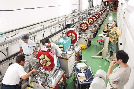
25 CTF3 Layout 4 A 1.2 μs 150 Mev DRIVE BEAM LINAC DELAY LOOP COMBINER RING 30 A 140 ns 150 Mev 10 m CLEX CLIC Experimental Area
26 CTF3 R&D Issues - where recombination x 2 recombination x 4 phase-coding fully loaded acceleration structures 30 GHz bunch length control structures 12 GHz deceleration stability PETS on-off two-beam acceleration bunch compression structures DB generation PETS on-off DB decelerator CLIC sub-unit
27 CTF3 R&D Issues - when recombination x 2 recombination x 4 phase-coding fully loaded acceleration structures 30 GHz bunch length control structures 12 GHz deceleration stability 2010 PETS on-off two-beam acceleration bunch compression


 MKS03 MKS05 MKS06 MKS07")
28 Drive Beam linac high current, full beam loading operation analog signal RF pulse at structure input Dipole modes suppressed by slotted iris damping (first dipole s Q factor < 20) and 1.5 HOM µs beam frequency pulsedetuning damping slot RF pulse at structure output SiC load Measured RF-to-beam efficiency 95.3 % Theory 96% (~ 4 % ohmic losses) MKS03 MKS05 MKS06 MKS07 Spectrometer 4 Spectrometer 10


29 Delay Loop beam current multiplication x 2, hole creation Beam current measured: before DL in DL after DL 140 ns Delay Loop RF deflector


 Bukit in Aluminium")
30 Fast vertical beam instability in CTF3 solved by new deflectors with strong damping of the vertical deflecting mode and larger hor./vert. detuning Old RF deflectors Beam current Vert Hor New RF deflectors (INFN-Frascati) Bukit in Aluminium very fast conditioning to nominal power (1 day)
 it is now possible to circulate the 3 A beam with very small losses for")

31 Beam current Without the losses from the fast vertical beam instability (plus improved optics control and tuning tools) it is now possible to circulate the 3 A beam with very small losses for hundreds of turns. 20 μs 70 turns Bunch re-combination of a 3 A beam with factor four current increase had been demonstrated 12 A reached. (DL still by-passed, and limited by RF pulse length) Beam current 12 A


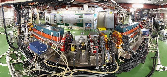
32 Most of the hardware has now been installed! Ring Area Ring Injection TL2 TL1 Delay Loop Combiner Ring CLEX TBL CALIFES Two-Beam Test Stand


33 DRIVE BEAM LINAC DELAY LOOP COMBINER RING Progress only possible through successful collaboration between 27 international institutes 10 m CLEX CLIC Experimental Area Technical programme is on track Beam to here CTF3 on schedule full beam loading bunch phase coding and Delay Loop operation First results on recombination on Combiner Ring All machine components installed (apart from TBL)

34 Matching critical issues & test facilities


35 Small emittances from Damping Rings Present CLIC DR design for 3TeV achieves goals for transverse emittances with a 20% - 30% margin (380 nm horizontal and 4.1 nm vertical) Conservative DR output emittances (2.4 μm horizontal, 10 nm vertical) for 500GeV scaled from operational or approved light source projects (NSLSII, SLS) * geometrical emittances
36 F4 X-band high-gradient and CLIC R&D for future colliders Damping Rings CLIC damping ring design Racetrack, 365 m long, E = 2.4 GeV Arcs filled with TME cells Straights filled with 2 m-long superconducting damping wigglers (2.5 T, 5 cm period) Output emittance strongly dominated by IBS Work in progress SC wiggler prototype to be built and tested at ANKA IBS theory, numerical tools Pre-damping rings optics design Radiation absorption protection, vacuum chamber design and impedance budget Design of HOM free high frequency RF cavities Collective effects evaluation (electron cloud and fast ion instability) Injection and extraction elements Diagnostics and feedback Route from 500GeV to 3TeV BINP PM wiggler BINP SC wiggler ANKA SC wiggler
37 Beam Delivery System Convergence to an optimized BDS design meet requirements on paper Recent proposal for a larger L* solution (relax final doublet alignment tolerances) The challenge remains to verify tuning in realistic simulations with dynamic effects Lots to learn from ATF2 experience ATF2 ultra-low betas proposal: demonstrate CLIC-like chromaticities


38 ATF & ATF 2
39 Beam Emittance Conservation Emittance budget: ε y 5 nm and ε x = 550 nm after damping ring Δε y 5 nm in transport to main linac Δε y 10 nm in main linac ε x = 660 nm before the beam delivery system (growth mainly in RTML) BDS budget: 20% spot size increase in the vertical plane includes design, static and dynamic effects requires 90% of the machines to perform better than the target Emittance budget is respected in simulations Tolerances are derived, iteration with experts of technical systems started Alignment & stabilization Magnets Correctors Instrumentation Feedback studies ongoing Benchmarking between codes and with beam tests
40 CLIC Technical Committee (CTC) (created in spring 2008) General objective: Towards a Project Oriented and Cost Conscious CLIC Design in preparation for the Conceptual Design Report to be edited in Specific responsibility: Set-up and keep updated an overall CLIC Work Breakdown Structure (nomenclature, components specs, documentation). Review the ensemble of technical equipments in the present CLIC design in terms of: Components specifications, technical feasibility, fabrication and industrialization, integration (machine/tunnel), machine-detector interface, installation, schedule, cost. Identify technical key issues requiring specific R&D or prototyping in view of the CDR, assess present R&D program and propose prioritized R&D. Suggest possible improvements aiming at improving the performance to cost and risk ratio. Elaborate for the CDR a baseline scenario and schedule, a CLIC baseline complex and possible options for improved performance and/or reduced cost.
41 Stabilization & Alignment Alignment LEP ground motion during 1 year 300 µm 1 mm Ground motion due to Lunar cycle (tides) Several µm 7 sec hum 100 nm, CLEX Geophones Cultural noise Accelerometers Acoustic noise becomes very important 10 nm, CLEX correction with beam-based feedbacks (limited by f REP) Slow motion f CUT 1 Hz Fast motion mechanical stability of magnets
 5 nm 1 nm Need active damping of vibrations Final Focus (4 quads, f > 5 Hz) 5 nm 0.")

42 Stabilization Vertical spot size at IP is ~ 1 nm (size of water molecule) Stability requirements for a 1% loss in luminosity Magnet Ix Iy Linac (4000 quads, f > 1 Hz) 5 nm 1 nm Need active damping of vibrations Final Focus (4 quads, f > 5 Hz) 5 nm 0.1 nm Achieved stability - CERN vibration test stand CERN vibration test stand ( ) Test made in noisy environment. Active damping reduced vibrations by a factor about 20, to rms residual amplitudes of: Vert. Horiz. 0.9 ± 0.1 nm 1.3 ± 0.2 nm with cooling water 0.4 ± 0.1 nm


43 Stabilization Extensive work done between 2001 and 2003 concerning CLIC stabilization From 2004 to 2007: Work continued only at LAPP-Annecy, France At CERN beam dynamic studies, update of stabilization requirements Collaboration between several Institutes started in 2008: LaViSta (LAPP, Universite de Savoie-SYMME ) CERN (TS, AB) JAI- Oxford University CEA-DSM-IRFU-SIS Information exchange with DESY, SLAC MONALISA IRFU/SIS

 in vac. tank DB: PETS in vac.")
44 Two-Beam module studies Module design and integration have to be studied for different configurations. Potential advantages and drawbacks are being evaluated for each configuration. Integration of the systems in terms of space reservation has been done for all the module types and detailed design started for the main systems, such vacuum, cooling, alignment, stabilisation Important aspects of cost are raised and basic parameters provided for other areas of the study. Goal: build prototype test with beam of a few modules in CTF3 from 2010 Drive beam MB: AS (quadrants) in vac. tank DB: PETS in vac. tank Quads: simplified 3D model MB: AS (disks) sealed DB: PETS with mini-tank DB Quads: updated 3D model Main beam modules (2 m long) power prod. structures PETS (drive beam) accelerating structures (main beam) Tank Version Sealed Version


45 Other technical Issues presently under investigation Civil Engineering Magnets Diagnostics Alignment & survey Vacuum Cooling & Ventilation Transport & Installation Radiation & Safety Cost & Schedule Dump 1000 kw 1000 kw Loop UTRC


46 Civil Engineering CERN sample site (in conjunction with ILC site studies) IP under CERN Prevessin site Phase 1: 0.5 TeV extension 13 km Phase 2: 3 TeV extension 48.5 km Detectors and Interaction Point CERN site Prevessin 0.5 TeV = 12.5 Km 3TeV = 47.6Km

47 Planning Based on LHC experience Consistent with 7 years construction for phase 1

48 CLIC08 Workshop All of the R&D activities I have presented (and some I didn t have the time to) were reviewed & discussed recently in the 2nd CLIC Workshop (CERN, October 2008) Participation actually larger than present CLIC/CTF3 collaboration: 215 (registered) participants from 57 Institutes of 18 countries Next CLIC Workshop tentatively scheduled for October 13-16, 2009
49 CONCLUSIONS CLIC design and R&D on all CLIC feasibility issues on schedule for completion of CDR by 2010 including: Concept of accelerator and detector Feasibility results Preliminary performance and cost R&D on complementary issues (performance and cost) to be completed and reported in a TDR with consolidated performance and cost by 2015 Consolidate/extend CTF3 in the medium term ( ) Identify, plan and execute complementary CLIC R&D in other facilities world-wide (ATF, ATF2, Cesr-TA, light sources...) Increase RF testing capabilities (New X-band sources, transform CTF3 in RF factory) Start development-industrialization of components (DBA klystrons, structures, etc...) at nominal parameters Reflection started on facility, possibly first step (re-usable) toward CLIC on 2015 time scale CLIC/CTF3 multi-lateral collaboration strong of 27 institutes from 15 countries extremely efficient and fruitful Importance of CLIC/ILC collaboration
50 A lot still to be done before the CLIC technology is mature enough to be considered for a future Linear Collider but also a lot of recent progress
51 Reserve
52 6.5 GeV,, 1.2 A TBA CALIFES type injector 0.2 GeV,, 1.2 A 0.2 GeV,, 101 A 100 m DBA 0.48 GeV,, 4.2 A DL CR1 CR2 DB Turn around 0.48 GeV,, 101 A Compression 2 x 3 x 4 all components nominal and re usable for CLIC


53 CERN DG s talk to Staff 3 October 08 N.B.: Expect additional significant contribution from outside CERN, up to the same level
54 The CLIC Technology-related key issues as pointed out by ILC-TRC 2003 R1: Feasibility Covered by CTF3 R1.1: Test of damped accelerating structure at design gradient and pulse length R1.2: Validation of drive beam generation scheme with fully loaded linac operation R1.3: Design and test of damped ON/OFF power extraction structure R2: Design finalization R2.1: Developments of structures with hard-breaking materials (W, Mo ) R2.2: Validation of stability and losses of DB decelerator; Design of machine protection system R2.3: Test of relevant linac sub-unit with beam R2.4: Validation of drive beam 40 MW, 937 MHz Multi-Beam Klystron with long RF pulse * R2.5: Effects of coherent synchrotron radiation in bunch compressors R2.6: Design of an extraction line for 3 TeV c.m. Covered by EUROTeV * Feasibility study done need development by industry. N.B.: Drive beam acc. structure parameters can be adapted to other klystron power levels
55 500 GeV comparison Table Center-of-mass energy NLC 500 GeV ILC 500 GeV CLIC 500 GeV Conservative CLIC 500 GeV Nominal Total (Peak 1%) luminosity 2.0(1.3) (1.5) (0.6) (1.4) Repetition rate (Hz) Loaded accel. gradient MV/m Main linac RF frequency GHz (SC) 12 Bunch charge Bunch separation ns Beam pulse duration (ns) Beam power/linac (MWatts) Hor./vert. norm. emitt (10-6 /10-9 ) 3.6/40 10/40 3 / / 25 Hor/Vert FF focusing (mm) 8/ /0.4 10/0.4 8/0.1 Hor./vert. IP beam size (nm) 243/3 640/ / / 2.3 Soft Hadronic event at IP Coherent pairs/crossing at IP 10? 10? BDS length (km) 3.5 (1 TeV) 2.23 (1 TeV) 1.87 Total site length (km) Wall plug to beam transfer eff. 7.1% 9.4% 7.5% Total power consumption MW
56 Cost (arbitrary scale) LC CLIC Energy (arbitrary scale)

 Full system Tested in CTF")


57 Alignment studies in CTF II Tolerance of CLIC pre-alignment: ± 10 μm transverse position over 200 m (enough to send a pilot beam, and start beam-based alignment) Full system Tested in CTF II: In a closed loop, the elements were maintained w.r.t wire within a ± 5 μm window and operated reliably in a high radiation environment WPS Wire Positioning System HLS Hydrostatic Levelling System 3 D active movers


 Red Alignment System from")
58 Active pre-alignment Some of the issues: Integration of active pre-alignment system in modules Mechanical tolerances of components on girder Tests on longer distances than CTF II Influence of gravity New methods (performance, cost) Red Alignment System from NIKHEF (RASNIK)
59 Full beam-loading acceleration in TW sections RF in No RF to load No beam High current beam short structure - low Ohmic losses most of RF power ( 95%) to the beam
60 Beam combination/separation by transverse RF deflectors P 0, ν 0 Transverse RF Deflector, ν 0 2 P 0, 2 ν 0 P 0, ν 0 Deflecting Field
61 Beam combination/separation by transverse RF deflectors P 0 / 2, ν 0 / 2 Transverse RF Deflector, ν 0 P 0, ν 0 P 0 / 2, ν 0 / 2 Deflecting Field
62 CTF3 Preliminary Phase ( ) streak camera measurement Beam structure in linac 4 pulses Beam structure after combination (factor 4) 6.6 ns 420 ns Bunch spacing 333 ps A first ring combination test was performed in 2002, at low current and short pulse, in the CERN Electron-Positron Accumulator (EPA), properly modified total length 1.3 ms - Peak Beam Current 0.3 A Bunch spacing 83 ps Pulse Length 6.6 ns Beam Peak Current 1.2 A

63 Preliminary phase results x 333 ps 83 ps Streak camera images of the beam, showing the bunch combination process t
CLIC THE COMPACT LINEAR COLLIDER
 CLIC THE COMPACT LINEAR COLLIDER Emmanuel Tsesmelis Directorate Office, CERN 9 th Corfu Summer Institute 4 September 2009 1 THE CLIC ACCELERATOR 2 Linear Collider Baseline LEP: 209 GeV next Electron-Positron
Status and Future Prospects
 Status and uture Prospects for CLIC Introduction CLIC design CLIC Test acility (CT 3) results Outlook and Conclusions Steffen öbert, LINAC 08, 29.9-3.10, 2008, Victoria, Canada Introduction CLIC = Compact
CLIC Detector studies status + plans
 CLIC Detector studies status + plans Contents: - Introduction to CLIC accelerator - 2004 CLIC Study group report: "Physics at the CLIC Multi-TeV Linear Collider - CERN participation in Linear Collider
Recent Progress at the CLIC Test Facility 3 at CERN
 Recent Progress at the CLIC Test acility 3 at CERN P. Urschütz Talk outline Introduction to the CLIC two-beam scheme The CLIC Test acility CT3 Results from CT3 Past Recent Results Outlook on future activities
Short Introduction to CLIC and CTF3, Technologies for Future Linear Colliders
 Short Introduction to CLIC and CTF3, Technologies for Future Linear Colliders Explanation of the Basic Principles and Goals Visit to the CTF3 Installation Roger Ruber Collider History p p hadron collider
THE COMPACT LINEAR COLLIDER (CLIC) STUDY
 STUDY") THE COMPACT LINEAR COLLIDER (CLIC) STUDY J.P.Delahaye for The Compact LInear Collider Study Team The CLIC study is a site independent feasibility study aiming at the development of a realistic technology
THE COMPACT LINEAR COLLIDER (CLIC) STUDY J.P.Delahaye for The Compact LInear Collider Study Team The CLIC study is a site independent feasibility study aiming at the development of a realistic technology
Status of linear collider designs:
 Status of linear collider designs: Main linacs Design overview, principal open issues G. Dugan March 11, 2002 Linear colliders: main linacs The main linac is the heart of the linear collider TESLA, NLC/JLC,
e + e - Linear Collider
 e + e - Linear Collider Disclaimer This talk was lifted from an earlier version of a lecture by N.Walker Eckhard Elsen DESY DESY Summer Student Lecture 3 rd August 2006 1 Disclaimer II Talk is largely
THE ACTIVE PREALIGNMENT OF THE CLIC COMPONENTS H. MAINAUD DURAND, T. TOUZE CERN
 THE ACTIVE PREALIGNMENT OF THE CLIC COMPONENTS H. MAINAUD DURAND, T. TOUZE CERN Overview Introduction : the CLIC study The alignment of CLIC Steps of alignment The active prealignment The situation of
THE CLIC PROJECT - STATUS AND PROSPECTS
 THE CLIC PROJECT - STATUS AND PROSPECTS E. Adli, University of Oslo, Norway On behalf of the CLIC/CTF3 collaboration Abstract Following the feasibility demonstration of the novel CLIC technology and the
Current and Future Developments in Accelerator Facilities. Jordan Nash, Imperial College London
 Current and Future Developments in Accelerator Facilities Jordan Nash, Imperial College London Livingston chart (circa 1985) Nearly six decades of continued growth in the energy reach of accelerators Driven
High-gradient X-band RF technology for CLIC and beyond
 High-gradient X-band RF technology for CLIC and beyond Philip Burrows 1 Oxford University Oxford, UK E-mail: Philip.Burrows@physics.ox.ac.uk Walter Wuensch CERN Geneva, Switzerland E-mail: Walter.Wuensch@cern.ch
WG2 on ERL light sources CHESS & LEPP
 Charge: WG2 on ERL light sources Address and try to answer a list of critical questions for ERL light sources. Session leaders can approach each question by means of (a) (Very) short presentations (b)
Report from the Luminosity Working Group of the International Linear Collider Technical Review Committee (ILC-TRC) Chairman: Greg Loew
 Chairman: Greg Loew") Report from the Luminosity Working Group of the International Linear Collider Technical Review Committee (ILC-TRC) Chairman: Greg Loew The ILC-TRC was originally constituted in 1994 and produced a report
Report from the Luminosity Working Group of the International Linear Collider Technical Review Committee (ILC-TRC) Chairman: Greg Loew The ILC-TRC was originally constituted in 1994 and produced a report
The TESLA Dogbone Damping Ring
 The TESLA Dogbone Damping Ring Winfried Decking for the TESLA Collaboration April 6 th 2004 Outline The Dogbone Issues: Kicker Design Dynamic Aperture Emittance Dilution due to Stray-Fields Collective
Towards a CLIC detector, opportunities for R&D. Lucie Linssen CERN
 Towards a CLIC detector, opportunities for R&D Lucie Linssen CERN 1 Outline: Outline and useful links Short introduction to the CLIC accelerator CLIC physics CLIC detector issues
CLIC Project Status. Roger Ruber. Uppsala University. On behalf of the CLIC Collaborations. Thanks to all colleagues for materials
 CLIC Project Status Roger Ruber Uppsala University On behalf of the CLIC Collaborations Thanks to all colleagues for materials IAS 2018 Program on High Energy Physics Hong Kong, 23 January 2018 CLIC Collaborations
COMBINER RING LATTICE
 CTFF3 TECHNICAL NOTE INFN - LNF, Accelerator Division Frascati, April 4, 21 Note: CTFF3-2 COMBINER RING LATTICE C. Biscari 1. Introduction The 3 rd CLIC test facility, CTF3, is foreseen to check the feasibility
CLIC 3TeV. Per linac: Module: Accelerating structures: PETS: MB quadrupoles: 1996 DB quadrupoles: 20920
 C L I C Outline Short overview of the CLIC project Timelines CLIC feasibility demonstration Stabilization of Main Beam Quadrupoles Experimental verification of Quadrupole stability Outlook for JLAB collaboration
CLIC Status. Philip Burrows. John Adams Institute Oxford University
 CLIC Status Philip Burrows John Adams Institute Oxford University 1 CLIC Collaboration 29 Countries over 70 Institutes Accelerator collaboration Detector collaboration Accelerator + Detector collaboration
A 6 GeV Compact X-ray FEL (CXFEL) Driven by an X-Band Linac
 Driven by an X-Band Linac") A 6 GeV Compact X-ray FEL (CXFEL) Driven by an X-Band Linac Zhirong Huang, Faya Wang, Karl Bane and Chris Adolphsen SLAC Compact X-Ray (1.5 Å) FEL Parameter symbol LCLS CXFEL unit Bunch Charge Q 250 250
A 6 GeV Compact X-ray FEL (CXFEL) Driven by an X-Band Linac Zhirong Huang, Faya Wang, Karl Bane and Chris Adolphsen SLAC Compact X-Ray (1.5 Å) FEL Parameter symbol LCLS CXFEL unit Bunch Charge Q 250 250
Towards a Multi TeV Linear Collider; Drive Beam Generation with CTF3
 Towards a Multi TeV Linear Collider; rive Beam Generation with CT3 H.H. Braun / CERN, on behalf of the CT3 collaboration Introduction CLIC & CT3 CT3 status and achievements CT3 outlook CLIC aim: develop
CERN EUROPEAN ORGANIZATION FOR NUCLEAR RESEARCH ADVANCES IN HIGH-GRADIENT ACCELERATING STRUCTURES AND IN THE UNDERSTANDING GRADIENT LIMITS
 CERN EUROPEAN ORGANIZATION FOR NUCLEAR RESEARCH CLIC Note 1111 ADVANCES IN HIGH-GRADIENT ACCELERATING STRUCTURES AND IN THE UNDERSTANDING GRADIENT LIMITS Walter Wuensch CERN, Geneva, Switzerland Abstract
Critical R&D Issues for ILC Damping Rings and New Test Facilities
 Critical R&D Issues for ILC Damping Rings and New Test Facilities Andy Wolski Cockcroft Institute/University of Liverpool PAC 2007, Albuquerque, New Mexico. 1 ILC Key Parameters Given the main linac parameters:
On the future plan of KEK for ILC(International Linear Collider) Junji Urakawa(KEK) Contents
 Junji Urakawa(KEK) Contents") On the future plan of KEK for ILC(International Linear Collider) Junji Urakawa(KEK) 2004.10.24 Contents 0. Outline until now. Review of SC-LC(TESLA) and R&D items. R&D Items at ATF. R&D plans for Superconducting
On the future plan of KEK for ILC(International Linear Collider) Junji Urakawa(KEK) 2004.10.24 Contents 0. Outline until now. Review of SC-LC(TESLA) and R&D items. R&D Items at ATF. R&D plans for Superconducting
Thanks to all Contributors
 Thanks to all Contributors High Gradient versus High Field Dr. José Miguel Jiménez CERN Technology Department Head CERN-Spain Liaison Officer 2 Main topics A worldwide success? Full exploitation of the
Status of Accelerator R&D at ILC
 Status of Accelerator R&D at ILC 2013 년 8 월 12 일 경북대김은산 1 The Beginning an idea A Possible Apparatus for Electron-Clashing Experiments (*). M. Tigner Laboratory of Nuclear Studies. Cornell University -
PARTICLE BEAMS, TOOLS FOR MODERN SCIENCE AND MEDICINE Hans-H. Braun, CERN
 5 th Particle Physics Workshop National Centre for Physics Quaid-i-Azam University Campus, Islamabad PARTICLE BEAMS, TOOLS OR MOERN SCIENCE AN MEICINE Hans-H. Braun, CERN 3 rd Lecture Introduction to Linear
LHC Luminosity and Energy Upgrade
 LHC Luminosity and Energy Upgrade Walter Scandale CERN Accelerator Technology department EPAC 06 27 June 2006 We acknowledge the support of the European Community-Research Infrastructure Activity under
Microwave-Based High-Gradient Structures and Linacs
 Microwave-Based High-Gradient Structures and Linacs Sami Tantawi SLAC 7/10/2009 1 Acknowledgment The work being presented is due to the efforts of V. Dolgashev, L. Laurent, F. Wang, J. Wang, C. Adolphsen,
CLIC polarized e+ source based on laser Compton scattering
 CLIC polarized e+ source based on laser Compton scattering Frank Zimmermann CLIC Meeting, 16. December 2005 Thanks to Eugene Bulyak, Masao Kuriki, Klaus Moenig, Tsunehiko Omori, Junji Urakawa, Alessandro
Possible improvement of the CLIC accelerating structure. From CLIC_G to CLIC_K.
 Possible improvement of the CLIC accelerating structure. From CLIC_G to CLIC_K. 2.07.2009 Alexej Grudiev CERN Outline Current CLIC accelerating structure: CLIC_G Compact coupler design with damping Comparison
ILC Beam Dynamics Studies Using PLACET
 ILC Beam Dynamics Studies Using PLACET Andrea Latina (CERN) July 11, 2007 John Adams Institute for Accelerator Science - Oxford (UK) Introduction Simulations Results Conclusions and Outlook PLACET Physical
III. CesrTA Configuration and Optics for Ultra-Low Emittance David Rice Cornell Laboratory for Accelerator-Based Sciences and Education
 III. CesrTA Configuration and Optics for Ultra-Low Emittance David Rice Cornell Laboratory for Accelerator-Based Sciences and Education Introduction Outline CESR Overview CESR Layout Injector Wigglers
ELIC Design. Center for Advanced Studies of Accelerators. Jefferson Lab. Second Electron-Ion Collider Workshop Jefferson Lab March 15-17, 2004
 ELIC Design Ya. Derbenev, K. Beard, S. Chattopadhyay, J. Delayen, J. Grames, A. Hutton, G. Krafft, R. Li, L. Merminga, M. Poelker, E. Pozdeyev, B. Yunn, Y. Zhang Center for Advanced Studies of Accelerators
OVERVIEW OF THE LHEC DESIGN STUDY AT CERN
 OVERVIEW OF THE LHEC DESIGN STUDY AT CERN 1 CERN CH-1211 Geneve 23, Switzerland E-mail: Oliver.bruning@cern.ch Abstract The Large Hadron electron Collider (LHeC) offers the unique possibility of exploring
ELIC: A High Luminosity And Efficient Spin Manipulation Electron-Light Ion Collider Based At CEBAF
 ELIC: A High Luminosity And Efficient Spin Manipulation Electron-Light Ion Collider Based At CEBAF Lia Merminga and Yaroslav Derbenev Center for Advanced Studies of Accelerators, Jefferson Laboratory,
Proposal for a US strategy towards physics & detectors at future lepton colliders
 Proposal for a US strategy towards physics & detectors at future lepton colliders Argonne National Laboratory Brookhaven National Laboratory Fermi National Accelerator Laboratory Lawrence Berkeley National
FACET-II Design Update
 FACET-II Design Update October 17-19, 2016, SLAC National Accelerator Laboratory Glen White FACET-II CD-2/3A Director s Review, August 9, 2016 Planning for FACET-II as a Community Resource FACET-II Photo
LC Commissioning, Operations and Availability
 International Technology Recommendation Panel X-Band Linear Collider Path to the Future LC Commissioning, Operations and Availability Tom Himel Stanford Linear Accelerator Center April 26-27, 2004 Integrating
Super-c-tau factory in Novosibirsk (WP7)
") Super-c-tau factory in Novosibirsk (WP7) E. Levichev Budker Institute of Nuclear Physics Novosibirsk, RUSSIA CREMLIN kick-off meeting, 6-7 October 2015 NRC Kurchatov Institute Budker Institute Founded
Super-c-tau factory in Novosibirsk (WP7) E. Levichev Budker Institute of Nuclear Physics Novosibirsk, RUSSIA CREMLIN kick-off meeting, 6-7 October 2015 NRC Kurchatov Institute Budker Institute Founded
Lattice Design and Performance for PEP-X Light Source
 Lattice Design and Performance for PEP-X Light Source Yuri Nosochkov SLAC National Accelerator Laboratory With contributions by M-H. Wang, Y. Cai, X. Huang, K. Bane 48th ICFA Advanced Beam Dynamics Workshop
1.1 Report on the First ILC Workshop, KEK (Japan) November 04
 November 04") 5 1.1 Report on the First ILC Workshop, KEK (Japan) November 04 1.1.1 Introduction Susanna Guiducci mail to: Susanna.Guiducci@lnf.infn.it LNF-INFN, Frascati, Italy The First International Linear Collider
5 1.1 Report on the First ILC Workshop, KEK (Japan) November 04 1.1.1 Introduction Susanna Guiducci mail to: Susanna.Guiducci@lnf.infn.it LNF-INFN, Frascati, Italy The First International Linear Collider
The International Linear Collider. Barry Barish Caltech 2006 SLUO Annual Meeting 11-Sept-06
 The International Linear Collider Barry Barish Caltech 2006 SLUO Annual Meeting 11-Sept-06 Why e + e - Collisions? elementary particles well-defined energy, angular momentum uses full COM energy produces
CARE-ELAN Final Report
 CARE-ELAN Final Report ELAN in Summary: Country Number of institutes Finland 1 3 France 8 70 Germany 12 130 Italy 5 45 Netherlands 2 7 Poland 3 20 Portugal 1 3 Spain 3 9 Sweden 1 2 Switzerland 2 3 United
Plans for CESR (or Life Without CLEO)
") CESR-c Plans for CESR (or Life Without CLEO) Mark A. Palmer David L. Rubin Second ILC Accelerator Workshop August 18, 2005 2 Outline CESR-c/CLEO-c Schedule Preliminary Concept Possibilities for CESR as
CESR-c Plans for CESR (or Life Without CLEO) Mark A. Palmer David L. Rubin Second ILC Accelerator Workshop August 18, 2005 2 Outline CESR-c/CLEO-c Schedule Preliminary Concept Possibilities for CESR as
CLIC ACCELERATING STRUCTURE DEVELOPMENT
 CLIC ACCELERATING STRUCTURE DEVELOPMENT W. Wuensch, CERN, Geneva, Switzerland. Abstract One of the most important objectives of the CLIC (Compact Linear Collider) study is to demonstrate the design accelerating
Proton-driven plasma wakefield acceleration
 Proton-driven plasma wakefield acceleration Matthew Wing (UCL) Motivation : particle physics; large accelerators General concept : proton-driven plasma wakefield acceleration Towards a first test experiment
Challenges of the Beam Delivery System for the future Linear Colliders
 Challenges of the Beam Delivery System for the future s Eduardo Marin eduardo.marin.lacoma@cern.ch Dual year Russia-Spain: Particle Physics, Nuclear Physics and Astroparticle Physics Barcelona, SPAIN 10
Transverse dynamics Selected topics. Erik Adli, University of Oslo, August 2016, v2.21
 Transverse dynamics Selected topics Erik Adli, University of Oslo, August 2016, Erik.Adli@fys.uio.no, v2.21 Dispersion So far, we have studied particles with reference momentum p = p 0. A dipole field
High average current photo injector (PHIN) for the CLIC Test Facility at CERN
 for the CLIC Test Facility at CERN") High average current photo injector (PHIN) for the CLIC Test Facility at CERN CLIC and CTF3 motivation Photo injectors, PHIN Emittance measurements Long pulse operation, time resolved measurements Cathode
High average current photo injector (PHIN) for the CLIC Test Facility at CERN CLIC and CTF3 motivation Photo injectors, PHIN Emittance measurements Long pulse operation, time resolved measurements Cathode
The CLIC active prealignment studies H. MAINAUD DURAND, T. TOUZE CERN
 The CLIC active prealignment studies H. MAINAUD DURAND, T. TOUZE CERN Overview The alignment of CLIC Steps of alignment The active prealignment The situation of the studies on the active prealignment Studies
NLC Luminosity and Accelerator Physics
 Stanford Linear Accelerator Center X-Band Linear Collider Path to the Future NLC Luminosity and Accelerator Physics International Technology Recommendation Panel April 26-27, 2004 Outline Talk will focus
LAYOUT AND SIMULATIONS OF THE FONT SYSTEM AT ATF2
 LAYOUT AND SIMULATIONS OF THE FONT SYSTEM AT ATF J. Resta-López, P. N. Burrows, JAI, Oxford University, UK August 1, Abstract We describe the adaptation of a Feedback On Nano-second Timescales (FONT) system
CesrTA Status Report Mark Palmer for the CesrTA Collaboration March 4, 2009 ESR
 CesrTA Status Report Mark Palmer for the CesrTA Collaboration March 4, 2009 ESR Outline Recent Updates January run/february Down Overview Optics & LET xbsm Electron Cloud Studies Tune Data-Simulation Comparisons
Beam Dynamics study in Linear Colliders. IJAZ AHMED National Centre for Physics, Islamabad
 Beam Dynamics study in Linear Colliders IJAZ AHMED National Centre for Physics Islamabad Ijaz Ahmed National Centre for Physics Islamabad 29-31 December 2009 Outlines Introduction of CLIC Introduction
CERN & the High Energy Frontier
 CERN & the High Energy Frontier Emmanuel Tsesmelis CERN Directorate Office Corfu Summer Institute 13th Hellenic School & Workshop on Elementary Particle Physics & Gravity Corfu, Greece 1 September 2013
International Linear Collider ILC Overview
 International Linear Collider ILC Overview Lyn EVANS, Shinichiro MICHIZONO and Akira YAMAMOTO The International Linear Collider (ILC) is proposed as an energy frontier electron-positron colliding accelerator,
SPPC Study and R&D Planning. Jingyu Tang for the SPPC study group IAS Program for High Energy Physics January 18-21, 2016, HKUST
 SPPC Study and R&D Planning Jingyu Tang for the SPPC study group IAS Program for High Energy Physics January 18-21, 2016, HKUST Main topics Pre-conceptual design study Studies on key technical issues R&D
ILC concepts / schematic
 INFN School on Electron Accelerators 12-14 September 2007, INFN Sezione di Pisa Lecture 1a ILC concepts / schematic Carlo Pagani University of Milano INFN Milano-LASA & GDE The Standard Model Fundamental
Accelerator R&D Opportunities: Sources and Linac. Developing expertise. D. Rubin, Cornell University
 Accelerator R&D Opportunities: Sources and Linac D. Rubin, Cornell University Electron and positron sources Requirements Status of R&D Linac Modeling of beam dynamics Development of diagnostic and tuning
6 Bunch Compressor and Transfer to Main Linac
 II-159 6 Bunch Compressor and Transfer to Main Linac 6.1 Introduction The equilibrium bunch length in the damping ring (DR) is 6 mm, too long by an order of magnitude for optimum collider performance (σ
SPPS: The SLAC Linac Bunch Compressor and Its Relevance to LCLS
 LCLS Technical Advisory Committee December 10-11, 2001. SPPS: The SLAC Linac Bunch Compressor and Its Relevance to LCLS Patrick Krejcik LCLS Technical Advisory Committee Report 1: July 14-15, 1999 The
The Turkish Accelerator Center (TAC) Project. Bora Ketenoğlu. Department of Engineering Physics Ankara University / TURKEY
 Project. Bora Ketenoğlu. Department of Engineering Physics Ankara University / TURKEY") The Turkish Accelerator Center (TAC) Project Bora Ketenoğlu Department of Engineering Physics Ankara University / TURKEY Contents The emblem & homepage Why do we want to build an accelerator complex? Where
The Turkish Accelerator Center (TAC) Project Bora Ketenoğlu Department of Engineering Physics Ankara University / TURKEY Contents The emblem & homepage Why do we want to build an accelerator complex? Where
Beam-beam Effects in Linear Colliders
 Beam-beam Effects in Linear Colliders Daniel Schulte D. Schulte Beam-beam effects in Linear Colliders 1 Generic Linear Collider Single pass poses luminosity challenge Low emittances are produced in the
LHC Upgrade Plan and Ideas - scenarios & constraints from the machine side
 LHC Upgrade Plan and Ideas - scenarios & constraints from the machine side Frank Zimmermann LHCb Upgrade Workshop Edinburgh, 11 January 2007 Frank Zimmermann, LHCb Upgrade Workshop time scale of LHC upgrade
CERN EUROPEAN ORGANIZATION FOR NUCLEAR RESEARCH THE CLIC POSITRON CAPTURE AND ACCELERATION IN THE INJECTOR LINAC
 CERN EUROPEAN ORGANIZATION FOR NUCLEAR RESEARCH CLIC Note - 819 THE CLIC POSITRON CAPTURE AND ACCELERATION IN THE INJECTOR LINAC A. Vivoli 1, I. Chaikovska 2, R. Chehab 3, O. Dadoun 2, P. Lepercq 2, F.
AWAKE: The Proton Driven Plasma Wakefield Acceleration Experiment at CERN. Alexey Petrenko on behalf of the AWAKE Collaboration
 AWAKE: The Proton Driven Plasma Wakefield Acceleration Experiment at CERN Alexey Petrenko on behalf of the AWAKE Collaboration Outline Motivation AWAKE at CERN AWAKE Experimental Layout: 1 st Phase AWAKE
ERL FACILITY AT CERN FOR APPLICATIONS
 ERL FACILITY AT CERN FOR APPLICATIONS Erk Jensen (CERN) Big thanks to contributors: A. Bogacz (JLAB), O. Brüning, R. Calaga, V. Chetvertkova, E. Cormier (CELIA), R. Jones, M. Klein, A. Valloni, D. Pellegrini,
THE ILC BEAM DELIVERY SYSTEM DESIGN AND R&D PROGRAMME
 THE ILC BEAM DELIVERY SYSTEM DESIGN AND R&D PROGRAMME T. Tauchi, KEK, 1-1 Oho, Tsukuba, Ibaraki, 306-0801, Japan Abstract The International Linear Collider (ILC) beam delivery system (BDS) has been designed
Tools of Particle Physics I Accelerators
 Tools of Particle Physics I Accelerators W.S. Graves July, 2011 MIT W.S. Graves July, 2011 1.Introduction to Accelerator Physics 2.Three Big Machines Large Hadron Collider (LHC) International Linear Collider
BEAM TESTS OF THE LHC TRANSVERSE FEEDBACK SYSTEM
 JINR BEAM TESTS OF THE LHC TRANSVERSE FEEDBACK SYSTEM W.Höfle, G.Kotzian, E.Montesinos, M.Schokker, D.Valuch (CERN) V.M. Zhabitsky (JINR) XXII Russian Particle Accelerator Conference 27.9-1.1. 21, Protvino
SLS at the Paul Scherrer Institute (PSI), Villigen, Switzerland
, Villigen, Switzerland") SLS at the Paul Scherrer Institute (PSI), Villigen, Switzerland Michael Böge 1 SLS Team at PSI Michael Böge 2 Layout of the SLS Linac, Transferlines Booster Storage Ring (SR) Beamlines and Insertion Devices
SLS at the Paul Scherrer Institute (PSI), Villigen, Switzerland Michael Böge 1 SLS Team at PSI Michael Böge 2 Layout of the SLS Linac, Transferlines Booster Storage Ring (SR) Beamlines and Insertion Devices
Optics considerations for
 Optics considerations for ERL x-ray x sources Georg H. Hoffstaetter* Physics Department Cornell University Ithaca / NY Georg.Hoffstaetter@cornell.edu 1. Overview of Parameters 2. Critical Topics 3. Phase
LHC operation in 2015 and prospects for the future
 LHC operation in 2015 and prospects for the future Moriond Workshop La Thuile March 2016 Jörg Wenninger CERN Beams Department Operation group / LHC For the LHC commissioning and operation teams 1 Moriond
X-band Experience at FEL
 X-band Experience at FERMI@Elettra FEL Gerardo D Auria Elettra - Sincrotrone Trieste GdA_TIARA Workshop, Ångström Laboratory, June 17-19, 2013 1 Outline The FERMI@Elettra FEL project Machine layout and
BEPC AND THE FUTURE PROGRAM AT IHEP
 BEPC AND THE FUTURE PROGRAM AT IHEP Z.T. Zhao, S.H.Wang of BEPC Group IHEP, Chinese Academy of Sciences, P.O.Box 918, Beijing 100039, P.R.China Abstract Beijing Electron and Positron Collider (BEPC), a
First propositions of a lattice for the future upgrade of SOLEIL. A. Nadji On behalf of the Accelerators and Engineering Division
 First propositions of a lattice for the future upgrade of SOLEIL A. Nadji On behalf of the Accelerators and Engineering Division 1 SOLEIL : A 3 rd generation synchrotron light source 29 beamlines operational
Advanced Design of the FAIR Storage Ring Complex
 Advanced Design of the FAIR Storage Ring Complex M. Steck for the FAIR Technical Division and the Accelerator Division of GSI The FAIR Accelerator Facility SIS300 existing GSI proton linac SIS18 UNILAC
Introduction. Thermoionic gun vs RF photo gun Magnetic compression vs Velocity bunching. Probe beam design options
 Introduction Following the 19/05/04 meeting at CERN about the "CTF3 accelerated programme", a possible french contribution has been envisaged to the 200 MeV Probe Beam Linac Two machine options were suggested,
International Scientific Spring 2010, March 1-6, 1. R. Garoby. slhc
 International Scientific Spring 2010, March 1-6, 1 2010 R. Garoby slhc 1. Plans for future LHC injectors 2. Implementation stages 3. Final words R.G. 2 3/10/2009 R.G. 3 3 3/10/2009 Motivation 1. Reliability
Physics 736. Experimental Methods in Nuclear-, Particle-, and Astrophysics. - Accelerator Techniques: Introduction and History -
 Physics 736 Experimental Methods in Nuclear-, Particle-, and Astrophysics - Accelerator Techniques: Introduction and History - Karsten Heeger heeger@wisc.edu Homework #8 Karsten Heeger, Univ. of Wisconsin
ThomX Machine Advisory Committee. (LAL Orsay, March ) Ring Beam Dynamics
 Ring Beam Dynamics") ThomX Machine Advisory Committee (LAL Orsay, March 20-21 2017) Ring Beam Dynamics A. Loulergue, M. Biagini, C. Bruni, I. Chaikovska I. Debrot, N. Delerue, A. Gamelin, H. Guler, J. Zang Programme Investissements
ThomX Machine Advisory Committee (LAL Orsay, March 20-21 2017) Ring Beam Dynamics A. Loulergue, M. Biagini, C. Bruni, I. Chaikovska I. Debrot, N. Delerue, A. Gamelin, H. Guler, J. Zang Programme Investissements
The 2015 erhic Ring-Ring Design. Christoph Montag Collider-Accelerator Department Brookhaven National Laboratory
 The 2015 erhic Ring-Ring Design Christoph Montag Collider-Accelerator Department Brookhaven National Laboratory The Relativistic Heavy Ion Collider RHIC Two superconducting storage rings 3833.845 m circumference
Wakefield Suppression for CLIC A Manifold Damped and Detuned Structure
 Wakefield Suppression for CLIC A Manifold Damped and Detuned Structure Roger M. Jones Cockcroft Institute and The University of Manchester 1 Wake 2. Function FP420 RF Suppression Staff for CLIC -Staff
M. Biagini, LAL & INFN French-Ukrainian Workshop on the instrumentation developments for high energy physics LAL, November
 M. Biagini, LAL & INFN French-Ukrainian Workshop on the instrumentation developments for high energy physics LAL, November 6-8 2017 Why a new t/charm-factory? Physics at rather low energy is still interesting
Jan. 5, 2006 Development of a Helical Undulator for ILC Positron Source
 Jan. 5, 2006 Development of a Helical Undulator for ILC Positron Source Abstract. The long-term goal of this research is the development of a polarized positron source able to satisfy the demands of the
Numerical study of FII in the ILC Damping Ring
 Numerical study of FII in the ILC Damping Ring L. Wang, Y. Cai and T. Raubenheimer SLAC LCDR07 - Damping Rings R&D Meeting March 5-7, 2007 INFN-LNF, Frascati Outline Introduction Simulation Wake of ion
Accelerator Physics. Accelerator Development
 Accelerator Physics The Taiwan Light Source (TLS) is the first large accelerator project in Taiwan. The goal was to build a high performance accelerator which provides a powerful and versatile light source
Simulation of Laser-wires at CLIC using BDSIM
 Simulation of Laser-wires at CLIC using BDSIM Grahame A. Blair, Royal Holloway Univ of London, UK. Abstract A laserwire system within the CLIC beam delivery system is simulated using Geant4. The issues
The FAIR Accelerator Facility
 The FAIR Accelerator Facility SIS300 existing GSI proton linac SIS18 UNILAC SIS100 HESR pbar target SuperFRS goals: higher intensity (low charge states) higher energy (high charge states) production of
Linear Collider Collaboration Tech Notes
 LCC 0035 07/01/00 Linear Collider Collaboration Tech Notes More Options for the NLC Bunch Compressors January 7, 2000 Paul Emma Stanford Linear Accelerator Center Stanford, CA Abstract: The present bunch
Steering Simulation Studies
 Steering Simulation Studies Machine Advisory Committee Meeting 24 June 23 The Situation in November 2 Capability to realistically simulate both commissioning and operation of any proposed LC is critical
Diagnostics Needs for Energy Recovery Linacs
 Diagnostics Needs for Energy Recovery Linacs Georg H. Hoffstaetter Cornell Laboratory for Accelerator-based Sciences and Education & Physics Department Cornell University, Ithaca New York 14853-2501 gh77@cornell.edu
4GLS Status. Susan L Smith ASTeC Daresbury Laboratory
 4GLS Status Susan L Smith ASTeC Daresbury Laboratory Contents ERLP Introduction Status (Kit on site ) Plan 4GLS (Conceptual Design) Concept Beam transport Injectors SC RF FELs Combining Sources May 2006
Two Beamline Ground Motion Simulation for NLC
 Two Beamline Ground Motion Simulation for NLC LCD group meeting May 28, 2002 Andrei Seryi for the NLC Accelerator Physics Group 1 of 25 Goal: Create a tool which will allow simulation of realistic behavior
Superconducting RF Accelerators: Why all the interest?
 Superconducting RF Accelerators: Why all the interest? William A. Barletta Director, United States Particle Accelerator School Dept. of Physics, MIT The HEP prespective ILC PROJECT X Why do we need RF
Studies of Higgs hadronic decay channels at CLIC. IMPRS Young Scientist Workshop at Ringberg Castle 18 th July 2014 Marco Szalay
 Studies of Higgs hadronic decay channels at CLIC IMPRS Young Scientist Workshop at Ringberg Castle 8 th July 24 Outline Physics at e + e - colliders CLIC - collider and detectors BDT intermezzo Higgs branching
LHC Status and CERN s future plans. Lyn Evans
 LHC Status and CERN s future plans Lyn Evans Machine layout L. Evans EDMS document no. 859415 2 Cryodipole overview 1250 1000 Equivalent dipoles 750 500 250 0 01-Jan-01 01-Jan-02 01-Jan-03 01-Jan-04 01-Jan-05
FACET-II Design, Parameters and Capabilities
 FACET-II Design, Parameters and Capabilities 217 FACET-II Science Workshop, October 17-2, 217 Glen White Overview Machine design overview Electron systems Injector, Linac & Bunch compressors, Sector 2