Diagnostics Needs for Energy Recovery Linacs
|
|
|
- Rosemary Park
- 6 years ago
- Views:
Transcription


1 Diagnostics Needs for Energy Recovery Linacs Georg H. Hoffstaetter Cornell Laboratory for Accelerator-based Sciences and Education & Physics Department Cornell University, Ithaca New York Plans for x-ray ERLs x-ray ERL challenges x-ray ERL diagnostics needs Ongoing R&D High current FEL-ERL challenges High current ERL-FEL diagnostics needs
2 x-ray ERL upgrade to CESR Cornell Electron Storage Ring Tunnel Key: 1) injector, 2) north linac, 3)turn-around arc, 4) south linac, 5) south x-ray beamlines, 6) CESR turn-around, 7) north x-ray beamlines, 8) 1st beam dump, 9) 2nd beam dump and 10)distributed cryoplant. Tunnel cross-section of 12 ID shown on lower right. Georg H. Hoffstaetter Scientific Assessment of FEL Technology Panel of the National Academy of Sciences 04 / 05 / 2008
3 5GeV ERL Upgrade for CESR Cornell ERL
4 5GeV ERL Upgrade ERLs for CESR Cornell / KEK / JAEA ERLs KEK 5GeV-ERL JAEA Naka (East) JAEA Naka (West) 240m 6GeV-ERL 650m
5 5GeV ERL Upgrade for ERLs CESR Cornell / KEK / JAEA / APS ERLs KEK 5GeV-ERL JAEA Naka (East) APS 7GeV ERL JAEA Naka (West) 240m 6GeV-ERL 650m
6 How large is the advantage of ERLs?
7 The injector: goals for the ERL Energy recovered modes One pass Modes: (A) Flux (B) Coherence (C) Short-Pulse (D) Short & High charge Units Energy GeV Current ma Bunch charge pc Repetition rate MHz Norm. emittance mm mrad Geom. emittance pm Rms bunch length tbd by CSR 100 fs Relative energy spread Beam power MW Beam loss < 1 < 1 < 1 <1 micro A
8 (1) Challenges for x-ray ERLs Production of low emittances Space charge compensation in the injector Diagnostics needs Phase space measurement for injector setup Laser diagnostics for bunch position and bunch timing feedback Laser diagnostics for transverse and longitudinal profile


9 Multivariable optimization to worlds highest electron brightness Some initial, promising results Space charge emittance growth above 1µm ε = 0.1µm CSR emittance growth above 1µm This work has continued steadily, currently being optimized for a detailed injector design to: 15MeV injection energy, 3ps bunch length, 0.3µm emittances for 77pC. ε = 0.1µm lead to further study, and experimental tests

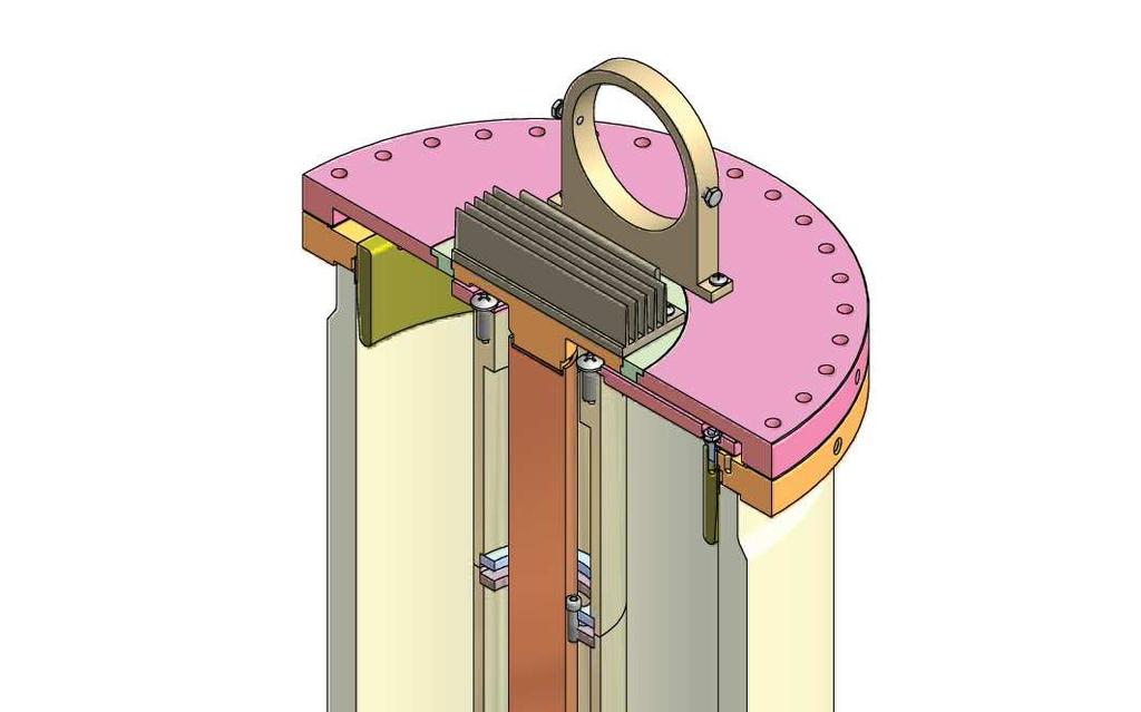
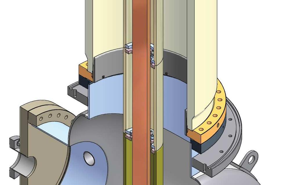
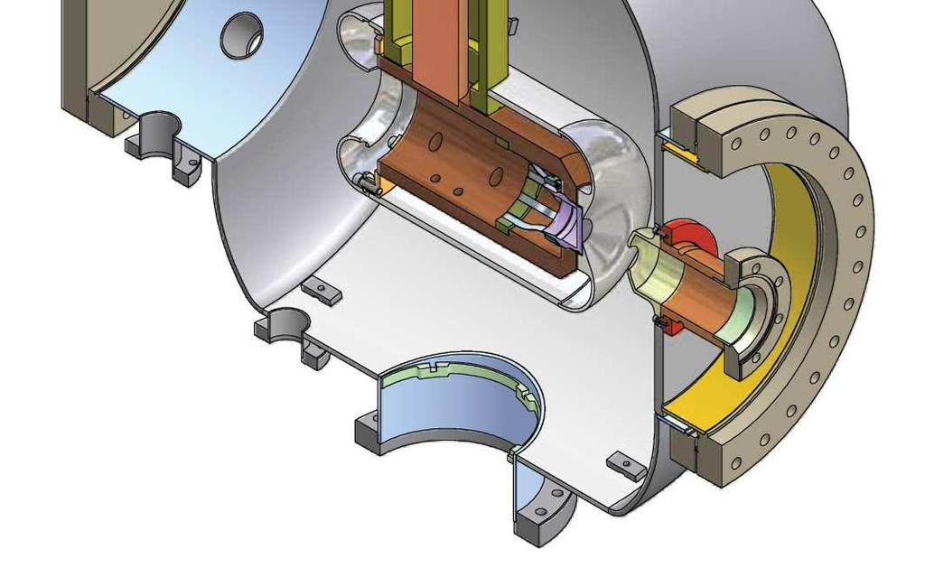
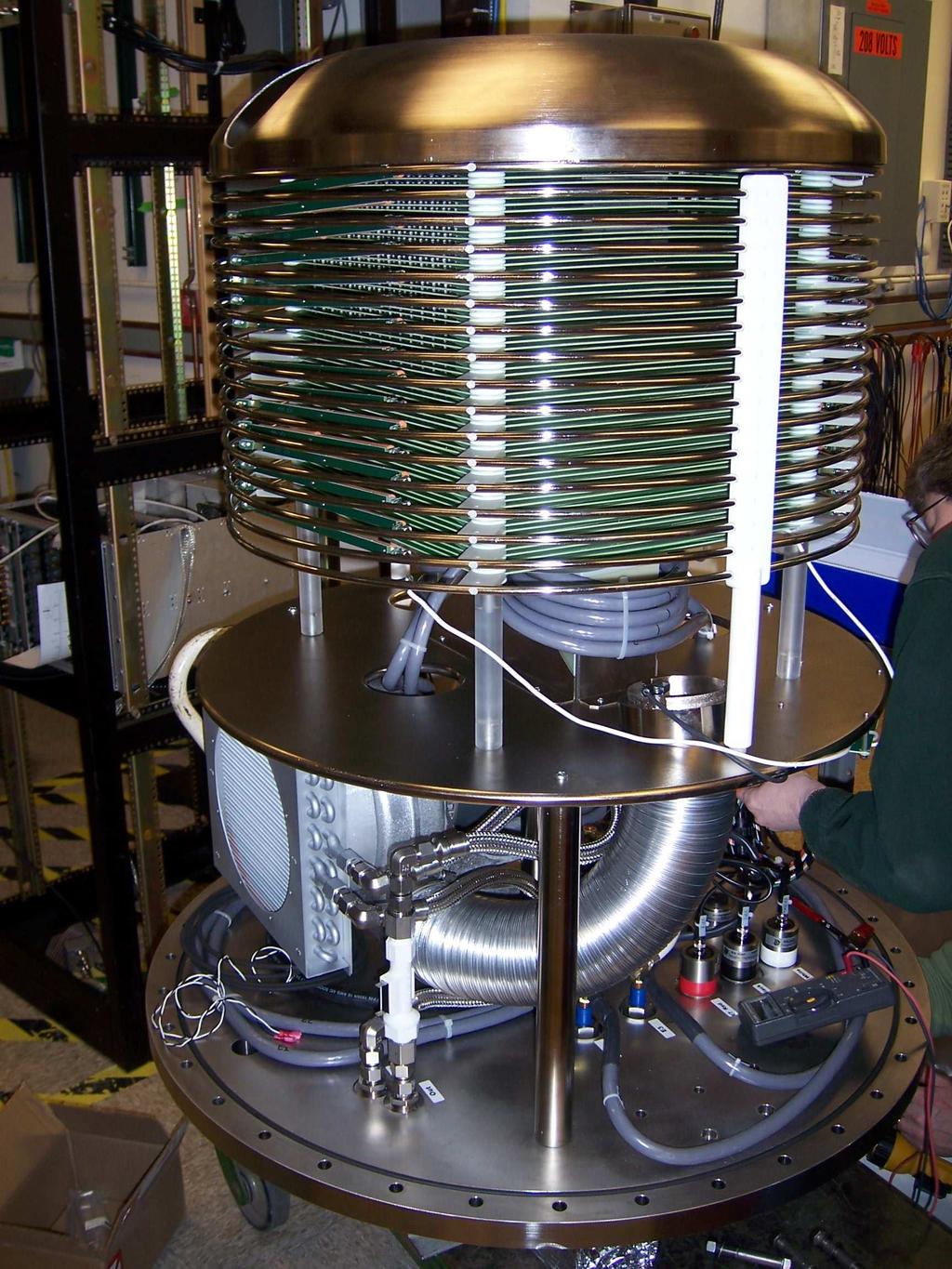
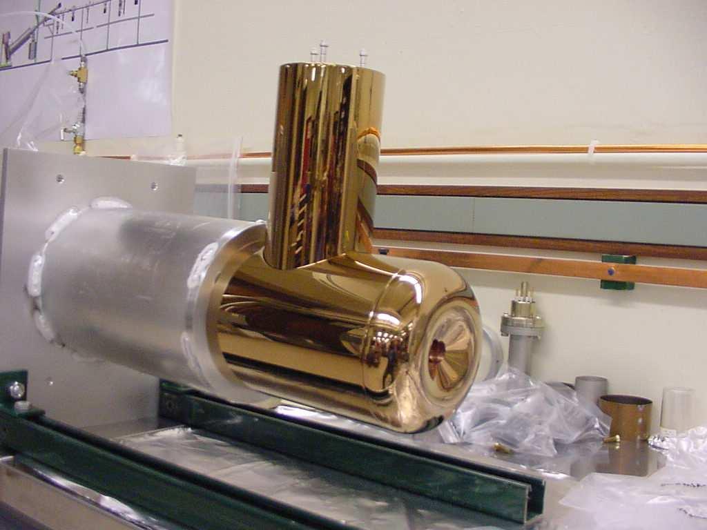
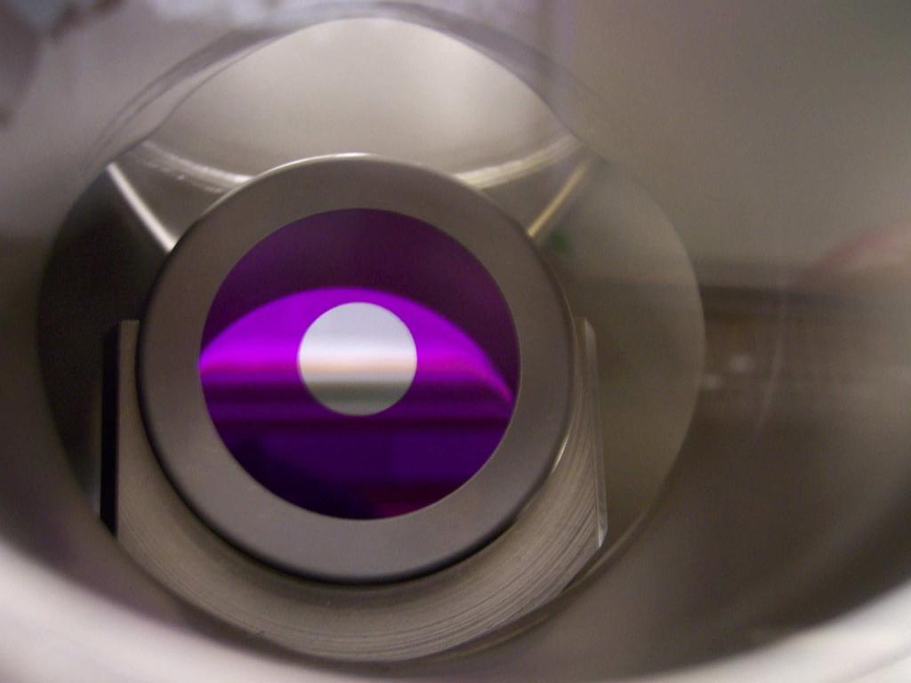
10 dump Cornell Injector prototype: Verification of beam production diagnostics SC injector gun Power sup. Cathode Photo emitter gun
11 Cornell Injector prototype: Diagnostics Faraday cup View screens, BPMs Flaying wire Quadrant detector Fast current detector Faraday cup Two slit emittance measurement View screens BPMs


12 Emittance Measurement System Fixed slits Corrector coils for beam scanning 10 micron precision slits 1 kw beam power handling Measured phase space Low charge Courtesy Ivan Bazarov data astra Highest current: 25mA Highest voltage: 430kV Highest bunch charge: 80pC Highest Q.E.: 14% 77pC 77pC Good agreement with Astra calculation for a misaligned solenoid.
13 (1) Comparison to HIGH POWER ERL-FELs Production of low emittances Space charge compensation in the injector less critical by >10 Diagnostics needs Phase space measurement for injector setup still important Laser diagnostics for bunch position and bunch timing feedback - still relevant Laser diagnostics for transverse and longitudinal profile - less critical
14 (2) Challenges for x-ray ERLs Limited emittance growth Beam stabilization to fraction of the very small beamsize Optics in the linac for very different energies (0.01-5GeV) Low emittance growth optics similar to light sources Limit optics errors and adjust fields to radiated energy Limit coupler kicks / cavity misalignments Diagnostics needs Sub micron BPMs Beam position measurements for two simultaneous beams High energy beam-size measurements High energy emittance measurements

15 Linear Optics
16 Incoherent Synchrotron Radiation (ISR) TA CE NA LA SA LB TS.SE.SSNAM#S.DDD#DC MA.SA.CELLB05.Qua03a CE NA LA TA LB LA TA LB SA

 Read out a difference orbit at 1.3GHz and a sum orbit at 2.6GHz. 2) Buttons: ok Strip line: size for 1/6 of the rf wavelength No Cavity BPM: would need a resonance at 1.3GHz and 2.")
17 5GeV ERL BPMs Upgrade for the Cornell for CESR ERL Challenges: 1) Two beams of different energy have to be measured simultaneously in much of the ERL 2) Tolerances of transverse motion are very stringent, 0.3mm in some places: 0.5mm m at 10kHz and <0.1mm m at 10Hz for 77pC, 1.3GHz. 3) Wake-field heating and energy spread from wake fields has to be tolerable 4) BPMs have to work in 80K environment, or use HOM bpms (< 4micron resolution, PRST-AB 9/112802) Possible solutions: 1) Read out a difference orbit at 1.3GHz and a sum orbit at 2.6GHz. 2) Buttons: ok Strip line: size for 1/6 of the rf wavelength No Cavity BPM: would need a resonance at 1.3GHz and 2.6GHz. Strategy: Use buttons all around the ring and strip lines at a few critical places for low currents, use HOMs
18 Button Beam Position Monitors Design: four 10mm buttons in a 25.4mm beampipe 1. Initial injection tune-up mode: 50MHz, 1ms bunch train, 2-10pC per bunch Resolution: +/- 20 4micron at 10kHz readout 2. Orbit refinement mode: 50MHz, 1ms bunch train, 10-77pC per bunch Resolution: +/ micron at 10kHz readout 3. Low current CW tune-up mode: 1300MHz, 1ms bunch train, 2-10pC per bunch Resolution: +/- 20 4micron at 10kHz readout 4. High current CW ramp-up mode: 1300MHz, 1ms bunch train, 10pC per bunch Resolution: +/- 4micron at 10kHz readout 5. High current CW ramp-up mode: 1300MHz, CW, 10-77pC per bunch Resolution: +/ micron at 10kHz readout 6. Stable ERL operational mode: 1300MHz, CW, 77pC Resolution: +/- 0.5micrometer at 10kHz readout at 0.1micron at 10Hz
19 Alignment requirements General comment about DC alignment requirements: These are similar to that in ring light sources because the vertical beam size in such sources is as small and smaller than the vertical and horizontal size in the ERL. Achieved orbit stability in 3 rd generation light sources: Horizontal Orbit Vertical Orbit

20 BPM and corrector placement The orbit can be controlled with the placement of BPMs and correctors. Uncorrected orbit for 0.3mm rms quadrupole misalignments: Corrected orbit for 0.3mm rms quadrupole misalignments:

21 Vibration measurements Bilderback Hartill
22 (2) Comparison to HIGH POWER ERL-FELs Limited emittance growth Beam stabilization to fraction of the very small beamsize - much less critical but probably much more vibrations Optics in the linac for very different energies (0.01-5GeV) - much less critical (approx MeV) Low emittance growth optics similar to light sources Limit optics errors and adjust fields to radiated energy Limit coupler kicks / cavity misalignments Diagnostics needs Sub micron BPMs Beam position measurements for two simultaneous beams High energy beam-size measurements High energy emittance measurements
23 (3) Challenges for x-ray ERLs Limit energy spread after deceleration, e.g. 5GeV to 10MeV Accurate time of flight correction, including sextupoles Limit energy spread from wake fields Limit energy spread from intra beam scattering (IBS) and rest gas scattering Limit energy spread from incoherent / coherent synchrotron radiation (ISR / CSR) Dumping a beam with very large energy spread Diagnostic needs Bunch arrival time diagnostics Halo diagnostics after deceleration (end of linac and dump) X-ray diagnostics for personal and electronics protection Dump diagnostics, based on beam loss
24 CSR in ERL bends Radiation from tail accelerates head Denser region radiates more p HmcL Phase spacewith HblueL, without HredL CSR For shorter bunches or for not optimized optics the energy spread becomes too large thpsl ELEGANT used here
25 Timing and Bunch Arrival Diagnostics Orbit length correction (to about 150mm): Master oscillator correction (slow) and dispersive bump correction (fast) State of the art: Electro optical sampling with a laser pulse in a birefringent medium co-propagating with electrons 30fs (e.g. Hacker et al., FEL06). State of the art: Timing signal propagation for bunch to RF synchronization < 10fs (e.g. Loehl et al., PAC07).

26 Scattering and background: IBS na µ µ µ µ element number na 4.µ µ µ µ element number Courtesy Sasha Temnykh
27 Radiation shielding Estimate following H.J. Moe in APS-LS-141 & -272 Arcs radius(m) length(m) North South Three contributions to background from continuous uniform e - loss: Bremsstrahlung, giant resonance neutrons, & high-energy neutrons For average beam loss 1 pa/m over 205m southern arc, shield wall: for 2 heavy concrete + 2 Pb 0.058mrem/hr just outside the wall, at arc center. Moe s estimate for APS (300mA,10 hour lifetime or 1/57 pa/m) 80cm normal concrete wall limits dose to 8 50m Public: limit to less than 100mrem/year, occupational limit to less than 5000mrem/year
28 (3) Comparison to HIGH POWER ERL-FELs Limit energy spread after deceleration, e.g. 5GeV to 10MeV Accurate time of flight correction, including sextupoles more severe Limit energy spread from wake fields less severe (less deceleration) Limit energy spread from intra beam scattering (IBS) and rest gas scattering less severe (less deceleration) Limit energy spread from incoherent / coherent synchrotron radiation (ISR / CSR) much more severe due to FEL induced spread Dumping a beam with very large energy spread Diagnostic needs Bunch arrival time diagnostics - similar Halo diagnostics probably more severe (FEL energy spread) X-ray diagnostics for personal and electronics protection similar Dump diagnostics based on beamloss 4 times worse and larger
29 (4) Challenges for x-ray ERLs Beam loss concerns Disturbance from ions / ion removal Halo development Component failures and machine protection system Diagnostics Ion composition monitor Halo detectors Beam Loss monitors (e.g. fiber BLMs, W. Goettmann et al., DIPAC05)
30 Ion focusing Ion are quickly produced due to high beam density Ion accumulate in the beam potential. Since the beam is very narrow, ions produce an extremely steep potential they have to be eliminated. Conventional ion clearing techniques: 1) Long clearing gaps have transient RF effects in the ERL [2ms every 7ms]. 2) Short gaps have transient effects in injector and gun and produce more beam harmonics that excite HOMs [0.4 ms every 7ms]. 3) DC fields of about 150kV/m have to be applied to appropriate places of the along the accelerator, without disturbing the electron beam. But remnant ion density before clearing can still cause emittance growth.
31 r (a.u.) Ions in an ERL beam X (mrad) x (s) 10/6 0-10/ x (s) -20/6-30/6 100m between clearing fields x (mm)
32 r (a.u.) Ions in an ERL beam X (mrad) x (s) X (mrad) 40/6 0-40/6-80/ x (s) 10/6 0-10/6-20/6-30/6 100m between clearing fields x (mm) 20m between clearing fields x (mm)
 2 0-40/6-2 -80/6-4 20m between clearing fields realistically placed ion clearing -0.4-0.3-0.2-0.1 0 0.1 0.2 x (mm) -0.1-0.05 0 0.05 0.1 x(mm)")
33 r (a.u.) Ions in an ERL beam X (mrad) x (s) X (mrad) 40/ x (s) 10/6 0-10/6-20/6 X (mrad) -30/6 100m between clearing fields x (mm) / /6-4 20m between clearing fields realistically placed ion clearing x (mm) x(mm)


34 Ions concentration diagnostics Ionization of Residual Gas Particles by Electron Beam Creates Ion Column Problems Introduced by Ions: 1. Distortion of Accelerator Optics 2. Coupled Oscillations Between Beam and Ions
35 (4) Comparison to HIGH POWER ERL-FELs Beam loss concerns Disturbance from ions / ion removal - less severe (less cross section, more gap between bunches) Halo development - similar significance before undulator - more significant after undulator Component failures and machine protection system - similar for electron beam, more severe for photon beam Diagnostics Ion composition monitor Halo detectors more severe after undulator Beam Loss Monitors (e.g. fiber BLMs, W. Goettmann et al., DIPAC05) - similar
36 (5) Challenges for x-ray ERLs Superconducting RF challenges Phase and amplitude control for very narrow frequency window (10-8 ) in the presence of microphonics Avoid heating / Higher order mode absorption Limit cooling power Diagnostics Cavity field diagnostics, input coupler diagnostics Thermometry, HOM-power diagnostics Cryogenic diagnostics Microphonics diagnostics, e.g. Piezo electric

37 Beam instabilities collaboration with JLAB Beam breakup instability (BBU) can limit the current in an ERL to below 100mA Experiments with JLAB: BBU is well understood for the 3 ma threshold current.
![cavity field [arb. units] 1 Cavity control for SC linacs (ERL & ILC) 13 Hz bandwidth 0-1000 -500 0 500 1000 Frequency 1.](/docs-images/72/66835023/images/38-0.jpg "3 GHz [Hz] Run cavity with lowest possible bandwidth for ERL. But frequency stabilization becomes very critical.")
38 cavity field [arb. units] 1 Cavity control for SC linacs (ERL & ILC) 13 Hz bandwidth Frequency 1.3 GHz [Hz] Run cavity with lowest possible bandwidth for ERL. But frequency stabilization becomes very critical. accelerating field [MV/m] phase [deg] Without feedback: 0 0 time [sec] 1 0 time [sec] 1 Courtesy Matthias Liepe
39 Cavity control for SC linacs (ERL & ILC) cavity field [arb. units] 1 0 For strong fields frequency 1.3 GHz [Hz] Run cavity with lowest possible bandwidth for ERL. But frequency stabilization becomes very critical. accelerating field [MV/m] phase [deg] Without feedback: 0 0 time [sec] 1 0 time [sec] 1 Courtesy Matthias Liepe
40 cavity field [arb. units] 1 0 Cavity control for SC linacs (ERL & ILC) Add Microphonics! (Hz) frequency 1.3 GHz Run cavity with lowest possible bandwidth for ERL. But frequency stabilization becomes very critical. accelerating field [MV/m] phase [deg] Without feedback: 0 0 time [sec] 1 0 time [sec] 1 Courtesy Matthias Liepe
41 Cavity control for SC linacs (ERL & ILC) cavity field [arb. units] 1 0 Add Controls! frequency 1.3 GHz [Hz] Run cavity with lowest possible bandwidth for ERL. But frequency stabilization becomes very critical. accelerating field [MV/m] phase [deg] With feedback: σ A /A time [sec] σ ϕ 0.02 deg Vibration time [sec] Mode Courtesy Matthias Liepe
42 (5) Comparison to HIGH POWER ERL-FELs Superconducting RF challenges Phase and amplitude control for very narrow frequency window (10-8 ) in the presence of microphonics more microphonics Avoid heating / Higher order mode absorption - more significant (denser bunch spectrum) Limit cooling power similar Diagnostics Cavity field diagnostics, input coupler diagnostics - similar Thermometry, HOM-power diagnostics - similar Cryogenic diagnostics - similar Microphonics diagnostics, e.g. Piezo electric even more relevant
WG2 on ERL light sources CHESS & LEPP
 Charge: WG2 on ERL light sources Address and try to answer a list of critical questions for ERL light sources. Session leaders can approach each question by means of (a) (Very) short presentations (b)
Optics considerations for
 Optics considerations for ERL x-ray x sources Georg H. Hoffstaetter* Physics Department Cornell University Ithaca / NY Georg.Hoffstaetter@cornell.edu 1. Overview of Parameters 2. Critical Topics 3. Phase
X-ray applications and accelerator physics for the Cornell ERL
 1 X-ray applications and accelerator physics for the Cornell ERL Georg H. Hoffstaetter Cornell Physics Dep. / 6 3 7 1 4 8 2 5 2 Overview Principle and history of ERLs How good of an X-ray source could
Toward an Energy Recovery Linac x-ray source at Cornell University
 1 Toward an Energy Recovery Linac x-ray source at Cornell University Georg Hoffstaetter Cornell Physics Dept. / LEPP The ERL principle Limits of ERLs Studies for an x-ray ERL Ivan Bazarov LEPP / CHESS
Overview of Energy Recovery Linacs
 Overview of Energy Recovery Linacs Ivan Bazarov Cornell High Energy Synchrotron Source Talk Outline: Historical Perspective Parameter Space Operational ERLs & Funded Projects Challenges ERL Concept: conventional
ERL upgrade of an existing X-ray facility: CHESS at CESR
 ERL-5-8 ERL upgrade of an existing X-ray facility: CHESS at CESR G.H. Hoffstaetter Abstract Cornell University has proposed an Energy-Recovery Linac (ERL) based synchrotron-light facility which uses 5GeV,
Accelerator Physics Issues of ERL Prototype
 Accelerator Physics Issues of ERL Prototype Ivan Bazarov, Geoffrey Krafft Cornell University TJNAF ERL site visit (Mar 7-8, ) Part I (Bazarov). Optics. Space Charge Emittance Compensation in the Injector
Georg Hoffstaetter Cornell Physics Dept. / CLASSE Cornell s ERL team
 1 R&D toward an ERL Georg Hoffstaetter Cornell Physics Dept. / Cornell s ERL team DC-gun R&D CW linac R&D SRF injector R&D Undulator R&D 2 Cornell history: The ERL principle Energy recovery needs continuously
SLS at the Paul Scherrer Institute (PSI), Villigen, Switzerland
, Villigen, Switzerland") SLS at the Paul Scherrer Institute (PSI), Villigen, Switzerland Michael Böge 1 SLS Team at PSI Michael Böge 2 Layout of the SLS Linac, Transferlines Booster Storage Ring (SR) Beamlines and Insertion Devices
SLS at the Paul Scherrer Institute (PSI), Villigen, Switzerland Michael Böge 1 SLS Team at PSI Michael Böge 2 Layout of the SLS Linac, Transferlines Booster Storage Ring (SR) Beamlines and Insertion Devices
Charge for WG2 (Optics and Beams)
") Charge for WG2 (Optics and Beams) Georg H. Hoffstaetter (Cornell University / Physics) on behalf of the conveners of WG2: Vladimir Litvinenko (BNL / Accelerator Physics) Hywel Owen (Daresbury / ASTeC)
Charge for WG2 (Optics and Beams) Georg H. Hoffstaetter (Cornell University / Physics) on behalf of the conveners of WG2: Vladimir Litvinenko (BNL / Accelerator Physics) Hywel Owen (Daresbury / ASTeC)
Diagnostic Systems for Characterizing Electron Sources at the Photo Injector Test Facility at DESY, Zeuthen site
 1 Diagnostic Systems for Characterizing Electron Sources at the Photo Injector Test Facility at DESY, Zeuthen site Sakhorn Rimjaem (on behalf of the PITZ team) Motivation Photo Injector Test Facility at
New Electron Source for Energy Recovery Linacs
 New Electron Source for Energy Recovery Linacs Ivan Bazarov 20m Cornell s photoinjector: world s brightest electron source 1 Outline Uses of high brightness electron beams Physics of brightness High brightness
4GLS Status. Susan L Smith ASTeC Daresbury Laboratory
 4GLS Status Susan L Smith ASTeC Daresbury Laboratory Contents ERLP Introduction Status (Kit on site ) Plan 4GLS (Conceptual Design) Concept Beam transport Injectors SC RF FELs Combining Sources May 2006
BERLinPro. An ERL Demonstration facility at the HELMHOLTZ ZENTRUM BERLIN
 BERLinPro An ERL Demonstration facility at the HELMHOLTZ ZENTRUM BERLIN BERLinPro: ERL demonstration facility to prepare the ground for a few GeV ERL @ Berlin-Adlershof Goal: 100MeV, 100mA beam Small emittance,
Lattice Design and Performance for PEP-X Light Source
 Lattice Design and Performance for PEP-X Light Source Yuri Nosochkov SLAC National Accelerator Laboratory With contributions by M-H. Wang, Y. Cai, X. Huang, K. Bane 48th ICFA Advanced Beam Dynamics Workshop
X-band RF driven hard X-ray FELs. Yipeng Sun ICFA Workshop on Future Light Sources March 5-9, 2012
 X-band RF driven hard X-ray FELs Yipeng Sun ICFA Workshop on Future Light Sources March 5-9, 2012 Motivations & Contents Motivations Develop more compact (hopefully cheaper) FEL drivers, L S C X-band (successful
The TESLA Dogbone Damping Ring
 The TESLA Dogbone Damping Ring Winfried Decking for the TESLA Collaboration April 6 th 2004 Outline The Dogbone Issues: Kicker Design Dynamic Aperture Emittance Dilution due to Stray-Fields Collective
Comparison of the APS Upgrade to
 Comparison of the APS Upgrade to ERL@APS Michael Borland Argonne National Laboratory March 2010 The submitted manuscript has been created by UChicago Argonne, LLC, Operator of Argonne National Laboratory
Status of Proof-of-Principle Experiment of Coherent Electron Cooling at BNL
 Status of Proof-of-Principle Experiment of Coherent Electron Cooling at BNL Outline 2 Why we doing it? What is Coherent electron Cooling System description Subsystem performance Plan for Run 18 e-n Luminosity
Operational Experience with HERA
 PAC 07, Albuquerque, NM, June 27, 2007 Operational Experience with HERA Joachim Keil / DESY On behalf of the HERA team Contents Introduction HERA II Luminosity Production Experiences with HERA Persistent
An ERL-Based High-Power Free- Electron Laser for EUV Lithography
 An ERL-Based High-Power Free- Electron Laser for EUV Lithography Norio Nakamura High Energy Accelerator Research Organization(KEK) 2015 EUVL Workshop, Maui, Hawaii, USA, June 15-19, 2015. ERL-EUV Design
Low Energy RHIC electron Cooling (LEReC)
") Low Energy RHIC electron Cooling (LEReC) LEReC overview: project goal and cooling approach Alexei Fedotov MEIC Collaboration Meeting 30 31 LEReC Project Mission/Purpose The purpose of the LEReC is to provide
Low Energy RHIC electron Cooling (LEReC) LEReC overview: project goal and cooling approach Alexei Fedotov MEIC Collaboration Meeting 30 31 LEReC Project Mission/Purpose The purpose of the LEReC is to provide
A Review of ERL Prototype Experience and Light Source Design Challenges. Susan Smith Accelerator Physics ASTeC CCLRC Daresbury Laboratory
 A Review of ERL Prototype Experience and Light Source Design Challenges Susan Smith Accelerator Physics ASTeC CCLRC Daresbury Laboratory Content Existing light source ERLs JLAB experience Challenges of
Developments for Cornell's X Ray ERL
 Particle Accelerator Conference May 4 8, 2009 Vancouver, Canada Developments for Cornell's X Ray ERL J.A. Crittenden CLASSE, Cornell University 4 May 2009 TA LA CE NA LB SA TB Performance of an ERL Based
Cornell Injector Performance
 Cornell Injector Performance Adam Bartnik 1 Cornell Injector Performance as an ERL injector 2 Cornell Injector Performance as an ERL injector as an FEL injector (e.g. LCLS-II) as an injector for EIC applications
2.6 Electron transport lines
 2.6 Electron transport lines 2.6 Electron transport lines Overview The electron transport lines consist of all of the electron beamline segments that are neither part of the Linacs nor part of the injector.
Status of linear collider designs:
 Status of linear collider designs: Main linacs Design overview, principal open issues G. Dugan March 11, 2002 Linear colliders: main linacs The main linac is the heart of the linear collider TESLA, NLC/JLC,
Accelerator Physics. Accelerator Development
 Accelerator Physics The Taiwan Light Source (TLS) is the first large accelerator project in Taiwan. The goal was to build a high performance accelerator which provides a powerful and versatile light source
Low slice emittance preservation during bunch compression
 Low slice emittance preservation during bunch compression S. Bettoni M. Aiba, B. Beutner, M. Pedrozzi, E. Prat, S. Reiche, T. Schietinger Outline. Introduction. Experimental studies a. Measurement procedure
ThomX Machine Advisory Committee. (LAL Orsay, March ) Ring Beam Dynamics
 Ring Beam Dynamics") ThomX Machine Advisory Committee (LAL Orsay, March 20-21 2017) Ring Beam Dynamics A. Loulergue, M. Biagini, C. Bruni, I. Chaikovska I. Debrot, N. Delerue, A. Gamelin, H. Guler, J. Zang Programme Investissements
ThomX Machine Advisory Committee (LAL Orsay, March 20-21 2017) Ring Beam Dynamics A. Loulergue, M. Biagini, C. Bruni, I. Chaikovska I. Debrot, N. Delerue, A. Gamelin, H. Guler, J. Zang Programme Investissements
7th IPAC, May 8-13, 2016, Busan, Korea
 7th IPAC, May 8-13, 2016, Busan, Korea ER@CEBAF A High-Energy, Multiple-Pass, Energy Recovery Experiment at CEBAF On behalf of the JLab-BNL ER@CEBAF collaboration : I. Ben-Zvi, Y. Hao, P. Korysko, C. Liu,
INITIAL BEAM RESULTS FROM THE CORNELL HIGH-CURRENT ERL INJECTOR PROTOTYPE
 INITIAL BEAM RESULTS FROM THE CORNELL HIGH-CURRENT ERL INJECTOR PROTOTYPE I. Bazarov, S. Belomestnykh, E. Chojnacki, J. Dobbins, B. Dunham, R. Ehrlich, M. Forster, C. Gulliford, G. Hoffstaetter, H. Li,
USPAS Course on Recirculating Linear Accelerators
 USPAS Course on Recirculating Linear Accelerators G. A. Krafft and L. Merminga Jefferson Lab Lecture 4 Outline Independent Orbit Recirculators The Stanford-HEPL Superconducting Recyclotron Basic Design
Linac optimisation for the New Light Source
 Linac optimisation for the New Light Source NLS source requirements Electron beam requirements for seeded cascade harmonic generation LINAC optimisation (2BC vs 3 BC) CSR issues energy chirp issues jitter
Excitements and Challenges for Future Light Sources Based on X-Ray FELs
 Excitements and Challenges for Future Light Sources Based on X-Ray FELs 26th ADVANCED ICFA BEAM DYNAMICS WORKSHOP ON NANOMETRE-SIZE COLLIDING BEAMS Kwang-Je Kim Argonne National Laboratory and The University
LCLS Accelerator Parameters and Tolerances for Low Charge Operations
 LCLS-TN-99-3 May 3, 1999 LCLS Accelerator Parameters and Tolerances for Low Charge Operations P. Emma SLAC 1 Introduction An option to control the X-ray FEL output power of the LCLS [1] by reducing the
Linacs. Susan Smith. Daresbury Laboratory Mami and Beyond
 Energy Recovery Linacs Susan Smith ASTeC/Cockcroft Daresbury Laboratory Mami and Beyond Introduction to ERLs Contents Operational ERLs Applications Challenges ERL Prototypes and R&D Summary 2 Introduction
First propositions of a lattice for the future upgrade of SOLEIL. A. Nadji On behalf of the Accelerators and Engineering Division
 First propositions of a lattice for the future upgrade of SOLEIL A. Nadji On behalf of the Accelerators and Engineering Division 1 SOLEIL : A 3 rd generation synchrotron light source 29 beamlines operational
ELIC Design. Center for Advanced Studies of Accelerators. Jefferson Lab. Second Electron-Ion Collider Workshop Jefferson Lab March 15-17, 2004
 ELIC Design Ya. Derbenev, K. Beard, S. Chattopadhyay, J. Delayen, J. Grames, A. Hutton, G. Krafft, R. Li, L. Merminga, M. Poelker, E. Pozdeyev, B. Yunn, Y. Zhang Center for Advanced Studies of Accelerators
Issues of Electron Cooling
 Issues of Electron Cooling Yaroslav Derbenev derbenev@jlab.org JLEIC Spring 2016 Collaboration Meeting JLab, March 29-31, 2016 Outline Friction force Magnetized cooling Misalignment impact Cooling rates
Linac Ring Colliders
 Linac Ring Colliders L. Merminga and G. Krafft, Jefferson Lab V. Lebedev, FNAL and I. Ben-Zvi, BNL The Future of Particle Physics Snowmass 2001 July 4 2001, Snowmass Village, CO Outline ΠPhysics Requirements
Using IMPACT T to perform an optimization of a DC gun system Including merger
 Using IMPACT T to perform an optimization of a DC gun system Including merger Xiaowei Dong and Michael Borland Argonne National Laboratory Presented at ERL09 workshop June 10th, 2009 Introduction An energy
Excitements and Challenges for Future Light Sources Based on X-Ray FELs
 Excitements and Challenges for Future Light Sources Based on X-Ray FELs 26th ADVANCED ICFA BEAM DYNAMICS WORKSHOP ON NANOMETRE-SIZE COLLIDING BEAMS Kwang-Je Kim Argonne National Laboratory and The University
Diagnostics at the MAX IV 3 GeV storage ring during commissioning. PPT-mall 2. Åke Andersson On behalf of the MAX IV team
 Diagnostics at the MAX IV 3 GeV storage ring during commissioning PPT-mall 2 Åke Andersson On behalf of the MAX IV team IBIC Med 2016, linje Barcelona Outline MAX IV facility overview Linac injector mode
Review of proposals of ERL injector cryomodules. S. Belomestnykh
 Review of proposals of ERL injector cryomodules S. Belomestnykh ERL 2005 JLab, March 22, 2005 Introduction In this presentation we will review injector cryomodule designs either already existing or under
OVERVIEW OF ENERGY RECOVERY LINACS
 OVERVIEW OF ENERGY RECOVERY LINACS Ivan V. Bazarov, LEPP/CHESS, Cornell University, Ithaca, NY 14853, USA Abstract Existing Energy Recovery Linacs (ERLs) are successfully operated as kw-class average power
S2E (Start-to-End) Simulations for PAL-FEL. Eun-San Kim
 Simulations for PAL-FEL. Eun-San Kim") S2E (Start-to-End) Simulations for PAL-FEL Aug. 25 2008 Kyungpook Nat l Univ. Eun-San Kim 1 Contents I Lattice and layout for a 10 GeV linac II Beam parameters and distributions III Pulse-to-pulse stability
S2E (Start-to-End) Simulations for PAL-FEL Aug. 25 2008 Kyungpook Nat l Univ. Eun-San Kim 1 Contents I Lattice and layout for a 10 GeV linac II Beam parameters and distributions III Pulse-to-pulse stability
Short Pulse, Low charge Operation of the LCLS. Josef Frisch for the LCLS Commissioning Team
 Short Pulse, Low charge Operation of the LCLS Josef Frisch for the LCLS Commissioning Team 1 Normal LCLS Parameters First Lasing in April 10, 2009 Beam to AMO experiment August 18 2009. Expect first user
ERL FACILITY AT CERN FOR APPLICATIONS
 ERL FACILITY AT CERN FOR APPLICATIONS Erk Jensen (CERN) Big thanks to contributors: A. Bogacz (JLAB), O. Brüning, R. Calaga, V. Chetvertkova, E. Cormier (CELIA), R. Jones, M. Klein, A. Valloni, D. Pellegrini,
FURTHER UNDERSTANDING THE LCLS INJECTOR EMITTANCE*
 Proceedings of FEL014, Basel, Switzerland FURTHER UNDERSTANDING THE LCLS INJECTOR EMITTANCE* F. Zhou, K. Bane, Y. Ding, Z. Huang, and H. Loos, SLAC, Menlo Park, CA 9405, USA Abstract Coherent optical transition
Energy Recovery Linac (ERL) Science Workshop
 Science Workshop") Energy Recovery Linac (ERL) Science Workshop Sol M. Gruner, CHESS & Physics Dept. Objective: Examine science possible with an ERL x-ray source. Ques.: Ans.: Why do this? Need for more and better SR machines.
Energy Recovery Linac (ERL) Science Workshop Sol M. Gruner, CHESS & Physics Dept. Objective: Examine science possible with an ERL x-ray source. Ques.: Ans.: Why do this? Need for more and better SR machines.
PAL LINAC UPGRADE FOR A 1-3 Å XFEL
 PAL LINAC UPGRADE FOR A 1-3 Å XFEL J. S. Oh, W. Namkung, Pohang Accelerator Laboratory, POSTECH, Pohang 790-784, Korea Y. Kim, Deutsches Elektronen-Synchrotron DESY, D-603 Hamburg, Germany Abstract With
Linac Driven Free Electron Lasers (III)
") Linac Driven Free Electron Lasers (III) Massimo.Ferrario@lnf.infn.it SASE FEL Electron Beam Requirements: High Brightness B n ( ) 1+ K 2 2 " MIN r #$ % &B! B n 2 n K 2 minimum radiation wavelength energy
Linac Driven Free Electron Lasers (III) Massimo.Ferrario@lnf.infn.it SASE FEL Electron Beam Requirements: High Brightness B n ( ) 1+ K 2 2 " MIN r #$ % &B! B n 2 n K 2 minimum radiation wavelength energy
FACET-II Design Update
 FACET-II Design Update October 17-19, 2016, SLAC National Accelerator Laboratory Glen White FACET-II CD-2/3A Director s Review, August 9, 2016 Planning for FACET-II as a Community Resource FACET-II Photo
III. CesrTA Configuration and Optics for Ultra-Low Emittance David Rice Cornell Laboratory for Accelerator-Based Sciences and Education
 III. CesrTA Configuration and Optics for Ultra-Low Emittance David Rice Cornell Laboratory for Accelerator-Based Sciences and Education Introduction Outline CESR Overview CESR Layout Injector Wigglers
LCLS Injector Prototyping at the GTF
 LCLS Injector Prototyping at at the GTF John John Schmerge, SLAC SLAC November 3, 3, 23 23 GTF GTF Description Summary of of Previous Measurements Longitudinal Emittance Transverse Emittance Active LCLS
Superconducting RF Accelerators: Why all the interest?
 Superconducting RF Accelerators: Why all the interest? William A. Barletta Director, United States Particle Accelerator School Dept. of Physics, MIT The HEP prespective ILC PROJECT X Why do we need RF
HIGH CURRENT AND HIGH BRIGHTNESS ELECTRON SOURCES
 HIGH CURRENT AND HIGH BRIGHTNESS ELECTRON SOURCES F. Loehl, I. Bazarov, S. Belomestnykh, M. Billing, E. Chojnacki, Z. Conway, J. Dobbins, B. Dunham, R. Ehrlich, M. Forster, S. M. Gruner, C. Gulliford,
Femto second X ray Pulse Generation by Electron Beam Slicing. F. Willeke, L.H. Yu, NSLSII, BNL, Upton, NY 11973, USA
 Femto second X ray Pulse Generation by Electron Beam Slicing F. Willeke, L.H. Yu, NSLSII, BNL, Upton, NY 11973, USA r 2 r 1 y d x z v Basic Idea: When short electron bunch from linac (5MeV, 50pC,100fs)
SRF GUN CHARACTERIZATION - PHASE SPACE AND DARK CURRENT MEASUREMENTS AT ELBE*
 SRF GUN CHARACTERIZATION - PHASE SPACE AND DARK CURRENT MEASUREMENTS AT ELBE* E. Panofski #, A. Jankowiak, T. Kamps, Helmholtz-Zentrum Berlin, Berlin, Germany P.N. Lu, J. Teichert, Helmholtz-Zentrum Dresden-Rossendorf,
Status of Cornell s ERL Project
 1 Status of Cornell s ERL Project Georg Hoffstaetter, Professor Cornell University / / SRF group & ERL effort a) Vision for the Future b) Developments since ERL workshop at Cornell in June 2009 c) Planned
Accelerator R&D Opportunities: Sources and Linac. Developing expertise. D. Rubin, Cornell University
 Accelerator R&D Opportunities: Sources and Linac D. Rubin, Cornell University Electron and positron sources Requirements Status of R&D Linac Modeling of beam dynamics Development of diagnostic and tuning
On-axis injection into small dynamic aperture
 On-axis injection into small dynamic aperture L. Emery Accelerator Systems Division Argonne National Laboratory Future Light Source Workshop 2010 Tuesday March 2nd, 2010 On-Axis (Swap-Out) injection for
Pol. e + source based on Compton scattering with FEL & 4 mirror cavity 第 8 回全体打合せ, 30 September 2014 KEK, Junji Urakawa
 Pol. e + source based on Compton scattering with FEL & 4 mirror cavity 第 8 回全体打合せ, 30 September 2014 KEK, Junji Urakawa Super conducting electron linear accelerator for FEL We assume super radiant mode
6 Bunch Compressor and Transfer to Main Linac
 II-159 6 Bunch Compressor and Transfer to Main Linac 6.1 Introduction The equilibrium bunch length in the damping ring (DR) is 6 mm, too long by an order of magnitude for optimum collider performance (σ
Energy Recovery Linac (ERL) Properties. Physics Dept. & Cornell High Energy Synchrotron Source (CHESS) Ithaca, NY Cornell University
 Properties. Physics Dept. & Cornell High Energy Synchrotron Source (CHESS) Ithaca, NY Cornell University") Energy Recovery Linac (ERL) Properties Sol M. Gruner Physics Dept. & Cornell High Energy Synchrotron Source (CHESS) Cornell University Ithaca, NY 14853-2501 Acknowledgements T. Allen (Special thanks to
Energy Recovery Linac (ERL) Properties Sol M. Gruner Physics Dept. & Cornell High Energy Synchrotron Source (CHESS) Cornell University Ithaca, NY 14853-2501 Acknowledgements T. Allen (Special thanks to
FACET-II Design, Parameters and Capabilities
 FACET-II Design, Parameters and Capabilities 217 FACET-II Science Workshop, October 17-2, 217 Glen White Overview Machine design overview Electron systems Injector, Linac & Bunch compressors, Sector 2
SPPS: The SLAC Linac Bunch Compressor and Its Relevance to LCLS
 LCLS Technical Advisory Committee December 10-11, 2001. SPPS: The SLAC Linac Bunch Compressor and Its Relevance to LCLS Patrick Krejcik LCLS Technical Advisory Committee Report 1: July 14-15, 1999 The
The New Superconducting RF Photoinjector a High-Average Current & High-Brightness Gun
 The New Superconducting RF Photoinjector a High-Average Current & High-Brightness Gun Jochen Teichert for the BESSY-DESY-FZD-MBI collaboration and the ELBE crew High-Power Workshop, UCLA, Los Angeles 14
ICFA ERL Workshop Jefferson Laboratory March 19-23, 2005 Working Group 1 summary Ilan Ben-Zvi & Ivan Bazarov
 ICFA ERL Workshop Jefferson Laboratory March 19-23, 2005 Working Group 1 summary Ilan Ben-Zvi & Ivan Bazarov Sincere thanks to all WG1 participants: Largest group, very active participation. This summary
Applications of High Brightness Beams: Energy Recovered Linacs
 Applications of High Brightness Beams: Energy Recovered Linacs G. A. Krafft Jefferson Lab Schematic Representation of Accelerator Types RF Installation Beam injector and dump Beamline Ring Linac Recirculating
Towards a Low Emittance X-ray FEL at PSI
 Towards a Low Emittance X-ray FEL at PSI A. Adelmann, A. Anghel, R.J. Bakker, M. Dehler, R. Ganter, C. Gough, S. Ivkovic, F. Jenni, C. Kraus, S.C. Leemann, A. Oppelt, F. Le Pimpec, K. Li, P. Ming, B. Oswald,
USPAS course on Recirculated and Energy Recovered Linacs Ivan Bazarov, Cornell University Geoff Krafft, JLAB. Ongoing ERL R&D Cornell
 USPAS course on Recirculated and Energy Recovered Linacs Ivan Bazarov, Cornell University Geoff Krafft, JLAB Ongoing ERL R&D Cornell Contents Challenges Cornell ERL prototype Experimental program January
STATUS OF THE NOVOSIBIRSK ENERGY RECOVERY LINAC
 STATUS OF THE NOVOSIBIRSK ENERGY RECOVERY LINAC V.P. Bolotin, N.A. Vinokurov, N.G. Gavrilov, D.A. Kayran, B.A. Knyazev, E.I. Kolobanov, V. V. Kotenkov, V.V. Kubarev, G.N. Kulipanov, A.N. Matveenko, L.E.
(M. Bowler, C. Gerth, F. Hannon, H. Owen, B. Shepherd, S. Smith, N. Thompson, E. Wooldridge, N. Wyles)
") Optics considerations for ERL test facilities Bruno Muratori ASTeC Daresbury Laboratory (M. Bowler, C. Gerth, F. Hannon, H. Owen, B. Shepherd, S. Smith, N. Thompson, E. Wooldridge, N. Wyles) Overview Optics
Optics considerations for ERL test facilities Bruno Muratori ASTeC Daresbury Laboratory (M. Bowler, C. Gerth, F. Hannon, H. Owen, B. Shepherd, S. Smith, N. Thompson, E. Wooldridge, N. Wyles) Overview Optics
Emittance preservation in TESLA
 Emittance preservation in TESLA R.Brinkmann Deutsches Elektronen-Synchrotron DESY,Hamburg, Germany V.Tsakanov Yerevan Physics Institute/CANDLE, Yerevan, Armenia The main approaches to the emittance preservation
Future Light Sources March 5-9, 2012 Low- alpha mode at SOLEIL 1
 Introduction: bunch length measurements Reminder of optics Non- linear dynamics Low- alpha operation On the user side: THz and X- ray short bunch science CSR measurement and modeling Future Light Sources
Longitudinal Top-up Injection for Small Aperture Storage Rings
 Longitudinal Top-up Injection for Small Aperture Storage Rings M. Aiba, M. Böge, Á. Saá Hernández, F. Marcellini and A. Streun Paul Scherrer Institut Introduction Lower and lower horizontal emittances
Ultra-Low Emittance Storage Ring. David L. Rubin December 22, 2011
 Ultra-Low Emittance Storage Ring David L. Rubin December 22, 2011 December 22, 2011 D. L. Rubin 2 Much of our research is focused on the production and physics of ultra-low emittance beams. Emittance is
Ion clearing in an ERL
 Ion clearing in an ERL Georg H. Hoffstaetter and Matthias Liepe Laboratory for Elementary Particle Physics, Cornell University, Ithaca/NY (USA) Abstract The rest-gas in the beam-pipe of a particle accelerator
Investigation of the Effect of Space Charge in the compact-energy Recovery Linac
 Investigation of the Effect of Space Charge in the compact-energy Recovery Linac Ji-Gwang Hwang and Eun-San Kim, Kyungpook National University. 1370 Sankyok-dong, Buk-ku, Daegu, 702-701, Korea Tsukasa
3. Synchrotrons. Synchrotron Basics
 1 3. Synchrotrons Synchrotron Basics What you will learn about 2 Overview of a Synchrotron Source Losing & Replenishing Electrons Storage Ring and Magnetic Lattice Synchrotron Radiation Flux, Brilliance
Generation and characterization of ultra-short electron and x-ray x pulses
 Generation and characterization of ultra-short electron and x-ray x pulses Zhirong Huang (SLAC) Compact XFEL workshop July 19-20, 2010, Shanghai, China Ultra-bright Promise of XFELs Ultra-fast LCLS Methods
ANALYSIS OF HIGH ORDER MODES IN 1.3 GHZ CW SRF ELECTRON LINAC FOR A LIGHT SOURCE
 ANALYSIS OF HIGH ORDER MODES IN 1.3 GHZ CW SRF ELECTRON LINAC FOR A LIGHT SOURCE A. Sukhanov, A. Vostrikov, V. Yakovlev, Fermilab, Batavia, IL 60510, USA Abstract Design of a Light Source (LS) based on
Lattice Design of 2-loop Compact ERL. High Energy Accelerator Research Organization, KEK Miho Shimada and Yukinori Kobayashi
 Lattice Design of 2-loop Compact ERL High Energy Accelerator Research Organization, KEK Miho Shimada and Yukinori Kobayashi Introduction Wepromote the construction of the compact Energy Recovery Linac(cERL)
e + e - Linear Collider
 e + e - Linear Collider Disclaimer This talk was lifted from an earlier version of a lecture by N.Walker Eckhard Elsen DESY DESY Summer Student Lecture 3 rd August 2006 1 Disclaimer II Talk is largely
Statusreport. Status of the GSI accelerators for FRS operation. Jens Stadlmann (FAIR Synchrotrons)
") Statusreport Status of the GSI accelerators for FRS operation Jens Stadlmann (FAIR Synchrotrons) Overview Intensities reached and "candidates" for experiments. Uranium? Upgrade program New developments:
Statusreport Status of the GSI accelerators for FRS operation Jens Stadlmann (FAIR Synchrotrons) Overview Intensities reached and "candidates" for experiments. Uranium? Upgrade program New developments:
ELIC: A High Luminosity And Efficient Spin Manipulation Electron-Light Ion Collider Based At CEBAF
 ELIC: A High Luminosity And Efficient Spin Manipulation Electron-Light Ion Collider Based At CEBAF Lia Merminga and Yaroslav Derbenev Center for Advanced Studies of Accelerators, Jefferson Laboratory,
Short Introduction to CLIC and CTF3, Technologies for Future Linear Colliders
 Short Introduction to CLIC and CTF3, Technologies for Future Linear Colliders Explanation of the Basic Principles and Goals Visit to the CTF3 Installation Roger Ruber Collider History p p hadron collider
Turn-by-Turn Beam Position Measurements at ANKA with LIBERA ELECTRON
 Turn-by-Turn Beam Position Measurements at ANKA with LIBERA ELECTRON E.Huttel, I.Birkel, A.S.Müller, P.Wesolowski About ANKA Test by Frequency Generator Experiences in the Booster Experiences in the Storage
Development status of non-destructive assay of nuclear material by using laser Compton scattered gamma-rays
 Development status of non-destructive assay of nuclear material by using laser Compton scattered gamma-rays Ryoichi Hajima Japan Atomic Energy Agency IZEST Tokyo 2013 Nov. 18, 2013 Collaborators Quantum
The MAX IV Thermionic preinjector
 The MAX IV Thermionic preinjector David Olsson ESLS RF, Lund, 2015-09-30 Injection Requirements I Full-energy injection from the LINAC 1.5 GeV and 3 GeV extraction points. Both storage rings will be operated
Update on Optics Modeling for the ATF Damping Ring at KEK Studies for low vertical emittance
 Update on Optics Modeling for the ATF Damping Ring at KEK Studies for low vertical emittance 2009.05.08. K. Kubo, S. Kuroda, T. Okugi (KEK) M.D. Woodley (SLAC), A. Wolski, K. Panagiotidis (U. Liverpool
THE LCLS-II INJECTOR DESIGN*
 THE LCLS-II INJECTOR DESIGN* J.F. Schmerge #, A. Brachmann, D. Dowell, A. Fry, R.K. Li, Z. Li, T. Raubenheimer, T. Vecchione, F. Zhou, SLAC, Menlo Park, CA 94025, USA A. Bartnik, I. Bazarov, B. Dunham,
SCSS Prototype Accelerator -- Its outline and achieved beam performance --
 SCSS Prototype Accelerator -- Its outline and achieved beam performance -- Hitoshi TANAKA RIKEN, XFEL Project Office 1 Content 1. Light Quality; SPring-8 v.s. XFEL 2. What are the critical issues? 3. Mission
Waseda University. Design of High Brightness Laser-Compton Light Source for EUV Lithography Research in Shorter Wavelength Region
 Waseda University Research Institute for Science and Engineering Design of High Brightness Laser-Compton Light Source for EUV Lithography Research in Shorter Wavelength Region Research Institute for Science
VELA/CLARA as Advanced Accelerator Studies Test-bed at Daresbury Lab.
 VELA/CLARA as Advanced Accelerator Studies Test-bed at Daresbury Lab. Yuri Saveliev on behalf of VELA and CLARA teams STFC, ASTeC, Cockcroft Institute Daresbury Lab., UK Outline VELA (Versatile Electron
Experimental Optimization of Electron Beams for Generating THz CTR and CDR with PITZ
 Experimental Optimization of Electron Beams for Generating THz CTR and CDR with PITZ Introduction Outline Optimization of Electron Beams Calculations of CTR/CDR Pulse Energy Summary & Outlook Prach Boonpornprasert
DIAGNOSTIC TEST-BEAM-LINE FOR THE MESA INJECTOR
 DIAGNOSTIC TEST-BEAM-LINE FOR THE MESA INJECTOR I.Alexander,K.Aulenbacher,V.Bechthold,B.Ledroit,C.Matejcek InstitutfürKernphysik,JohannesGutenberg-Universität,D-55099Mainz,Germany Abstract With the test-beam-line
The Status of the Energy Recovery Linac Source of Coherent Hard X-rays at Cornell University
 The Status of the Energy Recovery Linac Source of Coherent Hard X-rays at Cornell University DONALD H. BILDERBACK, CHARLES SINCLAIR, AND SOL M. GRUNER Cornell University, Ithaca, NY, USA Synchrotron radiation