Status of linear collider designs:
|
|
|
- Gyles Underwood
- 5 years ago
- Views:
Transcription
1 Status of linear collider designs: Main linacs Design overview, principal open issues G. Dugan March 11, 2002
2 Linear colliders: main linacs The main linac is the heart of the linear collider TESLA, NLC/JLC, and CLIC have chosen very different technical solutions for the main linac rf. The differences in rf technology profoundly influence the beam dynamics issues related to the dominant challenge for achieving luminosity, which is emittance preservation.
3 Linear colliders: main linacs 500 GeV CM Parameter TESLA NLC CLIC Initial energy (GeV) Rf frequency (GHz) Unloaded/loaded gradient (MV/m) 23.4/ /55 172/150 Active two-linac length (km) Number of rf cavities/length (m) 20592/ / /0.5 Total number of klystrons Klystron peak power (MW) Rf pulse length (ms) v g /c Unloaded Q ~8500 ~3600 Total AC power for linac rf (MW) Wall plug->rf efficiency (%) Rf->beam efficiency (%)
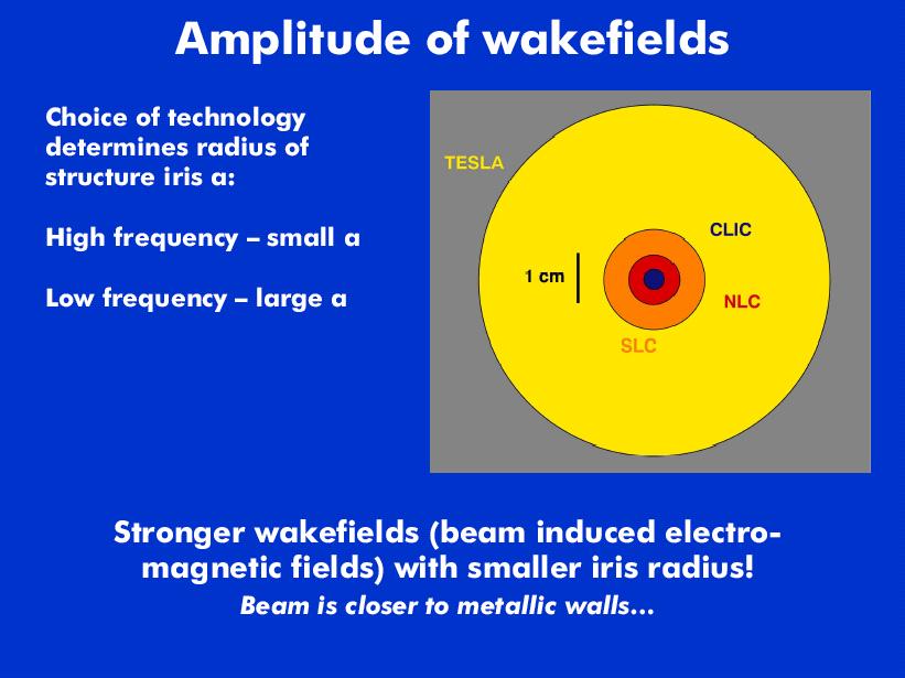
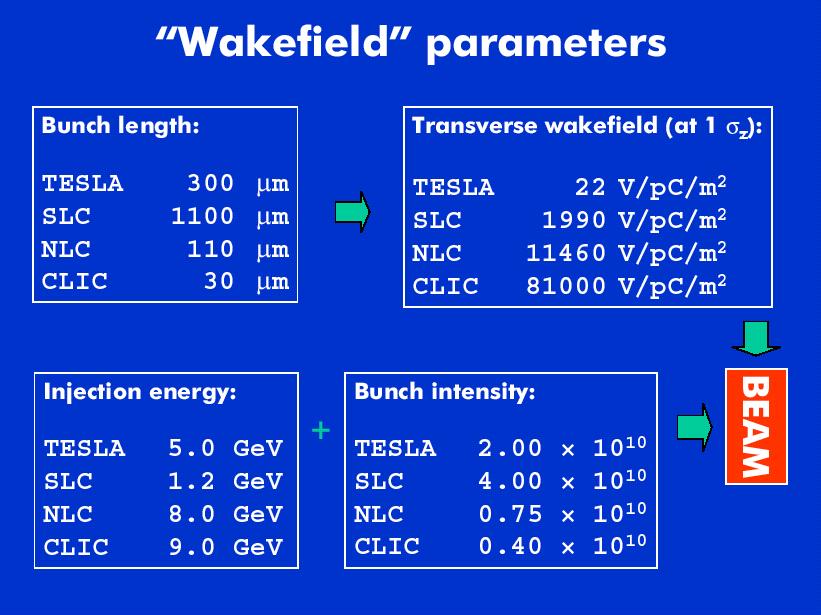
4 Main linacs-tesla-rf technology TESLA solution: low frequency (1.3 GHz) superconducting rf Pros: Low frequency, superconducting rf=>large iris radius (35 mm)=>low transverse wakefields (22 V/pC/m 2 )=>reduced alignment tolerances High rf->beam power conversion efficiency (62%) Rf power requirements modest ( MW peak power klystrons) Cons: Limited accelerating gradient (24 MV/m)=>longer linac for a given energy (11 km for 250 GeV) Extensive 2K cryogenic system required (scale of LHC) CM Energy upgrade goal: 800 GeV (35 MV/m 9-cell cavities+superstructures)
5
6
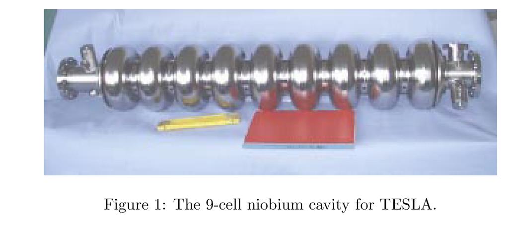
7 Twelve 9-cell cavitites per cryomodule
8
9
10 Superstructure concept: gains 6% in filling factor Number of power couplers reduced by 2
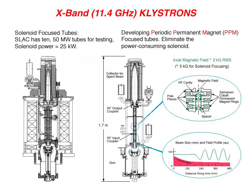
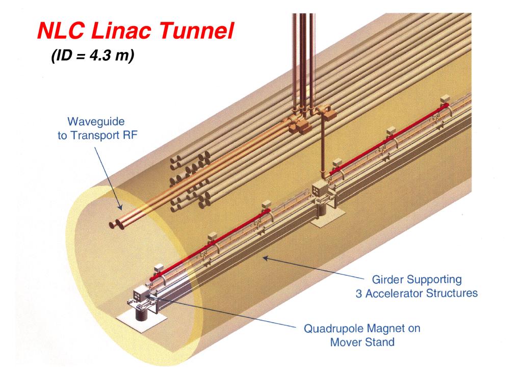
11 Main linacs-nlc/jlc-rf technology NLC/JLC solution: high frequency (11.4 GHz) normal conducting rf Pros: High accelerating gradient (55 MV/m)=>shorter linac for a given energy (6.8 km for 250 GeV) Cons: High frequency, normal conducting rf=>small iris radius (5 mm)=>high transverse wakefields (11, 500 V/pC/m 2 )=>tight alignment tolerances Low rf->beam power conversion efficiency (27%) Significant rf power requirements: MW klystrons (500 GeV)+pulse compression system CM energy upgrade goal: 1 TeV (2x12 km linacs)
12
13
14
15
16 NLC pulse distribution system
17
18
19 Main linacs:clic-rf technology CLIC solution: even higher frequency (30 GHz) normal conducting rf Pros: Very high accelerating gradient (150 MV/m)=>shorter linac for a given energy (2 km for 250 GeV) Cons: Very high frequency, normal conducting rf=>small iris radius (2 mm)=>very high transverse wakefields (81,000 V/pC/m 2 )=>very tight alignment tolerances Low rf->beam power conversion efficiency (21%) There are no existing power sources of the required size at 30 GHz. rf power must be delivered via a novel two-beam scheme. An elaborate drive beam complex is required, in which rf power is delivered to the high energy beam by deceleration of a high-current (150 A), low energy (2 GeV) beam. CM energy goal: 3 TeV (2x14 km linacs)
20
21 CLIC scale

22 CLIC main linac Tapered damped structures
23 CLIC Power source
 Slots reduce Q of dipole modes. Outer diameter 550 mm @937 MHz.")
24 CLIC drive beam accelerating structure: Slotted-iris constant aperture (SICA) Slots reduce Q of dipole modes. Outer diameter 550 MHz.

25 For CTF3-not CLIC-but idea is similar

26 For CTF3-not CLIC-but idea is similar
27 CLIC power source s power sources
28
 and")
29 Circular Power Extraction and Transfer Structure (C-PETS) for CLIC drive beam decelerator. The drive beam will excite the TM01 mode at 30 GHz, and the rf power is collected at the downstream end of the structure by the Power Extractor (not shown) and conveyed to the Main Linac TDS structures by rectangular waveguides.
30
31 Main linacs-rf technology-issues Accelerating gradient TESLA- scrf gradient goal 35 MV/m->(800 GeV); needs to be demonstrated in multi-cell cavities (TTF2, 2003+) NLC/JLC- Major concerns recently with breakdown/field emission limits, forced redesign of structures; wakefield design pending CLIC- Major concerns recently with breakdown/field emission limits, forced redesign of structures; tests and wakefield design pending
32 Main linacs-rf technology-issues Power sources NLC/JLC- DLDS pulse compression scheme needs high power testing High power system test ( 8-pack ) scheduled for test at NLCTA CLIC- Two-beam power source scheme needs to be tested at CTF3: 2005+
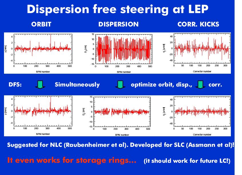
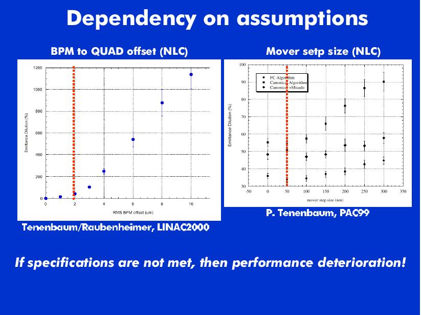
33 Main linacs-beam dynamics To achieve high luminosity, very small vertical emittances must be accelerated in very long linacs with small emittance growth and small beam jitter Normalized vertical emittance budget (500 GeV CM, units are mm) Location NLC/JLC TESLA CLIC Damping ring exit Linac entrance Linac exit IP Jitter budgets typically 0.1s (1000 nm to 60 nm in main linacs)
34 Main Linacs-beam dynamics Emittance growth is a quasi-static problemrequires component alignment at the micron level. Jitter is a dynamic problem, but control is needed at the tens of nanometer level. For both problems, beam diagnostics, tuning algorithms, and feedback are the keys to achieving the requirements.
35 Main linacs-beam dynamics: Sources of emittance growth Dispersive filamentation due to beam energy spread, together with Quadrupole position misalignments and rolls, and BPM errors, resulting in the generation of coupling and vertical dispersion. coherent oscillations at injection and/or component jitter Head-tail relative motion caused by transverse short-range wakefields, and relative motion of bunches in the train caused by transverse long-range wakefields, together with rf structure misalignments coherent oscillations at injection and/or component jitter (in what follows, blue background slides have been ripped off from Snowmass 01 talk by Ralph Assmann)
36
37
38
39 Main Linac-Beam dynamicsdispersive emittance growth Quadrupole and BPM position alignment at the micron level is required- the initial survey cannot be done with sufficient accuracy to satisfy this requirement. The beam itself (via the BPM s) must be used to find the centers of the quadrupoles. One of many possible methods: vary the strength of a quad, measure the orbit change, deduce the center of the quad. Quads are then moved onto the reference orbit using movable stands. Procedure is limited by systematic errors: e.g., motion of quad center with quad strength
40 Ballistic alignment: Divide beam line into bins with 12 quads each. Switch off all quads but one, steer to last BPM, align all other BPM s in bin to the beam. Switch on quads, align to BPMS s From CLIC design study:
41
42 Main linacs-beam dynamics - dispersive emittance growth Errors in this procedure (due to finite BPM resolution, beam jitter, etc). lead to some residual dispersion, which can be further reduced by DFS ( dispersion-free steering ). This procedure looks at linac trajectories at different energies and adjusts the quadrupole positions to achieve a gold orbit for which the dispersion is minimized.
43
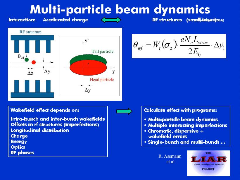
44 Main linacs: beam dynamicsshort range wakefields The beam breakup instability refers to a collective effect in which the head of the bunch, when moving off-axis through an rf structure, generates a force on the tail via short range transverse wakefields associated with the rf structures. If the head and the tail have the same natural oscillation frequency, the tail will be resonantly driven and can acquire a large amplitude. This causes the effective emittance of the bunch to grow.
45
46
47
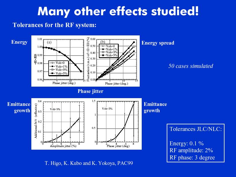
48 Main linacs: beam dynamics - short range wakefields The development of head-tail growth due to coherent oscillations at injection is controlled through the use of BNS damping : this is the establishment of a tune difference between the head and tail of the bunch, which suppresses the resonant driving of the tail. The tune difference is typically established by phasing the bunch off-crest in the rf wave, which results in a difference in energy between the head and the tail. The dependence of the tune on energy (chromaticity) then produces a tune difference between the head and the tail. The required energy spread, however, makes the dispersive effects noted above worse.
49
50
51 Main linacs: beam dynamics - short range wakefields Rf structure misalignments are minimized by the use of structure BPM s which measure directly the beam offset in the rf structure. The remaining residual effects may be partially cancelled by the introduction of non-dispersive bumps which produce wakefield effects which just cancel those of the structure misalignments. To tune the bumps: must measure the emittance- >laser devices. Beam size at b=50 m is about 1 micron->want to measure size to 10%, need resolution of 100 nm=>laser interferometer devices (resolution 60 nm seen at FFTB)
52 Non-dispersive bumps in TESLA
53 Main linacs-beam dynamicssingle bunch emittance growth Tolerance/instrumentation requirements: Machine Quad BPM resolution BNS energy spread Structure misalignment Structure BPM resolution TESLA 10 mm 0.35% 300 mm NLC/JLC 0.3 mm 0.8% 30 mm 5 mm CLIC 0.1 mm 2% 10 mm Emittance growth: Machine Static Quadrupole misalignments, after orbit correction with DFS Transverse wakes from structure misalignment, after ND bumps TESLA 2% 2% NLC/JLC 25% 7% CLIC Small 22%
54
55
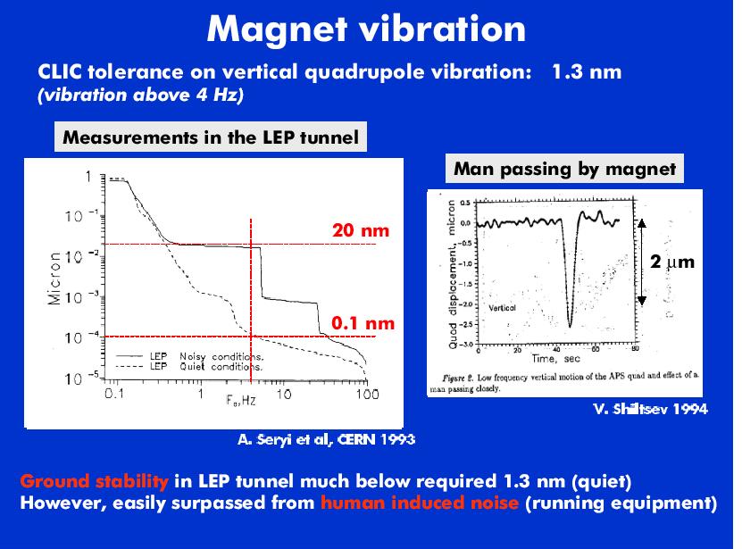
56 Main linacs: beam dynamicsground motion Ground motion- at frequencies above 1 Hz, typically it is at the 10 nm level or less. OK for most of main linacs-final doublet needs active stabilization. At lower frequencies (< 1Hz)-can be large, up to 100 nm-1 mm. However, such motion tends to be highly correlated (longwavelength)-tolerance is greater.
")
57 Frequency (Hz)
58 From Daniel Schulte (CERN)
59
60 Main linacs-beam dynamicsground motion It is possible to use beam-based feedback (using BPMs and linac correction dipoles) at low frequencies (~5 % of the cycle rate) to suppress jitter. Suppression of low frequency noise comes at the expense of high frequency noise amplification. Collision feedback at the IP within the bunch train will be very effective for high frequencies, but is difficult, except for TESLA, because of the small bunch separation.
61
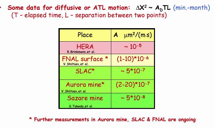
62 Main linacs-beam dynamicsground motion At very low frequencies (hour-day-month time scale), ground motion is diffusive: ATL law: Dx 2 =A*T*L: amplitudes can be large. May also have systematic long term motion such as settling. This large amplitude motion can cause misalignments to develop, leading to emittance dilution. It requires periodic realignment. The time between (invasive) realignments can be increased by the use of steering feedback.
63
64
65 CLIC emittance growth-500 GeV CM
66
67 Main linacs: beam dynamicsmultibunch emittance growth Multibunch emittance growth is driven by longrange wakefields Long-range wakefields in the warm structures (NLC/JLC, CLIC) are suppressed using damped, detuned cells: Cells are fabricated with a range of dipole frequencies=>destructive interference. In addition, dipole modes are also damped. Long range wakefields at TESLA are suppressed using HOM dampers at the ends of the cavities.
68
69 RDDS1 NLC structure long range wakefield
70

71 CLIC TDS structure
72
73 Long-range wakefield at TESLA
74
75 Main linacs: beam dynamics Issues Long range wakefield suppression in rf structures. Beam diagnostic device requirements for beambased alignment. Tuning algorithms for beam-based alignment. Simulations-are they accurate and inclusive? Feedback system development. Vibration and beam jitter suppression.
76 Main linacs: bunch compressors Parameter TESLA NLC CLIC First stage input energy (GeV) First stage input bunch length (mm) First stage length (m) First stage RF frequency (GHz) First stage RF voltage (MV) First stage output bunch length (mm) Second stage input energy (GeV) 8 9 Second stage length (m) Second stage RF frequency (GHz) Second stage RF voltage (MV) Second stage output bunch length (mm)
77 TESLA bunch compressor 3 TESLA rf modules are used to establish an energy-longitudinal position correlation in the bunch A 90 m wiggler section is used to establish an energy dependence to the path length, which, together with the energy-position correlation, compresses the bunch length (by a factor of 20). Energy spread reaches 3% in the wiggler
78
79 NLC/JLC bunch compressor A two stage system-first stage compression by a factor of 8, second stage a factor of 5. The stages are separated by a 6 GeV linac. The design decouples multibunch phase errors generated in the damping ring from energy variations at the final focus. Two-stage design limits energy spread to less than 2%.
80
81 CLIC bunch compressor A two stage system-first stage compresses by 12, second stage by 8. Stages are separated by a 7 GeV linac. Two stage system limits energy spread to less than 2%.
82
83 Bunch compressors-issues Emittance growth in the bunch compressors can result from Chromatic aberrations in the dispersive elements Coherent and incoherent synchrotron radiation. CSR will produce a correlation between longitudinal position and transverse position, similar to the effect of short-range wakefields.
Emittance preservation in TESLA
 Emittance preservation in TESLA R.Brinkmann Deutsches Elektronen-Synchrotron DESY,Hamburg, Germany V.Tsakanov Yerevan Physics Institute/CANDLE, Yerevan, Armenia The main approaches to the emittance preservation
ILC Beam Dynamics Studies Using PLACET
 ILC Beam Dynamics Studies Using PLACET Andrea Latina (CERN) July 11, 2007 John Adams Institute for Accelerator Science - Oxford (UK) Introduction Simulations Results Conclusions and Outlook PLACET Physical
X-Band RF Harmonic Compensation for Linear Bunch Compression in the LCLS
 SLAC-TN-5- LCLS-TN-1-1 November 1,1 X-Band RF Harmonic Compensation for Linear Bunch Compression in the LCLS Paul Emma SLAC November 1, 1 ABSTRACT An X-band th harmonic RF section is used to linearize
Studies of Emittance Bumps and Adaptive Alignment method for ILC Main Linac
 Studies of Emittance Bumps and Adaptive Alignment method for ILC Main Linac Nikolay Solyak #, Kirti Ranjan, Valentin Ivanov, Shekhar Mishra Fermilab 22-nd Particle Accelerator Conference, Albuquerque,
R.W. Aßmann, CERN SL-AP Snowmass 2001 July 7 th, 2001
 R.W. Aßmann, CERN SL-AP Snowmass 2001 July 7 th, 2001 (almost a Higgs) November 2 nd, 2000, 7am We can do this precision e+ephysics at the high-energy frontier! Push beyond 209 GeV at LEP (for the Higgs,
The TESLA Dogbone Damping Ring
 The TESLA Dogbone Damping Ring Winfried Decking for the TESLA Collaboration April 6 th 2004 Outline The Dogbone Issues: Kicker Design Dynamic Aperture Emittance Dilution due to Stray-Fields Collective
Status of linear collider designs:
 Status of linear collider designs: Electron and positron sources Design overview, principal open issues G. Dugan March 11, 2002 Electron sourcesfor 500 GeV CM machines Parameter TESLA NLC CLIC Cycle rate
Linear Collider Collaboration Tech Notes
 LCC 0035 07/01/00 Linear Collider Collaboration Tech Notes More Options for the NLC Bunch Compressors January 7, 2000 Paul Emma Stanford Linear Accelerator Center Stanford, CA Abstract: The present bunch
LCLS Accelerator Parameters and Tolerances for Low Charge Operations
 LCLS-TN-99-3 May 3, 1999 LCLS Accelerator Parameters and Tolerances for Low Charge Operations P. Emma SLAC 1 Introduction An option to control the X-ray FEL output power of the LCLS [1] by reducing the
e + e - Linear Collider
 e + e - Linear Collider Disclaimer This talk was lifted from an earlier version of a lecture by N.Walker Eckhard Elsen DESY DESY Summer Student Lecture 3 rd August 2006 1 Disclaimer II Talk is largely
Report from the Luminosity Working Group of the International Linear Collider Technical Review Committee (ILC-TRC) Chairman: Greg Loew
 Chairman: Greg Loew") Report from the Luminosity Working Group of the International Linear Collider Technical Review Committee (ILC-TRC) Chairman: Greg Loew The ILC-TRC was originally constituted in 1994 and produced a report
Report from the Luminosity Working Group of the International Linear Collider Technical Review Committee (ILC-TRC) Chairman: Greg Loew The ILC-TRC was originally constituted in 1994 and produced a report
6 Bunch Compressor and Transfer to Main Linac
 II-159 6 Bunch Compressor and Transfer to Main Linac 6.1 Introduction The equilibrium bunch length in the damping ring (DR) is 6 mm, too long by an order of magnitude for optimum collider performance (σ
Short Introduction to CLIC and CTF3, Technologies for Future Linear Colliders
 Short Introduction to CLIC and CTF3, Technologies for Future Linear Colliders Explanation of the Basic Principles and Goals Visit to the CTF3 Installation Roger Ruber Collider History p p hadron collider
WG2 on ERL light sources CHESS & LEPP
 Charge: WG2 on ERL light sources Address and try to answer a list of critical questions for ERL light sources. Session leaders can approach each question by means of (a) (Very) short presentations (b)
NLC Luminosity and Accelerator Physics
 Stanford Linear Accelerator Center X-Band Linear Collider Path to the Future NLC Luminosity and Accelerator Physics International Technology Recommendation Panel April 26-27, 2004 Outline Talk will focus
Two Beamline Ground Motion Simulation for NLC
 Two Beamline Ground Motion Simulation for NLC LCD group meeting May 28, 2002 Andrei Seryi for the NLC Accelerator Physics Group 1 of 25 Goal: Create a tool which will allow simulation of realistic behavior
Accelerator R&D Opportunities: Sources and Linac. Developing expertise. D. Rubin, Cornell University
 Accelerator R&D Opportunities: Sources and Linac D. Rubin, Cornell University Electron and positron sources Requirements Status of R&D Linac Modeling of beam dynamics Development of diagnostic and tuning
X-band RF driven hard X-ray FELs. Yipeng Sun ICFA Workshop on Future Light Sources March 5-9, 2012
 X-band RF driven hard X-ray FELs Yipeng Sun ICFA Workshop on Future Light Sources March 5-9, 2012 Motivations & Contents Motivations Develop more compact (hopefully cheaper) FEL drivers, L S C X-band (successful
Simulation for choice of RF phase and RF jitters in the main linac
 Simulation for choice of RF phase and RF jitters in the main linac 1998.12. Kiyoshi Kubo 1. Parameter of the linac Parameters for CMS energy 1TeV case B in the table Pre-ISG2 Parameters are used except
Fermilab HG cavity and coupler R&D
 Fermilab HG cavity and coupler R&D Motivation HOM calculations Nikolay Solyak Fermilab Outline Main Coupler and HOM dumping Multipactor Lorentz Forces Single bunch beam dynamics Summary Nikolay Solyak
THE CLIC PROJECT - STATUS AND PROSPECTS
 THE CLIC PROJECT - STATUS AND PROSPECTS E. Adli, University of Oslo, Norway On behalf of the CLIC/CTF3 collaboration Abstract Following the feasibility demonstration of the novel CLIC technology and the
Steering Simulation Studies
 Steering Simulation Studies Machine Advisory Committee Meeting 24 June 23 The Situation in November 2 Capability to realistically simulate both commissioning and operation of any proposed LC is critical
3. Synchrotrons. Synchrotron Basics
 1 3. Synchrotrons Synchrotron Basics What you will learn about 2 Overview of a Synchrotron Source Losing & Replenishing Electrons Storage Ring and Magnetic Lattice Synchrotron Radiation Flux, Brilliance
A 6 GeV Compact X-ray FEL (CXFEL) Driven by an X-Band Linac
 Driven by an X-Band Linac") A 6 GeV Compact X-ray FEL (CXFEL) Driven by an X-Band Linac Zhirong Huang, Faya Wang, Karl Bane and Chris Adolphsen SLAC Compact X-Ray (1.5 Å) FEL Parameter symbol LCLS CXFEL unit Bunch Charge Q 250 250
A 6 GeV Compact X-ray FEL (CXFEL) Driven by an X-Band Linac Zhirong Huang, Faya Wang, Karl Bane and Chris Adolphsen SLAC Compact X-Ray (1.5 Å) FEL Parameter symbol LCLS CXFEL unit Bunch Charge Q 250 250
CERN - European Laboratory for Particle Physics / ~2»~7. CLIC Study Annual Report summarised by I. Wilson for the CLIC Study Group
 65 CLl(,-l\}OT - $"L?l B wj l I CERN - European Laboratory for Particle Physics / ~2»~7 CLIC Note 327 17.02.97 OCR Output CLIC Study Annual Report 1996 summarised by I. Wilson for the CLIC Study Group
Optics considerations for
 Optics considerations for ERL x-ray x sources Georg H. Hoffstaetter* Physics Department Cornell University Ithaca / NY Georg.Hoffstaetter@cornell.edu 1. Overview of Parameters 2. Critical Topics 3. Phase
ILC Spin Rotator. Super B Workshop III. Presenter: Jeffrey Smith, Cornell University. with
 ILC Spin Rotator Super B Workshop III Presenter: Jeffrey Smith, Cornell University with Peter Schmid, DESY Peter Tenenbaum and Mark Woodley, SLAC Georg Hoffstaetter and David Sagan, Cornell Based on NLC
S2E (Start-to-End) Simulations for PAL-FEL. Eun-San Kim
 Simulations for PAL-FEL. Eun-San Kim") S2E (Start-to-End) Simulations for PAL-FEL Aug. 25 2008 Kyungpook Nat l Univ. Eun-San Kim 1 Contents I Lattice and layout for a 10 GeV linac II Beam parameters and distributions III Pulse-to-pulse stability
S2E (Start-to-End) Simulations for PAL-FEL Aug. 25 2008 Kyungpook Nat l Univ. Eun-San Kim 1 Contents I Lattice and layout for a 10 GeV linac II Beam parameters and distributions III Pulse-to-pulse stability
Accelerator Physics. Accelerator Development
 Accelerator Physics The Taiwan Light Source (TLS) is the first large accelerator project in Taiwan. The goal was to build a high performance accelerator which provides a powerful and versatile light source
Overview of Linear Collider Designs
 Overview of Linear Collider Designs SLAC-PUB-6244 April 1993 (4 R. H. Siemann Stanford Linear Accelerator Center, Stanford University, Stanford, CA 94309 I. INTRODUCTION Linear collider design and development
SPPS: The SLAC Linac Bunch Compressor and Its Relevance to LCLS
 LCLS Technical Advisory Committee December 10-11, 2001. SPPS: The SLAC Linac Bunch Compressor and Its Relevance to LCLS Patrick Krejcik LCLS Technical Advisory Committee Report 1: July 14-15, 1999 The
THE COMPACT LINEAR COLLIDER (CLIC) STUDY
 STUDY") THE COMPACT LINEAR COLLIDER (CLIC) STUDY J.P.Delahaye for The Compact LInear Collider Study Team The CLIC study is a site independent feasibility study aiming at the development of a realistic technology
THE COMPACT LINEAR COLLIDER (CLIC) STUDY J.P.Delahaye for The Compact LInear Collider Study Team The CLIC study is a site independent feasibility study aiming at the development of a realistic technology
Main Linac Beam Dynamics. Kiyoshi KUBO (Some slides will be skipped in the lecture, due to the limited time.)
") Main Linac Beam Dynamics Kiyoshi KUBO 26.5.22 (Some slides will be skipped in the lecture, due to the limited time.) ILC Main Linac Beam Dynamics Introduction Lattice design Beam quality preservation Longitudinal
Main Linac Beam Dynamics Kiyoshi KUBO 26.5.22 (Some slides will be skipped in the lecture, due to the limited time.) ILC Main Linac Beam Dynamics Introduction Lattice design Beam quality preservation Longitudinal
$)ODW%HDP(OHFWURQ6RXUFHIRU/LQHDU&ROOLGHUV
ODW%HDP(OHFWURQ6RXUFHIRU/LQHDU&ROOLGHUV") $)ODW%HDP(OHFWURQ6RXUFHIRU/LQHDU&ROOLGHUV R. Brinkmann, Ya. Derbenev and K. Flöttmann, DESY April 1999 $EVWUDFW We discuss the possibility of generating a low-emittance flat (ε y
$)ODW%HDP(OHFWURQ6RXUFHIRU/LQHDU&ROOLGHUV R. Brinkmann, Ya. Derbenev and K. Flöttmann, DESY April 1999 $EVWUDFW We discuss the possibility of generating a low-emittance flat (ε y
Diagnostics Needs for Energy Recovery Linacs
 Diagnostics Needs for Energy Recovery Linacs Georg H. Hoffstaetter Cornell Laboratory for Accelerator-based Sciences and Education & Physics Department Cornell University, Ithaca New York 14853-2501 gh77@cornell.edu
Accelerator Physics. Tip World Scientific NEW JERSEY LONDON SINGAPORE BEIJING SHANGHAI HONG KONG TAIPEI BANGALORE. Second Edition. S. Y.
 Accelerator Physics Second Edition S. Y. Lee Department of Physics, Indiana University Tip World Scientific NEW JERSEY LONDON SINGAPORE BEIJING SHANGHAI HONG KONG TAIPEI BANGALORE Contents Preface Preface
3.5 / E [%] σ E s [km]
![3.5 / E [%] σ E s [km]](/thumbs/83/88409757.jpg "3.5 / E [%] σ E s [km]") ZDR - Simulation Studies of the NLC Main Linacs R. Assmann, C. Adolphsen, K. Bane, K. Thompson, T. O. Raubenheimer Stanford Linear Accelerator Center, Stanford, California 9439 May 1996 Abstract This study
ZDR - Simulation Studies of the NLC Main Linacs R. Assmann, C. Adolphsen, K. Bane, K. Thompson, T. O. Raubenheimer Stanford Linear Accelerator Center, Stanford, California 9439 May 1996 Abstract This study
Impedance & Instabilities
 Impedance & Instabilities The concept of wakefields and impedance Wakefield effects and their relation to important beam parameters Beam-pipe geometry and materials and their impact on impedance An introduction
Physics 610. Adv Particle Physics. April 7, 2014
 Physics 610 Adv Particle Physics April 7, 2014 Accelerators History Two Principles Electrostatic Cockcroft-Walton Van de Graaff and tandem Van de Graaff Transformers Cyclotron Betatron Linear Induction
Linear Collider Collaboration Tech Notes
 LCC-0073 SLAC-PUB-9004 September 2001 Linear Collider Collaboration Tech Notes Microwave Quadrupoles for Beam Break-up Supression In the NLC Main Linac K.L.F. Bane and G. Stupakov Stanford Linear Accelerator
IP switch and big bend
 1 IP switch and big bend Contents 1.1 Introduction..................................................... 618 1.2 TheIPSwitch.................................................... 618 1.2.1 OpticsDesign...............................................
Transverse dynamics Selected topics. Erik Adli, University of Oslo, August 2016, v2.21
 Transverse dynamics Selected topics Erik Adli, University of Oslo, August 2016, Erik.Adli@fys.uio.no, v2.21 Dispersion So far, we have studied particles with reference momentum p = p 0. A dipole field
ThomX Machine Advisory Committee. (LAL Orsay, March ) Ring Beam Dynamics
 Ring Beam Dynamics") ThomX Machine Advisory Committee (LAL Orsay, March 20-21 2017) Ring Beam Dynamics A. Loulergue, M. Biagini, C. Bruni, I. Chaikovska I. Debrot, N. Delerue, A. Gamelin, H. Guler, J. Zang Programme Investissements
ThomX Machine Advisory Committee (LAL Orsay, March 20-21 2017) Ring Beam Dynamics A. Loulergue, M. Biagini, C. Bruni, I. Chaikovska I. Debrot, N. Delerue, A. Gamelin, H. Guler, J. Zang Programme Investissements
FACET-II Design Update
 FACET-II Design Update October 17-19, 2016, SLAC National Accelerator Laboratory Glen White FACET-II CD-2/3A Director s Review, August 9, 2016 Planning for FACET-II as a Community Resource FACET-II Photo
Superconducting Electron Linacs
 Superconducting Electron Linacs Nick Walker DESY CAS Zeuthen 15-16 Sept. 3 What s in Store Brief history of superconducting RF Choice of frequency (SCRF for pedestrians) RF Cavity Basics (efficiency issues)
Tuning Techniques And Operator Diagnostics for FACET at SLAC National Accelerator Laboratory. Chris Melton SLAC Accelerator Operations
 Tuning Techniques And Operator Diagnostics for FACET at SLAC National Accelerator Laboratory Chris Melton SLAC Accelerator Operations FACET Tuning And Diagnostics What is FACET? FACET Performance Challenges
Introduction to particle accelerators
 Introduction to particle accelerators Walter Scandale CERN - AT department Lecce, 17 June 2006 Introductory remarks Particle accelerators are black boxes producing either flux of particles impinging on
ANALYSIS OF HIGH ORDER MODES IN 1.3 GHZ CW SRF ELECTRON LINAC FOR A LIGHT SOURCE
 ANALYSIS OF HIGH ORDER MODES IN 1.3 GHZ CW SRF ELECTRON LINAC FOR A LIGHT SOURCE A. Sukhanov, A. Vostrikov, V. Yakovlev, Fermilab, Batavia, IL 60510, USA Abstract Design of a Light Source (LS) based on
Linac Driven Free Electron Lasers (III)
") Linac Driven Free Electron Lasers (III) Massimo.Ferrario@lnf.infn.it SASE FEL Electron Beam Requirements: High Brightness B n ( ) 1+ K 2 2 " MIN r #$ % &B! B n 2 n K 2 minimum radiation wavelength energy
Linac Driven Free Electron Lasers (III) Massimo.Ferrario@lnf.infn.it SASE FEL Electron Beam Requirements: High Brightness B n ( ) 1+ K 2 2 " MIN r #$ % &B! B n 2 n K 2 minimum radiation wavelength energy
ILC concepts / schematic
 INFN School on Electron Accelerators 12-14 September 2007, INFN Sezione di Pisa Lecture 1a ILC concepts / schematic Carlo Pagani University of Milano INFN Milano-LASA & GDE The Standard Model Fundamental
Beam-beam Effects in Linear Colliders
 Beam-beam Effects in Linear Colliders Daniel Schulte D. Schulte Beam-beam effects in Linear Colliders 1 Generic Linear Collider Single pass poses luminosity challenge Low emittances are produced in the
Transverse beam stability and Landau damping in hadron colliders
 Work supported by the Swiss State Secretariat for Educa6on, Research and Innova6on SERI Transverse beam stability and Landau damping in hadron colliders C. Tambasco J. Barranco, X. Buffat, T. Pieloni Acknowledgements:
CERN EUROPEAN ORGANIZATION FOR NUCLEAR RESEARCH BEAM-BASED ALIGNMENT IN CTF3 TEST BEAM LINE
 CERN EUROPEAN ORGANIZATION FOR NUCLEAR RESEARCH CLIC Note 956 BEAM-BASED ALIGNMENT IN CTF3 TEST BEAM LINE Sterbini, G (CERN) ; Dӧbert, S (CERN) ; Marín, E (CERN) ; Lillestol, RL (CERN) ; Schulte, D (CERN)
PROGRESS ON NEXT GENERATION LINEAR COLLIDERS* 1. INTRODUCTION
 SLAC-PUB-4848 January 1989 (A/E) PROGRESS ON NEXT GENERATION LINEAR COLLIDERS* RONALD D. RUTH Stanford Linear Accelerator Center Stanford University, Stanford, California 94309 1. INTRODUCTION The purpose
CLIC Project Status. Roger Ruber. Uppsala University. On behalf of the CLIC Collaborations. Thanks to all colleagues for materials
 CLIC Project Status Roger Ruber Uppsala University On behalf of the CLIC Collaborations Thanks to all colleagues for materials IAS 2018 Program on High Energy Physics Hong Kong, 23 January 2018 CLIC Collaborations
Beam Dynamics. Gennady Stupakov. DOE High Energy Physics Review June 2-4, 2004
 Beam Dynamics Gennady Stupakov DOE High Energy Physics Review June 2-4, 2004 Beam Dynamics Research in ARDA Broad expertise in many areas: lattice design, collective effects, electron cloud, beam-beam
PAL LINAC UPGRADE FOR A 1-3 Å XFEL
 PAL LINAC UPGRADE FOR A 1-3 Å XFEL J. S. Oh, W. Namkung, Pohang Accelerator Laboratory, POSTECH, Pohang 790-784, Korea Y. Kim, Deutsches Elektronen-Synchrotron DESY, D-603 Hamburg, Germany Abstract With
Lattice Design and Performance for PEP-X Light Source
 Lattice Design and Performance for PEP-X Light Source Yuri Nosochkov SLAC National Accelerator Laboratory With contributions by M-H. Wang, Y. Cai, X. Huang, K. Bane 48th ICFA Advanced Beam Dynamics Workshop
Review of proposals of ERL injector cryomodules. S. Belomestnykh
 Review of proposals of ERL injector cryomodules S. Belomestnykh ERL 2005 JLab, March 22, 2005 Introduction In this presentation we will review injector cryomodule designs either already existing or under
The International Linear Collider. Barry Barish Caltech 2006 SLUO Annual Meeting 11-Sept-06
 The International Linear Collider Barry Barish Caltech 2006 SLUO Annual Meeting 11-Sept-06 Why e + e - Collisions? elementary particles well-defined energy, angular momentum uses full COM energy produces
Introduction to accelerators for teachers (Korean program) Mariusz Sapiński CERN, Beams Department August 9 th, 2012
 Mariusz Sapiński CERN, Beams Department August 9 th, 2012") Introduction to accelerators for teachers (Korean program) Mariusz Sapiński (mariusz.sapinski@cern.ch) CERN, Beams Department August 9 th, 2012 Definition (Britannica) Particle accelerator: A device producing
Introduction to accelerators for teachers (Korean program) Mariusz Sapiński (mariusz.sapinski@cern.ch) CERN, Beams Department August 9 th, 2012 Definition (Britannica) Particle accelerator: A device producing
PARTICLE BEAMS, TOOLS FOR MODERN SCIENCE AND MEDICINE Hans-H. Braun, CERN
 5 th Particle Physics Workshop National Centre for Physics Quaid-i-Azam University Campus, Islamabad PARTICLE BEAMS, TOOLS OR MOERN SCIENCE AN MEICINE Hans-H. Braun, CERN 3 rd Lecture Introduction to Linear
Beam Physics at SLAC. Yunhai Cai Beam Physics Department Head. July 8, 2008 SLAC Annual Program Review Page 1
 Beam Physics at SLAC Yunhai Cai Beam Physics Department Head July 8, 2008 SLAC Annual Program Review Page 1 Members in the ABP Department * Head: Yunhai Cai * Staff: Gennady Stupakov Karl Bane Zhirong
VI/463 QUADRUPOLE ALIGNMENT AND TRAJECTORY CORREC- TION FOR FUTURE LINEAR COLLIDERS: SLC TESTS OF A DISPERSION-FREE STEERING ALGORITHM 1
 VI/463 QUADRUPOLE ALIGNMENT AND TRAJECTORY CORREC- TION FOR FUTURE LINEAR COLLIDERS: SLC TESTS OF A DISPERSION-FREE STEERING ALGORITHM 1 R. Assmann, T. Chen, F.J. Decker, M. Minty, T. Raubenheimer, R.
Superconducting RF Accelerators: Why all the interest?
 Superconducting RF Accelerators: Why all the interest? William A. Barletta Director, United States Particle Accelerator School Dept. of Physics, MIT The HEP prespective ILC PROJECT X Why do we need RF
Stanford Linear Accelerator Center
 LCLS Linac Overview Vinod Bharadwaj Stanford Linear Accelerator Center Vinod Bharadwaj Linac Overview 15 min Gennady Stupakov CSR Effects- Theory 20 min Paul Emma LCLS Linac Update 20 min Mike Borland
Short Pulse, Low charge Operation of the LCLS. Josef Frisch for the LCLS Commissioning Team
 Short Pulse, Low charge Operation of the LCLS Josef Frisch for the LCLS Commissioning Team 1 Normal LCLS Parameters First Lasing in April 10, 2009 Beam to AMO experiment August 18 2009. Expect first user
Linac optimisation for the New Light Source
 Linac optimisation for the New Light Source NLS source requirements Electron beam requirements for seeded cascade harmonic generation LINAC optimisation (2BC vs 3 BC) CSR issues energy chirp issues jitter
Recent Progress at the CLIC Test Facility 3 at CERN
 Recent Progress at the CLIC Test acility 3 at CERN P. Urschütz Talk outline Introduction to the CLIC two-beam scheme The CLIC Test acility CT3 Results from CT3 Past Recent Results Outlook on future activities
CERN EUROPEAN ORGANIZATION FOR NUCLEAR RESEARCH ADVANCES IN HIGH-GRADIENT ACCELERATING STRUCTURES AND IN THE UNDERSTANDING GRADIENT LIMITS
 CERN EUROPEAN ORGANIZATION FOR NUCLEAR RESEARCH CLIC Note 1111 ADVANCES IN HIGH-GRADIENT ACCELERATING STRUCTURES AND IN THE UNDERSTANDING GRADIENT LIMITS Walter Wuensch CERN, Geneva, Switzerland Abstract
COMBINER RING LATTICE
 CTFF3 TECHNICAL NOTE INFN - LNF, Accelerator Division Frascati, April 4, 21 Note: CTFF3-2 COMBINER RING LATTICE C. Biscari 1. Introduction The 3 rd CLIC test facility, CTF3, is foreseen to check the feasibility
Electron acceleration behind self-modulating proton beam in plasma with a density gradient. Alexey Petrenko
 Electron acceleration behind self-modulating proton beam in plasma with a density gradient Alexey Petrenko Outline AWAKE experiment Motivation Baseline parameters Longitudinal motion of electrons Effect
On the future plan of KEK for ILC(International Linear Collider) Junji Urakawa(KEK) Contents
 Junji Urakawa(KEK) Contents") On the future plan of KEK for ILC(International Linear Collider) Junji Urakawa(KEK) 2004.10.24 Contents 0. Outline until now. Review of SC-LC(TESLA) and R&D items. R&D Items at ATF. R&D plans for Superconducting
On the future plan of KEK for ILC(International Linear Collider) Junji Urakawa(KEK) 2004.10.24 Contents 0. Outline until now. Review of SC-LC(TESLA) and R&D items. R&D Items at ATF. R&D plans for Superconducting
A Two-Stage Bunch Compressor Option for the US Cold LC
 LCC-0151 SLAC-TN-0-048 June 2004 Linear Collider Collaboration Tech Notes A Two-Stage Bunch Compressor Option for the US Cold LC Abstract This note documents a set of expressions used to explore the issue
III. CesrTA Configuration and Optics for Ultra-Low Emittance David Rice Cornell Laboratory for Accelerator-Based Sciences and Education
 III. CesrTA Configuration and Optics for Ultra-Low Emittance David Rice Cornell Laboratory for Accelerator-Based Sciences and Education Introduction Outline CESR Overview CESR Layout Injector Wigglers
Future Light Sources March 5-9, 2012 Low- alpha mode at SOLEIL 1
 Introduction: bunch length measurements Reminder of optics Non- linear dynamics Low- alpha operation On the user side: THz and X- ray short bunch science CSR measurement and modeling Future Light Sources
TESLA LINEAR COLLIDER DESIGN AND R&D STATUS
 TESLA LINEAR COLLIDER DESIGN AND R&D STATUS R. Brinkmann (for the TESLA Collaboration) DESY, D-2263 Hamburg, Germany Abstract This paper summarises the present status of the overall design and of the technical
Tools of Particle Physics I Accelerators
 Tools of Particle Physics I Accelerators W.S. Graves July, 2011 MIT W.S. Graves July, 2011 1.Introduction to Accelerator Physics 2.Three Big Machines Large Hadron Collider (LHC) International Linear Collider
SBF Accelerator Principles
 SBF Accelerator Principles John Seeman SLAC Frascati Workshop November 11, 2005 Topics The Collision Point Design constraints going backwards Design constraints going forward Parameter relations Luminosity
LC Commissioning, Operations and Availability
 International Technology Recommendation Panel X-Band Linear Collider Path to the Future LC Commissioning, Operations and Availability Tom Himel Stanford Linear Accelerator Center April 26-27, 2004 Integrating
Excitements and Challenges for Future Light Sources Based on X-Ray FELs
 Excitements and Challenges for Future Light Sources Based on X-Ray FELs 26th ADVANCED ICFA BEAM DYNAMICS WORKSHOP ON NANOMETRE-SIZE COLLIDING BEAMS Kwang-Je Kim Argonne National Laboratory and The University
CLIC Detector studies status + plans
 CLIC Detector studies status + plans Contents: - Introduction to CLIC accelerator - 2004 CLIC Study group report: "Physics at the CLIC Multi-TeV Linear Collider - CERN participation in Linear Collider
Current and Future Developments in Accelerator Facilities. Jordan Nash, Imperial College London
 Current and Future Developments in Accelerator Facilities Jordan Nash, Imperial College London Livingston chart (circa 1985) Nearly six decades of continued growth in the energy reach of accelerators Driven
High performance computing simulations. for multi-particle effects in the synchrotons
 High performance computing simulations for multi-particle effects in the synchrotons Content What is the HSC section doing? Physics basics PyHEADTAIL software Simulations of the PS Simulations of instabilities
Introduction to Accelerator Physics - Luminosity and Beam-Beam Effects. Lecture #5. February 27,1998. Dr. Bob Siemann
 Introduction to Accelerator Physics - Luminosity and Beam-Beam Effects Lecture #5 February 27,1998 Dr. Bob Siemann B -.,..-, :_.,.-................... I.r_......-....---- -... '.".. (.i :....._.,.,...
Experimental Measurements of the ORION Photoinjector Drive Laser Oscillator Subsystem
 Experimental Measurements of the ORION Photoinjector Drive Laser Oscillator Subsystem D.T Palmer and R. Akre Laser Issues for Electron RF Photoinjectors October 23-25, 2002 Stanford Linear Accelerator
Linear Collider Studies at DESY
 Linear Collider Studies at DESY R. Brinkmann for the TESLA and SBLC Collaborations DESY, Notkestr. 85, D-22603 Hamburg, Germany ABSTRACT This paper summarizes the present status of the studies for a superconducting
Overview of HEMC Scheme
 Overview of HEMC Scheme R. B. Palmer, (BNL) JLab 2/28/2011 My birthday Progress on Cooling simulations New Acceleration sequence with higher transmission New System transmission estimate New Wall power
Beam. RF antenna. RF cable
 Status of LEP2 J. Wenninger, SL Operation for the SL division LEPC September 1998 Outline Optics and RF for 1998 Beam current limitations Injection and ramp Performance at high energy Conclusions LEPC/15-09-98
FACET-II Design, Parameters and Capabilities
 FACET-II Design, Parameters and Capabilities 217 FACET-II Science Workshop, October 17-2, 217 Glen White Overview Machine design overview Electron systems Injector, Linac & Bunch compressors, Sector 2
Operational Experience with HERA
 PAC 07, Albuquerque, NM, June 27, 2007 Operational Experience with HERA Joachim Keil / DESY On behalf of the HERA team Contents Introduction HERA II Luminosity Production Experiences with HERA Persistent
FURTHER UNDERSTANDING THE LCLS INJECTOR EMITTANCE*
 Proceedings of FEL014, Basel, Switzerland FURTHER UNDERSTANDING THE LCLS INJECTOR EMITTANCE* F. Zhou, K. Bane, Y. Ding, Z. Huang, and H. Loos, SLAC, Menlo Park, CA 9405, USA Abstract Coherent optical transition
ASTRA simulations of the slice longitudinal momentum spread along the beamline for PITZ
 ASTRA simulations of the slice longitudinal momentum spread along the beamline for PITZ Orlova Ksenia Lomonosov Moscow State University GSP-, Leninskie Gory, Moscow, 11999, Russian Federation Email: ks13orl@list.ru
CSR calculation by paraxial approximation
 CSR calculation by paraxial approximation Tomonori Agoh (KEK) Seminar at Stanford Linear Accelerator Center, March 3, 2006 Short Bunch Introduction Colliders for high luminosity ERL for short duration
BERLinPro. An ERL Demonstration facility at the HELMHOLTZ ZENTRUM BERLIN
 BERLinPro An ERL Demonstration facility at the HELMHOLTZ ZENTRUM BERLIN BERLinPro: ERL demonstration facility to prepare the ground for a few GeV ERL @ Berlin-Adlershof Goal: 100MeV, 100mA beam Small emittance,
Critical R&D Issues for ILC Damping Rings and New Test Facilities
 Critical R&D Issues for ILC Damping Rings and New Test Facilities Andy Wolski Cockcroft Institute/University of Liverpool PAC 2007, Albuquerque, New Mexico. 1 ILC Key Parameters Given the main linac parameters:
Wakefield Suppression for CLIC A Manifold Damped and Detuned Structure
 Wakefield Suppression for CLIC A Manifold Damped and Detuned Structure Roger M. Jones Cockcroft Institute and The University of Manchester 1 Wake 2. Function FP420 RF Suppression Staff for CLIC -Staff
Accelerators. Lecture V. Oliver Brüning. school/lecture5
 Accelerators Lecture V Oliver Brüning AB/ABP http://bruening.home.cern.ch/bruening/summer school/lecture5 V) LEP, LHC + more LEP LHC Other HEP Projects Future Projects What else? LEP Precision Experiment:
CHALLENGES IN FUTURE LINEAR COLLIDERS
 CHALLENGES IN FUTURE LINEAR COLLIDERS Swapan Chattopadhyay and Kaoru Yokoya Abstract For decades, electron-positron colliders have been complementing proton-proton colliders. But the circular LEP, the
LCLS-II SCRF start-to-end simulations and global optimization as of September Abstract
 SLAC National Accelerator Lab LCLS-II TN-17-4 February 217 LCLS-II SCRF start-to-end simulations and global optimization as of September 216 G. Marcus SLAC, Menlo Park, CA 9425 J. Qiang LBNL, Berkeley,