R.W. Aßmann, CERN SL-AP Snowmass 2001 July 7 th, 2001
|
|
|
- Marion Payne
- 6 years ago
- Views:
Transcription
1 R.W. Aßmann, CERN SL-AP Snowmass 2001 July 7 th, 2001
")

2 (almost a Higgs) November 2 nd, 2000, 7am
3 We can do this precision e+ephysics at the high-energy frontier! Push beyond 209 GeV at LEP (for the Higgs, ) Problem: This talk: Compare and recommend Sorry, folks: This is up to you
4 1. Introduction The LC design studies Simulation codes Beam dynamics beam energy 2. Single particle dynamics Optics design Example lattices Dispersion and energy spread 3. Multi-particle dynamics Transverse wakefield BNS damping SLC as the reference Emittance/wakefield optimization Predicted LC performance Required component performance 4. Transverse beam stability Predictions for LC designs LEP experience Stability studies (vibration damping) 5. Multi-bunch effects Knowledge of long-range wakefield Multi-bunch emittance growth Effects production errors/damage 6. Conclusion
5 This talk: It is not: Discuss some design choices Explain some trade-offs Illustrate some beam dynamics topics Use of simple example lattices, estimates Include some detailed, published LC studies A detailed review of all issues (would be a book) Common simulations for the three designs Any judgment on the different approaches Greg Loews International LC Study Group Talk based on my direct experience with SLC, CLIC, and NLC. But, more importantly: The work of many, many colleagues! Acknowledgements to all of them, especially: TESLA: R. Brinkmann and colleagues CLIC: D. Schulte, G. Guignard and colleagues NLC: T. Raubenheimer, P. Tenenbaum, A. Seryi and colleagues SLC: The old gang
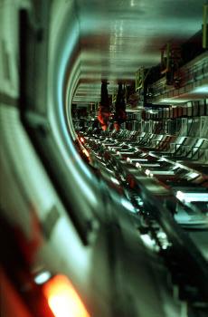
6 The main linacs: The heart of linear colliders. Their crucial mission for the success of linear colliders: Provide beam energy of interest for physics Issues: High efficiency High accelerating gradients Reliable RF system Minimize cost per MV Transport high current and small emittance beams for high luminosity Issues: Transverse emittance dilution Energy sharpness, stability Transverse position stability Tails and beam losses Beam dynamics
7 TESLA SLC NLC/JLC CLIC (stage II) C.M. energy GeV Luminosity cm -2 s Frequency GHz Iris radius mm Gradient MV/m Bunch popul # bunches f rep Hz ge x (inj) mm-mrad ge y (inj) mm-mrad Basic scaling: Luminosity ~ Energy 2
8 Linac performance (static) characterized with: Beam current Transverse emittances Energy spread γε γε + γε + final inj disp γε wf Tolerance: γε disp + γε wf γε Wakefields ~ f 3 Beam parameters Tolerances on: Straightness of trajectory Centering in RF structures inj Required luminosity mm-mrad (SLC) mm-mrad (NLC/JLC) mm-mrad (TESLA) mm-mrad (CLIC) High gradient (high frequency) allows high beam energies, for the price of more stringent tolerances on alignment Tolerances scale with 1/f J.P. Delahaye et al For an optimized design
9 Test accelerators cannot test linac performance. Predict linac performance based on simulation codes Programs used in the context of linear collider studies: LIAR MAFIA TRANSPORT SAD MAD GUINEAPIG MERLIN TraFIC 4 MUSTAFA PLACET Q URMEL DIMAD GDFIDL LEGO WAKE TRACK FFADA PARMELA FLUKA GEANT CAIN OMEGA3P TAU3P HFSS PHI3P + many others (some nameless heroes) Computational activity for linear colliders is: manifold and redundant Especially: LIAR written for and tested against SLC linac Incorporates lot of experience from SLC Used for cross-checks of other programs (e.g. PLACET)
10 Beam energy is a crucial parameter for linear collider design. Target energy or energy range set by particle physics! Choice of technology determines the energy range: TESLA: JLC/NLC: CLIC: up to 800 GeV up to 1000 GeV up to 3000 GeV Linear collider design is not energy-independent Comparison of designs for different energies can be misleading! Compare designs for the same beam energy (G. Loew et al).
11 1. Introduction The LC design studies Simulation codes Beam dynamics beam energy 2. Single particle dynamics Optics design Example lattices Dispersion and energy spread 3. Multi-particle dynamics Transverse wakefield BNS damping SLC as the reference Emittance/wakefield optimization Predicted LC performance Required component performance 4. Transverse beam stability Predictions for LC designs LEP experience Stability studies (vibration damping) 5. Multi-bunch effects Knowledge of long-range wakefield Multi-bunch emittance growth Effects production errors/damage 6. Conclusion
12 1) Provide focusing for beam transport (no real challenge, FODO) 2) Minimize effects from kicks (wakefield) on the beam Offset y at s 2 due to kick at s 1 y( s2) = R12( s1, s2) θ ( s1) R = 12 β 1 β 2 E E 1 2 sin ( ψ ) Keep design beam size at s 2 constant (b 2 =const) For a given kick: y( s β 2 ) 1 Stronger focusing helps if kick amplitude does not depend on linac optics (wakefield kicks, injection errors) Weaker focusing helps for dispersive quadrupole kicks. (fewer quadrupole kicks)

 CLIC (3 TeV) NLC (1 TeV)")
13 TDR Dispersion-dominated optics design Wakefield-dominated optics design TESLA (.5 TeV) CLIC (3 TeV) NLC (1 TeV) Yellow report ZDR
14 y cell l b l b (250 GeV example) 72º m ~ 40 m CLIC 80º m ~ 80 m JLC/NLC 60º m ~ 360 m TESLA Note: CLIC below 45 m for 250 GeV TESLA more sensitive to ground motion waves with Long wavelength Low frequency Larger amplitude
15 Not fully realistic 90 degree FODO lattice Cell length β y (max/min) 10.0 m 17 / 2.9 m 20.0 m 34 / 5.9 m 40.0 m 68 / 11.8 m 80.0 m 136 / 23.5 m CLIC NLC TESLA Injection energy: 10 GeV Acceleration length: 96 % of cell length Assume: 250 GeV Linac length: 1890 m (135.0 MV/m) ~189 cells a 10 m 4290 m ( 59.0 MV/m) ~215 cells a 20 m m ( 23.4 MV/m) ~135 cells a 80 m
16 Trajectory in the CLIC, TESLA, JLC/NLC control rooms Assume: 100 mm QD offset at start of linac, low current (no WF s) CLIC type JLC/NLC type TESLA type (all 250 GeV)
17 Example case CLIC type no acceleration no wakefields QD misaligned by 50 mm Filamentation Emittance saturates due to filamentation for large energy spread (chromatic phase mixing)
18 Correlated, fractional energy spread (CLIC/NLC: BNS) Linac Linac exit RF curvature contribution TESLA: < 0.06 % 0.06% % NLC: < 0.80 % 0.25 % % CLIC: < 0.55 % 0.35 % % QD offset by 0.3 mm -> Y oscillation with amplitude ~ 1mm Example: σ E /E ε disp ε inj CLIC type 0.4% mm-mrad mm-mrad NLC type 0.6% mm-mrad mm-mrad TESLA type 0.05% mm-mrad mm-mrad Dispersion no problem, if trajectory controlled on 1 mm level! (pessimistic assumptions: No wakefields would mean no BNS)
19 1. Introduction The LC design studies Simulation codes Beam dynamics beam energy 2. Single particle dynamics Optics design Example lattices Dispersion and energy spread 3. Multi-particle dynamics Transverse wakefield BNS damping SLC as the reference Emittance/wakefield optimization Predicted LC performance Required component performance 4. Transverse beam stability Predictions for LC designs LEP experience Stability studies (vibration damping) 5. Multi-bunch effects Knowledge of long-range wakefield Multi-bunch emittance growth Effects production errors/damage 6. Conclusion
 Longitudinal distribution Charge Energy Optics RF phases Calculate effect with programs: Multi-particle beam dynamics Multiple interacting imperfections Chromatic,")
20 Interaction: Accelerated charge RF structures (small irises) (except TESLA) θ wf = W σ t en L 2E e struc ( z ) y1 0 Wakefield effect depends on: Intra-bunch and inter-bunch wakefields Offsets in rf structures (imperfections) Longitudinal distribution Charge Energy Optics RF phases Calculate effect with programs: Multi-particle beam dynamics Multiple interacting imperfections Chromatic, dispersive + wakefield errors Single-bunch and multi-bunch R. Assmann et al
 with smaller iris radius!")
21 Choice of technology determines radius of structure iris a: High frequency small a Low frequency large a Stronger wakefields (beam induced electro-magnetic fields) with smaller iris radius! Beam is closer to metallic walls
22
23 Bunch length: Transverse wakefield (at 1 σ z ): TESLA SLC NLC CLIC 300 mm 1100 mm 110 mm 30 mm TESLA 22 V/pC/m 2 SLC 1990 V/pC/m 2 NLC V/pC/m 2 CLIC V/pC/m 2 Injection energy: TESLA 5.0 GeV SLC 1.2 GeV NLC 8.0 GeV CLIC 9.0 GeV + Bunch intensity: TESLA SLC NLC CLIC BEAM
24 Represent bunch by two slices: separated by σ z each half charge θ wf = W σ t en L ( ) e struc z y1 2E 0 For 100 µm structure offset and 1 m structure length: TESLA: 0.7 nrad NLC: 86.1 nrad CLIC: nrad SLC: nrad Not done: Normalize to emittance Input structure length Wakefield kick for CLIC at 1.5 TeV almost down to TESLA at 5 GeV (1/3 larger)
25 Introduce correlated energy spread (RF phase) so that head and tail move together (same phase advance). No beam-breakup. NLC CLIC M. Woodley et al, PAC01 CLIC yellow report No BNS damping required for TESLA RF phase CLIC: ~ 6 degree
 multiplicative")
26 Single bunch emittance growth (SLC 1996/1997): R. Assmann, PAC97 γε 28 = κ γε initial + γε wf Problems due to poor emittance stability (drift towards larger emittances) multiplicative additive Simulation: κ = 1.06 γε wf = 2 Reasonable agreement with data from the SLC!
 Methods: - 1-to-1")
 - Dispersion-free steering - Emittance")
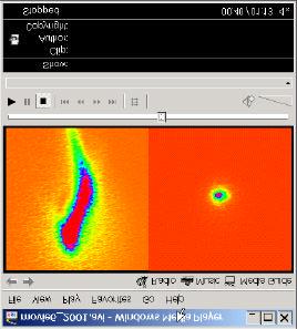
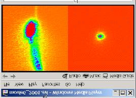
27 Learnt how to go from Left case (start of tuning) to Right case (end of tuning) Methods: - 1-to-1 steering (steer flat) - RF phasing (energy profile) - Dispersion-free steering - Emittance bump tuning
28
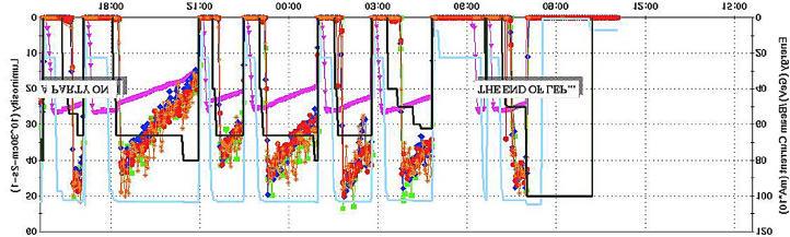
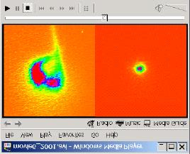
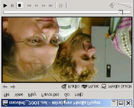
29 Low repetition rates (5-120 Hz) Small beam sizes (shown was smaller area than LEP) No equilibrium state, no damping after damping rings Every pulse is different The beam is living Asymmetric beam distributions, tails due to wakefields Intense tuning needed to control beam sizes and stability (much better for super-conducting linacs) Wakefield effects can be corrected very efficiently (took a while for SLC to learn how)
30 Vertical emittance growth in the linac (normalized): ε y SLC 2 mm-mrad TESLA 0.01 mm-mrad JLC/NLC mm-mrad CLIC mm-mrad Measured Lower wakefields (SC rf) Parameter optimization (charge, bunch length, ) Minimize wakefields and dispersion! Stringent requirements (JLC/NLC, CLIC) on: - alignment (beam-based) - steering (magnet, rf structure movements) - feedbacks - beam instrumentation Innovative methods have been developed
31 TESLA NLC CLIC 1-to-1 1-to-1 1-to-1 Shunt method Shunt method Ballistic correction Dispersion-free steering Moving procedure (local) Multi-step lining-up Dispersion-free steering Emittance bumps Emittance bumps Shunt method ( k-modulation ) (FFTB, HERA, LEP, ) Dispersion-free steering (SLC, LEP, ) Ballistic alignment Multi-step lining-up Emittance bumps (SLC) Vary quad K, measure change in trajectory, fit BPM to quad misalignment Minimize orbit, dispersion information together Minimum orbit/dispersion -> Straight trajectory Hidden bump in orbit shows up as dispersion oscillation. Switch off quadrupoles. Beam defines straight axis. Measure BPM offsets to axis. Similar to dispersion-free steering. (Modify quad strengths) Introduce wakefield kicks that compensate wakefield kicks from imperfections.

!")
32 ORBIT DISPERSION CORR. KICKS DFS: Simultaneously optimize orbit, disp., corr. Suggested for NLC (Raubenheimer et al). Developed for SLC (Assmann et al)! It even works for storage rings (it should work for future LC!)
33 CLIC (D Amico,Guignard, Schulte) TESLA (CDR) Ballistic correction Multi-step + bumps Dispersion-free steering
34 Requirements and predicted LC performance TESLA JLC/NLC CLIC Quadrupole offset *# 300 mm 50.0 mm 50.0 mm Quadrupole roll mrad ~100 mrad BPM resolution 10 mm 0.3 mm 0.1 mm BPM-quad offset 100 mm 2.0 mm n/a BPM offset (axis) n/a n/a 10.0 mm Structure offset # 500 mm 30.0 mm 10.0 mm RF BPM offset/resol n/a 5.0 mm 5.0 mm Mover resolution n/a 50.0 nm 0.5 mm Emittance growth (a) One-to-one 1000 % ~ 1000 % 2700 % (b) All methods 3 % 40 % 15 % * Initial offset, before beam-based alignment # Achievable performance depends on instrumentation, environment, accessibility, (e.g. worse inside of cryostats)
35 BPM to QUAD offset (NLC) Mover setp size (NLC) Tenenbaum/Raubenheimer, LINAC2000 P. Tenenbaum, PAC99 If specifications are not met, then performance deterioration!


36 Tolerances for the RF system: Energy Energy spread 50 cases simulated Phase jitter Emittance growth Emittance growth Tolerances JLC/NLC: T. Higo, K. Kubo and K. Yokoya, PAC99 Energy: 0.1 % RF amplitude: 2% RF phase: 3 degree
37 1. Introduction The LC design studies Simulation codes Beam dynamics beam energy 2. Single particle dynamics Optics design Example lattices Dispersion and energy spread 3. Multi-particle dynamics Transverse wakefield BNS damping SLC as the reference Emittance/wakefield optimization Predicted LC performance Required component performance 4. Transverse beam stability Predictions for LC designs LEP experience Stability studies (vibration damping) 5. Multi-bunch effects Knowledge of long-range wakefield Multi-bunch emittance growth Effects production errors/damage 6. Conclusion
38 1) Beam position stability: Quadrupole vibration/drift drives coherent betatron oscillations. Feedback inefficient below ~ 0.04 * f rep Tolerance set by σ exit = (βε exit ) 1/2 2) Emittance stability: Betatron oscillation drives transverse emittance growth. TESLA JLC/NLC CLIC Quadrupole jitter nm 10 nm 1.3 nm Offset jitter [σ y ] A [10-7 µm 2 /s/m] Orbit drift 1 σ y in 30s - - Emittance growth - 29% in 30 min 11% in 1min Correction w/o fdbk 15 min Correction w fdbk 10 h 3 days Note: 1) Take drifts as rough estimates! Different hardware, feedback constellation, tuning methods! No consistent operational procedure simulated 2) Different A reflects different geological conditions (sandy rock; site-specific)
39 Luminosity decay due to vertical orbit drifts: L cm s per minute ε nm per minute Orbit correction ε ε 1.5% / min De/e ~ 1.5 % / min for best performance Luminosity stabilized with the vertical orbit feedback ( autopilot ) every 7-8 minutes (3% effect). Orbit stabilization: ~ 20 mm level. Both visible from experiments and beam lifetime BCT (faster)! No reason to be afraid of fast orbit stabilization
40 CLIC tolerance on vertical quadrupole vibration: 1.3 nm (vibration above 4 Hz) Measurements in the LEP tunnel Man passing by magnet 20 nm 2 µm 0.1 nm V. Shiltsev 1994 A. Seryi et al, CERN 1993 Ground stability in LEP tunnel much below required 1.3 nm (quiet) However, easily surpassed from human induced noise (running equipment)
41 CLIC Magnet Stability Study M. Aleksa, R. Assmann, W. Coosemans, G. Guignard, N. Leros, M. Mayoud, S. Redaelli, F. Ruggiero, S. Russenschuck, D. Schulte, A. Verdier, I. Wilson, F. Zimmermann - CERN: SL, PS, EST, LHC divisions involved - CERN test stand on main site (surface, close to road, accelerators, equipment). - Collaboration with SLAC/NLC. Contacts with DESY and FNAL. Since January 2001 fully approved Goal: The goal of the proposed study is to show that the present design parameters of CLIC are feasible in a real accelerator environment, using and further developing latest cutting-edge stabilization technology and time-dependent simulation programs. Active and passive stabilization technology subject of intense industrial research and development. Applications: Chip lithography, electron-transmission microscopy, NMR devices, solid-sate physics, satellites, airplanes, gravitational wave detectors, lasers, E.g. If TEM can achieve 0.05 nm resolution why can t we use this? SLAC:Strong effort for final doublet stabilization (Seryi, Frisch, ) Number of recent papers by A. Seryi (see also T working group)

42 26th Advanced ICFA Beam Dynamics Workshop on Nanometre-Size Colliding Particle Beams CERN, September 2002 Amongst other topics, address many stability issues! Where is the limit? Hope for input from colleagues in our field and from other fields. Can we give a limit? Please contact R. Assmann or F. Zimmermann if you have ideas, input, special requests!
43 1. Introduction The LC design studies Simulation codes Beam dynamics beam energy 2. Single particle dynamics Optics design Example lattices Dispersion and energy spread 3. Multi-particle dynamics Transverse wakefield BNS damping SLC as the reference Emittance/wakefield optimization Predicted LC performance Required component performance 4. Transverse beam stability Predictions for LC designs LEP experience Stability studies (vibration damping) 5. Multi-bunch effects Knowledge of long-range wakefield Multi-bunch emittance growth Effects production errors/damage 6. Conclusion
44 Input: Calculations + ASSET tests. Optimize design... CLIC structure: (scaled to 15 GHz) Measured (black) and calculated (red) transverse wakefield versus time [ns] Wakefield (V/pC/mm) I. Wilson et al EPAC2000 Time [ns] Very good agreement, except unexpected 7.6 GHz component HFSS: vacuum chamber to beam pipe transition, not the structure itself Time [ns]
45 TAU3P calculation for 10 cells compared with measurements: (RDDS accelerator structure, NLC) Dipole Mode Spectrum Dipole Mode Frequency (GHz) Amplitude Measurement Tau3P (350) (400) Frequency [Hz] Very good accuracy! Cho Ng, Brian Mc Candless, ICAP2000
46 HOM damping requirements for the TESLA superstructures Worst result (10 cases) Cavity misalignment 500 mm 21.7 MV/m gradient 27 modes: Q = 2e5 4 modes: Q = 1e5 N. Baboi et al EPAC2000 Measured HOM OK for TESLA Multi-bunch offsets at the end of the TESLA linac Calculated multi-bunch emittance growth along the TESLA linac e y = 20 E-09 m rad
 ideal")

![Function [V/pC/mm/m]](/docs-images/73/68587466/images/47-2.jpg "s [m] s [m] (b) 2")


47 Envelope of wakefield: (a) ideal R. Jones et al, EPAC2000 Wake Function [V/pC/mm/m] s [m] s [m] (b) 2 MHz rms error (c) 5 MHz rms error Emittance growth: BPM position [km] 4% 600% s [m] BPM position [km]
48 1. Introduction The LC design studies Simulation codes Beam dynamics beam energy 2. Single particle dynamics Optics design Example lattices Dispersion and energy spread 3. Multi-particle dynamics Transverse wakefield BNS damping SLC as the reference Emittance/wakefield optimization Predicted LC performance Required component performance 4. Transverse beam stability Predictions for LC designs LEP experience Stability studies (vibration damping) 5. Multi-bunch effects Knowledge of long-range wakefield Multi-bunch emittance growth Effects production errors/damage 6. Conclusion
49 Linac beam dynamics is a very rich field. It depends strongly on choice of RF technology and beam energy. Predictions are based on detailed simulations. Simulation codes are connected closely to SLC experience. Good reproduction of SLC data. Solutions are published for LC proposals up to 3 TeV. Relevant beam dynamics is understood. No reasonable doubts on simulation results. But: What is reasonable input? Work ongoing to establish most realistic input data (test accelerators, magnet stability study, ) (fully base design on measured performance of components)
Status of linear collider designs:
 Status of linear collider designs: Main linacs Design overview, principal open issues G. Dugan March 11, 2002 Linear colliders: main linacs The main linac is the heart of the linear collider TESLA, NLC/JLC,
Emittance preservation in TESLA
 Emittance preservation in TESLA R.Brinkmann Deutsches Elektronen-Synchrotron DESY,Hamburg, Germany V.Tsakanov Yerevan Physics Institute/CANDLE, Yerevan, Armenia The main approaches to the emittance preservation
The TESLA Dogbone Damping Ring
 The TESLA Dogbone Damping Ring Winfried Decking for the TESLA Collaboration April 6 th 2004 Outline The Dogbone Issues: Kicker Design Dynamic Aperture Emittance Dilution due to Stray-Fields Collective
Report from the Luminosity Working Group of the International Linear Collider Technical Review Committee (ILC-TRC) Chairman: Greg Loew
 Chairman: Greg Loew") Report from the Luminosity Working Group of the International Linear Collider Technical Review Committee (ILC-TRC) Chairman: Greg Loew The ILC-TRC was originally constituted in 1994 and produced a report
Report from the Luminosity Working Group of the International Linear Collider Technical Review Committee (ILC-TRC) Chairman: Greg Loew The ILC-TRC was originally constituted in 1994 and produced a report
ILC Beam Dynamics Studies Using PLACET
 ILC Beam Dynamics Studies Using PLACET Andrea Latina (CERN) July 11, 2007 John Adams Institute for Accelerator Science - Oxford (UK) Introduction Simulations Results Conclusions and Outlook PLACET Physical
Studies of Emittance Bumps and Adaptive Alignment method for ILC Main Linac
 Studies of Emittance Bumps and Adaptive Alignment method for ILC Main Linac Nikolay Solyak #, Kirti Ranjan, Valentin Ivanov, Shekhar Mishra Fermilab 22-nd Particle Accelerator Conference, Albuquerque,
Two Beamline Ground Motion Simulation for NLC
 Two Beamline Ground Motion Simulation for NLC LCD group meeting May 28, 2002 Andrei Seryi for the NLC Accelerator Physics Group 1 of 25 Goal: Create a tool which will allow simulation of realistic behavior
Lattice Design and Performance for PEP-X Light Source
 Lattice Design and Performance for PEP-X Light Source Yuri Nosochkov SLAC National Accelerator Laboratory With contributions by M-H. Wang, Y. Cai, X. Huang, K. Bane 48th ICFA Advanced Beam Dynamics Workshop
VI/463 QUADRUPOLE ALIGNMENT AND TRAJECTORY CORREC- TION FOR FUTURE LINEAR COLLIDERS: SLC TESTS OF A DISPERSION-FREE STEERING ALGORITHM 1
 VI/463 QUADRUPOLE ALIGNMENT AND TRAJECTORY CORREC- TION FOR FUTURE LINEAR COLLIDERS: SLC TESTS OF A DISPERSION-FREE STEERING ALGORITHM 1 R. Assmann, T. Chen, F.J. Decker, M. Minty, T. Raubenheimer, R.
3.5 / E [%] σ E s [km]
![3.5 / E [%] σ E s [km]](/thumbs/83/88409757.jpg "3.5 / E [%] σ E s [km]") ZDR - Simulation Studies of the NLC Main Linacs R. Assmann, C. Adolphsen, K. Bane, K. Thompson, T. O. Raubenheimer Stanford Linear Accelerator Center, Stanford, California 9439 May 1996 Abstract This study
ZDR - Simulation Studies of the NLC Main Linacs R. Assmann, C. Adolphsen, K. Bane, K. Thompson, T. O. Raubenheimer Stanford Linear Accelerator Center, Stanford, California 9439 May 1996 Abstract This study
Monochromatization Option for NLC Collisions
 LCC-0134 SLAC-TN-04-003 February 19, 2004 Linear Collider Collaboration Tech Notes Monochromatization Option for NLC Collisions Andrei Seryi, Tor Raubenheimer Stanford Linear Accelerator Center Stanford
$)ODW%HDP(OHFWURQ6RXUFHIRU/LQHDU&ROOLGHUV
ODW%HDP(OHFWURQ6RXUFHIRU/LQHDU&ROOLGHUV") $)ODW%HDP(OHFWURQ6RXUFHIRU/LQHDU&ROOLGHUV R. Brinkmann, Ya. Derbenev and K. Flöttmann, DESY April 1999 $EVWUDFW We discuss the possibility of generating a low-emittance flat (ε y
$)ODW%HDP(OHFWURQ6RXUFHIRU/LQHDU&ROOLGHUV R. Brinkmann, Ya. Derbenev and K. Flöttmann, DESY April 1999 $EVWUDFW We discuss the possibility of generating a low-emittance flat (ε y
Steering Simulation Studies
 Steering Simulation Studies Machine Advisory Committee Meeting 24 June 23 The Situation in November 2 Capability to realistically simulate both commissioning and operation of any proposed LC is critical
Accelerator R&D Opportunities: Sources and Linac. Developing expertise. D. Rubin, Cornell University
 Accelerator R&D Opportunities: Sources and Linac D. Rubin, Cornell University Electron and positron sources Requirements Status of R&D Linac Modeling of beam dynamics Development of diagnostic and tuning
Linear Collider Collaboration Tech Notes
 LCC-0073 SLAC-PUB-9004 September 2001 Linear Collider Collaboration Tech Notes Microwave Quadrupoles for Beam Break-up Supression In the NLC Main Linac K.L.F. Bane and G. Stupakov Stanford Linear Accelerator
Linear Collider Collaboration Tech Notes
 LCC 0035 07/01/00 Linear Collider Collaboration Tech Notes More Options for the NLC Bunch Compressors January 7, 2000 Paul Emma Stanford Linear Accelerator Center Stanford, CA Abstract: The present bunch
ILC Spin Rotator. Super B Workshop III. Presenter: Jeffrey Smith, Cornell University. with
 ILC Spin Rotator Super B Workshop III Presenter: Jeffrey Smith, Cornell University with Peter Schmid, DESY Peter Tenenbaum and Mark Woodley, SLAC Georg Hoffstaetter and David Sagan, Cornell Based on NLC
6 Bunch Compressor and Transfer to Main Linac
 II-159 6 Bunch Compressor and Transfer to Main Linac 6.1 Introduction The equilibrium bunch length in the damping ring (DR) is 6 mm, too long by an order of magnitude for optimum collider performance (σ
Impedance & Instabilities
 Impedance & Instabilities The concept of wakefields and impedance Wakefield effects and their relation to important beam parameters Beam-pipe geometry and materials and their impact on impedance An introduction
Abstract. results that address this question for the main linacs of the NLC. We will show that the effects of alignment drifts can indeed be handled.
 SLAC-PUB-732 September 1996 Emittance Dilution Due to Slow Alignment Drifts in the Main Linacs of the NLC* R. Assmann, C. Adolphsen, K. Bane, T.O. Raubenheimer, K. Thompson Stanford Linear Accelerator
Beam-beam Effects in Linear Colliders
 Beam-beam Effects in Linear Colliders Daniel Schulte D. Schulte Beam-beam effects in Linear Colliders 1 Generic Linear Collider Single pass poses luminosity challenge Low emittances are produced in the
X-band RF driven hard X-ray FELs. Yipeng Sun ICFA Workshop on Future Light Sources March 5-9, 2012
 X-band RF driven hard X-ray FELs Yipeng Sun ICFA Workshop on Future Light Sources March 5-9, 2012 Motivations & Contents Motivations Develop more compact (hopefully cheaper) FEL drivers, L S C X-band (successful
On-axis injection into small dynamic aperture
 On-axis injection into small dynamic aperture L. Emery Accelerator Systems Division Argonne National Laboratory Future Light Source Workshop 2010 Tuesday March 2nd, 2010 On-Axis (Swap-Out) injection for
Beam Dynamics. D. Brandt, CERN. CAS Bruges June 2009 Beam Dynamics D. Brandt 1
 Beam Dynamics D. Brandt, CERN D. Brandt 1 Some generalities D. Brandt 2 Units: the electronvolt (ev) The electronvolt (ev)) is the energy gained by an electron travelling, in vacuum, between two points
CEPC Linac Injector. HEP Jan, Cai Meng, Guoxi Pei, Jingru Zhang, Xiaoping Li, Dou Wang, Shilun Pei, Jie Gao, Yunlong Chi
 HKUST Jockey Club Institute for Advanced Study CEPC Linac Injector HEP218 22 Jan, 218 Cai Meng, Guoxi Pei, Jingru Zhang, Xiaoping Li, Dou Wang, Shilun Pei, Jie Gao, Yunlong Chi Institute of High Energy
First propositions of a lattice for the future upgrade of SOLEIL. A. Nadji On behalf of the Accelerators and Engineering Division
 First propositions of a lattice for the future upgrade of SOLEIL A. Nadji On behalf of the Accelerators and Engineering Division 1 SOLEIL : A 3 rd generation synchrotron light source 29 beamlines operational
Integrated luminosity performance studies of linear colliders with intra-train IP-FB system: ILC and CLIC
 Integrated luminosity performance studies of linear colliders with intra-train IP-FB system: ILC and CLIC Javier Resta Lopez JAI, Oxford University In collaboration with P. N. Burrows, A. Latina and D.
e + e - Linear Collider
 e + e - Linear Collider Disclaimer This talk was lifted from an earlier version of a lecture by N.Walker Eckhard Elsen DESY DESY Summer Student Lecture 3 rd August 2006 1 Disclaimer II Talk is largely
Short Introduction to CLIC and CTF3, Technologies for Future Linear Colliders
 Short Introduction to CLIC and CTF3, Technologies for Future Linear Colliders Explanation of the Basic Principles and Goals Visit to the CTF3 Installation Roger Ruber Collider History p p hadron collider
LAYOUT AND SIMULATIONS OF THE FONT SYSTEM AT ATF2
 LAYOUT AND SIMULATIONS OF THE FONT SYSTEM AT ATF J. Resta-López, P. N. Burrows, JAI, Oxford University, UK August 1, Abstract We describe the adaptation of a Feedback On Nano-second Timescales (FONT) system
Bernhard Holzer, CERN-LHC
 Bernhard Holzer, CERN-LHC * Bernhard Holzer, CERN CAS Prague 2014 x Liouville: in reasonable storage rings area in phase space is constant. A = π*ε=const x ε beam emittance = woozilycity of the particle
Transverse dynamics Selected topics. Erik Adli, University of Oslo, August 2016, v2.21
 Transverse dynamics Selected topics Erik Adli, University of Oslo, August 2016, Erik.Adli@fys.uio.no, v2.21 Dispersion So far, we have studied particles with reference momentum p = p 0. A dipole field
COMPUTATIONAL NEEDS FOR THE ILC
 Proceedings of ICAP 2006, Chamonix, France MOMPMP02 COMPUTATIONAL NEEDS FOR THE ILC D. Schulte, CERN, K. Kubo, KEK Abstract The ILC requires detailed studies of the beam transport and of individual components
FACET-II Design Update
 FACET-II Design Update October 17-19, 2016, SLAC National Accelerator Laboratory Glen White FACET-II CD-2/3A Director s Review, August 9, 2016 Planning for FACET-II as a Community Resource FACET-II Photo
A Two-Stage Bunch Compressor Option for the US Cold LC
 LCC-0151 SLAC-TN-0-048 June 2004 Linear Collider Collaboration Tech Notes A Two-Stage Bunch Compressor Option for the US Cold LC Abstract This note documents a set of expressions used to explore the issue
NLC Luminosity and Accelerator Physics
 Stanford Linear Accelerator Center X-Band Linear Collider Path to the Future NLC Luminosity and Accelerator Physics International Technology Recommendation Panel April 26-27, 2004 Outline Talk will focus
Accelerator Physics. Accelerator Development
 Accelerator Physics The Taiwan Light Source (TLS) is the first large accelerator project in Taiwan. The goal was to build a high performance accelerator which provides a powerful and versatile light source
Physics 610. Adv Particle Physics. April 7, 2014
 Physics 610 Adv Particle Physics April 7, 2014 Accelerators History Two Principles Electrostatic Cockcroft-Walton Van de Graaff and tandem Van de Graaff Transformers Cyclotron Betatron Linear Induction
CERN EUROPEAN ORGANIZATION FOR NUCLEAR RESEARCH BEAM-BASED ALIGNMENT IN CTF3 TEST BEAM LINE
 CERN EUROPEAN ORGANIZATION FOR NUCLEAR RESEARCH CLIC Note 956 BEAM-BASED ALIGNMENT IN CTF3 TEST BEAM LINE Sterbini, G (CERN) ; Dӧbert, S (CERN) ; Marín, E (CERN) ; Lillestol, RL (CERN) ; Schulte, D (CERN)
ThomX Machine Advisory Committee. (LAL Orsay, March ) Ring Beam Dynamics
 Ring Beam Dynamics") ThomX Machine Advisory Committee (LAL Orsay, March 20-21 2017) Ring Beam Dynamics A. Loulergue, M. Biagini, C. Bruni, I. Chaikovska I. Debrot, N. Delerue, A. Gamelin, H. Guler, J. Zang Programme Investissements
ThomX Machine Advisory Committee (LAL Orsay, March 20-21 2017) Ring Beam Dynamics A. Loulergue, M. Biagini, C. Bruni, I. Chaikovska I. Debrot, N. Delerue, A. Gamelin, H. Guler, J. Zang Programme Investissements
Accelerator Physics Issues of ERL Prototype
 Accelerator Physics Issues of ERL Prototype Ivan Bazarov, Geoffrey Krafft Cornell University TJNAF ERL site visit (Mar 7-8, ) Part I (Bazarov). Optics. Space Charge Emittance Compensation in the Injector
CLIC Detector studies status + plans
 CLIC Detector studies status + plans Contents: - Introduction to CLIC accelerator - 2004 CLIC Study group report: "Physics at the CLIC Multi-TeV Linear Collider - CERN participation in Linear Collider
II) Experimental Design
 Experimental Design") SLAC Experimental Advisory Committee --- September 12 th, 1997 II) Experimental Design Theory and simulations Great promise of significant scientific and technological achievements! How to realize this
SLAC Experimental Advisory Committee --- September 12 th, 1997 II) Experimental Design Theory and simulations Great promise of significant scientific and technological achievements! How to realize this
Overview of Acceleration
 Overview of Acceleration R B Palmer, Scott Berg, Steve Kahn (presented by Steve Kahn) Nufact-04 RF Frequency Acc types and System Studies Linacs RLA s FFAG s Injection/Extraction US Study 2a acceleration
D. Brandt, CERN. CAS Frascati 2008 Accelerators for Newcomers D. Brandt 1
 Accelerators for Newcomers D. Brandt, CERN D. Brandt 1 Why this Introduction? During this school, you will learn about beam dynamics in a rigorous way but some of you are completely new to the field of
SLS at the Paul Scherrer Institute (PSI), Villigen, Switzerland
, Villigen, Switzerland") SLS at the Paul Scherrer Institute (PSI), Villigen, Switzerland Michael Böge 1 SLS Team at PSI Michael Böge 2 Layout of the SLS Linac, Transferlines Booster Storage Ring (SR) Beamlines and Insertion Devices
SLS at the Paul Scherrer Institute (PSI), Villigen, Switzerland Michael Böge 1 SLS Team at PSI Michael Böge 2 Layout of the SLS Linac, Transferlines Booster Storage Ring (SR) Beamlines and Insertion Devices
Linear Collider Collaboration Tech Notes. A New Structure for the NLC Positron Predamping Ring Lattice
 Linear Collider Collaboration Tech Notes LCC-0066 CBP Tech Note - 233 June 2001 A New Structure for the NLC Positron Predamping Ring Lattice A. Wolski Lawrence Berkeley National Laboratory Berkeley, CA
X-Band RF Harmonic Compensation for Linear Bunch Compression in the LCLS
 SLAC-TN-5- LCLS-TN-1-1 November 1,1 X-Band RF Harmonic Compensation for Linear Bunch Compression in the LCLS Paul Emma SLAC November 1, 1 ABSTRACT An X-band th harmonic RF section is used to linearize
MAX-lab. MAX IV Lattice Design: Multibend Achromats for Ultralow Emittance. Simon C. Leemann
 Workshop on Low Emittance Rings 2010 CERN Jan 12 15, 2010 MAX-lab MAX IV Lattice Design: Multibend Achromats for Ultralow Emittance Simon C. Leemann simon.leemann@maxlab.lu.se Brief Overview of the MAX
Excitements and Challenges for Future Light Sources Based on X-Ray FELs
 Excitements and Challenges for Future Light Sources Based on X-Ray FELs 26th ADVANCED ICFA BEAM DYNAMICS WORKSHOP ON NANOMETRE-SIZE COLLIDING BEAMS Kwang-Je Kim Argonne National Laboratory and The University
Simulation for choice of RF phase and RF jitters in the main linac
 Simulation for choice of RF phase and RF jitters in the main linac 1998.12. Kiyoshi Kubo 1. Parameter of the linac Parameters for CMS energy 1TeV case B in the table Pre-ISG2 Parameters are used except
Transverse beam stability and Landau damping in hadron colliders
 Work supported by the Swiss State Secretariat for Educa6on, Research and Innova6on SERI Transverse beam stability and Landau damping in hadron colliders C. Tambasco J. Barranco, X. Buffat, T. Pieloni Acknowledgements:
Proton-driven plasma wakefield acceleration
 Proton-driven plasma wakefield acceleration Matthew Wing (UCL) Motivation : particle physics; large accelerators General concept : proton-driven plasma wakefield acceleration Towards a first test experiment
Lattice Design for the Taiwan Photon Source (TPS) at NSRRC
 at NSRRC") Lattice Design for the Taiwan Photon Source (TPS) at NSRRC Chin-Cheng Kuo On behalf of the TPS Lattice Design Team Ambient Ground Motion and Civil Engineering for Low Emittance Electron Storage Ring Workshop
Lattice Design for the Taiwan Photon Source (TPS) at NSRRC Chin-Cheng Kuo On behalf of the TPS Lattice Design Team Ambient Ground Motion and Civil Engineering for Low Emittance Electron Storage Ring Workshop
Overview on Compton Polarimetry
 General Issues O spin motion & alignment tolerances O beam-beam effects & upstream vs. Downstream Compton Polarimetry Basics O beam parameters & Compton detection methods O kinematics, cross sections &
CERN EUROPEAN ORGANIZATION FOR NUCLEAR RESEARCH THE CLIC POSITRON CAPTURE AND ACCELERATION IN THE INJECTOR LINAC
 CERN EUROPEAN ORGANIZATION FOR NUCLEAR RESEARCH CLIC Note - 819 THE CLIC POSITRON CAPTURE AND ACCELERATION IN THE INJECTOR LINAC A. Vivoli 1, I. Chaikovska 2, R. Chehab 3, O. Dadoun 2, P. Lepercq 2, F.
COMBINER RING LATTICE
 CTFF3 TECHNICAL NOTE INFN - LNF, Accelerator Division Frascati, April 4, 21 Note: CTFF3-2 COMBINER RING LATTICE C. Biscari 1. Introduction The 3 rd CLIC test facility, CTF3, is foreseen to check the feasibility
LCLS Injector Straight Ahead Spectrometer C.Limborg-Deprey Stanford Linear Accelerator Center 8 th June 2005
 LCLS Injector Straight Ahead Spectrometer C.Limborg-Deprey Stanford Linear Accelerator Center 8 th June 2005 Summary The spectrometer design was modified to allow the measurement of uncorrelated energy
A 6 GeV Compact X-ray FEL (CXFEL) Driven by an X-Band Linac
 Driven by an X-Band Linac") A 6 GeV Compact X-ray FEL (CXFEL) Driven by an X-Band Linac Zhirong Huang, Faya Wang, Karl Bane and Chris Adolphsen SLAC Compact X-Ray (1.5 Å) FEL Parameter symbol LCLS CXFEL unit Bunch Charge Q 250 250
A 6 GeV Compact X-ray FEL (CXFEL) Driven by an X-Band Linac Zhirong Huang, Faya Wang, Karl Bane and Chris Adolphsen SLAC Compact X-Ray (1.5 Å) FEL Parameter symbol LCLS CXFEL unit Bunch Charge Q 250 250
Introduction to Accelerators
 Introduction to Accelerators D. Brandt, CERN CAS Platja d Aro 2006 Introduction to Accelerators D. Brandt 1 Why an Introduction? The time where each accelerator sector was working alone in its corner is
Excitements and Challenges for Future Light Sources Based on X-Ray FELs
 Excitements and Challenges for Future Light Sources Based on X-Ray FELs 26th ADVANCED ICFA BEAM DYNAMICS WORKSHOP ON NANOMETRE-SIZE COLLIDING BEAMS Kwang-Je Kim Argonne National Laboratory and The University
III. CesrTA Configuration and Optics for Ultra-Low Emittance David Rice Cornell Laboratory for Accelerator-Based Sciences and Education
 III. CesrTA Configuration and Optics for Ultra-Low Emittance David Rice Cornell Laboratory for Accelerator-Based Sciences and Education Introduction Outline CESR Overview CESR Layout Injector Wigglers
LCLS Accelerator Parameters and Tolerances for Low Charge Operations
 LCLS-TN-99-3 May 3, 1999 LCLS Accelerator Parameters and Tolerances for Low Charge Operations P. Emma SLAC 1 Introduction An option to control the X-ray FEL output power of the LCLS [1] by reducing the
LHC Upgrade Plan and Ideas - scenarios & constraints from the machine side
 LHC Upgrade Plan and Ideas - scenarios & constraints from the machine side Frank Zimmermann LHCb Upgrade Workshop Edinburgh, 11 January 2007 Frank Zimmermann, LHCb Upgrade Workshop time scale of LHC upgrade
Overview of Linear Collider Designs
 Overview of Linear Collider Designs SLAC-PUB-6244 April 1993 (4 R. H. Siemann Stanford Linear Accelerator Center, Stanford University, Stanford, CA 94309 I. INTRODUCTION Linear collider design and development
Beam Physics at SLAC. Yunhai Cai Beam Physics Department Head. July 8, 2008 SLAC Annual Program Review Page 1
 Beam Physics at SLAC Yunhai Cai Beam Physics Department Head July 8, 2008 SLAC Annual Program Review Page 1 Members in the ABP Department * Head: Yunhai Cai * Staff: Gennady Stupakov Karl Bane Zhirong
Aperture Measurements and Implications
 Aperture Measurements and Implications H. Burkhardt, SL Division, CERN, Geneva, Switzerland Abstract Within short time, the 2/90 optics allowed to reach similar luminosity performance as the 90/60 optics,
3. Synchrotrons. Synchrotron Basics
 1 3. Synchrotrons Synchrotron Basics What you will learn about 2 Overview of a Synchrotron Source Losing & Replenishing Electrons Storage Ring and Magnetic Lattice Synchrotron Radiation Flux, Brilliance
Practical Lattice Design
 Practical Lattice Design Dario Pellegrini (CERN) dario.pellegrini@cern.ch USPAS January, 15-19, 2018 1/17 D. Pellegrini - Practical Lattice Design Lecture 5. Low Beta Insertions 2/17 D. Pellegrini - Practical
Operational Experience with HERA
 PAC 07, Albuquerque, NM, June 27, 2007 Operational Experience with HERA Joachim Keil / DESY On behalf of the HERA team Contents Introduction HERA II Luminosity Production Experiences with HERA Persistent
arxiv: v1 [physics.acc-ph] 21 Oct 2014
![arxiv: v1 [physics.acc-ph] 21 Oct 2014](/thumbs/89/99419860.jpg "arxiv: v1 [physics.acc-ph] 21 Oct 2014") SIX-DIMENSIONAL WEAK STRONG SIMULATIONS OF HEAD-ON BEAM BEAM COMPENSATION IN RHIC arxiv:.8v [physics.acc-ph] Oct Abstract Y. Luo, W. Fischer, N.P. Abreu, X. Gu, A. Pikin, G. Robert-Demolaize BNL, Upton,
SIX-DIMENSIONAL WEAK STRONG SIMULATIONS OF HEAD-ON BEAM BEAM COMPENSATION IN RHIC arxiv:.8v [physics.acc-ph] Oct Abstract Y. Luo, W. Fischer, N.P. Abreu, X. Gu, A. Pikin, G. Robert-Demolaize BNL, Upton,
IP switch and big bend
 1 IP switch and big bend Contents 1.1 Introduction..................................................... 618 1.2 TheIPSwitch.................................................... 618 1.2.1 OpticsDesign...............................................
PAL LINAC UPGRADE FOR A 1-3 Å XFEL
 PAL LINAC UPGRADE FOR A 1-3 Å XFEL J. S. Oh, W. Namkung, Pohang Accelerator Laboratory, POSTECH, Pohang 790-784, Korea Y. Kim, Deutsches Elektronen-Synchrotron DESY, D-603 Hamburg, Germany Abstract With
Accelerator Physics Final Exam pts.
 Accelerator Physics Final Exam - 170 pts. S. M. Lund and Y. Hao Graders: C. Richard and C. Y. Wong June 14, 2018 Problem 1 P052 Emittance Evolution 40 pts. a) 5 pts: Consider a coasting beam composed of
Fermilab HG cavity and coupler R&D
 Fermilab HG cavity and coupler R&D Motivation HOM calculations Nikolay Solyak Fermilab Outline Main Coupler and HOM dumping Multipactor Lorentz Forces Single bunch beam dynamics Summary Nikolay Solyak
Presented at the 5th International Linear Collider Workshop (LCWS 2000), Oct 24-28, 2000, Batavia, IL
, Oct 24-28, 2000, Batavia, IL") SLAC-PUB-10800 New NLC Final Focus Pantaleo Raimondi and Andrei Seryi Stanford Linear Accelerator Center, Stanford University, Stanford, California 94309 USA Abstract. A novel design of the Final Focus
SLAC-PUB-10800 New NLC Final Focus Pantaleo Raimondi and Andrei Seryi Stanford Linear Accelerator Center, Stanford University, Stanford, California 94309 USA Abstract. A novel design of the Final Focus
CERN EUROPEAN ORGANIZATION FOR NUCLEAR RESEARCH INTEGRATED SIMULATION OF DYNAMIC EFFECTS FOR THE 380 GEV CLIC DESIGN
 CERN EUROPEAN ORGANIZATION FOR NUCLEAR RESEARCH CLIC Note 1138 INTEGRATED SIMULATION OF DYNAMIC EFFECTS FOR THE 380 GEV CLIC DESIGN Chetan Gohil 1, Daniel Schulte 2, Philip N. Burrows 1 1 JAI, University
EUROPEAN ORGANIZATION FOR NUCLEAR RESEARCH CERN - SL DIVISION. Multi-TeV CLIC Photon Collider Option. H. Burkhardt
 EUROPEAN ORGANIZATION FOR NUCLEAR RESEARCH CERN - SL DIVISION CERN-SL-2000-070 CLIC Note 463 AP Multi-TeV CLIC Photon Collider Option H. Burkhardt Considerations for an option of γγ collisions at multi-tev
FACET-II Design, Parameters and Capabilities
 FACET-II Design, Parameters and Capabilities 217 FACET-II Science Workshop, October 17-2, 217 Glen White Overview Machine design overview Electron systems Injector, Linac & Bunch compressors, Sector 2
Diagnostics Needs for Energy Recovery Linacs
 Diagnostics Needs for Energy Recovery Linacs Georg H. Hoffstaetter Cornell Laboratory for Accelerator-based Sciences and Education & Physics Department Cornell University, Ithaca New York 14853-2501 gh77@cornell.edu
Physics 736. Experimental Methods in Nuclear-, Particle-, and Astrophysics. - Accelerator Techniques: Introduction and History -
 Physics 736 Experimental Methods in Nuclear-, Particle-, and Astrophysics - Accelerator Techniques: Introduction and History - Karsten Heeger heeger@wisc.edu Homework #8 Karsten Heeger, Univ. of Wisconsin
Simulation of Laser-Compton cooling of electron beams for future linear colliders. Abstract
 Simulation of Laser-Compton cooling of electron beams for future linear colliders T. Ohgaki Lawrence Berkeley National Laboratory Berkeley, California 94720, USA and Venture Business Laboratory, Hiroshima
SBF Accelerator Principles
 SBF Accelerator Principles John Seeman SLAC Frascati Workshop November 11, 2005 Topics The Collision Point Design constraints going backwards Design constraints going forward Parameter relations Luminosity
Introduction to Collider Physics
 Introduction to Collider Physics William Barletta United States Particle Accelerator School Dept. of Physics, MIT The Very Big Picture Accelerators Figure of Merit 1: Accelerator energy ==> energy frontier
On the future plan of KEK for ILC(International Linear Collider) Junji Urakawa(KEK) Contents
 Junji Urakawa(KEK) Contents") On the future plan of KEK for ILC(International Linear Collider) Junji Urakawa(KEK) 2004.10.24 Contents 0. Outline until now. Review of SC-LC(TESLA) and R&D items. R&D Items at ATF. R&D plans for Superconducting
On the future plan of KEK for ILC(International Linear Collider) Junji Urakawa(KEK) 2004.10.24 Contents 0. Outline until now. Review of SC-LC(TESLA) and R&D items. R&D Items at ATF. R&D plans for Superconducting
Start-to-end beam optics development and multi-particle tracking for the ILC undulator-based positron source*
 SLAC-PUB-12239 January 27 (A) Start-to-end beam optics development and multi-particle tracking for the ILC undulator-based positron source* F. Zhou, Y. Batygin, Y. Nosochkov, J. C. Sheppard, and M. D.
Part V Undulators for Free Electron Lasers
 Part V Undulators for Free Electron Lasers Pascal ELLEAUME European Synchrotron Radiation Facility, Grenoble V, 1/22, P. Elleaume, CAS, Brunnen July 2-9, 2003. Oscillator-type Free Electron Laser V, 2/22,
Introduction to particle accelerators
 Introduction to particle accelerators Walter Scandale CERN - AT department Lecce, 17 June 2006 Introductory remarks Particle accelerators are black boxes producing either flux of particles impinging on
LHC Luminosity and Energy Upgrade
 LHC Luminosity and Energy Upgrade Walter Scandale CERN Accelerator Technology department EPAC 06 27 June 2006 We acknowledge the support of the European Community-Research Infrastructure Activity under
TeV Scale Muon RLA Complex Large Emittance MC Scenario
 TeV Scale Muon RLA Complex Large Emittance MC Scenario Alex Bogacz and Kevin Beard Muon Collider Design Workshop, BNL, December 1-3, 29 Outline Large Emittance MC Neuffer s Collider Acceleration Scheme
Analysis of KEK-ATF Optics and Coupling Using Orbit Response Matrix Analysis 1
 Analysis of KEK-ATF Optics and Coupling Using Orbit Response Matrix Analysis 1 A. Wolski Lawrence Berkeley National Laboratory J. Nelson, M. Ross, M. Woodley Stanford Linear Accelerator Center S. Mishra
The Electron-Ion Collider
 The Electron-Ion Collider C. Tschalaer 1. Introduction In the past year, the idea of a polarized electron-proton (e-p) or electron-ion (e-a) collider of high luminosity (10 33 cm -2 s -1 or more) and c.m.
Linear Collider Studies at DESY
 Linear Collider Studies at DESY R. Brinkmann for the TESLA and SBLC Collaborations DESY, Notkestr. 85, D-22603 Hamburg, Germany ABSTRACT This paper summarizes the present status of the studies for a superconducting
Polarized electron and positron beams at CEPC
 Polarized electron and positron beams at CEPC Zhe Duan Institute of High Energy Physics, CAS Presented at mini-workshop on Beam polarization in future colliders IAS-HKUST, HK, Jan 18, 2019 zhe.duan@ihep.ac.cn
S2E (Start-to-End) Simulations for PAL-FEL. Eun-San Kim
 Simulations for PAL-FEL. Eun-San Kim") S2E (Start-to-End) Simulations for PAL-FEL Aug. 25 2008 Kyungpook Nat l Univ. Eun-San Kim 1 Contents I Lattice and layout for a 10 GeV linac II Beam parameters and distributions III Pulse-to-pulse stability
S2E (Start-to-End) Simulations for PAL-FEL Aug. 25 2008 Kyungpook Nat l Univ. Eun-San Kim 1 Contents I Lattice and layout for a 10 GeV linac II Beam parameters and distributions III Pulse-to-pulse stability
LCLS S-band Structure Coupler
 LCLS S-band Structure Coupler Zenghai Li Advanced Computations Department Stanford Linear Accelerator Center LCLS S-band L01/L02 Coupler Review Nov. 03, 2004 Overview Motivation Modeling tools Multipole
Compressor Ring. Contents Where do we go? Beam physics limitations Possible Compressor ring choices Conclusions. Valeri Lebedev.
 Compressor Ring Valeri Lebedev Fermilab Contents Where do we go? Beam physics limitations Possible Compressor ring choices Conclusions Muon Collider Workshop Newport News, VA Dec. 8-1, 8 Where do we go?
Status of the LHC Beam Cleaning Study Group
 Status of the LHC Beam Cleaning Study Group R. Assmann, SL BI Review 19.11.2001 BI Review 19.11.01, R. Assmann 1 LHC Beam Cleaning Study Group: Mandate: Study beam dynamics and operational issues for the
Compressor Lattice Design for SPL Beam
 EUROPEAN ORGANIZATION FOR NUCLEAR RESEARCH CERN A&B DIVISION AB-Note-27-34 BI CERN-NUFACT-Note-153 Compressor Lattice Design for SPL Beam M. Aiba Abstract A compressor ring providing very short proton
EFFECTS OF RF DEFLECTIONS ON BEAM DYNAMICS IN LINEAR COLLIDERS*
 SLAC-PUB-5069 September 1989 09 EFFECTS OF RF DEFLECTIONS ON BEAM DYNAMICS IN LINEAR COLLIDERS* J. T. SEEMAN Stanford Linear Accelerator Center, Stanford University, Stanford, CA 94309. Abstract The beam