Catapult tests for microgravity characterization of the MICROSCOPE accelerometers. Manuel Rodrigues On behalf ONERA & ZARM team
|
|
|
- Edwin Merritt
- 5 years ago
- Views:
Transcription


1 Catapult tests for microgravity characterization of the MICROSCOPE accelerometers Manuel Rodrigues On behalf ONERA & ZARM team 1
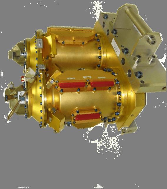
 Each mass = inertial sensor (defines measurement frame) 360 x 348 x 180 mm 3-25kg MQV1 MV2 Front End")


2 Instrument Description SU sqm Sensor Unit (SU) = differential accelerometer 2 SU on a Mechanics Interface (SUMI) Each SU = 2 concentric Test-Masses (Pt-Rh/Pt-Rh or Ti/Pt- Rh) Each mass = inertial sensor (defines measurement frame) 360 x 348 x 180 mm 3-25kg MQV1 MV2 Front End Electronics Unit (FEEU) Low noise analog electronic with high stability One FEEU for each SU Each FEEU = measure + electrostatic control of 6 degrees of freedom 2 x { 28 cm x 17 cm x 9 cm - 3.5kg - 7W } 30 cm x 25 cm x 11 cm 5kg 2 x 11W 2 Manuel Rodrigues, Q2C6 NICE 2013 MQV Interface Control Unit (ICU) 2 ICU stacked = ICUME 1 ICU for each FEEU Each ICU embarks 1 DSP + 1 FPGA for test-mass control and data conditioning for the On Board Computer Each ICU embarks 2 Power Control Unit (1 nominal + 1 redundant) which converts the sat 28V in very stable secondary voltages (+/-48V, +/-15V,+5V,3.3V)

 Stable DC voltage (Vp) and 100kHz voltage (Vd) applied to the TM 3 Manuel Rodrigues, Q2C6 NICE")
3 MICROSCOPE Differential accelerometer Each test-mass is surrounded by a set of electrodes to control 6 degrees of freedom Each degree of freedom is numerically controlled: A high sensitive capacitive sensor A 40V drive voltage amplifier A digital PID controller delivering acc measurements (DFACS Data) An out of loop measurement pick-up for X (Science Data) Stable DC voltage (Vp) and 100kHz voltage (Vd) applied to the TM 3 Manuel Rodrigues, Q2C6 NICE 2013
4 Operating range of the inertial sensor & test environment constraints Worst case based on HRM FRM FRM (Free Fall) Pt Rh heaviest mass Vp = 5V Vp = 40V Vp = 90V Vd = 5V Vd = 1V Vd = 1V Electronics configuration EM & FM EM & FM EM Control acceleration range (X) 1 µm/s² 8 µm/s² 38 µm/s² Control acceleration range (Y/Z) 6 µm/s² 94 µm/s² 450 µm/s² Measurement acc range (X EP / DFACS) 0.4 / 1 µm/s² 4 / 8 µm/s² 8 / 38 µm/s² Measurement acc range (Y/Z) 6 µm/s² 94 µm/s² 450 µm/s² Capacitive sensor range (X) 27 µm 135 µm 135 µm Capacitive sensor range (Y/Z) 23 µm 110 µm 110 µm Evaluated bias (X DFACS) 5 nm/s² 55 nm/s² 240 nm/s² Evaluated bias (Y/Z) 0.2 µm/s² 8.7 µm/s² 40 µm/s² Science Mode in orbit Robust mode for commissionning phases or non drag free modes Boost mode for free fall FREE-FALL ENVIRONMENT: Standard capsule : along drag 100µm/s² to 200µm/s² _ horizont. axes <20µm/s² (4.7sec) Free-Flyer : along all axes <20µm/s² (4 sec) Catapult : along drag 100µm/s² to 200µm/s² _ horizont. axes <20µm/s² (9sec) 4 Manuel Rodrigues, Q2C6 NICE 2013
5 Philosophy of test Qualification Model and Flight Model of the Sensor Units are tested in free-fall as ground operation is not possible Sensor Unit Integration Test in microgravity (FREE-FALL) Capacitive measurements Capacitive measurements Environment tests Test in microgravity (FREE-FALL) 5 Manuel Rodrigues, Q2C6 NICE 2013
6 Capacitive measurements in laboratory Determination of scale factors MEASUREMENTS IN DIFFERENT PREDICTABLE POSITIONS Capacitance sensitivity to displacement and geometry C+ d1 x C+ C- SU SU A SU B Electrode Capacitance in pf Conductance in ns Capacitance in pf Conductance in ns X X Masse d épreuve en x= d2 1 g 1 g SU SU A SU B Electrode Capacitance in pf Conductance in ns Capacitance in pf Conductance in ns X X Masse d épreuve en x=+d1 C- d2 C- C+ x C+ = C- (x=0) In orbit levitation C+ & C- For x=-d2 Under 1 G C+ & C- For x=d1 Under 1 G 6 Manuel Rodrigues, Q2C6 NICE 2013


7 Capacitive measurements in laboratory Determination of scale factors A simplified analytic expression of the capacitance thanks to an electrostatic finite element model C+ x C+ C g 1 g C- C- C+ x C+ = C- (x=0) In orbit levitation C+ & C- For x=-d2 Under 1 G C+ & C- For x=d1 Under 1 G 7 Manuel Rodrigues, Q2C6 NICE 2013
8 Capacitive measurements in laboratory Determination of scale factors Geometry from Metrology Capacitive Measures Cx+ & Cxin position x=+d1 Capacitive Mesures Cx+ & Cxin position x=-d2 Capacitive Measures [Cx+ (+d1) + Cx+(-d2)]/2 Mid Point of Cx+ Capacitive Measures [Cx- (+d1) + Cx-(-d2)]/2 Mid Point of Cx- C+ x C+ C Analytic Model of Cx+ 1 g 1 g Analytic Model of Cx- + Corrected model of Cx- Corrected model of Cx+ C- C- C+ Capacitive Measures Cx+ & Cxin position x=+d1 Capacitive Measures Cx+ et Cxin position x=-d2 Evaluation of d1 & d2 x Confirmation of the free motion of the test-masses C+ = C- (x=0) In orbit levitation C+ & C- For x=-d2 Under 1 G C+ & C- For x=d1 Under 1 G 8 Manuel Rodrigues, Q2C6 NICE 2013


9 Capacitive data available Sens Positif X Sens Positif Y Sens Positif Z SU SU Internal SU External SU SU Internal SU External SU SU Internal SU External Electrode Capacitance Conductance Capacitance in Conductance Electrode Capacitance Conductance Capacitance in Conductance Electrode Capacitance Conductance Capacitance Conductance in pf in ns pf in ns in pf in ns pf in ns in pf in ns in pf in ns X X X X X X Y Y Y Y Y Y Y Y Y Y Y Y Z Z Z Z Z Z Z Z Z Z Z Z Before 3- closing the housing, all electrode signals are available Sens Negatif X Sens Negatif Y Sens Negatif Z SU SU Internal SU External SU SU Internal SU External SU SU Internal SU External Electrode Capacitance Conductance Capacitance in Conductance Electrode Capacitance Conductance Capacitance in Conductance Electrode Capacitance Conductance Capacitance Conductance in pf in ns pf in ns in pf in ns pf in ns in pf in ns in pf in ns X X X X X X Y Y Y Y Y Y Y Y Y Y Y Y Z Z Z Z Z Z Z Z Z Z Z Z Manuel Rodrigues, Q2C6 NICE 2013 Phi Y, Z, Theta, Psi X

10 Capacitive data available Sens Positif X Sens Positif Y Sens Positif Z SU SU Internal SU External SU SU Internal SU External SU SU Internal SU External Electrode Capacitance Conductance Capacitance in Conductance Electrode Capacitance Conductance Capacitance in Conductance Electrode Capacitance Conductance Capacitance Conductance in pf in ns pf in ns in pf in ns pf in ns in pf in ns in pf in ns X X X X X X Y Y Y Y Y Y Y Y Y Y Y Y Z Z Z Z Z Z Z Z Z Z Z Z After closing the housing, Phi signal are mean value of pairs. Post processing of capacitance measurements are in good agreement with analytic formulas to 1 to 2% error for X, Y, Z Sens Negatif X Sens Negatif Y Sens Negatif Z SU SU Internal SU External SU SU Internal SU External SU SU Internal SU External Electrode Capacitance Conductance Capacitance in Conductance Electrode Capacitance Conductance Capacitance in Conductance Electrode Capacitance Conductance Capacitance Conductance in pf in ns pf in ns in pf in ns pf in ns in pf in ns in pf in ns X X X X X X Y Y Y Y Y Y Y Y Y Y Y Y Z Z Z Z Z Z Z Z Z Z Z Z Manuel Rodrigues, Q2C6 NICE 2013
11 Available data thru FEEU/ICUME (nominal conf) House 1Hz: 4 Test Mass positions and attitudes (6 degrees of freedom) Vp, Vd for each TM 6 temperatures per SU, 5 temp per FEEU, 6 per ICUME Force value of blocking system Power supply voltages Different status (memories, slew rates, latchups, control laws configuration,.) Science 4Hz: 6 acceleration (linear & angular) measurements per mass (6 degrees of freedom) High resolution acceleration along X for each TM 11 Manuel Rodrigues, Q2C6 NICE 2013

 Data")


 24 V Batteries FEEU:Control voltages")
12 DROP TEST CONFIGURATION A challenge for getting a convergence within 4.7 seconds Electrode control voltage boosted from 50V to 100V Optimized servo control (PID type) Data acquisition Data, sampled at 1kHz, are acquired by the ICU from the FEEU via one bi-directional RS422 link at 1.25Mbaud. A spy line has been implemented from this link to an acquisition and storage system in order to collect data during the drop. PXI spy For data acquisition : 1 or 2 channels (SU+FEEU+ICU) 24 V Batteries FEEU:Control voltages boosted to 100V ICU:Servo Control laws Parameters patchable adjusted for the drop 12 Manuel Rodrigues, Q2C6 NICE 2013
13 Available data thru ground specific link between FEEU & ICUME (FREE-FALL 1027 Hz: 4 Test Mass positions and attitudes (6 degrees of freedom) Vp, Vd for each TM 6 temperatures per SU, 5 temp per FEEU, 6 per ICUME Force value of blocking system Power supply voltages Different status (memories, slew rates, latchups, control laws configuration,.) 6 acceleration (linear & angular) measurements per mass (6 degrees of freedom) High resolution acceleration along X for each TM 13 Manuel Rodrigues, Q2C6 NICE 2013

14 Catapult test of SUQM drop n Manuel Rodrigues, Q2C6 NICE 2013


15 Free fall tests QM FREE-FLYER CONFIGURATION : DROP 1 to 50 CATAPULT CONFIGURATION : DROP 51 TO Manuel Rodrigues, Q2C6 NICE 2013 MICROSCOPE
16 Mechanical configuration and environment Capsule Center of Gravity: In SU ref. frame Adjusted on ground before drop Test-Masses position wrt COG: (<1mm ; 85mm ; <1mm) Angular velocity of the capsule (gyro typical meas.) Ω ~ 3 10 ; ; 5 10 ) rad/s Z Y COG ~ 5 10 ; 10 ; 5 10 ) rad/s² X 16 Manuel Rodrigues, Q2C6 NICE 2013
17 Mechanical configuration and environment Induced centrifugal acceleration In SU ref. frame Ω Ω + ~ 5 ; 7 ; 5 μ + 4; 0; 4 μ Negligible along Y The Drag is proportional to the velocity along Y. Z X Y COG In addition, along X & Z, a small fraction of drag is seen due to the misalignment of the SU with vertical. It starts with rad and finishes with a max rad by considering angular velocity: Max DRAG ~ (8 µm/s² ; 200 µm/s² ; 8µm/s²) ACC BUDGET ~ (17 µm/s² ; 200 µm/s² ; 17 µm/s²) 17 Manuel Rodrigues, Q2C6 NICE 2013

18 DROP 55 April 2013 SUQM CATAPULT Inner & Outer test-mass Drop vertical axis : the SU feels the drag 18 Manuel Rodrigues, Q2C6 NICE 2013

19 DROP 55 April 2013 SUQM CATAPULT Inner & Outer test-mass Horizontal axis : the SU feels no acceleration except the drag through mis-alignment or the centrifugal acceleration 19 Manuel Rodrigues, Q2C6 NICE 2013

20 DROP 55 April 2013 SUQM CATAPULT Inner & Outer test-mass X more sensitive axis : the SU feels no acceleration except the drag through mis-alignment or the centrifugal acceleration 20 Manuel Rodrigues, Q2C6 NICE 2013

 21 Manuel")
21 DROP 55 April 2013 SUQM CATAPULT Difference of acceleration APEX Difference of signals at the end of the drop comes from: - Scale factor matching & drag - Scale factor & difference of bias - High frequency signals (1kHz sampling with no filtering) 21 Manuel Rodrigues, Q2C6 NICE 2013
 @ 2Hz Signals measured at the last 2 sec of the drop (all axes acquired or at the end of the transient phase): -")
22 DROP 61 Sept SUQM Catapult Calibrated excitation along X of 5µm/s² (known with 5% 2Hz Signals measured at the last 2 sec of the drop (all axes acquired or at the end of the transient phase): - for practical purpose (9sec of experiment), the excitation is out of the accelerometer frequency band - Different transient response to the environment conditions drops & vibrations µm/s² µm/s² SF out = x 1.07 Amplitude in agreement with Transfer Function MAXIMUM SCALE FACTORS DIFFERENCES (outer/inner = 1.07) Evaluation can be improved by taking into account the transfer function to better evaluate measurements 22 Manuel Rodrigues, Q2C6 NICE 2013
 @ 2Hz Spectral ANALYSE analysis SPECTRALE in DU signal SIGNAL")
23 DROP 61 Sept SUQM Catapult Calibrated excitation along X of 5µm/s² (known with 5% 2Hz Spectral ANALYSE analysis SPECTRALE in DU signal SIGNAL (µm/s²) fftaccx_in j fftaccx_out j AccXin AccXext freq j 23 Manuel Rodrigues, Q2C6 NICE 2013
24 DROP 63 Sept SUQM Catapult Under analysis Calibrated excitation along X of 5µm/s² (5% 4Hz 2Hz of Z Channel at PID input = 1.67 µm (outer) ; -1.67µm (inner) µm 2 1 amplitude 0 PosZ_in i 1 PosZ_out i µm/s² time i s Test aims at using calibration function in orbit conditions (ie free-fall); at verifying scale factors, couplings, stiffnesses amplitude accz_in i accz_out i time i s Soft bug in free-fall conf with no OBC 24 Manuel Rodrigues, Q2C6 NICE 2013
 µm/s² 300 200 AccZ amplitude accz_in i accz_out i 100 0 100 200 0 0.5 1 1.5 2 Theta is controlled by Z electrodes.")
25 DROP 63 Sept SUQM Catapult Under analysis Calibrated excitation along X of 5µm/s² (5% 4Hz 2Hz of Z Channel at PID input = 1.67 µm (outer) ; -1.67µm (inner) µm/s² AccZ amplitude accz_in i accz_out i Theta is controlled by Z electrodes. Coupling occurs if detectors of channel Z1 & Z2 are note matched, if DVA gain not matched. Coupling with capsule motion TBD time i s mrad/s² 0.2 AccTheta amplitude acct_in i acct_out i Z Y X Coupling < 0.5 (rad/s²) / (m/s²) => within order of magnitude of spec s To be consolidated with loop gain & 4Hz 25 Manuel Rodrigues, Q2C6 NICE 2013 time i
: Inner test-mass in Pt-Rh has identical response as QM one Outer test-mass loop must be")

 Test of calibration function software Improvement of FM acceptance tests in free-fall TO BE DONE SOON: FM acceptance On QM: displacement along all")
26 Conclusion SU-EP FM Catapult test X inner Qualification of SU is finished, the model is available for further tests in free-fall SU-EP FM have been integrated and tested in free-fall (end of September 2013): Inner test-mass in Pt-Rh has identical response as QM one Outer test-mass loop must be optimized Capacitive measurements must be more intensively exploited to evaluated free-motion (use of Phi electrodes), gradient of capacitances.. The catapult drops have the possibility of micro-gravity operation : Optimization of PIDS Sensitivity characterizations (scale factors, couplings, stiffness.) Test of calibration function software Improvement of FM acceptance tests in free-fall TO BE DONE SOON: FM acceptance On QM: displacement along all axes, transfer functions correction, differential measurement and noises SU-EP FM inner (Pt-Rh) TM Outer (Ti alloy gold coated) TM 26 Manuel Rodrigues, Q2C6 NICE 2013
MICROSCOPE. MICRO-Satellite pour l Observation du Principe d Equivalence. An Equivalence Principle test in space on the way to launch
 MICROSCOPE MICRO-Satellite pour l Observation du Principe d Equivalence An Equivalence Principle test in space on the way to launch Manuel Rodrigues, ONERA project manager On behalf of the Microscope team
1 st results of the MICROSCOPE test of the equivalence principle in space. Manuel RODRIGUES
 1 st results of the MICROSCOPE test of the equivalence principle in space. Manuel RODRIGUES On behalf of the MICROSCOPE team STEP : THE MICROSCOPE ORIGINS Pr. Francis Everitt : PI of GPB & STEP had been
Gravity Advanced Package (GAP) : a «null bias» electrostatic accelerometer for fundamental physics missions in the Solar System
 : a «null bias» electrostatic accelerometer for fundamental physics missions in the Solar System") Gravity Advanced Package (GAP) : a «null bias» electrostatic accelerometer for fundamental physics missions in the Solar System B. Christophe (ONERA, Châtillon, France) on behalf of the GAP Instrument
Gravity Advanced Package (GAP) : a «null bias» electrostatic accelerometer for fundamental physics missions in the Solar System B. Christophe (ONERA, Châtillon, France) on behalf of the GAP Instrument
THE MICROSCOPE MISSION : TWO YEARS BEFORE THE LAUNCH
 THE MICROSCOPE MISSION : TWO YEARS BEFORE THE LAUNCH Pierre Touboul, on behalf of the MICROSCOPE Team ONERA, The French Aerospace Lab, BP 80100, F- 91123 Palaiseau pierre.touboul@onera.fr 1 Pierre Touboul,
Technology Readiness Level:
 Technology Readiness Level: We plan to raise the TRL of the model with an acceleration noise performance requirement of < 10-12 m sec -2 Hz -1/2 at frequencies between 1 mhz and 1 Hz, from TRL 3 to TRL
The Stanford Gravitational Reference Sensor
 The Stanford Gravitational Reference Sensor S. Buchman, B. Allard, G. Allen, R. Byer, W. Davis, D. DeBra, D. Gill, J. Hanson, G.M. Keiser, D. Lauben, I. Mukhar, N. A. Robertson, B. Shelef, K. Sun, S. Williams
Control of the Laser Interferometer Space Antenna
 Control of the Laser Interferometer Space Antenna P. G. Maghami, T. T. Hyde NASA Goddard Space Flight Center Guidance, Navigation and Control Division Greenbelt, MD 20771 J. Kim Swales Aerospace, Inc.
Advances in Geosciences
 Advances in Geosciences (2003) 1: 57 63 c European Geosciences Union 2003 Advances in Geosciences Integrated sensor analysis for GRACE development and validation B. Frommknecht 1, H. Oberndorfer 1, F.
INTERNAL THALES ALENIA SPACE
 Workshop Galileo Galilei (GG) and GGG lab prototype: state of the art and new possibilities Template reference : 100181670S-EN GG error budget from the end-to-end simulator developed at TAS-I Giuseppe
mstar: Space-Time Asymmetry Research
 mstar: Space-Time Asymmetry Research Testing Lorentz Invariance in Low-Earth Orbit Abdulaziz Alhussien for the mstar team November 15 th, 2013 1 Kinematic Approach to LIV Is the CMB a preferred frame?
From an experimental idea to a satellite
 From an experimental idea to a satellite Hansjörg Dittus Institute of Space Systems, Bremen German Aerospace Center Looking back in History Yukawa potential Gravity at large scales Weak gravity Nordtvedt
Accurate measurements and calibrations of the MICROSCOPE mission. Gilles METRIS on behalf the MICRSCOPE Team
 Accurate measurements and calibrations of the MICROSCOPE mission Gilles METRIS on behalf the MICRSCOPE Team 1 Testing the universality of free fall by means of differential accelerometers in space 1,2
Microscope : A scientific Microsatellite development
 Microscope : A scientific Microsatellite development V. CIPOLLA, Y. ANDRE, P.Y. GUIDOTTI, A.ROBERT B. POUILLOUX, P. PRIEUR, L.PERRAUD Centre National d Etudes Spatiales 18 av. Edouard Belin Toulouse France
LISA Pathfinder Coldgas Thrusters
 LISA Pathfinder Coldgas Thrusters Joseph Martino/Eric Plagnol - LPF collaboration Lisa Symposium September 2016 Zurich Outline System Description External Disturbances and thruster noise In Flight dedicated
NIST ELECTROSTATIC FORCE BALANCE EXPERIMENT
 NIST ELECTROSTATIC FORCE BALANCE EXPERIMENT John A. Kramar, David B. Newell, and Jon R. Pratt National Institute of Standards and Technology, Gaithersburg, MD, USA We have designed and built a prototype
Experiment Design and Performance. G. Catastini TAS-I (BUOOS)
") Experiment Design and Performance G. Catastini TAS-I (BUOOS) 10 EP and the GRT Einstein s General Relativity Theory Weak Equivalence Principle: all test particles at the same space-time point in a given
Experiment Design and Performance G. Catastini TAS-I (BUOOS) 10 EP and the GRT Einstein s General Relativity Theory Weak Equivalence Principle: all test particles at the same space-time point in a given
EE C245 / ME C218 INTRODUCTION TO MEMS DESIGN FALL 2009 PROBLEM SET #7. Due (at 7 p.m.): Thursday, Dec. 10, 2009, in the EE C245 HW box in 240 Cory.
: Thursday, Dec. 10, 2009, in the EE C245 HW box in 240 Cory.") Issued: Thursday, Nov. 24, 2009 PROBLEM SET #7 Due (at 7 p.m.): Thursday, Dec. 10, 2009, in the EE C245 HW box in 240 Cory. 1. Gyroscopes are inertial sensors that measure rotation rate, which is an extremely
Issued: Thursday, Nov. 24, 2009 PROBLEM SET #7 Due (at 7 p.m.): Thursday, Dec. 10, 2009, in the EE C245 HW box in 240 Cory. 1. Gyroscopes are inertial sensors that measure rotation rate, which is an extremely
2 Each satellite will have two test masses, each being the end mirror for an interferometer.
 Ground Testing for LISA Test Masses with a Torsion Pendulum Matthew Schmidt Valdosta State University International REU: University of Trento, Italy Advisor: Dr. Bill Weber Abstract: One of the most important
UV LED charge control of an electrically isolated proof mass at 255 nm
 UV LED charge control of an electrically isolated proof mass at 255 nm Karthik Balakrishnan Department of Aeronautics and Astronautics Hansen Experimental Physics Labs Stanford University karthikb@stanford.edu
Generation X. Attitude Control Systems (ACS) Aprille Ericsson Dave Olney Josephine San. July 27, 2000
 Aprille Ericsson Dave Olney Josephine San. July 27, 2000") Generation X Attitude Control Systems (ACS) Aprille Ericsson Dave Olney Josephine San July 27, 2000 ACS Overview Requirements Assumptions Disturbance Torque Assessment Component and Control Mode Recommendations
Generation X Attitude Control Systems (ACS) Aprille Ericsson Dave Olney Josephine San July 27, 2000 ACS Overview Requirements Assumptions Disturbance Torque Assessment Component and Control Mode Recommendations
Gravity Probe B Data Analysis Challenges, Insights, and Results
 Gravity Probe B Data Analysis Challenges, Insights, and Results Mac Keiser April 15, 27 April 15, 27 Jacksonville, FL 1 Topics Data Analysis Strategy and Methods Challenges and Insights Trapped Magnetic
GG studies at TAS-I: state of the art
 GG studies at TAS-I: state of the art A. Anselmi INRIM, 24-10-2014 83230350-DOC-TAS-EN-002 GG@ThalesAleniaSpace! 1996 Early experiment concept presented to ESA HQ! Industrial support on satellite & drag-free
Last Name _Di Tredici_ Given Name _Venere_ ID Number
 Last Name _Di Tredici_ Given Name _Venere_ ID Number 0180713 Question n. 1 Discuss noise in MEMS accelerometers, indicating the different physical sources and which design parameters you can act on (with
CS491/691: Introduction to Aerial Robotics
 CS491/691: Introduction to Aerial Robotics Topic: Midterm Preparation Dr. Kostas Alexis (CSE) Areas of Focus Coordinate system transformations (CST) MAV Dynamics (MAVD) Navigation Sensors (NS) State Estimation
CALIBRATION MECHANISM FOR INFRARED SPACE TELESCOPE. Patrice Kerhousse
 CALIBRATION MECHANISM FOR INFRARED SPACE TELESCOPE Patrice Kerhousse Alcatel space industries Boulevard du Midi, BP 99-06156 Cannes la Bocca Cedex Telephone : 33-(0)4-92-92-72-38 / Fax : 33-(0)4-92-92--20
LISA Pathfinder measuring pico-meters and femto-newtons in space
 LISA Pathfinder measuring pico-meters and femto-newtons in space M Hewitson for the LPF team Barcelona, February 15th 2012 Observing from Space 2 Observing from Space 2 Observing from Space Push down to
Possible advantages of equipping GNSS satellites with on-board accelerometers
 Possible advantages of equipping GNSS satellites with on-board accelerometers - a way to get profits - Maciej Kalarus (1) Krzysztof Sośnica (2) Agata Wielgosz (1) Tomasz Liwosz (3) Janusz B. Zielioski
EE C245 / ME C218 INTRODUCTION TO MEMS DESIGN FALL 2011 C. Nguyen PROBLEM SET #7. Table 1: Gyroscope Modeling Parameters
 Issued: Wednesday, Nov. 23, 2011. PROBLEM SET #7 Due (at 7 p.m.): Thursday, Dec. 8, 2011, in the EE C245 HW box in 240 Cory. 1. Gyroscopes are inertial sensors that measure rotation rate, which is an extremely
ADCSS 2017: Sodern presentation
 ADCSS 2017: Sodern presentation 1 Agenda Star trackers road map: a wide range of products End of CCD star trackers: SED26 replaced by Horus as standalone multi mission star tracker Hydra maintained beyond
Silicon Capacitive Accelerometers. Ulf Meriheinä M.Sc. (Eng.) Business Development Manager VTI TECHNOLOGIES
 Business Development Manager VTI TECHNOLOGIES") Silicon Capacitive Accelerometers Ulf Meriheinä M.Sc. (Eng.) Business Development Manager VTI TECHNOLOGIES 1 Measuring Acceleration The acceleration measurement is based on Newton s 2nd law: Let the acceleration
Silicon Capacitive Accelerometers Ulf Meriheinä M.Sc. (Eng.) Business Development Manager VTI TECHNOLOGIES 1 Measuring Acceleration The acceleration measurement is based on Newton s 2nd law: Let the acceleration
Technical Note. Secondary AOCS Design. Laszlo Szerdahelyi, Astrium GmbH. Walter Fichter, Astrium GmbH. Alexander Schleicher, ZARM Date:
 Technical Note HYPER Title: Secondary AOCS Design Laszlo Szerdahelyi, Astrium GmbH Walter Fichter, Astrium GmbH Prepared by: Alexander Schleicher, ZARM Date: 28-05-2003 Project Management: Ulrich Johann
2d-Laser Cantilever Anemometer
 2d-Laser Cantilever Anemometer Introduction Measuring principle Calibration Design Comparative measurement Contact: Jaroslaw Puczylowski University of Oldenburg jaroslaw.puczylowski@forwind.de Introduction
The Silicon-Tungsten Tracker of the DAMPE Mission
 The Silicon-Tungsten Tracker of the DAMPE Mission Philipp Azzarello, DPNC, University of Geneva for the DAMPE-STK collaboration 10th International Hiroshima Symposium on the Development and Application
Atom Quantum Sensors on ground and in space
 Atom Quantum Sensors on ground and in space Ernst M. Rasel AG Wolfgang Ertmer Quantum Sensors Division Institut für Quantenoptik Leibniz Universität Hannover IQ - Quantum Sensors Inertial Quantum Probes
EE C245 ME C218 Introduction to MEMS Design Fall 2007
 EE C45 ME C8 Introduction to MEMS Design Fall 007 Prof. Clark T.C. Nguyen Dept. of Electrical Engineering & Computer Sciences University of California at Berkeley Berkeley, CA 9470 Lecture 3: Input Modeling
UV LED charge control at 255 nm
 UV LED charge control at 255 nm Karthik Balakrishnan Department of Aeronautics and Astronautics Hansen Experimental Physics Labs Stanford University karthikb@stanford.edu Drag free concept and applications
Study on Tire-attached Energy Harvester for Lowspeed Actual Vehicle Driving
 Journal of Physics: Conference Series PAPER OPEN ACCESS Study on Tire-attached Energy Harvester for Lowspeed Actual Vehicle Driving To cite this article: Y Zhang et al 15 J. Phys.: Conf. Ser. 66 116 Recent
System Parameter Identification for Uncertain Two Degree of Freedom Vibration System
 System Parameter Identification for Uncertain Two Degree of Freedom Vibration System Hojong Lee and Yong Suk Kang Department of Mechanical Engineering, Virginia Tech 318 Randolph Hall, Blacksburg, VA,
Lecture 20. Measuring Pressure and Temperature (Chapter 9) Measuring Pressure Measuring Temperature MECH 373. Instrumentation and Measurements
 Measuring Pressure Measuring Temperature MECH 373. Instrumentation and Measurements") MECH 373 Instrumentation and Measurements Lecture 20 Measuring Pressure and Temperature (Chapter 9) Measuring Pressure Measuring Temperature 1 Measuring Acceleration and Vibration Accelerometers using
MECH 373 Instrumentation and Measurements Lecture 20 Measuring Pressure and Temperature (Chapter 9) Measuring Pressure Measuring Temperature 1 Measuring Acceleration and Vibration Accelerometers using
The Swarm Vector Field Magnetometer (VFM): instrument commissioning & performance assessment José M. G. Merayo
: instrument commissioning & performance assessment José M. G. Merayo") instrument commissioning & performance assessment José M. G. Merayo DTU Space, Technical University of Denmark Division Measurement & Instrumentation Systems overview Fluxgate principle Amorphous magnetic
instrument commissioning & performance assessment José M. G. Merayo DTU Space, Technical University of Denmark Division Measurement & Instrumentation Systems overview Fluxgate principle Amorphous magnetic
FIBER OPTIC GYRO-BASED ATTITUDE DETERMINATION FOR HIGH- PERFORMANCE TARGET TRACKING
 FIBER OPTIC GYRO-BASED ATTITUDE DETERMINATION FOR HIGH- PERFORMANCE TARGET TRACKING Elias F. Solorzano University of Toronto (Space Flight Laboratory) Toronto, ON (Canada) August 10 th, 2016 30 th AIAA/USU
Atom interferometry in microgravity: the ICE project
 Atom interferometry in microgravity: the ICE project (4) G. Stern 1,2, R. Geiger 1, V. Ménoret 1,B. Battelier 1, R. Charrière 3, N. Zahzam 3, Y. Bidel 3, L. Mondin 4, F. Pereira 2, A. Bresson 3, A. Landragin
ERROR SOURCE IDENTIFICATION AND STABILITY TEST OF A PRECISION CAPACITANCE MEASUREMENT SYSTEM
 106 SOUTH AFRICAN INSTITUTE OF ELECTRICAL ENGINEERS Vol.101(3) September 2010 ERROR SOURCE IDENTIFICATION AND STABILITY TEST OF A PRECISION CAPACITANCE MEASUREMENT SYSTEM S. Nihtianov* and X. Guo* # *
Experiments on Stabilization of the Hanging Equilibrium of a 3D Asymmetric Rigid Pendulum
 Proceedings of the 25 IEEE Conference on Control Applications Toronto, Canada, August 28-3, 25 MB4.5 Experiments on Stabilization of the Hanging Equilibrium of a 3D Asymmetric Rigid Pendulum Mario A. Santillo,
The Engineering of LISA Pathfinder the quietest Laboratory ever flown in Space
 Journal of Physics: Conference Series PAPER OPEN ACCESS The Engineering of LISA Pathfinder the quietest Laboratory ever flown in Space To cite this article: Christian Trenkel et al 2017 J. Phys.: Conf.
10 Measurement of Acceleration, Vibration and Shock Transducers
 Chapter 10: Acceleration, Vibration and Shock Measurement Dr. Lufti Al-Sharif (Revision 1.0, 25/5/2008) 1. Introduction This chapter examines the measurement of acceleration, vibration and shock. It starts
Last Name Minotti Given Name Paolo ID Number
 Last Name Minotti Given Name Paolo ID Number 20180131 Question n. 1 Draw and describe the simplest electrical equivalent model of a 3-port MEMS resonator, and its frequency behavior. Introduce possible
Advanced Current Mirrors and Opamps
 Advanced Current Mirrors and Opamps David Johns and Ken Martin (johns@eecg.toronto.edu) (martin@eecg.toronto.edu) slide 1 of 26 Wide-Swing Current Mirrors I bias I V I in out out = I in V W L bias ------------
Development of a high-sensitivity differential accelerometer to be used in the experiment to test the Equivalence Principle in an Einstein elevator.
 Development of a high-sensitivity differential accelerometer to be used in the experiment to test the Equivalence Principle in an Einstein elevator. V. Iafolla, S. Nozzoli, E. Fiorenza iafolla@ifsi.rm.cnr.it
Satellite Attitude Control System Design Using Reaction Wheels Bhanu Gouda Brian Fast Dan Simon
 Satellite Attitude Control System Design Using Reaction Wheels Bhanu Gouda Brian Fast Dan Simon Outline 1. Overview of Attitude Determination and Control system. Problem formulation 3. Control schemes
Accelerometers for CHAMP, GRACE and GOCE space missions: synergy and evolution
 BOLLETTINO DI GEOFISICA TEORICA ED APPLICATA VOL. 40, N. 3-4, pp. 321-327; SEP.-DEC. 1999 Accelerometers for CHAMP, GRACE and GOCE space missions: synergy and evolution P. TOUBOUL, E. WILLEMENOT, B. FOULON
Differential Pressure Sensor
 Differential Pressure Sensor MDP200 Series Features Pressure range up to ±500Pa with high accuracy of ±3.0% m.v. Pressure based on thermal micro-flow measurement Outstanding hysteresis and repeatability
Design of Attitude Determination and Control Subsystem
 Design of Attitude Determination and Control Subsystem 1) Control Modes and Requirements Control Modes: Control Modes Explanation 1 ) Spin-Up Mode - Acquisition of Stability through spin-up maneuver -
DESIGN AND FABRICATION OF THE MICRO- ACCELEROMETER USING PIEZOELECTRIC THIN FILMS
 DESIGN AND FABRICATION OF THE MICRO- ACCELEROMETER USING PIEZOELECTRIC THIN FILMS JYH-CHENG YU and FU-HSIN LAI Department of Mechanical Engineering National Taiwan University of Science and Technology
Measurement of Angular Stray DC Potentials for. Test Masses in LISA Pathfinder
 Measurement of Angular Stray DC Potentials for Test Masses in LISA Pathfinder Michael Aitken Università degli Studi di Trento European Space Agency University of Florida August 9, 2016 Abstract Launched
In-orbit calibration approach of the MICROSCOPE experiment for the test of the equivalence principle at 10 15
 INSTITUTE OF PHYSICS PUBLISHING Class. Quantum Grav. 20 (2003) 2677 2688 CLASSICAL ANDQUANTUM GRAVITY PII: S0264-9381(03)59718-0 In-orbit calibration approach of the MICROSCOPE experiment for the test
UV LED charge control at 255 nm
 UV LED charge control at 255 nm Karthik Balakrishnan Department of Aeronautics and Astronautics Hansen Experimental Physics Labs Stanford University karthikb@stanford.edu MGRS System Overview Differential
Autonomous Mobile Robot Design
 Autonomous Mobile Robot Design Topic: Inertial Measurement Unit Dr. Kostas Alexis (CSE) Where am I? What is my environment? Robots use multiple sensors to understand where they are and how their environment
Uncertainty Analysis Using ISG s Uncertainty Analyzer 3.0
 Uncertainty Analysis Using ISG s Uncertainty Analyzer 3.0 Ken R Miller Electronics Engineer, Aircraft Instrumentation Division NAVAIR - Patuxent River, Maryland 23 rd Transducer Workshop Buffalo, New York
REAL-TIME HYBRID EXPERIMENTAL SIMULATION SYSTEM USING COUPLED CONTROL OF SHAKE TABLE AND HYDRAULIC ACTUATOR
 October -7, 8, Beijing, China REAL-TIME HYBRID EXPERIMENTAL SIMULATION SYSTEM USING COUPLED CONTROL OF SHAKE TABLE AND HYDRAULIC ACTUATOR A. Igarashi and Y.Kikuchi and H.Iemura 3 Assoc. Professor, Dept.
Gravitation and Geodesy with Inertial Sensors, from Ground to Space
 Gravitation and Geodesy with Inertial Sensors, from Ground to Space P Touboul, G. Métris, H. Sélig, O. Le Traon, A. Bresson, N. Zahzam, Christophe Benavent, M. Rodrigues To cite this version: P Touboul,
Accelerometer Assisted Tracking for Free-Space Optical Communications. Shinhak Lee, James W. Alexander, Gerry G. Ortiz, and Chien-Chung Chen
 Accelerometer Assisted Tracking for Free-Space Optical Communications Shinhak Lee, James W. Alexander, Gerry G. Ortiz, and Chien-Chung Chen Jet Propulsion Laboratory California Institute of Technology
DISTRIBUTION LIST. Others original copies Name amount. Lens Research & Development 1x Uittenhout, J.M.M. 1x DOCUMENT CHANGE RECORD
 2 of 15 DISTRIBUTION LIST Others original copies Name amount Lens Research & Development 1x Uittenhout, J.M.M. 1x DOCUMENT CHANGE RECORD Issue Date Total pages Pages affected Brief description of change
Pascal ET is an handheld multifunction calibrator for the measurement and simulation of the following parameters: - pressure
 DATASHEET Pascal ET Pascal ET is an handheld multifunction calibrator for the measurement and simulation of the following parameters: - pressure - electrical signals (ma, mv, V, ) - temperature (TC and
MEAM 510 Fall 2012 Bruce D. Kothmann
 Balancing g Robot Control MEAM 510 Fall 2012 Bruce D. Kothmann Agenda Bruce s Controls Resume Simple Mechanics (Statics & Dynamics) of the Balancing Robot Basic Ideas About Feedback & Stability Effects
Final Report August 2010
 Bilateral Comparison of 100 pf Capacitance Standards (ongoing BIPM key comparison BIPM.EM-K14.b) between the CMI, Czech Republic and the BIPM, January-July 2009 J. Streit** and N. Fletcher* *Bureau International
Single Event Radiation Test Report. Microsemi LX Analog Input RAD Tolerant Telemetry Controller
 Single Event Radiation Test Report Microsemi LX7730 64 Analog Input RAD Tolerant Telemetry Controller Doc. N :TDRS-0020-4 Page 1/33 TABLE OF CONTENT 1. PURPOSE AND SCOPE... 3 2. APPLICABLE DOCUMENT...
MAE 142 Homework #5 Due Friday, March 13, 2009
 MAE 142 Homework #5 Due Friday, March 13, 2009 Please read through the entire homework set before beginning. Also, please label clearly your answers and summarize your findings as concisely as possible.
Control of Chatter using Active Magnetic Bearings
 Control of Chatter using Active Magnetic Bearings Carl R. Knospe University of Virginia Opportunity Chatter is a machining process instability that inhibits higher metal removal rates (MRR) and accelerates
Static temperature analysis and compensation of MEMS gyroscopes
 Int. J. Metrol. Qual. Eng. 4, 209 214 (2013) c EDP Sciences 2014 DOI: 10.1051/ijmqe/2013059 Static temperature analysis and compensation of MEMS gyroscopes Q.J. Tang 1,2,X.J.Wang 1,Q.P.Yang 2,andC.Z.Liu
Vibration Measurements Vibration Instrumentation. MCE371: Vibrations. Prof. Richter. Department of Mechanical Engineering. Handout 11 Fall 2011
 MCE371: Vibrations Prof. Richter Department of Mechanical Engineering Handout 11 Fall 2011 Overview of Vibration Measurements Follow Palm, Sect. pp 425-430 and 559-562. Additional references: Holman, J.P.,
MEAM 510 Fall 2011 Bruce D. Kothmann
 Balancing g Robot Control MEAM 510 Fall 2011 Bruce D. Kothmann Agenda Bruce s Controls Resume Simple Mechanics (Statics & Dynamics) of the Balancing Robot Basic Ideas About Feedback & Stability Effects
Electric Double Layer Capacitors Product Specification. To. : DATE : SPECIFICATION WRITTEN CHECKED APPROVED
 To. : DATE : 200... SPECIFICATION PRODUCT MODEL : STARCAP : DCS series WRITTEN CHECKED APPROVED 1 Index Page No. ITEM etc. 1 Cover Page 2 Index 1. Scope 2. Part Number System 3 3. Product Model Name 4.
MEMS Tuning-Fork Gyroscope Mid-Term Report Amanda Bristow Travis Barton Stephen Nary
 MEMS Tuning-Fork Gyroscope Mid-Term Report Amanda Bristow Travis Barton Stephen Nary Abstract MEMS based gyroscopes have gained in popularity for use as rotation rate sensors in commercial products like
Gravitational & Planetary Research Program
 2012 Gravitational & Planetary Research Program Goals Why? Relativity, Gravitational Waves, Geodesy, Aeronomy Space Technology Education and Training: STEM Team Who? NASA Universities Industry Foreign
557. Radial correction controllers of gyroscopic stabilizer
 557. Radial correction controllers of gyroscopic stabilizer M. Sivčák 1, J. Škoda, Technical University in Liberec, Studentská, Liberec, Czech Republic e-mail: 1 michal.sivcak@tul.cz; jan.skoda@pevnosti.cz
On Non-Ideal Simple Portal Frame Structural Model: Experimental Results Under A Non-Ideal Excitation
 On Non-Ideal Simple Portal Frame Structural Model: Experimental Results Under A Non-Ideal Excitation J M Balthazar 1,a, RMLRF Brasil,b and FJ Garzeri 3, c 1 State University of São Paulo at Rio Claro,
Euclid Consortium EUCLID NISP INSTRUMENT PRESENTATION. EUCLID CONSORTIUM MEETING BOLOGNA 7&8 September 2011 Authors : NISP TEAM Page : 1
 EUCLID NISP INSTRUMENT PRESENTATION EUCLID CONSORTIUM MEETING BOLOGNA 7&8 September 2011 Authors : NISP TEAM Page : 1 AGENDA NISP TECHNICAL PRESENTATION and STATUS NISP PHOTOMETRY PRESENTATION NISP SPECTROMETRY
Development of a Vibration Measurement Device based on a MEMS Accelerometer
 Development of a Vibration Measurement Device based on a MEMS Accelerometer Chinedum Anthony Onuorah, Sara Chaychian, Yichuang Sun and Johann Siau School of Engineering and Technology, University of Hertfordshire,
Background, theory and practical limitations of metrology systems at Radio Astronomy Antennas
 Metrology Systems for Radio Astronomy at MTM Background, theory and practical limitations of metrology systems at Radio Astronomy Antennas Chalmers University of Technology, Gothenburg, Sweden September
Your Partner in Environment Monitoring
 Your Partner in Environment Monitoring Radiation Environment in Space The ionizing radiation in space represents one of the most severe environmental loads to space hardware and can cause a large number
Control of the Keck and CELT Telescopes. Douglas G. MacMartin Control & Dynamical Systems California Institute of Technology
 Control of the Keck and CELT Telescopes Douglas G. MacMartin Control & Dynamical Systems California Institute of Technology Telescope Control Problems Light from star Primary mirror active control system
Flight Demonstration of Electrostatic Thruster Under Micro-Gravity
 Flight Demonstration of Electrostatic Thruster Under Micro-Gravity Shin SATORI*, Hiroyuki MAE**, Hiroyuki OKAMOTO**, Ted Mitsuteru SUGIKI**, Yoshinori AOKI # and Atsushi NAGATA # * Hokkaido Institute of
Lecture 4 Scanning Probe Microscopy (SPM)
") Lecture 4 Scanning Probe Microscopy (SPM) General components of SPM; Tip --- the probe; Cantilever --- the indicator of the tip; Tip-sample interaction --- the feedback system; Scanner --- piezoelectric
Lecture 4 Scanning Probe Microscopy (SPM) General components of SPM; Tip --- the probe; Cantilever --- the indicator of the tip; Tip-sample interaction --- the feedback system; Scanner --- piezoelectric
Analysis of the NOT Primary Mirror Dynamics
 Analysis of the NOT Primary Mirror Dynamics Graham C. Cox October 24, 2000 Introduction On the nights of 12th and 13th May 2000 observations were made using the JOSE camera system, borrowed from the ING,
The Design and On-orbit Performance of the Relativity Mission Gyroscopes
 The Design and On-orbit Performance of the Relativity Mission Gyroscopes Sasha Buchman, Stanford University Symposium on Gyro Technology 2010 Karlsruhe, September 21 st 2010 1 2 642 km Guide Star IM Pegasi
Mara Bruzzi INFN and University of Florence, Italy and SCIPP, UC Santa Cruz, USA
 SCIPP 06/16 September 2006 Capacitance-Voltage analysis at different temperatures in heavily irradiated silicon detectors Mara Bruzzi INFN and University of Florence, Italy and SCIPP, UC Santa Cruz, USA
GOCE. Gravity and steady-state Ocean Circulation Explorer
 GOCE Gravity and steady-state Ocean Circulation Explorer Reiner Rummel Astronomical and Physical Geodesy Technische Universität München rummel@bv.tum.de ESA Earth Observation Summerschool ESRIN/Frascati
Control of the fabrication process for the sensors of the CMS Silicon Strip Tracker. Anna Macchiolo. CMS Collaboration
 Control of the fabrication process for the sensors of the CMS Silicon Strip Tracker Anna Macchiolo Universita di Firenze- INFN Firenze on behalf of the CMS Collaboration 6 th International Conference on
Test of the Qualification Model of UG electronics for the AMS TRD Gas System
 Test of the Qualification Model of UG electronics for the AMS TRD Gas System Bruno Borgia, Alessandro Bartoloni, Francesca R. Spada April, 9 AMS Roma / rev. Contents Introduction. The UG-crate................................
Vibration Combined High Temperature Cycle Tests for Capacitive MEMS Accelerometers
 Vibration Combined High Temperature Cycle Tests for Capacitive MEMS Accelerometers Z. Szűcs, G. Nagy, S. Hodossy, M. Rencz, A. Poppe Budapest University of Technology and Economics, Department of Electron
DEVELOPMENT OF DROP WEIGHT IMPACT TEST MACHINE
 CHAPTER-8 DEVELOPMENT OF DROP WEIGHT IMPACT TEST MACHINE 8.1 Introduction The behavior of materials is different when they are subjected to dynamic loading [9]. The testing of materials under dynamic conditions
MEMS INERTIAL POWER GENERATORS FOR BIOMEDICAL APPLICATIONS
 MEMS INERTIAL POWER GENERATORS FOR BIOMEDICAL APPLICATIONS P. MIAO, P. D. MITCHESON, A. S. HOLMES, E. M. YEATMAN, T. C. GREEN AND B. H. STARK Department of Electrical and Electronic Engineering, Imperial
Sensitivity of CNGS muon
 Sensitivity of CNGS muon detectors to beam-line misalignments q OUTLINE: Requirements for CNGS muon detectors Beam Loss Monitors as muon detectors Effects of beam-line alignment errors Sensitivity reach
The activities of micro-force measurement below 10 mn in Center for Measurement Standards
 The activities of micro-force measurement below 10 mn in Center for Measurement Standards Sheng-Jui Chen and Sheau-Shi Pan With contribution from : Ya-Ko Chih, Chung-Lin Wu, Fu-Lung Pan, Chin-Fen Tuan
State Feedback Controller for Position Control of a Flexible Link
 Laboratory 12 Control Systems Laboratory ECE3557 Laboratory 12 State Feedback Controller for Position Control of a Flexible Link 12.1 Objective The objective of this laboratory is to design a full state
Acceleration/Velocity/Displacement VIBRATION METER
 Acceleration/Velocity/Displacement VIBRATION METER Model : VB-8220 Your purchase of this VIBRATION METER marks a step forward for you into the field of precision measurement. Although this METER is a complex
by S. Solve +, R. Chayramy +, M. Stock +, D. Vlad*
 Bilateral Comparison of 1 V and 10 V Standards between the SMD (Belgium) and the BIPM, October to November 2014 (part of the ongoing BIPM key comparison BIPM.EM-K11.a and b) by S. Solve +, R. Chayramy
Automated Estimation of an Aircraft s Center of Gravity Using Static and Dynamic Measurements
 Proceedings of the IMAC-XXVII February 9-, 009 Orlando, Florida USA 009 Society for Experimental Mechanics Inc. Automated Estimation of an Aircraft s Center of Gravity Using Static and Dynamic Measurements
DEVELOPMENT OF A NOVEL ACTIVE ISOLATION CONCEPT 1
 DEVELOPMENT OF A NOVEL ACTIVE ISOLATION CONCEPT 1 Michiel J. Vervoordeldonk, Theo A.M. Ruijl, Rob M.G. Rijs Philips Centre for Industrial Technology, PO Box 518, 5600 MD Eindhoven, The Netherlands 2 1