Design of Attitude Determination and Control Subsystem
|
|
|
- Irene Baker
- 5 years ago
- Views:
Transcription
1 Design of Attitude Determination and Control Subsystem 1) Control Modes and Requirements Control Modes: Control Modes Explanation 1 ) Spin-Up Mode - Acquisition of Stability through spin-up maneuver - Orbit determination phase (tracking from ground station) ) Normal Mode - Waiting for command uplink or data downlink 3 ) Thrusting Mode - Orbit insertion + De-orbiting (3 Experiments) 4 ) Safe Mode - Stand-by mode in case of a major malfunction Performance Requirements: 1.1 ) Spin-Up Mode : This mode is the phase just after leaving the launch vehicle in orbit. Initially, the spacecraft will be unstable prior to spinning. Two pairs of 4-array small solid side thrusters shall achieve spin-up with the aimed rate of 5 rpm. This angular rate is not very strict for our mission, as long as it stays somewhere between 0 ~ 30 rpm. In case of a malfunction in some of the side thruster units, they will still be enough to spin the s/c within the desired range since we have 8 separate side thruster units. At the end of burnout of the side thrusters, the spacecraft shall be spinning with a possible nutation about the maximum moment of inertia axis (resulting from uncertainties with initial motion and possible side thruster misalignments etc.). The excessive nutation shall be damped out using a nutation damper. Attitude Determination Requirements: - All attitudes (meaning that any random attitude shall be sensed) - Spin rate between 10 ~ 60 rpm - Accuracy: Spin rate must be sensed within 0.01 rad/s accuracy Attitude Control Requirements: - Accuracy: Not important - Range: Spin rate between 0 ~ 30 rpm - Any nutation bigger than 0.1 shall be damped using a nutation damper prior to thrusting. - Settling time for nutation shall be less than 3 hours 1. ) Normal Mode : This is the phase in between thrusting maneuvers. Spacecraft shall be spinning without nutation. Attitude of the spacecraft will be monitored at this phase. Ground station will provide the orbit tracking. The spacecraft shall be waiting for any command uplink and data downlink. Thus, antennas should provide enough coverage for communication at this phase. Attitude is random and inertially fixed due to spinning. 1
2 Random attitude means that we are not too concerned about the orientation of the satellite since any orientation will allow us to perform our mission. Attitude Determination Requirements: - Inertially fixed due to spin - All attitudes (orientation + spin rate) - Attitude will be monitored within 0.5 accuracy - Orbit will be tracked from the ground station Attitude Control Requirements: - None 1.3 ) Thrusting Mode : This is the attitude mode during thrusting experiments. The initial and final orientations of the spacecraft shall be determined precisely. Velocity changes shall be monitored during experiments. Each experiment shall be approximately 3 minutes long (thrusting experiments are not very sensitive to small variations in burn time). Attitude Determination Requirements: - Spin rate must be sensed within ~0.01 rad/s precision. - Attitude must be sensed within ~0.5 deg accuracy (Before and after thrusting maneuver) - Accelerations must be sensed with 0.01 m/s accuracy during thrusting Attitude Control Requirements: - None. - The effect of the nutation damper must be insignificant during thrusting (for 3 min). This is a reasonable assumption although the nutation damper will be operational during the experiments. Since the nutation is expected to be eliminated in less than 3 hours, we can overlook the effect of the nutation damper for a three minute period. 1.4 ) Safe (Stand-by) Mode: Safe mode is the operating condition when there is a major malfunction like a thruster problem, spin-up booster malfunction etc. The spacecraft should cut down the energy consumption to minimum and wait for commands from the ground station. Telemetry system should function and must be kept at full power in order to receive commands. Attitude information shall be sensed and stored for down-link if possible. Attitude Determination Requirements: - If spinning, spin rate must be measured and stored - Attitude shall be sensed and stored if possible - Orbit shall be tracked from the ground station
3 Attitude Control Requirements: - None. ) Spacecraft Attitude Control Selection As the experimental approach requires (this is an external requirement), the only spacecraft control shall be passive spin stabilization. This is realistic since, any spinningthrusting vehicle has an inherent gyroscopic stiffness and therefore attitude control systems are not activated without slowing down (or stopping) the spin of the spacecraft. Thus, the spacecraft is going to be a single spinner (pure spin) with inertially fixed attitude in the LEO (Low Earth Orbit) with no attitude control. During the trade studies, several options ranging from a 3-axis stabilized platform to a variable spin control enabling platform and several combinations of other possible options were considered. However due to the nature of the mission, having any control on the spinning platform requires a high degree of sophistication that is beyond the reach of the mission mass, size limitations and the desired low cost requirement. The decision of using no attitude control was chosen because of great simplicity and cost effectiveness. The inertially fixed attitude due to spinning can also be used to determine the thrusting direction, albeit in a limited sense, by specifying the time of thrusting for a specific location in orbit. Although this will not give complete flexibility, it will be sufficient to achieve our mission goals. The de-orbiting requirement will be achieved by the same control idea, again setting the time of initiation of the burn for the solid rocket booster with the aim of decreasing the relative spacecraft velocity and possibly pushing it towards the atmosphere for orbit decay and eventual reentry. 3) Mission Profile and Orbit In order to maximize the possibilities of launching as a secondary payload in any launch vehicle (which is the main driver for determining the envelope of the satellite), the LEO was selected as the mission orbit. Most of the Earth orbiting satellites are placed and lunched in the LEO, so that choosing this orbit regime will maximize the possibilities of getting a ride into the orbit. The orbit selected has a mean altitude of 350 km with a nominal inclination of 40 o. The altitude is somewhat smaller than usual LEO orbits due to the de-orbiting requirement. This altitude will be used in the next section for disturbance environment calculations. Typical values for solar and magnetic exposures, aerodynamic and gravitational disturbances for this altitude will be assumed. 4) Quantifying Disturbance Environment 4.1) Gravity Gradient: Type of disturbance: Cyclic (since spacecraft is inertially fixed) Influenced by: - spacecraft orientation - orbital altitude Formula: 3
4 3µ Tg = I sin( ) 3 z Iy θ (4.1.1) R where, T g = maximum gravity torque, R = orbit radius, I z, I y = spacecraft moment of inertias, µ = gravitational constant for Earth, θ = maximum deviation of the Z axis from local vertical Parameters are: Altitude = 350 km R = 350 km + R Earth = 350 km km = 678 km R = 678 km (4.1.) Spacecraft moments of inertia were first calculated using a cuboid model given below for initial iterations. Later on the design process, using the actual size and the masses of selected hardware, the moment of inertias were calculated using solid modeling in the Unigraphics CAD Package. The moments of inertias were generated by the software based on the location and masses of the each component. The resulting moments of inertias were found to be (in the principal directions shown above) I x = kg m I = kg m y I z = kg m Since the spacecraft is a single spinner, as dynamics of the motion points out, spinning about the maximum moment of inertia will be the only stable spinning motion. What s more, having the maximum moment of inertia as big as possible compared to inertias about the other axes provides better stability. Our mass budget (most of the mass values were calculated using the actual component masses) indicates that we have approximately % 6 margin in our aimed mass budget. Thus in order to enhance the stability properties of the spacecraft we are going to add additional masses to increase I z moment of inertia. Since we have a big margin, we can have as much as 0.4 kg.m increase in our I z moment of inertia but to stay on the safe side we are going to assume a 4
5 smaller increase in I z moment with added masses at the corners. This will account for some uncertainties during actual manufacturing of the spacecraft. With the modifications, the principal moment of inertia values used in calculation are as follows I = 0.3 x I = 0.36 y I = 0.50 z kg m kg m kg m (4.1.3) The other parameters in equation (4.1.1) are given next: θ = 45 (worst case) (4.1.4) µ = m 3 /s (4.1.5) Thus having defined all the parameters in equation (4.1.1) we can compute T g as follows: T g ( m / s ) kg m sin(90 ) = ( m) 7 Tg = N m (4.1.6) 4.) Solar Radiation: Type of disturbance: Cyclic (since spacecraft is inertially fixed) Influenced by: - spacecraft geometry - spacecraft surface reflectivity - center of gravity location Formula: Tsp = F( Cps Cg) (4..1) Fs where, F = As (1 + q) cos i (4..) C The parameters are defined below: T sp = solar radiation pressure (torque), F s = solar constant, (= 1367 W/m ) C = speed of light, (= m/s) A s = surface area, C sp = location of the center of solar pressure, C g = center of gravity location, q = surface reflectance (ranges between 0~1), i = angle of incidence to the sun 5
6 We set these parameters as follows for the worst-case conditions: A s 0.14 m ( m - the worst possible case) q = 0.6 (semi reflective) cos i = 1 (i = 0 worst case) C sp - C g m (this is an approximation based in the fact that the spacecraft is highly symmetric and the color pattern and surface properties do not vary significantly) Thus from equation (4..1) and (4..) we calculate as follows: 1367W m F = ( 0.14 m ) ( ) cos(0 ) m s (4..3) F = N Thus, T sp = 6 ( ) (0.075 m) 8 Tsp = N m (4..4) 4.3) Magnetic Field: Type of disturbance: Cyclic (since spacecraft is inertially fixed) Influenced by: - orbit altitude - residual spacecraft magnetic dipole - orbit inclination Formula: Tm = D B (4.3.1) where, D is the residual dipole of the vehicle in amp turn m ( Am ) and, M B = (for polar orbit with i = 90 o ) 3 R M B = (for equatorial orbit with i = 0 o ) R 3 Since our inclination is i = 40 o, by linear interpolation we find the corresponding number for our orbit: 13M B = (4.3.) (Exact using linear interpolation) 3 9R In the above equation M is the magnetic moment of the Earth and measured as; M = [tesla m ] and, R is the radius from dipole (Earth) center to spacecraft in [m]. Thus we calculate for R = 678 km, and for D = 1 A m (this is a common value for small-sized, uncompensated vehicle); 6
7 T ( tesla m ) M = (1 A m ) ( m) 5 TM = N m (4.3.3) 4.4) Aerodynamic Disturbance: Type of disturbance: Variable (since spacecraft is inertially fixed) Influenced by: - orbit altitude - spacecraft geometry - center of gravity location Formula: Ta = F ( Cpa Cg) = F L (4.4.1) where, F = 0.5 ρ Cd A V (4.4.) The parameters are defined below: T a = aerodynamic torque, F = aerodynamic force, ρ = atmospheric density C d = drag coefficient (usually between ~.5), A = exposed surface area, V = spacecraft velocity, C pa = center of aerodynamic pressure, C g = center of gravity We assign the following numbers to these parameters; ρ kg/m 3 (mean density at 350 km altitude), C d.5 (usually between and.5 we take it to be constant at.5) A 0.14 m (worst possible case) V max 8000 m/s (this is calculated from the circular velocity at 700km altitude in 14 3 µ m / s orbit where Vcirc = = 7697 m/ s 3 R m Since the spacecraft may not be in the circular orbit during the experiments, we can take V 8000 m/s to compensate higher speeds of an elliptic orbit at perigee. ) C pa -C g 0.1 m (this is an approximation based in the fact that the spacecraft is geometrically symmetric) Thus from equations (4.4.1) and (4.4.) we calculate as follows; 1 3 F = 0.5 ( kg / m ) (.5) (0.14 m ) (8000 m / s) F = N 7
8 5 Thus T a =( N ) (0.1m) 6 Ta = N m (4.4.3) This concludes the calculation of major disturbances in the LEO orbit. Next we will try to give the idea of how significant are the disturbance torques on the motion and the attitude of the spacecraft in orbit. We are going to assume that spacecraft is spinning with 5 rpm about the maximum moment of inertia axis, and all the disturbance torques are acting on the same direction! (This is a much exaggerated assumption but this will give a fairly good idea how effective these torques are). Thus we sum all the disturbing torques; T = T + T + T + T T disturbance g sp M a disturbance = Tdisturbance N m Thus we conclude that even if the torques were exaggerated greatly and assumed to be all in the same direction, the net effect is not very significant. Therefore, for the length of the mission and the possible disturbance environment we do not need to have an active attitude control & compensation system since our experiments do not require an active control other than the initial spin-up. As the last step in our calculations we are going to calculate the nutation frequency of the spacecraft. The relation between the inertial nutation frequency (w ni ) and the spacecraft rotation frequency is: ω I s ni = ωs (4.4.4) IT where w s is the spin frequency and I s and I T are moments of inertia about the spin axis and transverse axis, respectively. Thus setting I s =I z nutation frequencies for the transverse axes x and y are; Thus, Iz 0.5kg m ωni = ω x z = rpm = rpm I 0.3kg m x Iz 0.5kg m ωni = ω y z = rpm = rpm I 0.36kg m ni ni x y y ω = rpm ω = 34.7rpm (4.4.5) We must make sure that the nutation damper to be selected is capable of eliminating nutation within the range of above numbers. 8
9 5) Selection & Sizing of ADCS Hardware In light of above decisions, the attitude determination equipment was selected so that all the selected components are compatible with the accuracy requirements set in Control Modes and Requirements section above. The specific hardware selected for the mission consists of sun sensors, a 3-axial accelerometer and a rate gyro. Currently no extensive sizing information could be found for the nutation damper and, therefore, it is not included in mass budget analysis. But the available mass margin allows for the inclusion of this equipment. The specific information about each selected component is as follows: 5.1) Sun Sensors ( ) : Vendor: TNO TPD Space Instrumentation Part : Sun Acquisition Sensor (SAS) Field of view Hemispherical, typically +/- 97 degrees about boresight. Accuracy Better than +/- 0.5 degrees on boresight for GEO missions under all environmental conditions and for the whole mission lifetime. Albedo will degrade the accuracy in LEO. Power consumption No input power required. Electrical output In current mode 0-30 ma. In voltage mode 0-00 mv. Output can be of individual detectors or of combinations of detectors (balance, sum). Operating temperature Typically -100 C to +100 C. Mass/dimensions Mass: kg Dimensions: 110 x 110 x 8 mm without connector, alignment cube, grounding stud or specific baffling. Reliability Depend strongly on output arrangement (single cell or combination output) and philosophy with regard to redundancy; in SAS for GEO application outputs are redundant; in SAS for LEO application only single-cell type of output is redundant; failure probability for single cell voltage output.4 x 10-4 worst case (+100 degrees C) per year mission duration. Qualification status Fully qualified and flight proven sensor. A technical drawing of the part is given on the next page. 9
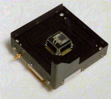
10 10
11 5.) Gyroscope ( 1) : Vendor: B E I -T E C H., I N C. SYSTRON DONNER INERTIAL DIVISION Part : Model QRS11Micromachined Angular Rate Sensor 11
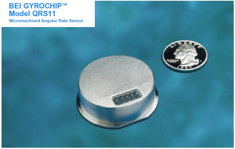
12 1
13 13

14 5.3) Accelerometer ( 1) : Vendor: PCB PIEZOTRONICS Part : 356B07 Low-Noise Triaxial ICP Accelerometer 14
15 15
16 6) ADCS Cost Estimation: The following table represent the actual and estimated component costs Component Unit Price ($) Number of parts Sun Sensor 0000 (estimated) Gyroscope 450 (actual) 1 Accelerometer 1100 (actual) 1 Nutation Damper 1000 (estimated) 1 Total = $ 7) Two Burn Thrusting Scheme A very good way of providing directional stability for spacecraft and rockets is to spin them about their maximum or minimum principal axes. We know from dynamic analysis of rigid bodies that the angular momentum of a spinning rigid body will remain constant unless acted upon an external torque. Due to production tolerances, small errors in the thruster location and direction are inevitable. Therefore an axially thrusting-spinning spacecraft or rocket will experience unwanted transverse torques during the thrusting maneuver 1, as shown in figure 1. In the FIG. 1 Thrusting Problem example configuration thruster offset causes a body fixed torque in to the page. We know that such a torque will distort the angular momentum vector in inertial coordinates and cause it to trace a circular path as it is shown in figure. The average angular momentum bias angle ρ is measured from the vertical and in the YZ plane, as shown in the 1 Longuski J.M., T. Kia, W.G. Breckenridge, Annihilation of Angular Momentum Bias During Thrusting and Spinning-up Maneuvers, The Journal of the Astronautical Sciences, Vol. 37, No.4, October-December 1989, pp
17 reference 1 and it is shown that the V pointing errors occur along the axis set by ρ in axially thrusting spin-stabilized spacecraft and rockets. In the figure, H o shows the initial position of the angular momentum vector and the H vector is the angular momentum during the thrusting maneuver. FIG. The Angular Momentum and Velocity Pointing Bias During Thrusting A remedy for the problem lies in using a two-burn scheme as proposed 1.And indeed, this method is the simplest and probably most effective way of achieving a solution, provided that we have an on-off type pulse thruster. With the conclusion that that the velocity pointing error will occur along the direction set by the angular momentum bias, then the basic idea lies behind eliminating the angular momentum bias. We know that for the case of spinning and axially thrusting spacecraft with the presence of thruster offset, there is no way of eliminating the angular momentum bias except highly sophisticated controllers. However, with the two-burn scheme proposed by Longuski et al. 1 it is possible to eliminate the time average of the angular momentum bias. The idea is to shift the center of the circle that is traced by the angular momentum vector to the origin of the inertial axis system as shown in figure 3 below. FIG. 3 Initial and Final Paths of the Angular Momentum Vector in Two Burn Scheme Uncompensated angular momentum vector moves on the depicted initial angular momentum path. When the angular momentum vector comes to the point A in the figure 3, along the solid line, the thruster is turned off (coasting) and consequently the angular Longuski J.M., T. Kia, W.G. Breckenridge, Annihilation of Angular Momentum Bias During Thrusting and Spinning-up Maneuvers, The Journal of the Astronautical Sciences, Vol. 37, No.4, October-December 1989, pp

18 momentum vector stops moving since there is no external torques acting on the spacecraft. The A point corresponds to a 60 o rotation of the spacecraft and the time required to arrive this point can be found simply from the relation t b = π / 3Ω, where, t b denotes 1 st burn time and Ω is the spin rate. We note that if we define θ as the spacecraft rotation angle, the time relation of it is simply θ = Ω t After the first ignition, the thruster is kept off for a period of coast time t c = π / 3Ω and after that it is ignited again for the rest of the maneuver. In the end this causes the angular momentum vector to fall in the track of the final path shown in dashed lines, which has an average angular momentum bias of 0 degrees. The resulting behavior of the velocity pointing error and angular momentum path can be obtained numerically using the designed spacecraft parameters (MOI, thrust and an intentional offset value of 5 cm). The promise of the two burn-scheme is evident from the plots given for numerical simulations. Simulations were performed for 180 seconds (3 minutes). FIG. 4 Simulation of Angular Momentum Path and Velocity Path without the Two-Burn Scheme 18

19 FIG. 5 Simulation of Angular Momentum Path and Velocity Path with the Two-Burn Scheme According to the numerical results, the spacecraft departed about 1. m laterally during 3 minute thrusting using the two-burn scheme as compared to the approximately 1 m lateral departure of the single-burn case. 19
Burn Baby Burn Gina Covarrubias John Dankanich Kristin Gates Jon Mah Mike Schreiner Selim Solmaz
 Burn Baby Burn Gina Covarrubias Kristin Gates Mike Schreiner John Dankanich Jon Mah Selim Solmaz Executive Summary The Burn Baby Burn satellite system is a university built satellite. The manufacturing
AS3010: Introduction to Space Technology
 AS3010: Introduction to Space Technology L E C T U R E 22 Part B, Lecture 22 19 April, 2017 C O N T E N T S Attitude stabilization passive and active. Actuators for three axis or active stabilization.
Attitude Determination and. Attitude Control
 Attitude Determination and Placing the telescope in orbit is not the end of the story. It is necessary to point the telescope towards the selected targets, or to scan the selected sky area with the telescope.
CHAPTER 3 PERFORMANCE
 PERFORMANCE 3.1 Introduction The LM-3A performance figures given in this chapter are based on the following assumptions: Launching from XSLC (Xichang Satellite Launch Center, Sichuan Province, China),
CHAPTER 3 PERFORMANCE
 PERFORMANCE 3.1 Introduction The LM-3B performance figures given in this chapter are based on the following assumptions: Launching from XSLC (Xichang Satellite Launch Center, Sichuan Province, China),
5.12 The Aerodynamic Assist Trajectories of Vehicles Propelled by Solar Radiation Pressure References...
 1 The Two-Body Problem... 1 1.1 Position of the Problem... 1 1.2 The Conic Sections and Their Geometrical Properties... 12 1.3 The Elliptic Orbits... 20 1.4 The Hyperbolic and Parabolic Trajectories...
Satellite Components & Systems. Dr. Ugur GUVEN Aerospace Engineer (P.hD) Nuclear Science & Technology Engineer (M.Sc)
 Nuclear Science & Technology Engineer (M.Sc)") Satellite Components & Systems Dr. Ugur GUVEN Aerospace Engineer (P.hD) Nuclear Science & Technology Engineer (M.Sc) Definitions Attitude: The way the satellite is inclined toward Earth at a certain inclination
Satellite Components & Systems Dr. Ugur GUVEN Aerospace Engineer (P.hD) Nuclear Science & Technology Engineer (M.Sc) Definitions Attitude: The way the satellite is inclined toward Earth at a certain inclination
The Interstellar Boundary Explorer (IBEX) Mission Design: A Pegasus Class Mission to a High Energy Orbit
 Mission Design: A Pegasus Class Mission to a High Energy Orbit") The Interstellar Boundary Explorer (IBEX) Mission Design: A Pegasus Class Mission to a High Energy Orbit Ryan Tyler, D.J. McComas, Howard Runge, John Scherrer, Mark Tapley 1 IBEX Science Requirements IBEX
The Interstellar Boundary Explorer (IBEX) Mission Design: A Pegasus Class Mission to a High Energy Orbit Ryan Tyler, D.J. McComas, Howard Runge, John Scherrer, Mark Tapley 1 IBEX Science Requirements IBEX
AN ANALYTICAL SOLUTION TO QUICK-RESPONSE COLLISION AVOIDANCE MANEUVERS IN LOW EARTH ORBIT
 AAS 16-366 AN ANALYTICAL SOLUTION TO QUICK-RESPONSE COLLISION AVOIDANCE MANEUVERS IN LOW EARTH ORBIT Jason A. Reiter * and David B. Spencer INTRODUCTION Collision avoidance maneuvers to prevent orbital
CHAPTER 3 PERFORMANCE
 PERFORMANCE The launch performance given in this chapter is based on the following assumptions: The LV system parameters being all nominal values; Mass of the LV adapter and the separation system are included
Spinning Satellites Examples. ACS: Gravity Gradient. ACS: Single Spin
 Attitude Determination and Attitude Control Placing the telescope in orbit is not the end of the story. It is necessary to point the telescope towards the selected targets, or to scan the selected sky
AS3010: Introduction to Space Technology
 AS3010: Introduction to Space Technology L E C T U R E S 8-9 Part B, Lectures 8-9 23 March, 2017 C O N T E N T S In this lecture, we will look at factors that cause an orbit to change over time orbital
Generation X. Attitude Control Systems (ACS) Aprille Ericsson Dave Olney Josephine San. July 27, 2000
 Aprille Ericsson Dave Olney Josephine San. July 27, 2000") Generation X Attitude Control Systems (ACS) Aprille Ericsson Dave Olney Josephine San July 27, 2000 ACS Overview Requirements Assumptions Disturbance Torque Assessment Component and Control Mode Recommendations
Generation X Attitude Control Systems (ACS) Aprille Ericsson Dave Olney Josephine San July 27, 2000 ACS Overview Requirements Assumptions Disturbance Torque Assessment Component and Control Mode Recommendations
Section 13. Orbit Perturbation. Orbit Perturbation. Atmospheric Drag. Orbit Lifetime
 Section 13 Orbit Perturbation Orbit Perturbation A satellite s orbit around the Earth is affected by o Asphericity of the Earth s gravitational potential : Most significant o Atmospheric drag : Orbital
Space mission environments: sources for loading and structural requirements
 Space structures Space mission environments: sources for loading and structural requirements Prof. P. Gaudenzi Università di Roma La Sapienza, Rome Italy paolo.gaudenzi@uniroma1.it 1 THE STRUCTURAL SYSTEM
Lecture Module 5: Introduction to Attitude Stabilization and Control
 1 Lecture Module 5: Introduction to Attitude Stabilization and Control Lectures 1-3 Stability is referred to as a system s behaviour to external/internal disturbances (small) in/from equilibrium states.
BUILDING LOW-COST NANO-SATELLITES: THE IMPORTANCE OF A PROPER ENVIRONMENTAL TESTS CAMPAIGN. Jose Sergio Almeida INPE (Brazil)
") BUILDING LOW-COST NANO-SATELLITES: THE IMPORTANCE OF A PROPER ENVIRONMENTAL TESTS CAMPAIGN Jose Sergio Almeida INPE (Brazil) 1 st International Academy of Astronautics Latin American Symposium on Small
BUILDING LOW-COST NANO-SATELLITES: THE IMPORTANCE OF A PROPER ENVIRONMENTAL TESTS CAMPAIGN Jose Sergio Almeida INPE (Brazil) 1 st International Academy of Astronautics Latin American Symposium on Small
1. (a) Describe the difference between over-expanded, under-expanded and ideallyexpanded
 Describe the difference between over-expanded, under-expanded and ideallyexpanded") Code No: R05322106 Set No. 1 1. (a) Describe the difference between over-expanded, under-expanded and ideallyexpanded rocket nozzles. (b) While on its way into orbit a space shuttle with an initial mass
Code No: R05322106 Set No. 1 1. (a) Describe the difference between over-expanded, under-expanded and ideallyexpanded rocket nozzles. (b) While on its way into orbit a space shuttle with an initial mass
End of Life Re-orbiting The Meteosat-5 Experience
 End of Life Re-orbiting The Meteosat-5 Experience Milan EUMETSAT, Darmstadt, Germany This article illustrates the orbit maneuver sequence performed during Meteosat- 5 End of Life (EOL) re-orbiting operations
Spacecraft Bus / Platform
 Spacecraft Bus / Platform Propulsion Thrusters ADCS: Attitude Determination and Control Subsystem Shield CDH: Command and Data Handling Subsystem Payload Communication Thermal Power Structure and Mechanisms
Attitude Control Simulator for the Small Satellite and Its Validation by On-orbit Data of QSAT-EOS
 SSC17-P1-17 Attitude Control Simulator for the Small Satellite and Its Validation by On-orbit Data of QSAT-EOS Masayuki Katayama, Yuta Suzaki Mitsubishi Precision Company Limited 345 Kamikmachiya, Kamakura
Satellite Orbital Maneuvers and Transfers. Dr Ugur GUVEN
 Satellite Orbital Maneuvers and Transfers Dr Ugur GUVEN Orbit Maneuvers At some point during the lifetime of most space vehicles or satellites, we must change one or more of the orbital elements. For example,
How Small Can a Launch Vehicle Be?
 UCRL-CONF-213232 LAWRENCE LIVERMORE NATIONAL LABORATORY How Small Can a Launch Vehicle Be? John C. Whitehead July 10, 2005 41 st AIAA/ASME/SAE/ASEE Joint Propulsion Conference and Exhibit Tucson, AZ Paper
BravoSat: Optimizing the Delta-V Capability of a CubeSat Mission. with Novel Plasma Propulsion Technology ISSC 2013
 BravoSat: Optimizing the Delta-V Capability of a CubeSat Mission with Novel Plasma Propulsion Technology Sara Spangelo, NASA JPL, Caltech Benjamin Longmier, University of Michigan Interplanetary Small
Pointing Control for Low Altitude Triple Cubesat Space Darts
 Pointing Control for Low Altitude Triple Cubesat Space Darts August 12 th, 2009 U.S. Naval Research Laboratory Washington, D.C. Code 8231-Attitude Control System James Armstrong, Craig Casey, Glenn Creamer,
D-SAT Simplified Magnetic Attitude Control
 D-SAT Simplified Magnetic Attitude Control Warren K. Soh, Norhizam Hamzah, Ahmad Sabirin Arshad Astronautic Technology (M) Sdn. Bhd. (ATSB) Suite G1A, Enterprise 3, Technology Park Malaysia, Bukit Jalil
HYPER Industrial Feasibility Study Final Presentation Orbit Selection
 Industrial Feasibility Study Final Presentation Orbit Selection Steve Kemble Astrium Ltd. 6 March 2003 Mission Analysis Lense Thiring effect and orbit requirements Orbital environment Gravity Atmospheric
A Concept of Nanosatellite Small Fleet for Earth Observation
 A Concept of Nanosatellite Small Fleet for Earth Observation Prof. Janusz Narkiewicz jnark@meil.pw.edu.pl Sebastian Topczewski stopczewski@meil.pw.edu.pl Mateusz Sochacki msochacki@meil.pw.edu.pl 10-11
Attitude Control Strategy for HAUSAT-2 with Pitch Bias Momentum System
 SSC06-VII-5 Attitude Control Strategy for HAUSAT-2 with Pitch Bias Momentum System Young-Keun Chang, Seok-Jin Kang, Byung-Hoon Lee, Jung-on Choi, Mi-Yeon Yun and Byoung-Young Moon School of Aerospace and
LAUNCH SYSTEMS. Col. John Keesee. 5 September 2003
 LAUNCH SYSTEMS Col. John Keesee 5 September 2003 Outline Launch systems characteristics Launch systems selection process Spacecraft design envelope & environments. Each student will Lesson Objectives Understand
Overview of the Current Baseline of the Solar-C Spacecraft System
 Overview of the Current Baseline of the Solar-C Spacecraft System Keisuke YOSHIHARA (JAXA) 11 November, 2013 Solar-C Science Meeting Hida Earth Wisdom Center, Takayama, Japan Solar-C Spacecraft System
FIBER OPTIC GYRO-BASED ATTITUDE DETERMINATION FOR HIGH- PERFORMANCE TARGET TRACKING
 FIBER OPTIC GYRO-BASED ATTITUDE DETERMINATION FOR HIGH- PERFORMANCE TARGET TRACKING Elias F. Solorzano University of Toronto (Space Flight Laboratory) Toronto, ON (Canada) August 10 th, 2016 30 th AIAA/USU
The Torque Rudder: A Novel Semi-Passive Actuator for Small Spacecraft Attitude Control
 The Torque Rudder: A Novel Semi-Passive Actuator for Small Spacecraft Attitude Control Grant Bonin, Vincent Tarantini, Luke Stras, and Robert E. Zee UTIAS Space Flight Laboratory Toronto, On. Canada M3H
Jitter and Basic Requirements of the Reaction Wheel Assembly in the Attitude Control System
 Jitter and Basic Requirements of the Reaction Wheel Assembly in the Attitude Control System Lulu Liu August, 7 1 Brief Introduction Photometric precision is a major concern in this space mission. A pointing
3D Pendulum Experimental Setup for Earth-based Testing of the Attitude Dynamics of an Orbiting Spacecraft
 3D Pendulum Experimental Setup for Earth-based Testing of the Attitude Dynamics of an Orbiting Spacecraft Mario A. Santillo, Nalin A. Chaturvedi, N. Harris McClamroch, Dennis S. Bernstein Department of
Experimental Analysis of Low Earth Orbit Satellites due to Atmospheric Perturbations
 Experimental Analysis of Low Earth Orbit Satellites due to Atmospheric Perturbations Aman Saluja #1, Manish Bansal #2, M Raja #3, Mohd Maaz #4 #Aerospace Department, University of Petroleum and Energy
Orbit Design Marcelo Suárez. 6th Science Meeting; Seattle, WA, USA July 2010
 Orbit Design Marcelo Suárez Orbit Design Requirements The following Science Requirements provided drivers for Orbit Design: Global Coverage: the entire extent (100%) of the ice-free ocean surface to at
PRELIMINARY HARDWARE DESIGN OF ATTITUDE CONTROL SUBSYSTEM OF LEONIDAS SPACECRAFT
 PRELIMINARY HARDWARE DESIGN OF ATTITUDE CONTROL SUBSYSTEM OF LEONIDAS SPACECRAFT Chak Shing Jackie Chan College of Engineering University of Hawai i at Mānoa Honolulu, HI 96822 ABSTRACT In order to monitor
The time period while the spacecraft is in transit to lunar orbit shall be used to verify the functionality of the spacecraft.
 ASE 379L Group #2: Homework #4 James Carlson Due: Feb. 15, 2008 Henri Kjellberg Leah Olson Emily Svrcek Requirements The spacecraft shall be launched to Earth orbit using a launch vehicle selected by the
arxiv:gr-qc/ v1 15 Nov 2004
 Mission design for LISA Pathfinder arxiv:gr-qc/0411071v1 15 Nov 2004 M Landgraf, M Hechler, and S Kemble ESA/ESOC, Robert-Bosch-Straße 5, D-64293 Darmstadt, Germany E-mail: Markus.Landgraf@esa.int EADS
Dynamics and Control Functional Division Report
 Dynamics and Control Functional Division Report Jon Chrone Kevin Daugherty Jeremy Davis Kevin Earle Josh Ellis Mark Grigg Bhalvinder Gulati Becky Maiorano Ellen McDorman Josh Michener November 18, 2004
Rapid De-Orbit of LEO Space Vehicles Using Towed Rigidizable Inflatable Structure (TRIS) Technology: Concept and Feasibility Assessment
 Technology: Concept and Feasibility Assessment") Rapid De-Orbit of LEO Space Vehicles Using Towed Rigidizable Inflatable Structure (TRIS) Technology: Concept and Feasibility Assessment Submitted to: AIAA Small Satellite Conference August 2004 Ball Aerospace
Rapid De-Orbit of LEO Space Vehicles Using Towed Rigidizable Inflatable Structure (TRIS) Technology: Concept and Feasibility Assessment Submitted to: AIAA Small Satellite Conference August 2004 Ball Aerospace
LAUNCHES AND LAUNCH VEHICLES. Dr. Marwah Ahmed
 LAUNCHES AND LAUNCH VEHICLES Dr. Marwah Ahmed Outlines 2 Video (5:06 min) : https://youtu.be/8t2eyedy7p4 Introduction Expendable Launch Vehicles (ELVs) Placing Satellite into GEO Orbit Introduction 3 Introduction
Attitude control system for ROCSAT-3 microsatellite: a conceptual design
 Acta Astronautica 56 (5) 9 5 www.elsevier.com/locate/actaastro Attitude control system for ROCSAT- microsatellite: a conceptual design Y.W. Jan a;b; ;, J.C. Chiou b; a National Space Program Oce, Hsinchu,
Proton Launch System Mission Planner s Guide SECTION 2. LV Performance
 Proton Launch System Mission Planner s Guide SECTION 2 LV Performance 2. LV PERFORMANCE 2.1 OVERVIEW This section provides the information needed to make preliminary performance estimates for the Proton
DARE Mission and Spacecraft Overview
 DARE Mission and Spacecraft Overview October 6, 2010 Lisa Hardaway, PhD Mike Weiss, Scott Mitchell, Susan Borutzki, John Iacometti, Grant Helling The information contained herein is the private property
Satellite Attitude Control System Design Using Reaction Wheels Bhanu Gouda Brian Fast Dan Simon
 Satellite Attitude Control System Design Using Reaction Wheels Bhanu Gouda Brian Fast Dan Simon Outline 1. Overview of Attitude Determination and Control system. Problem formulation 3. Control schemes
INTERNAL THALES ALENIA SPACE
 Workshop Galileo Galilei (GG) and GGG lab prototype: state of the art and new possibilities Template reference : 100181670S-EN GG error budget from the end-to-end simulator developed at TAS-I Giuseppe
GP-B Attitude and Translation Control. John Mester Stanford University
 GP-B Attitude and Translation Control John Mester Stanford University 1 The GP-B Challenge Gyroscope (G) 10 7 times better than best 'modeled' inertial navigation gyros Telescope (T) 10 3 times better
The post launch assessment review confirmed the following previous assertions about the mission status:
 1 GRACE Newsletter No. 2 August 15, 2003 Topics: http://www.csr.utexas/grace/ http://www.gfz-potsdam.de/grace 1. Editorial 2. Major events in Mission Operations since last Newsletter 3. Current status
Astromechanics. 6. Changing Orbits
 Astromechanics 6. Changing Orbits Once an orbit is established in the two body problem, it will remain the same size (semi major axis) and shape (eccentricity) in the original orbit plane. In order to
Infrared Earth Horizon Sensors for CubeSat Attitude Determination
 Infrared Earth Horizon Sensors for CubeSat Attitude Determination Tam Nguyen Department of Aeronautics and Astronautics Massachusetts Institute of Technology Outline Background and objectives Nadir vector
Spacecraft Attitude Dynamics for Undergraduates
 Session 1123 Spacecraft Attitude Dynamics for Undergraduates Dr. Rachel Shinn Embry Riddle Aeronautical University, Prescott, AZ Abstract Teaching spacecraft attitude dynamics to undergraduate students
Chapter 8 Part 1. Attitude Dynamics: Disturbance Torques AERO-423
 Chapter 8 Part 1 Attitude Dynamics: Disturbance Torques AEO-43 Types of Disturbance Torques Solar Pressure Dominant torque for geosynchronous satellites Gravity Gradient Can be disturbance or control torque
AMSAT Phase IV Propulsion and Attitude Control Systems Conceptual Design Doug May Thiokol Corporation
 AMSAT Phase V Propulsion and Attitude Control Systems Conceptual Design Doug May Thiokol Corporation Amateur Radio Satellite Corporation (AMSAT) is developing a satellite designated Phase V for operation
HYPER Feasibility Study
 B Page 1 of 126 Hyper Initial Feasibility Orbit Trade-Off Report HYP-1-01 Prepared by: Date: September2002 Stephen Kemble Checked by: Date: September 2002 Stephen Kemble Authorised by: Date: September2002
The Orbit Control of ERS-1 and ERS-2 for a Very Accurate Tandem Configuration
 The Orbit Control of ERS-1 and ERS-2 for a Very Accurate Tandem Configuration Mats Rosengren European Space Operations Centre Robert Bosch Str 5 D64293 Darmstadt Germany Email: mrosengr@esoc.esa.de Abstract
MAE 180A: Spacecraft Guidance I, Summer 2009 Homework 4 Due Thursday, July 30.
 MAE 180A: Spacecraft Guidance I, Summer 2009 Homework 4 Due Thursday, July 30. Guidelines: Please turn in a neat and clean homework that gives all the formulae that you have used as well as details that
Passive Magnetic Attitude Control for CubeSat Spacecraft
 Passive Magnetic Attitude Control for CubeSat Spacecraft David Gerhardt Advisor: Dr. Scott Palo University of Colorado at Boulder Department of Aerospace Engineering Sciences August 11, 2010 Motivation
Technology Readiness Level:
 Technology Readiness Level: We plan to raise the TRL of the model with an acceleration noise performance requirement of < 10-12 m sec -2 Hz -1/2 at frequencies between 1 mhz and 1 Hz, from TRL 3 to TRL
The Simplest Tether Control Law in a Small Satellite
 The Simplest Tether Control Law in a Small Satellite Yosuke Nakamura (Kyushu University) Designing of a small satellite based on the Satellite Design Contest is progressing in Kyushu University. This is
Lecture D30 - Orbit Transfers
 J. Peraire 16.07 Dynamics Fall 004 Version 1.1 Lecture D30 - Orbit Transfers In this lecture, we will consider how to transfer from one orbit, or trajectory, to another. One of the assumptions that we
INNOVATIVE STRATEGY FOR Z9 REENTRY
 INNOVATIVE STRATEGY FOR Z9 REENTRY Gregor Martens*, Elena Vellutini**, Irene Cruciani* *ELV, Corso Garibaldi, 34 Colleferro (Italy) **Aizoon, Viale Città d Europa 681, 144, Roma (Italy) Abstract Large
Creating Large Space Platforms From Small Satellites
 SSC99-VI-6 Creating Large Space Platforms From Small Satellites Andrew W. Lewin Principal Systems Engineer Orbital Sciences Corporation Dulles, VA 20166 (703) 406-5000 lewin.andy@orbital.com Abstract.
PROBA 1. F. Teston ESA/ESTEC D/TEC-EL
 PROBA 1 F. Teston ESA/ESTEC D/TEC-EL Frederic.Teston@esa.int PROBA 1 launch PROBA 1 has been launched on 21 October 2001 Orbital parameters: Altitude: 681-561 km Near polar (inclination of 97.9 ) Sun-synchronous
Infrared Earth Horizon Sensors for CubeSat Attitude Determination
 Infrared Earth Horizon Sensors for CubeSat Attitude Determination Tam Nguyen Department of Aeronautics and Astronautics Massachusetts Institute of Technology Outline Background and objectives Nadir vector
NAVIGATION & MISSION DESIGN BRANCH
 c o d e 5 9 5 National Aeronautics and Space Administration Michael Mesarch Michael.A.Mesarch@nasa.gov NAVIGATION & MISSION DESIGN BRANCH www.nasa.gov Outline Orbital Elements Orbital Precession Differential
Attitude Determination using Infrared Earth Horizon Sensors
 SSC14-VIII-3 Attitude Determination using Infrared Earth Horizon Sensors Tam Nguyen Department of Aeronautics and Astronautics, Massachusetts Institute of Technology 77 Massachusetts Avenue, Cambridge,
System engineering approach toward the problem of required level of in-orbit autonomousoperation of a LEO microsatellite mission
 System engineering approach toward the problem of required level of in-orbit autonomousoperation of a LEO microsatellite mission H.Bonyan Amirkabir University of Technology (AUT) H.Bonyan@dena.aut.ac.ir
A Regional Microsatellite Constellation with Electric Propulsion In Support of Tuscan Agriculture
 Berlin, 20 th - 24 th 2015 University of Pisa 10 th IAA Symposium on Small Satellites for Earth Observation Student Conference A Regional Microsatellite Constellation with Electric Propulsion In Support
CHAPTER 5 FUZZY LOGIC FOR ATTITUDE CONTROL
 104 CHAPTER 5 FUZZY LOGIC FOR ATTITUDE CONTROL 5.1 INTRODUCTION Fuzzy control is one of the most active areas of research in the application of fuzzy set theory, especially in complex control tasks, which
Mechanical and Thermal Design of XMM
 r bulletin 100 december 1999 Mechanical and Thermal Design of XMM K. van Katwijk, T. van der Laan & D. Stramaccioni XMM Project, ESA Directorate for Scientific Programmes, ESTEC, Noordwijk, The Netherlands
PHYSICS 218 FINAL EXAM Fall, 2005 Sections
 PHYSICS 218 FINAL EXAM Fall, 2005 Sections 807-809 Name: Signature: Student ID: E-mail: Section Number: You have the full class period to complete the exam. Formulae are provided on the last page. You
Power, Propulsion, and Thermal Preliminary Design Review James Black Matt Marcus Grant McLaughlin Michelle Sultzman
 Power, Propulsion, and Thermal Preliminary Design Review James Black Matt Marcus Grant McLaughlin Michelle Sultzman Outline 1. Crew Systems Design Selection 2. Thermal Requirements and Design 3. Power
ASEN 6008: Interplanetary Mission Design Lab Spring, 2015
 ASEN 6008: Interplanetary Mission Design Lab Spring, 2015 Lab 4: Targeting Mars using the B-Plane Name: I d like to give credit to Scott Mitchell who developed this lab exercise. He is the lead Astrodynamicist
Sail-Assisted End-of-Life Disposal of High-LEO Satellites
 4th International Symposium on Solar Sailing Kyoto, Japan, January 17-20, 2017 Sail-Assisted End-of-Life Disposal of High-LEO Satellites Sergey Trofimov Keldysh Institute of Applied Mathematics Russian
Experiment Design and Performance. G. Catastini TAS-I (BUOOS)
") Experiment Design and Performance G. Catastini TAS-I (BUOOS) 10 EP and the GRT Einstein s General Relativity Theory Weak Equivalence Principle: all test particles at the same space-time point in a given
Experiment Design and Performance G. Catastini TAS-I (BUOOS) 10 EP and the GRT Einstein s General Relativity Theory Weak Equivalence Principle: all test particles at the same space-time point in a given
USA Space Debris Environment, Operations, and Policy Updates
 USA Space Debris Environment, Operations, and Policy Updates Presentation to the 48 th Session of the Scientific and Technical Subcommittee Committee on the Peaceful Uses of Outer Space United Nations
Design of Sliding Mode Attitude Control for Communication Spacecraft
 Design of Sliding Mode Attitude Control for Communication Spacecraft Erkan Abdulhamitbilal 1 and Elbrous M. Jafarov 1 ISTAVIA Engineering, Istanbul Aeronautics and Astronautics Engineering, Istanbul Technical
APPENDIX B SUMMARY OF ORBITAL MECHANICS RELEVANT TO REMOTE SENSING
 APPENDIX B SUMMARY OF ORBITAL MECHANICS RELEVANT TO REMOTE SENSING Orbit selection and sensor characteristics are closely related to the strategy required to achieve the desired results. Different types
ADCSS 2017: Sodern presentation
 ADCSS 2017: Sodern presentation 1 Agenda Star trackers road map: a wide range of products End of CCD star trackers: SED26 replaced by Horus as standalone multi mission star tracker Hydra maintained beyond
Pico-Satellite Orbit Control by Vacuum Arc Thrusters as Enabling Technology for Formations of Small Satellites
 1/25 Pico-Satellite Orbit Control by Vacuum Arc Thrusters as Enabling Technology for Formations of Small Satellites Igal Kronhaus, Mathias Pietzka, Klaus Schilling, Jochen Schein Department of Computer
From an experimental idea to a satellite
 From an experimental idea to a satellite Hansjörg Dittus Institute of Space Systems, Bremen German Aerospace Center Looking back in History Yukawa potential Gravity at large scales Weak gravity Nordtvedt
ATTITUDE CONTROL MECHANIZATION TO DE-ORBIT SATELLITES USING SOLAR SAILS
 IAA-AAS-DyCoSS2-14-07-02 ATTITUDE CONTROL MECHANIZATION TO DE-ORBIT SATELLITES USING SOLAR SAILS Ozan Tekinalp, * Omer Atas INTRODUCTION Utilization of solar sails for the de-orbiting of satellites is
Attitude Determination and Control System Design for STU-2A Cubesat and In-Orbit Results
 13 th Annual Summer CubeSat Developer s Workshop August 6-7, 2016, Logan, Utah Attitude Determination and Control System Design for STU-2A Cubesat and In-Orbit Results Presented by Shufan Wu Guowen Sun,
The Quantum Sensor Challenge Designing a System for a Space Mission. Astrid Heske European Space Agency The Netherlands
 The Quantum Sensor Challenge Designing a System for a Space Mission Astrid Heske European Space Agency The Netherlands Rencontres de Moriond - Gravitation, La Thuile, 2017 Quantum Sensors in Lab Experiments
TRAJECTORY SIMULATIONS FOR THRUST-VECTORED ELECTRIC PROPULSION MISSIONS
 RAJECORY SIMULAIONS FOR HRUS-VECORED ELECRIC PROPULSION MISSIONS Abstract N. Leveque, C. Welch, A. Ellery, A. Curley Kingston University, Astronautics and Space Systems Group School of Engineering Friars
Ball Aerospace & Technologies Corp. & L Garde Inc.
 Ball Aerospace & Technologies Corp. & L Garde Inc. Rapid De-Orbit of LEO Space Vehicles Using Towed owed Rigidizable Inflatable nflatable Structure tructure (TRIS) Technology: Concept and Feasibility Assessment
On Sun-Synchronous Orbits and Associated Constellations
 On Sun-Synchronous Orbits and Associated Constellations Daniele Mortari, Matthew P. Wilkins, and Christian Bruccoleri Department of Aerospace Engineering, Texas A&M University, College Station, TX 77843,
Toshinori Kuwahara*, Yoshihiro Tomioka, Yuta Tanabe, Masato Fukuyama, Yuji Sakamoto, Kazuya Yoshida, Tohoku University, Japan
 Toshinori Kuwahara*, Yoshihiro Tomioka, Yuta Tanabe, Masato Fukuyama, Yuji Sakamoto, Kazuya Yoshida, Tohoku University, Japan The 3 rd Nano-Satellite Symposium Micro/Nano Satellite & Debris Issues December
Presentation by Indian Delegation. to 49 th STSC UNCOPUOS. February 2012 Vienna
 Presentation by Indian Delegation to 49 th STSC UNCOPUOS February 2012 Vienna ASTROSAT Astrosat is India s first dedicated multiwavelength astronomy satellite with a capability to observe target sources
Concordia University Department of Electrical and Computer Engineering Fundamentals of Control Systems (ELEC372) S. Hashtrudi Zad
 S. Hashtrudi Zad") Concordia University Department of Electrical and Computer Engineering Fundamentals of Control Systems (ELEC372) S. Hashtrudi Zad Project: Analysis of the Performance of a Satellite Pitch Control System
Concordia University Department of Electrical and Computer Engineering Fundamentals of Control Systems (ELEC372) S. Hashtrudi Zad Project: Analysis of the Performance of a Satellite Pitch Control System
Statistical methods to address the compliance of GTO with the French Space Operations Act
 Statistical methods to address the compliance of GTO with the French Space Operations Act 64 th IAC, 23-27 September 2013, BEIJING, China H.Fraysse and al. Context Space Debris Mitigation is one objective
Rocket Science 102 : Energy Analysis, Available vs Required
 Rocket Science 102 : Energy Analysis, Available vs Required ΔV Not in Taylor 1 Available Ignoring Aerodynamic Drag. The available Delta V for a Given rocket burn/propellant load is ( ) V = g I ln 1+ P
Design and Implementation of a Space Environment Simulation Toolbox for Small Satellites
 56th International Astronautical Congress 25 35th Student Conference (IAF W.) IAC-5-E2.3.6 Design and Implementation of a Space Environment Simulation Toolbox for Small Satellites Rouzbeh Amini, Jesper
PRELIMINAJ3.:( 6/8/92 SOFTWARE REQUIREMENTS SPECIFICATION FOR THE DSPSE GUIDANCE, NAVIGATION, AND CONTROL CSCI. Prepared by
 PRELIMINAJ3.:( SOFTWARE REQUIREMENTS SPECIFICATION FOR THE DSPSE GUIDANCE, NAVIGATION, AND CONTROL CSCI Prepared by Space Applications Corporation 6/8/92.. 1 SCOPE 1.1 IDENTIFICATION 1.2 OVERVIEW This
Powered Space Flight
 Powered Space Flight KOIZUMI Hiroyuki ( 小泉宏之 ) Graduate School of Frontier Sciences, Department of Advanced Energy & Department of Aeronautics and Astronautics ( 基盤科学研究系先端エネルギー工学専攻, 工学系航空宇宙工学専攻兼担 ) Scope
Venus Express Aerobraking and End of Mission
 Venus Express Aerobraking and End of Mission Håkan Svedhem ESA/ESTEC Pericentre velocity vs Orbital Period Examples (VEX): Delta-V needed for Reduction of orbital period: 24h-18h 90m/s 18h-16h 42m/s 18h-12h
Proton Launch System Mission Planner s Guide APPENDIX F. Proton Launch System Options and Enhancements
 Proton Launch System Mission Planner s Guide APPENDIX F Proton Launch System Options and Enhancements F. PROTON LAUNCH SYSTEM OPTIONS AND ENHANCEMENTS The missions presented in the previous sections represent
AEROTHERMODYNAMIC ANALYSIS OF INNOVATIVE HYPERSONIC DEPLOYABLE REENTRY CAPSULES. Raffaele Savino University of Naples Federico II
 AEROTHERMODYNAMIC ANALYSIS OF INNOVATIVE HYPERSONIC DEPLOYABLE REENTRY CAPSULES Raffaele Savino University of Naples Federico II Objectives Show the main capabilities of deployable aero-brakes for Earth