SPECIFICATION FOR APPROVAL
|
|
|
- Frederick Payne
- 5 years ago
- Views:
Transcription
 Safety Recognized Ceramic Capacitors Part Number: SERIES Data : 2015-11-04 APPROVAL SIGNATURE: AUTHORIZED BY CHECK BY VALIDATED BY")
1 TO: No.: SPECIFICATION FOR APPROVAL Product Name : Y2(KL SERIES) Safety Recognized Ceramic Capacitors Part Number: SERIES Data : APPROVAL SIGNATURE: AUTHORIZED BY CHECK BY VALIDATED BY 承認後請寄回一份 (Please return one copy after approved) TEL: FAX: Unit No. 64, Block A, Garden Industrial Zone, Xiegang Town, Dong guan City. TEL: FAX: 審 核 制 訂 Li Shui Ying
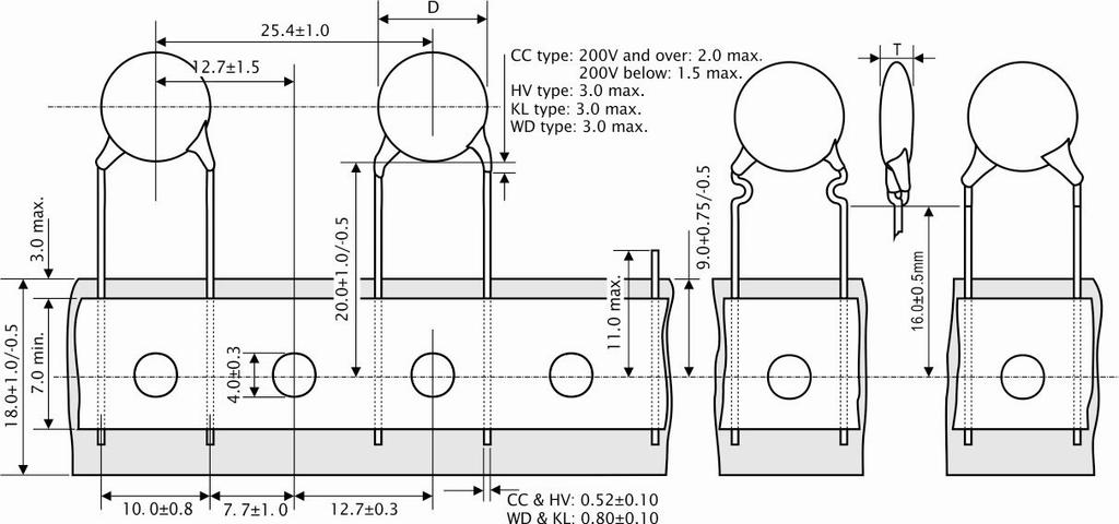
2 CONTENT Approval sheet for safety recognized ceramic capacitors 1. Purpose 1 2. Scope 1 3. Features 1 4. General specifications 2 5. chart 2 6. How to order 3 7. Specifications 4~7 8. Storage environment 7 Annex 1: Taping specifications

3 P1 / 7 1. Purpose In order to reach the recognition in the electrical characteristics and the appearance, the dimension when ensuring the samples and facilitate the specification and acceptance criteria of the follow-up goods, so we set down the standard. 2. Scope This specification applies to the capacitors of following table: No. Description Part number Customer VS P/N 1 SEE SERIES 3. Features 3.1 This product which are recognized by UL, CSA, VDE, ENEC and CQC, Its standards and certificate number in the following. Approved monogram Country Standards Rated voltage Certificate number KL(X1Y2) WD(X1Y1) KL(X1Y2) WD(X1Y1) U.S.A Canada UL Vac E Canada CAN/CSA-E Vac Germany EN (0565-1) EN IEC ED 3 X1: 440/400Vac Y2: 300/250Vac X1: 760/400Vac Y1: 500/250Vac Table A EN (0565-1) EN IEC ED 3 X1: 440/400Vac Y2: 300/250Vac X1: 760/400Vac Y1: 500/250Vac China GB/T X1: 400Vac Y2: 250Vac X1: 400Vac Y1: 250Vac CQC CQC Table A - ENEC Signatories (Please refer to AENOR (Spain) EZU (Czech Republic) NEMKO (Norway) TUV SUD PS (Germany) ASTA BEAB (United kingdom) IMQ (Italy) SGS Belgium (Belgium) UL Int DEMKO (Demark) BSI (United kingdom) Intertek Semko (Sweden) SGS FIMKO (Finland) VDE (Germany) CERTIF (Portugal) KEMA (Netherlands) SIQ (Slovenia) OVE (Austria) ELECTROSUISSE (Switzerland) LCIE (France) SNCH (Luxembourg) ELOT (Greece) MEEI (Hungary) TRPS (Germany) 3.2 Operating temperature range guaranteed up to 125 degrees. 3.3 Coated with flame-retardant epoxy resin (conforming to UL94V-0 standard), Lead with tin plated copper wire, inert metal copper or silver as a coating after the electrode, its structure follows. 3.4 Comply with RoHS. 3.5 Halogen-free available.
4 4. General specifications Characteristics WD type (X1 Y1) KL type (X1 Y2) range 1pF to 0.01uF 1pF to 0.015uF Rated voltage X1: 760/400Vac; Y1: 500/250Vac X1: 440/400Vac; Y2: 300/250Vac strength 4000Vac (50Hz-60Hz, 50mA max.) for 1 minute. 2500Vac (50Hz-60Hz, 50mA max.) for 1 minute. Within the specified tolerance. (CR) Y5P, Y5U, Y5V, X7R measured at 1kHz±20% N750, C0G, SL measured at 1MHz±20% Both are 1Vrms, 25 Dissipation Factor (tanδ) or Q Value Insulation resistance Operating temperature range N750, SL and C0G: Y5P, Y5U, X7R: Y5V: Q CR (CR<30pF) tanδ: max. tanδ: max. Q 1000 (CR 30pF) Measured condition see MΩ minimum at 500VDC for 1 minute. -25 to to 125 for C0G, N750, SL and X7R P2 / 7 5. chart PART NUMBER T.C. CAP. TOL DIMENSION(mm) D(max) T(max) F(±0.8mm) KL1P0C to 10PJ COG/SL 1PF to10pf ±2.5pfor±0.5pf KL10PK to 33PK COG/SL/Y5P 10PFto33PF ±5%or±10% /10.0 KLB101K(Y2) 100PF KLB151K(Y2) 150PF KLB221K(Y2) 220PF KLB331K(Y2) 330PF KLB471K(Y2) Y5P 470PF ±10% KLB561K(Y2) 560PF KLB681K(Y2) 680PF KLB821K(Y2) 820PF KLB102K(Y2) 1000PF KLE102M(Y2) 1000PF KLE152M(Y2) 1500PF KLE222M(Y2) 2200PF KLE332M(Y2) Y5U 3300PF ±20% KLE472M(Y2) 4700PF KLE103M(Y2) 10000PF KLE153M(Y2) 15000PF KLF102M(Y2) 1000PF KLF152M(Y2) 1500PF KLF222M(Y2) 2200PF KLF332M(Y2) 3300PF KLF472M(Y2) Y5V 4700PF ±20% KLF392M(Y2) 3900PF KLF682M(Y2) 6800PF KLF103M(Y2) 10000PF KLF153M(Y2) 15000PF
5 P3 / 7 6. How to order Example: Coding order: KL F 472 M 9 Y L 1 2 Type code: KL: class X1, Y2; WD: class X1, Y1. Temperature characteristic: Code Temp. char. Code Temp. char. Code Temp. char. 7 N750 B Y5P E Y5U S SL X X7R F Y5V 3 Nominal capacitance: Expressed by three-digit alphanumeric. The unit is pico-farad (pf). The first and second figures are significant digits, and the third figure expresses the number of zeros which follow the two numbers. If there is a decimal point, it is expressed by the capital letter P. In this case, all figures are significant digits. Code Code Code 5P1 5.1pF 10P 10pF pF 8P0 8pF pF uF 4 tolerance: Code Tolerance Code Tolerance Code Tolerance C ±0.25pF J ±5.0% M ±20% D ±0.50pF K ±10% Z +80/-20% 5 Lead spacing (F): Code Lead spacing (F) Code Lead spacing (F) 5 5.0±0.8mm ±0.8mm 6 6.5±0.8mm ±0.8mm 7 7.5±0.8mm 6 Lead style: Code H Y X W Z Lead style 7 Lead length (L) and Package style: L: long lead & bulk packaging; S: Short lead & bulk packaging; T: Taping packaging. TB: Taping Box.TR: Taping Roll

6 7. Specifications P4 / 7 Warning! Measurement, please note the following, if there is a breach may result in inaccurate measurements, and even damage to the test capacitors. 7.1 Please measurement of the ambient temperature at 25±2, relative humidity at percent among. Please test capacitor requirements placed on the ambient temperature 30 minutes or more should avoid cold / hot wind blowing straight test capacitors or other sources of heat, cold source of radiation. 7.2 When measuring, gloves, warm hands so as not to affect the test results of capacitors, and against access to live parts. 7.3 When measuring, please note that the order of measurement, the first measurement of capacitance and dissipation resistance, insulation resistance measurement, the measurement of the final test voltage. 7.4 measurement, instrumentation should be cleared. 7.5 Measurement of voltage, the test will not directly increase in the exchange of high-voltage capacitors, should be based on 150V / s rate rose from 0V voltage test, the test of time can be increased to test the voltage start time. Measuring the end of the capacitor should discharge. 7.6 Specifications No. Item Specification Testing Method 1 Appearance and Dimensions No marked defect on appearance form and dimensions are within specified range. The capacitor should be visually inspected for evidence of defect. Dimensions should be measured with slide calipers. 2 Marking To be easily legible The capacitor should be visually inspected 3 (CR) Within specified tolerance 4 Dissipation Factor (tanδ) or Q Value Char. 7, C, L Specificatons Q CR (CR<30pF) Q 1000 (CR 30pF) X, B, E tanδ: max. The capacitance and dissipation factor should be measured at 25± 1 C with 1±0.2KHz (char. 7, C & L: 1±0.2MHz) and AC5V(r.m.s.) max. F tanδ: max. 5 Insulation Resistance () 10000MΩ min. The insulation resistance should be measured with DC500±50V within 60±5 sec. of charging. The voltage should be applied to the capacitor through a resistor of 1MΩ. Between Lead Wires No failure The capacitor should not be damaged when test voltages of Table 1 are applied between the lead wires for 60 sec. (Charge/Discharge current 50mA) <Table 1> Type KL WD Test Voltage AC2500V AC4000V 6 Body Insulation No failure First, the terminals of the capacitor should be connected together. Then, as shown in figure at right, a metal foil should be closely wrapped around the body of the capacitor to the distance of about 3 to 4mm from each terminal. Then, the capacitor should be inserted into a container filled with metal balls of about 1mm diameter. Finally, AC voltage of Table 2 is applied for 60 sec. between the capacitor lead wires and metal balls. <Table 2> Type KL WD Test Voltage AC2500V AC4000V
 Soldering Effect (On -Preheat) Vibration Resistance Humidity (Under")
7 P5 / 7 No. Item Specification Testing Method 7 Temperature Characteristics 8 Solderability of Leads Soldering Effect (Non -Preheat) Soldering Effect (On -Preheat) Vibration Resistance Humidity (Under Steady State) Char. B Within ±10% X Within ±15% E Within +20/-55% F Within +30/-80% (Temp. range: -25 to +85 C) Char. Temperature Coefficient C 0±30ppm/ C 7-750±120ppm/ C L +350 to -1000ppm/ C (Temp. range: -20 to 85 C) Lead wire should be soldered with uniform coating on the axial direction over 3/4 of the circumferential direction. 7, C, L: ±5% or 1pF, whichever is large. B: ±10% X, E, F: ±20% 1000MΩ min 7, C, L: ±5% or 1pF, whichever is large. B: ±10% X, E, F: ±20% 1000MΩ min Within the specified tolerance tanδor Q Per Item 4 tanδor Q 7, C: Within ±2.5% L: Within ±5.0% X, B, E:Within ±10% F:Within ±15% Char. 7,C, L Specifications Q 275+5/2CR (CR<30pF) Q 350 (CR 30pF) X, B, E tanδ: max. F tanδ: max. The capacitance measurement should be made at each step specified in Table 3. <Table 3> Step Temperature ( ) 20±2 2-25±2 3 20±2 4 85±2 5 20±2 The lead wire of a capacitor should be dipped into molten solder for 2±0.5 sec. The depth of immersion is up to about 1.5 to 2.0mm from the root of lead wires. Temp. of solder: Lead Free Solder (Sn-3Ag-0.5Cu) 245±5 C H63 Eutectic Solder(Pb37/Sn63)235±5 C As shown in figure, the lead wires should be immersed in solder of 350±10 C or 260±5 C up to 1.5 to 2.0mm from the root of terminal for 3.5±0.5 sec. (10±1 sec. for 260±5 C). Pre-treatment: Capacitor should be stored at 85±2 C for 1 hr., and then placed at room condition for 24±2 hrs. before initial measurements. Post-treatment: Capacitor should be stored for 1 to 2 hrs. at room condition. First the capacitor should be stored at 120+0/-5 C for 60+0/-5 sec. Then, as in figure (see Item 9), the lead wires should be immersed solder of 260+0/-5 C up to 1.5 to 2.0mm from the root of terminal for 7.5+0/-1 sec. Pre-treatment and Post-treatment see Per Item 9. The capacitor should be firmly soldered to the supporting lead wire and vibrated at a frequency range of 10 to 55Hz, 1.5mm in total amplitude, with about a 1 minute rate of vibration change from 10Hz to 55Hz and back to 10Hz. Apply for a total of 6 hrs., 2 hrs each in 3 mutually perpendicular directions. Set the capacitor for 500±12 hrs. at 40±2 C in 90 to 95% relative humidity. Post-treatment: Capacitor should be stored for 1 to 2 hrs. at room condition. 3000MΩ min
8 P6 / 7 No. Item Specification Testing Method 7, C: Within ±2.5% L: Within ±5.0% X, B, E:Within ±10% F:Within ±15% 13 Humidity Loading tanδor Q Char. 7, C, L Specifications Q 275+5/2CR (CR<30pF) Q 350 (CR 30pF) X, B, E tanδ: max. Apply the rated voltage for 500±12 hrs. at 40±2 C in 90 to 95% relative humidity. Post-treatment: Capacitor should be stored for 1 to 2 hrs. at room condition. F tanδ: max. 3000MΩ min Impulse Voltage Each individual capacitor should be subjected to a 5kV (Type X1Y1: 8kV) impulses for three times. After the capacitors are applied to life test. 7, C: Within ±2.5% L: Within ±5.0% X, B, E:Within ±10% F:Within ±15% 14 Life Test Apply a voltage of Table 4 for 1000 hrs. at 125+2/-0 C, and relative humidity of 50% max. 3000MΩ min <Table 4> Applied Voltage AC425V(r.m.s.), except that once each hour the voltage is increased to AC1000V(r.m.s.) for 0.1 sec. Post-treatment: Capacitor should be stored for 1 to 2 hrs. at *room condition. 15 Flame Test The capacitor flame discontinues as follows. Cycle Time (sec.) 1 to The capacitor should be subjected to applied flame for 15 sec. and then removed for 15 sec. until 5 cycles are completed. 16 Robustness of Terminations Tensile Bending Lead wire should not be cut off. Capacitor should not be broken. As shown in the figure at right, fix the body of the capacitor and apply a tensile weight gradually to each lead wire in the radial direction of the capacitor up to 10N and keep it for 10±1 sec. Each lead wire should be subjected to 5N weight and then a 90 bend, at the point of egress, in one direction, return to original position, and then apply a 90 bend in the opposite direction at the rate of one bend in 2 to 3 sec.

9 P7 / 7 No. Item Specification Testing Method The capacitor should be individually wrapped in at least one but not more than two complete layers of cheese-cloth. The capacitor should be subjected to 20 discharges. The interval between successive discharges should be 5 sec. The UAC should be maintained for 2 min. after the last discharge. 17 Active Flammability The cheese-cloth should not be on fire. 18 Passive Flammability The burning time should not exceed 30 sec. The tissue paper should not ignite. C1, 2: 1UF±10% C3: 0.033UF±5% 10KV Ct: 3UF±5% 10KV Cx: Capacitor under test F: Fuse, Rated 10A R: 100Ω±5% Ur: Rated Voltage Ut: Voltage applied to Ct. L1 to 4: 1.5mH±20% 16A Rod core choke The capacitor under test should be held in the flame in the position which best promotes burning. Each specimen should only be exposed once to the flame. Time of exposure to flame: 30 sec. Length of flame: 12±1mm Gas burner: Length 35mm min. Inside Dia. 0.5±0.1mm Outside Dia. 0.9mm max. Gas : Butane gas Purity 95% min. The capacitor should be subjected to 5 temperature cycles, then consecutively to 2 immersion cycles. <Temperature Cycle> Step Temperature ( ) Time (min) 7, C: Within ±2.5% L: Within ±5.0% X, B, E:Within ±10% F:Within ±15% / Room temp / Temperature and Immersion Cycle tanδor Q Per Item 4 Step 4 Room temp. 3 <Immersion Cycle> Temperature Time ( ) (min) Cycle time: 5 cycle Immersion Water /-0 0±3 Clean water 3000MΩ min Salt Water Cycle time: 2 cycle Pre-treatment: Capacitor should be stored at 85±2 C for 1 hr., then placed at room condition for 24±2 hrs. Post-treatment: Capacitor should be stored for 24±2 hrs. at room condition. 8. Storage environment Do not use or store capacitors in a corrosive atmosphere, especially where chloride gas, sulfide gas, acid, alkali, salt or the like are present. And avoid exposure to moisture. Store the capacitors where the temperature and relative humidity do not exceed 5 to 40 degrees centigrade and 20 to 70%. Use capacitors within 6 months after delivered.
 (Y)")
10 (H) (X) (H) (X) (Y) (H) (X) (Y)
RELIABILITY TEST DATA SAFETY STANDARD RECOGNIZED CERAMIC CAPACITOR
 DATA No. : RTD-E76EA RELIABILITY TEST DATA SAFETY STANDARD RECOGNIZED CERAMIC CAPACITOR MURATA PN : DE2E3KH12M*** PAGE 1. INITIAL ( Cap., D.F., I.R. )... 1 2. TEMPERATURE CHARACTERISTIC... 2 3. ROBUSTNESS
High-voltage Ceramic Capacitors (DC250V-6.3kV)
") High-voltage Ceramic Capacitors (DC250V-6.kV) DEB Series (Class 2/DC1k-.15kV) Features 1. Small size and high capacitance. 2. Coated with flame-retardant epoxy resin. (equivalent to UL94V-0
High-voltage Ceramic Capacitors (DC250V-6.kV) DEB Series (Class 2/DC1k-.15kV) Features 1. Small size and high capacitance. 2. Coated with flame-retardant epoxy resin. (equivalent to UL94V-0
S P E C I F I C A T I O N S
 TO : 2009-09-14 S P E C I F I C A T I O N S PRODUCT : CERAMIC CAPACITOR MODEL : DA (X1,Y1) SERIES Manufacturer Customer WRITTEN CHECKED APPROVED WRITTEN CHECKED APPROVED 9/14 9/14 9/14 / / / DONG IL ELECTRONICS
Prosperity Dielectrics Co., Ltd. 1 ACS-1045 Rev15
 1. DESCRIPTION MLCC consists of a conducting material and electrodes. To manufacture a chip-type SMT and achieve miniaturization, high density and high efficiency, ceramic condensers are used. WTC high
Open-mode Design Capacitors
 Open-mode Design Capacitors HOW TO ORDER OP 32 B 103 K 201 C T Series Size Dielectric Capacitance Tolerance Rated voltage Termination Packaging OP=Open-mode 21=0805 (2012) 31=1206 (3216) B=X7R Two significant
Radial Lead Type Monolithic Ceramic Capacitors
 !Note Please read rating and!cauion (for storage, operating, rating, soldering, mounting and handling) in this catalog to prevent smoking and/or burning, etc. Radial ype onolithic Ceramic Capacitors Cat.No.C9E-21
Safety Certificated Capacitors X2/Y3
 Safety Certificated Capacitors X2/Y3 HOW TO ORER S3 42 N 100 J 202 L T Series Size ielectric Capacitance Tolerance Rated voltage Termination Packaging S3=X2/Y3 42=1808 (4520) 43=1812 (4532) N=NP0 (C0G)
Reference Specification
 Reference Specification High Voltage Ceramic Capacitor DHRB5AD221M1CB Issued Date: November 14, 2012 Product specifications in this drawing are subject to change or our products described in this drawing
SPECIFICATION. WRITTEN by 06/28. DONG IL ELECTRONICS CO., LTD. ( Head Offics & Manufacture : Korea )
") Messrs: Ropla Issued date : 2017.06.28 Part Description : Type DS (Safety standard Recognized Ceramic Capacitor) Customer Part No DONG IL Part No - DS Series DONG IL CUSTOMER WRITTEN by CHECKED by APPROVED
Messrs: Ropla Issued date : 2017.06.28 Part Description : Type DS (Safety standard Recognized Ceramic Capacitor) Customer Part No DONG IL Part No - DS Series DONG IL CUSTOMER WRITTEN by CHECKED by APPROVED
POE INTERNATIONAL CORPORATION. SPECIFICATION OF MULTI-LAYER RADIAL-LEADED TYPE CAPACITOR Ver: 8 Page: 1
 SPECIFICATION OF MULTI-LAYER RADIAL-LEADED TYPE CAPACITOR Ver: 8 Page:. Scope: Its specification applies to Radial Series Ceramic Capacitor. 2.How to order: CODE: U RD2 R 02 K T Rated Voltage Code:U =
S SERIES X1/Y2 SAFETY CAPACITOR SPEC
 FEATURES - Peak Impulse Surge: 5,000 VDC - Dielectric withstand strength: 1,500VAC PART NUMBER DESCRIPTION 1808 S 302 N 100 J C E Size Series Rated Voltage Dielectric Capacitance Tolerance Termination
AD Scope: Its specification applies to Radial Series Ceramic Capacitor. 2.How to order: CODE
 1 1. Scope: Its specification applies to Radial Series Ceramic Capacitor. 2.How to order: CODE U AD10 R 102 K T Rated Voltage CodeT = 25 VDC U = 50 VDC Size Code : refer to the description in 3 Dielectric
Reference Specification
 Reference Specification High Voltage Ceramic Capacitor DHRB34C221M1FB Issued Date: March 18, 2014 Product specifications in this drawing are subject to change or our products described in this drawing
MULTILAYER CERAMIC CAPACITORS General Purpose Series (10V to 100V) 0402 to 1812 Sizes NP0, X7R & Y5V Dielectrics RoHS Compliance
 0402 to 1812 Sizes NP0, X7R & Y5V Dielectrics RoHS Compliance") MULTILAYER CERAMIC CAPACITORS General Purpose Series (10V to 100V) 0402 to 1812 Sizes NP0, X7R & Y5V Dielectrics RoHS Compliance *Contents in this sheet are subject to change without prior notice. Page
MULTILAYER CERAMIC CAPACITORS General Purpose Series (10V to 100V) 0402 to 1812 Sizes NP0, X7R & Y5V Dielectrics RoHS Compliance *Contents in this sheet are subject to change without prior notice. Page
MULTILAYER CERAMIC CAPACITORS Middle & High Voltage Series (200V to 4kV) 0402 to 1812 Sizes NP0, X7R & Y5V Dielectrics Halogen Free & RoHS compliance
 0402 to 1812 Sizes NP0, X7R & Y5V Dielectrics Halogen Free & RoHS compliance") MULTILAYER CERAMIC CAPACITORS Middle & High Voltage Series (200V to 4kV) 0402 to 1812 Sizes NP0, X7R & Y5V Dielectrics Halogen Free & RoHS compliance *Contents in this sheet are subject to change without
MULTILAYER CERAMIC CAPACITORS Middle & High Voltage Series (200V to 4kV) 0402 to 1812 Sizes NP0, X7R & Y5V Dielectrics Halogen Free & RoHS compliance *Contents in this sheet are subject to change without
*Contents in this sheet are subject to change without prior notice.
 MULTILAYER CERAMIC CAPACITORS Soft Termination High Voltage Series (SH_200V to 3000V) NP0 & X7R Dielectrics 0603 to 1812 Sizes, 200V to 3000V Halogen Free & RoHS Compliance *Contents in this sheet are
MULTILAYER CERAMIC CAPACITORS Capacitor Arrays Series (10V to 100V) 4 x 0402, 4 x 0603 Sizes NP0, X7R & Y5V Dielectrics Halogen Free & RoHS Compliance
 4 x 0402, 4 x 0603 Sizes NP0, X7R & Y5V Dielectrics Halogen Free & RoHS Compliance") MULTILAYER CERAMIC CAPACITORS Capacitor Arrays Series (10V to 100V) 4 x 0402, 4 x 0603 Sizes NP0, X7R & Y5V Dielectrics Halogen Free & RoHS Compliance *Contents in this sheet are subject to change without
MULTILAYER CERAMIC CAPACITORS Capacitor Arrays Series (10V to 100V) 4 x 0402, 4 x 0603 Sizes NP0, X7R & Y5V Dielectrics Halogen Free & RoHS Compliance *Contents in this sheet are subject to change without
Reference Specification
 Reference Specification Type KH Safety Standard Certified Lead Type Disc Ceramic Capacitors for General Purpose Product specifications in this catalog are as of May. 2018, and are subject to change or
Interference suppression film capacitors MKP 336 1
 MKP RADIAL POTTED TYPE PITCH /15/22.5/27.5 mm l b h lt P d t CBA196 Fig.1 Simplified outlines. FEATURES to 27.5 mm lead pitch Supplied loose in box and taped on reel Consists of a low-inductive wound cell
Applications: 1808 N 100 J 202 C T. Size Dielectric Capacitance Tolerance Rated Voltage Termination
 Features: High voltage in a given case size. High stability and reliability. How To Order: MC Multicomp Description: The middle and high voltage series MLCC is designed by a special internal electrode
EN: This Datasheet is presented by the manufacturer. Please visit our website for pricing and availability at ore.hu.
 EN: This Datasheet is presented by the manufacturer. Please visit our website for pricing and availability at www.hest ore.hu. Description: MLCC consists of a conducting material and electrodes. To manufacture
MULTILAYER CERAMIC CAPACITORS Low Inductance Series 0612 Size, 50V X7R Dielectric Halogen Free & RoHS Compliance
 MULTILAYER CERAMIC CAPACITORS Low Inductance Series 0612 Size, 50V X7R Dielectric Halogen Free & RoHS Compliance *Contents in this sheet are subject to change without prior notice. Page 1 of 7 ASC_Low
CCDSeries FEATURES ORDERING CODE CCD B 101 K H 7 2 (1) (2) (3) (4) (5) (6) (7) (8) (9) Safety Standard Recognized Ceramic Capacitors
 (2) (3) (4) (5) (6) (7) (8) (9) Safety Standard Recognized Ceramic Capacitors") CCDSeries Configuration FEATURES Complying with IEC60384-14 4 th Edition Class X1Y1 and Class X1Y2 Dielectric Strength: AC2600V (r.m.s) for X1Y2 and AC4000V (r.m.s) for X1Y1 High Releability Coated With
CCDSeries Configuration FEATURES Complying with IEC60384-14 4 th Edition Class X1Y1 and Class X1Y2 Dielectric Strength: AC2600V (r.m.s) for X1Y2 and AC4000V (r.m.s) for X1Y1 High Releability Coated With
MULTILAYER CERAMIC CAPACITORS
 MULTILAYER CERAMIC CAPACITORS 1. INTRODUCTION MLCC Consists of a conducting material and electrodes. To manufacture a chip-type SMT and achieve miniaturization, high density and high efficiency, ceramic
SPECIFICATION FOR APPROVAL
 RoHS Compliant SPECIFICATION FOR APPROVAL File No.: Q/FRK 0.GS.E.C26-F02 Product Name Product Type Type Code Metallized polyester film interference suppression capacitor (Class X2, Temperature Humidity
PRODUCT: MULTILAYER CERAMIC CAPACITOR
 SPECIFICATION OF MULTI-LAYER RADIAL-LEADED TYPE CAPACITOR Ver: 12 Page: 1 / 18 PRODUCT: MULTILAYER CERAMIC CAPACITOR TYPE: RADIAL-LEADED TYPE CAPACITOR CUSTOMER: DOC. NO.: D13-00-E-12 Ver.: 12 APPROVED
Lead Type Disc Ceramic Capacitors (Safety Standard Certified) Resin Molding SMD Type Ceramic Capacitors (Safety Standard Certified)
 Resin Molding SMD Type Ceramic Capacitors (Safety Standard Certified)") Type Disc Ceramic Capacitors (Safety Standard Certified) Resin Molding SMD Type Ceramic Capacitors (Safety Standard Certified) EU RoHS Compliant All the products in this catalog comply with EU RoHS. EU
Type Disc Ceramic Capacitors (Safety Standard Certified) Resin Molding SMD Type Ceramic Capacitors (Safety Standard Certified) EU RoHS Compliant All the products in this catalog comply with EU RoHS. EU
MULTILAYER CERAMIC CAPACITORS Open-Mode Series (50V to 630V) 0805 to 1812 Sizes X7R Dielectric Halogen Free & RoHS Compliance
 0805 to 1812 Sizes X7R Dielectric Halogen Free & RoHS Compliance") MULTILAYER CERAMIC CAPACITORS Open-Mode Series (50V to 630V) 0805 to 1812 Sizes X7R Dielectric Halogen Free & RoHS Compliance *Contents in this sheet are subject to change without prior notice. Page 1
MULTILAYER CERAMIC CAPACITORS Open-Mode Series (50V to 630V) 0805 to 1812 Sizes X7R Dielectric Halogen Free & RoHS Compliance *Contents in this sheet are subject to change without prior notice. Page 1
CD series Ceramic Disc Capacitor
 CD series Ceramic Disc Capacitor Part Number CD 471 Y5P K 500 R B - 05 25 D05 1 2 3 4 5 6 7 8 9 10 1 Type: CD= Ceramic DISC Capacitor 2 Capacitance Value Value 6.8pF 12pF 470pF 2200pF 100nF Code 6P8 120
MULTILAYER CERAMIC CAPACITORS High Q / Low ESR Series (HH) 0201 to 0805 Sizes NP0 Dielectric Halogen Free & RoHS Compliance
 0201 to 0805 Sizes NP0 Dielectric Halogen Free & RoHS Compliance") MULTILAYER CERAMIC CAPACITORS High Q / Low ESR Series (HH) 0201 to 0805 Sizes NP0 Dielectric Halogen Free & RoHS Compliance *Contents in this sheet are subject to change without prior notice. Page 1 of
MULTILAYER CERAMIC CAPACITORS High Q / Low ESR Series (HH) 0201 to 0805 Sizes NP0 Dielectric Halogen Free & RoHS Compliance *Contents in this sheet are subject to change without prior notice. Page 1 of
SPECIFICATION SAMWHA CAPACITOR CO.,LTD PT SAMCON JL. RAYA SUBANG CIKUMPAY CAMPAKA-PURWAKARTA JAWA BARAT - INDONESIA
 SPECIFICATION SAMWHA CAPACITOR CO.,LTD PT SAMCON JL. RAYA SUBANG CIKUMPAY CAMPAKA-PURWAKARTA JAWA BARAT - INDONESIA To. 삼한파츠 No. SWC-20170404 20170404-02 02 SPECIFICATION ITEM : DISC CERAMIC CAPACITOR
Reference Specification
 Reference Specification Type EA Safety Standard Certified Resin Molding SMD Type Ceramic Capacitors for General Purpose Product specifications in this catalog are as of Apr. 2019, and are subject to change
AC Line Rated Ceramic Disc Capacitors Class X1, 760 V AC, Class Y1, 500 V AC
 AC Line Rated Ceramic Disc Capacitors Class X1, 760 V AC, Class Y1, 500 V AC FEATURES Complying with IEC 60384-14 4 th edition High reliability Vertical (inline) kinked or straight leads Singlelayer AC
Radial Leaded Ceramic Disc Capacitors Safety Standard Recognized, C900, Encapsulated, AH Type, X1 400 VAC/Y1 400 VAC (Industrial Grade)
") Safety Standard Recognized, C900, Encapsulated, AH Type, X 400 VAC/Y 400 VAC (Industrial Grade) Overview KEMET s 900 series encapsulated radial leaded ceramic disc capacitors are specifically designed
Safety Standard Recognized, C900, Encapsulated, AH Type, X 400 VAC/Y 400 VAC (Industrial Grade) Overview KEMET s 900 series encapsulated radial leaded ceramic disc capacitors are specifically designed
AC Line Rated Ceramic Disc Capacitors Class X1, 760 V AC, Class Y1, 500 V AC
 AC Line Rated Ceramic Disc Capacitors Class X1, 760 V AC, Class Y1, 500 V AC FEATURES Complying with IEC 60384-14 4 th edition Can pass 10 kv pulses (10 per polarity) Withstands 85 / 85 / 1000 h test Reduced
MULTILAYER CERAMIC CAPACITORS Microwave Series (RF) to 1111 Sizes (6.3V to 1500V) NP0 Dielectric Halogen Free & RoHS Compliance
 to 1111 Sizes (6.3V to 1500V) NP0 Dielectric Halogen Free & RoHS Compliance") MULTILAYER CERAMIC CAPACITORS Microwave Series (RF) 01005 to 1111 Sizes (6.3V to 1500V) NP0 Dielectric Halogen Free & RoHS Compliance *Contents in this sheet are subject to change without prior notice.
MULTILAYER CERAMIC CAPACITORS Microwave Series (RF) 01005 to 1111 Sizes (6.3V to 1500V) NP0 Dielectric Halogen Free & RoHS Compliance *Contents in this sheet are subject to change without prior notice.
No Item Code Description Series Reference. Thickness. M B min (mm) T (mm) code. See Thickness Specification Reference Table below
 T (mm) code. See Thickness Specification Reference Table below") FEATURE A wide selection of sized is available (0201 to 2225) High capacitance in given case size Capacitor with lead-free termination (pure Tin) RoHS and HALOGEN compliant. Application: DC to DC converter.
FEATURE A wide selection of sized is available (0201 to 2225) High capacitance in given case size Capacitor with lead-free termination (pure Tin) RoHS and HALOGEN compliant. Application: DC to DC converter.
MULTILAYER CERAMIC CAPACITORS High Q / Low ESR Series (HH) 0402, 0603 & 0805 Sizes NP0 Dielectric RoHS Compliance
 0402, 0603 & 0805 Sizes NP0 Dielectric RoHS Compliance") MULTILAYER CERAMIC CAPACITORS 0402, 0603 & 0805 Sizes NP0 Dielectric RoHS Compliance *Contents in this sheet are subject to change without prior notice. Page of ASC_ HQ_Low ESR_(HH)_006N_AS Apr. 202 .
MULTILAYER CERAMIC CAPACITORS 0402, 0603 & 0805 Sizes NP0 Dielectric RoHS Compliance *Contents in this sheet are subject to change without prior notice. Page of ASC_ HQ_Low ESR_(HH)_006N_AS Apr. 202 .
Safety SPECIFICATION SAMWHA CAPACITOR CO.,LTD PT SAMCON JL. RAYA SUBANG CIKUMPAY CAMPAKA-PURWAKARTA JAWA BARAT - INDONESIA
 Safety SPECIFICATION SAMWHA CAPACITOR CO.,LTD PT SAMCON JL. RAYA SUBANG CIKUMPAY CAMPAKA-PURWAKARTA JAWA BARAT - INDONESIA To. 삼한파츠 No.SWC-20170404 20170404-01 SPECIFICATION ITEM : DISC CERAMIC CAPACITOR
Applications: MCY 4C 3 B 103 K 500 C T. Two significant digits followed by no. of zeros. And R is in place of decimal point.
 Description: WTC middle and high voltage series MLCC is designed by a special internal electrode pattern, which can reduce voltage concentrations by distributing voltage gradients throughout the entire
Multilayer Ceramic Capacitors High Capacitance Series
 Applications: Description: MLCC consists of a conducting material and electrodes. To manufacture a chip-type SMT and achieve miniaturization, high density and high efficiency, ceramic condensers are used.
0805 CG 102 J 500 N T
 NPO/COG for General-use is class I high frequency capacitor, its capacitance is very stable, almost will not change along with the temperature, voltage and time. Specially be suitable for high frequency
Automotive Grade AC Line Rated Ceramic Disc Capacitors Class X1, 440 V AC, Class Y2, 300 V AC
 Automotive Grade AC Line Rated Ceramic Disc Capacitors Class X1, 440 V AC, Class Y2, 300 V AC FEATURES AEC-Q200 qualified Withstands 85 / 85 / 1000 h test Can pass 3000 temperature cycles (from -55 C to
MULTILAYER CERAMIC CAPACITORS General Purpose Series (4V to 100V) 0201 to 1812 Sizes NP0, X7R, Y5V, X6S & X5R Dielectrics RoHS Compliance
 0201 to 1812 Sizes NP0, X7R, Y5V, X6S & X5R Dielectrics RoHS Compliance") MULTILAYER CERAMIC CAPACITORS General Purpose Series (4V to 100V) 0201 to 1812 Sizes NP0, X7R, Y5V, X6S & X5R Dielectrics RoHS Compliance *Contents in this sheet are subject to change without prior notice.
MULTILAYER CERAMIC CAPACITORS General Purpose Series (4V to 100V) 0201 to 1812 Sizes NP0, X7R, Y5V, X6S & X5R Dielectrics RoHS Compliance *Contents in this sheet are subject to change without prior notice.
M SERIES ULTRA HIGH Q CAPACITOR SPEC
 FEATURES: - Ultra High-Q and low ESR - Extended working range for wireless products - Extended battery life of portable devices PART NUMBER DESCRIPTION 42 M 25 N R1 B C T Size Series Rated Voltage (VDC)
SPECIFICATION FOR APPROVAL
 RoHS Compliant SPECIFICATION FOR APPROVAL File No.: Q/FRK 0.GS.E.C43-B08 Product Name Product Type Type Code Metallized Polypropylene Film Interference Suppression Capacitor (Class Y2,300Vac) C43 Product
High Q / Low ESR Multilayer SMD Ceramic Capacitor 0402, 0603 & 0805 Sizes, NP0 Dielectric, (MCHH)Series
Series") Description: MLCC consists of a conducting material and electrodes. To manufacture a chip-type SMT and achieve miniaturization, high density and high efficiency, ceramic condensers are used. WTC HH series
Description: MLCC consists of a conducting material and electrodes. To manufacture a chip-type SMT and achieve miniaturization, high density and high efficiency, ceramic condensers are used. WTC HH series
Radial Leaded Ceramic Disc Capacitors Safety Standard Recognized, C900, Encapsulated, AC Type, X1 400 VAC/Y2 250 VAC (Industrial Grade)
") Safety Standard Recognized, C900, Encapsulated, AC Type, X 400 VAC/Y 50 VAC (Industrial Grade) Overview KEMET s 900 encapsulated radial leaded ceramic disc capacitors are specifically designed for interference-suppression
Safety Standard Recognized, C900, Encapsulated, AC Type, X 400 VAC/Y 50 VAC (Industrial Grade) Overview KEMET s 900 encapsulated radial leaded ceramic disc capacitors are specifically designed for interference-suppression
Electronics Corp. Multi-Layer Ceramic Capacitor. Lead-free termination is in compliance with the requirement of green plan and ROHS.
 X5R, X7R Dielectrics Features A monolithic structure ensures high reliability and mechanical strength. High capacitance density. A wide range of capacitance values in standard case size. Suitable for high
Multilayer SMD Ceramic Capacitors General Purpose Series
 Description: MLCC consists of a conducting material and electrodes. To manufacture a chip-type SMT and achieve miniaturization, high density and high efficiency, ceramic condensers are used. MLCC is made
Safety SPECIFICATION SAMWHA CAPACITOR CO.,LTD PT SAMCON JL. RAYA SUBANG CIKUMPAY CAMPAKA-PURWAKARTA JAWA BARAT - INDONESIA
 Safety SPECIFICATION SAMWHA CAPACITOR CO.,LTD PT SAMCON JL. RAYA SUBANG CIKUMPAY CAMPAKA-PURWAKARTA JAWA BARAT - INDONESIA To. 삼한파츠 No.SWC-20170404 20170404-01 SPECIFICATION ITEM : DISC CERAMIC CAPACITOR
CERAMIC DISC CAPACITOR SAFETY RECOGNIZED
 Ver: 18 Page: 1 / 18 PRODUCT: CERAMIC DISC CAPACITOR SAFETY RECOGNIZED TYPE: AH SERIES CUSTOMER: DOC. NO.: POE-D10-00-E-18 APPROVED BY CUSTOMER VENDOR: WALSIN TECHNOLOGY CORPORATION 566-1, KAO SHI ROAD,YANG-MEI
*Contents in this sheet are subject to change without prior notice.
 MULTILAYER CERAMIC CAPACITORS Automotive Capacitor Arrays Series (MY) Qualified to 4 x 0402, 4 x 0603 Sizes NP0 & X7R Dielectrics Halogen Free & RoHS Compliance *Contents in this sheet are subject to change
Radial Leaded Ceramic Disc Capacitors Safety Standard Recognized, 900 Series, Encapsulated, AC Type, X1 400 VAC/Y2 250 VAC (Industrial Grade)
") Safety Standard Recognized, 900 Series, Encapsulated, AC Type, X 400 VAC/Y2 250 VAC (Industrial Grade) Overview KEMET s 900 series encapsulated radial leaded ceramic disc capacitors are specifically designed
Safety Standard Recognized, 900 Series, Encapsulated, AC Type, X 400 VAC/Y2 250 VAC (Industrial Grade) Overview KEMET s 900 series encapsulated radial leaded ceramic disc capacitors are specifically designed
Multilayer Ceramic Capacitors
 Multilayer Ceramic Capacitors Super Low Distortion Multilayer Ceramic Capacitors, Medium-High Voltage Multilayer Ceramic Capacitors and High Reliability Application Multilayer Ceramic Capacitors are noted
All part numbers in the coding below start with "TC-" and end with "203"
 1. Scope: This specification for approval relates to 2. Type designation: The type designation shall be in the following form : All part numbers in the coding below start with "TC-" and end with "203"
Microwave Multilayer SMD Ceramic Capacitor 0201 to 0805 Sizes (6.3V to 500V), NP0 Dielectric, (MCRF)Series
, NP0 Dielectric, (MCRF)Series") Description: MLCC consists of a conducting material and electrodes. To manufacture a chip-type SMT and achieve miniaturization, high density and high efficiency, ceramic condensers are used. WTC RF series
Description: MLCC consists of a conducting material and electrodes. To manufacture a chip-type SMT and achieve miniaturization, high density and high efficiency, ceramic condensers are used. WTC RF series
MULTILAYER CERAMIC CAPACITORS Low Profile Series 0402 to 1210 Sizes X7R, X5R & Y5V Dielectrics Halogen Free & RoHS Compliance
 MULILAYER CERAMIC CAPACIORS Low Profile Series 0402 to 1210 Sizes X7R, X5R & Y5V s Halogen Free & RoHS Compliance *Contents in this sheet are subject to change without prior notice. Page 1 of 9 ASC_ Low
DATA SHEET SURFACE-MOUNT CERAMIC MULTILAYER CAPACITORS NP0/X5R/X7R
 Product Specification May 5, 2017 V.10 DATA SHEET SURFACE-MOUNT CERAMIC MULTILAYER CAPACITORS 01005 NP0/X5R/X7R 4 V TO 25 V 0.5 pf to 470 nf RoHS compliant & Halogen Free 2 SCOPE This specification describes
100 pf to 47µF RoHS compliant & Halogen free
 Product Specification August 7, 2017 V.4 DATA SHEET SURFACE MOUNT MULTILAYER CERAMIC CAPACITORS General purpose class II X6S 4 V TO 50 V 0 pf to 47µF RoHS compliant & Halogen free 2 SCOPE This specification
SPECIFICATION RECEIPT CONFIRMATION. For Automotive. SPEC. No. DATE: DATE: YEAR MONTH DAY. TDK Corporation
 SPECIFICATION SPEC. No. DATE: To For Automotive CUSTOMER S PRODUCT NAME TDK S PRODUCT NAME Ceramic insulated capacitors disc type safety standard TYPE:CS 2GA A KA RECEIPT CONFIRMATION DATE: YEAR MONTH
Ceramic Chip Capacitors
 Ceramic Chip Capacitors Description Series Capacitance Range Circuit Page NPO Series pf ~. uf 2-4 Z5U Series K pf ~ uf 2-6 Ceramic Capacitors X7R Series 39 pf ~.47 uf 2-8 Axial-eaded Epoxy Coated pf ~.47
Multilayer Chip Capacitors High Voltage
 FEATURE Ceramic Body Inner Electrode (NiorPd) Outer Electrode Cu or Ag Ni Sn/Pb - Miniature Size - Highly Reliable Performance in High-Voltage - Industry Standard Size - Tape & Reel for Surface Mount Assembly
Radial Leaded Ceramic Disc Capacitors Safety Standard Recognized, C900, Encapsulated, AS Type, X1 760 VAC/Y1 500 VAC (Industrial Grade)
") Safety Standard Recognized, C900, Encapsulated, AS Type, X 760 VAC/Y 500 VAC (Industrial Grade) Overview KEMET s 900, encapsulated radial leaded ceramic disc capacitors are specifically designed for interferencesuppression
Safety Standard Recognized, C900, Encapsulated, AS Type, X 760 VAC/Y 500 VAC (Industrial Grade) Overview KEMET s 900, encapsulated radial leaded ceramic disc capacitors are specifically designed for interferencesuppression
Electromagnetic Interference Suppression Capacitors Class X2 305/310VAC TECHNICAL SPECIFICATION. Metallized Polypropylene Film Capacitors (MKP)
") Electromagnetic Interference Suppression Capacitors Class X2 305/310VAC ISKRA, d.d. Type: KNB1580 Issue: April 2018 PE ISKRA KONDENZATORJI d.d., Vajdova ulica 71, 8333 Semič, SLOVENIA Phone: +386 738 49
Electromagnetic Interference Suppression Capacitors Class X2 305/310VAC ISKRA, d.d. Type: KNB1580 Issue: April 2018 PE ISKRA KONDENZATORJI d.d., Vajdova ulica 71, 8333 Semič, SLOVENIA Phone: +386 738 49
CERAMIC DISC CAPACITOR SAFETY RECOGNIZED For PITCH: 5mm PRODUCT: TYPE: AC SERIES CUSTOMER: DOC. NO.: POE-D12-00-E-16 APPROVED BY CUSTOMER
 Ver:16 Page:1 / 19 PRODUCT: CERAMIC DISC CAPACITOR SAFETY RECOGNIZED For PITCH: 5mm TYPE: AC SERIES CUSTOMER: DOC. NO.: POE-D12-00-E-16 APPROVED BY CUSTOMER VENDOR: WALSIN TECHNOLOGY CORPORATION 566-1,
Interference Suppression PCX2 335 film capacitors
 MKP RADIAL POTTED CAPACITORS Pitch 15.0/22.5/27.5mm QUICK REFERENCE DATA Capacitance range (E6 series) * 0.01to 1.0 Capacitance tolerance 10 %, 20 % Rated(AC) voltage 50 to 60 Hz 275 V ~ Climatic category
MULTILAYER CERAMIC CAPACITORS Safety Certified X1/Y2 Series 1808 to 2220 Sizes NP0 & X7R Dielectrics RoHS Compliance
 Safety Certified X1/Y2 MULTILAYER CERAMIC CAPACITORS Safety Certified X1/Y2 Series 1808 to 2220 Sizes NP0 & X7R Dielectrics RoHS Compliance *Contents in this sheet are subject to change without prior notice.
Reference Specification
 Reference Specification DEB Series Lead Type Disc Ceramic Capacitors of Class 2 for General Purpose Product specifications in this catalog are as of Dec. 2017, and are subject to change or obsolescence
Quick Product Information The Outlines and External Dimensions of Capacitors General Purpose Capacitors... 3
 2009 Table of Contents Subject Page Quick Product Information....................................................... 1 The Outlines and External Dimensions of Capacitors.................................
DATA SHEET. SURFACE MOUNT MULTILAYER CERAMIC CAPACITORS General purpose & High capacitance Class 2, X5R. 4 V TO 50 V 100 pf to 100 µf
 Product Specification March 31, 2014 V.17 DATA SHEET SURFACE MOUNT MULTILAYER CERAMIC CAPACITORS General purpose & High capacitance Class 2, 4 V TO 50 V 100 pf to 100 µf RoHS compliant & Halogen free Product
NP0 Dielectric Non-Magnetic Multilayer Ceramic Capacitors C 0603 CG 101 J 500 P
 EIA High Non-Magnetic Multilayer Ceramic Capacitors NP0 Dielectric Non-Magnetic Multilayer Ceramic Capacitors Product Features Non-Magnetism, Suitable for MRI Part Numbering C 0603 CG 101 J 500 P T 1 2
DATA SHEET SURFACE MOUNT MULTILAYER CERAMIC CAPACITORS General purpose & High capacitance Class 2, X5R
 Product Specification DATA SHEET SURFACE MOUNT MULTILAYER CERAMIC CAPACITORS General purpose & High capacitance Class 2, 4 V TO 50 V 100 pf to 220 µf RoHS compliant & Halogen free Product specification
DATA SHEET SURFACE-MOUNT CERAMIC MULTILAYER CAPACITORS General Purpose & High Capacitance Class 2, X7R
 Product Specification May 26, 2015 V.12 DATA SHEET SURFACE-MOUNT CERAMIC MULTILAYER CAPACITORS General Purpose & High Capacitance Class 2, 6.3 V TO 50 V 100 pf to 22 µf RoHS compliant & Halogen Free Product
Interference Suppression PCX2 337 film capacitors
 MKP RADIAL POTTED CAPACITORS Pitch 10.0/15.0/22.5/27.5mm QUICK REFERENCE DATA Capacitance range (E6 series) * 0.01to 3.3 Capacitance tolerance 10 %, 20 % Rated (AC) voltage 50 to 60 Hz 275 V ~ Climatic
CERAMIC DISC CAPACITOR SAFETY RECOGNIZED
 Ver : 21 Page: 1 / 20 PRODUCT: CERAMIC DISC CAPACITOR SAFETY RECOGNIZED TYPE: CUSTOMER: DOC. NO.: POE-D11-02-E-21 APPROVED BY CUSTOMER VENDOR: WALSIN TECHNOLOGY CORPORATION 566-1, KAO SHI ROAD,YANG-MEI
Multi-layer ceramic chip capacitors
 Multi-layer ceramic chip capacitors (15 (42) size, chip capacitor)!features 1) Small size (1. x.5 x.5 mm) makes it perfect for lightweight portable devices. 2) Comes packed either in tape to enable automatic
MKP-X2 TECHNICAL TERMS EXPLANATION
 TECHNICAL TERMS EXPLANATION Rated capacitance Capacitance referred to 1 khz, 20 +-1ºC, 65+-2% of relative humidity and 96+- 10 kpa. In case of doubt please refer to IEC 60068-1, sub-clause 5.2. Capacitance
Ceramic PTC Thermistor: PT Series
 Sensor Features. RoHS compliant 2. Small size 3. Very fast reaction time 4. Wide range of protection temperatures 5. Stable over a long life 6. Operating temperature range: 0 ~ Ts+25 C (V=Vmax) 7. Agency
MULTILAYER CERAMIC CAPACITORS Safety Certified X2 Series 1808 to 2220 Sizes NP0 & X7R Dielectrics Halogen Free & RoHS Compliance
 ULTILAYER CERAIC CAPACITORS Safety Certified X2 Series 1808 to 2220 Sizes NP0 & X7R Dielectrics Halogen ree & RoHS Compliance *Contents in this sheet are subject to change without prior notice. Page 1
*Contents in this sheet are subject to change without prior notice.
 MULTILAYER CERAMIC CAPACITORS General Purpose Series (4V to 100V) 0201 to 1812 Sizes NP0, X7R, Y5V, X6S, X7S & X5R Dielectrics Halogen Free & RoHS Compliance *Contents in this sheet are subject to change
Low Inductance Ceramic Capacitor (LICC)
") Low Inductance Ceramic Capacitor (LICC) LICC(Low Inductance Ceramic Capacitor) is a kind of MLCC that is used for decoupling in High Speed IC. The termination shape of LICC is different from that of MLCC.
Low Inductance Ceramic Capacitor (LICC) LICC(Low Inductance Ceramic Capacitor) is a kind of MLCC that is used for decoupling in High Speed IC. The termination shape of LICC is different from that of MLCC.
PMLCAP. Polymer Multi Layer Capacitor Specification Sheet RUBYCON CORPORATION PML DIVISION. PMLCAP ST series RPR Rubycon PART No. Drawing No.
 To Polymer Multi Layer Capacitor Specification Sheet Rubycon PART No. ST series Drawing No. RPR-0024 Issued Date October 15, 2008 PML DIVISION 2932, MOTOOSHIMA, MATSUKAWA-MACHI, SHIMOINA-GUN, NAGANO-KEN,
SURFACE MOUNT MONOLITHIC CHIP CAPACITORS COG AND TEMPERATURE COMPENSATING TYPES GRM36/39/40/42-6/42-2/43-2/44-1 Series
 COG AND TEMPERATURE COMPENSATING TYPES GRM36/39/40/42-6/42-2/43-2/44-1 Series FEATURES Miniature size No Polarity Nickel Barrier Termination Standard highly resistant to metal migration Uniform dimensions
Recommended Land Pattern: [mm]
![Recommended Land Pattern: [mm]](/thumbs/84/89483599.jpg "Recommended Land Pattern: [mm]") Dimensions: [mm] Recommended Land Pattern: [mm] Electrical Properties: Properties Test conditions Value Unit Tol. Capacitance 1 V/ 1 khz ± 0.2 khz C 150 nf ±10% Rated Voltage U R 310 V (AC) max. Rated
Dimensions: [mm] Recommended Land Pattern: [mm] Electrical Properties: Properties Test conditions Value Unit Tol. Capacitance 1 V/ 1 khz ± 0.2 khz C 150 nf ±10% Rated Voltage U R 310 V (AC) max. Rated
EDCON-COMPONENTS DATA SHEET. MLCC Chip Capacitor Size 2225 Serie: I X7R= X7R Material 100= 10Volt 102= 1000pf. Material: Voltage: Range:
 DATA SHEET Serie: Mat. Code X7R Voltage Code 100 Range Code 102 Material: Voltage: Range: X7R= X7R Material 100= 10Volt 102= 1000pf Serie No.: APPD: Schumi FINISH Jamy Sheet No. 1 from 14 Customer: Structure
Interference Suppression Film Capacitor - Class X1 Radial MKP 440 V AC - Standard Across the Line
 Interference Suppression Film Capacitor - Class X1 Radial MKP 440 V AC - Standard Across the Line FEATURES 15 mm to 27.5 mm lead pitch 440 V rated AC voltage Material categorization: For definitions of
DATA SHEET. Radial series Leaded ceramic multilayer capacitors. BCE Sud Passive Components Oct 16
 DATA SEET File under BCE Sud Passive Components, 2003 Oct 16 BCE Sud Passive Components A former part of Philips Components FEATURES Very high capacitance per unit volume Low cost. APPLICATIONS These conformally
DATA SHEET SURFACE-MOUNT CERAMIC MULTILAYER CAPACITORS General Purpose & High Capacitance Class 2, X7R
 Product Specification May 12, 17 V.18 DATA SHEET SURFACE-MOUNT CERAMIC MULTILAYER CAPACITORS General Purpose & High Capacitance Class 2, 6.3 V TO 50 V 100 pf to 22 µf RoHS compliant & Halogen Free Product
DATA SHEET SURFACE-MOUNT CERAMIC MULTILAYER CAPACITORS. Mid-voltage NP0/X7R. Product Specification April 16, 2015 V.
 DATA SHEET SURFACE-MOUNT CERAMIC MULTILAYER CAPACITORS Mid-voltage NP0/X7R 100 V TO 630 V 0.47 pf to 2.2 µf RoHS compliant & Halogen Free Product Specification April 16, 2015 V.15 Product specification
Surface Mount Multilayer Ceramic Chip Capacitors for Safety Certified Applications
 Surface Mount Multilayer Ceramic Chip Capacitors for Safety Certified Applications FEATURES Approved IEC 60384-14 Specialty: safety certified capacitors Wet build process Reliable Noble Metal Electrode
Interference Suppression Film Capacitors MKP Radial Potted Type
 Interference Suppression Film Capacitors MKP 336 6 Y2 l w FEATURES 10 mm to 15 mm lead pitch. Supplied loose in box, taped on reel Compliant to RoHS directive 2002/95/EC h PERMISSIBLE C VOLTAGE C V P ±
Characteristics and Definitions Used for Film Capacitors
 Characteristics and Definitions Used for Film Capacitors COMMON FILM DIELECTRICS USED IN FILM CAPACITORS PRODUCTS PARAMETER DIELECTRIC (1) UNIT Dielectric constant 1 khz 3.3 3 3. - Dissipation factor 1
DATA SHEET SURFACE-MOUNT CERAMIC MULTILAYER CAPACITORS Mid-voltage NP0/X7R
 DATA SHEET SURFACE-MOUNT CERAMIC MULTILAYER CAPACITORS Mid-voltage NP0/X7R 100 V TO 630 V 0.47 pf to 470 nf RoHS compliant & Halogen Free Product Specification Product specification 2 SCOPE This specification
1. INTRODUCTION 2. FEATURES 3. APPLICATIONS 4.HOW TO ORDER
 1. INTRODUCTION General Purpose Multilayer capacitors supplied in bulk or tape & reel package are ideally suitable for thick film hybrid circuits and automatic surface mounting on any printed circuit boards.
R.46. X2 CLASS (IEC ) - MKP Series SELF-HEALING PROPERTIES 09/
 - MKP Series SELF-HEALING PROPERTIES 09/") Loose Taped X CLASS (IEC 60384-4) - MKP Series Typical applications: interference suppression and «across-the-line» applications. Suitable for use in situations where failure of the capacitor would not
Loose Taped X CLASS (IEC 60384-4) - MKP Series Typical applications: interference suppression and «across-the-line» applications. Suitable for use in situations where failure of the capacitor would not
Metal Oxide Film Resistors Axial Connections Metal Oxide Film Resistors 1/4W, 5% Components
 Metal Oxide Film Resistors Axial Connections Metal Oxide Film Resistors 1/4W, 5% Components High safety standard, high purity ceramic core Excellent non-flame coating Stable performance in diverse environment,
- CAUTION AND WARNING -
 - CAUTION AND WARNING - Please contact us for complete technical specification before use and confirm the appropriate condition of your application. If used in a specific appliance that requires an extremely
CERAMIC CHIP CAPACITORS
 Example below indicates : SNPO series, 470 pf, 5%, 50 Volt, Tape/Reel packed, 0805 case size. (EXAMPLE) S N P O 4 7 1 J 0 5 0 T 2 Series Series Code: SNPO, SX7R, SZ5U, SY5V. Note: SNPO indicates COG(NPO)
High-ohmic/high-voltage resistors
 FEATURES These resistors meet the safety requirements of: UL1676 (range 510 kω to 11 MΩ) EN60065 BS60065 (U.K.) NFC 92-130 (France) VDE 0860 (Germany) High pulse loading capability Small size. APPLICATIONS