TC 412 Microwave Communications. Lecture 6 Transmission lines problems and microstrip lines
|
|
|
- Charleen Hood
- 5 years ago
- Views:
Transcription

1 TC 412 Microwave Communications Lecture 6 Transmission lines problems and microstrip lines RS 1
2 Review Input impedance for finite length line Quarter wavelength line Half wavelength line Smith chart A graphical tool to solve transmission line problems Use for measuring reflection coefficient, VSWR, input impedance, load impedance, the locations of V max and V min 2
3 Ex1 Z L = 25+j50, given Z 0 = 50 and the line length is 60 cm, the wavelength is 2 m, find Z in. Ex2 A long TL with Z 0 = 50 is terminated in a load Z L = 100-j100. Use the Smith chart to find a) L b) VSWR c) Z in d) the distance from load to the first voltage minimum 3
4 Ex3 Z L = 80-j100 is located at z = 0 on a lossless 50 line, given the signal wavelength = 2 m, find a) If the line is 0.8 m in length, find Z in. b) VSWR c) What is the distance from load to the nearest voltage maximum d) what is the distance from the input to the nearest point at which the remainder of the line could be replaced by a pure resistance? 4
5 Ex4 A long lossless line with Z 0 = 50 is terminated in a load Z L = 60+j40. Use the Smith chart to find a) L b) VSWR c) Z in d) the distance from the load to the first voltage maximum 5
6 Impedance matching To minimize power reflection from load Z in = Z 0 Matching techniques 1. Quarter - wave transformers for real load 2. single - stub tuners 3. lumped element tuners The capability of tuning is desired by having variable reactive elements or stub length. Z S Z R 0 L 6
7 Quarter-Wave Transformer Z Z S in Z R Z R 0 2 S L L 7

8 Simple matching by adding reactive elements (1) EX5, a load 11+j25 is terminated in a 50 line. In order for 100% of power to reach a load, Z Load must match with Z 0, that means Z Load = Z 0 = 50. This value corresponds to center of the chart. 8
9 Simple matching by adding reactive elements (1) 9
10 Distance d WTG = ( ) = to point 1+ j2 Therefore cut TL and insert a reactive element that has a normalized reactance of -j2. The normalized input impedance becomes 1+ j2 - j2 = 1 which corresponds to the center or the Smith chart. 10
11 Simple matching by adding reactive elements (1) EX5, a load 10-j25 is terminated in a 50 line. In order for 100% of power to reach a load, Z Load must match with Z 0, that means Z Load = Z 0 = 50. Distance d WTG = ( ) = to point 1+ j2.3. Therefore cut TL and insert a reactive element that has a normalized reactance of -j2.3. The normalized input impedance becomes 1+ j2.3 - j2.3 = 1 which corresponds to the center or the Smith chart. 11
12 Simple matching by adding reactive elements (2) The value of capacitance can be evaluated by known frequency, for example, 1 GHz is given. 1 XC j2.350 j115 jc 1 C 1.38 j115 pf 12
13 Single stub tuners Working with admittance (Y) (Y o = 1/Z o ) since it is more convenient to add shunt elements than series elements Stub tuning is the method to add purely reactive elements 13
14 Ex6 let z L = 2 + j1, what is the admittance? y L 1/ z 1/(2 j1) 0.40 j0.20 L Where is the location of y on Smith chart? We can easily find the admittance on the Smith chart by moving 180 from the location of z. Smith Chart is also a chart of normalized admittance. The normalized load admittance is y L Y Y L O 1 z L 14
15 15
16 Stub tuners on Y-chart (Admittance chart) (1) There are two types of stub tuners 1. Shorted end, y = (the rightmost of the Y chart) 2. opened end, y = 0 (the leftmost of the Y chart) l l Short-circuited shunt stub Open-circuited shunt stub 16
17 Short-circuited Shunt Stub Z in z in jz O tan( d) j tan( d) Purely reactive tuning element follows the constant circle along the periphery of Smith chart (z = 0 jx). Proper selection of the T-line length d allows us to choose any value of reactance that we want, whether it s capacitive or inductive. The admittance of the short-circuited starts on the right side of the chart ( y short = + j ) 17
18 Stub tuners on Y-chart (Admittance chart) (2) Procedure 1. Locate z L and then y L. From y L, move clockwise to 1 jb circle, at which point the admittance y d = 1 jb. On the WTG scale, this represents length d. 2. For a short-circuited shunt stub, locate the short end at then move to 0 jb, the length of stub is then l and then y l = jb. 3. For an open-circuit shunt stub, locate the open end at 0, then move to 0 jb. 4. Total normalized admittance y tot = y d +y l = 1. 18
19 Ex: Construct a short-circuited stub matching network for a 50- line terminated in a load Z L = 20 j55 First, normalize load impedance, z L = Z L /Z O = 0.4 j1.1 Next, locate y L Move along the constant- circuit in WTG (clockwise) direction till it intersects with the 1 jb circle (in this case 1 + j2.0). We travel from g to g on the WTG scale, so our through-line length (d) is g Next, we insert the short-ckted shunt stub. Admittance is on the right side of the chart at WTG = g. We move clockwise until we reach the point 0 j2.0, located at WTG = g. This give us stub length (l) = g g = g. 19
20 20
21 Ex: We want to construct an open-ckted shunt-stub matching network for a 50- line terminated in a load ZL =150 + j100. Solution: First, normalize load impedance, z L = Z L /Z O = j2.0 Next, locate y L Move along the constant- circuit in WTG (clockwise) direction till it intersects with the 1 jb circle (in this case 1 + j1.6). We travel from g to g on the WTG scale. We add g to the end point, so our through-line length (d) is (0.500 g ) g g = g Next, we insert the open-ckted shunt stub. On the admittance chart, the location of the open-ckted is on the left side of the chart at WTG = g. We move clockwise until we reach the point 0 j1.6, located at WTG = g. This give us stub length (l) = g. 21
22 22

23 Homework Prob. 2.41: A load impedance Z L = 25 + j90 is to be matched to a 50- line using an open-ended shunt-stub tuner. Find the solution that minimizes the length of the shorted stub. 23

24 24
25 Microstrip (1) The most popular transmission line since it can be fabricated using printed circuit techniques and it is convenient to connect lumped elements and transistor devices. By definition, it is a transmission line that consists of a strip conductor and a grounded plane separated by a dielectric medium 25


26 Microstrip (2) The EM field is not contained entirely in dielectric so it is not pure TEM mode but a quasi-tem mode that is valid at lower microwave frequency. The effective relative dielectric constant of the microstrip is related to the relative dielectric constant r of the dielectric and also takes into account the effect of the external EM field. Typical electric field lines Field lines where the air and dielectric have been replaced by a medium of effective relative permittivity, 26 eff
27 Microstrip (2.1) Some typical dielectric substrates are RT/Duroid (a trademark of Rogers Corporation, Chandler, Arizona), which is available with several values of ε r (e.g. ε = 2.23ε o, ε = 6ε o, ε = 10.5ε o, etc.); quartz (ε = 3.7ε o ); alumina (ε = 9ε o ) and Epsilam-109 (ε = 10ε o ). Various substrate materials are available for the construction of microstrip lines, with practical values of ε r ranging from 2 to 10. The substrate material comes plated on both sides with copper, and an additional layer of gold plating on top of the copper is usually added after the ckt pattern is etched in order to prevent oxidation. Typical plating thickness of copper is from ½ mils to 2 mils (1 inch = 1000 mils). The value of ε r and the dielectric thickness (h) determine the width of the microstrip line for a given Zo. These parameters also determine the speed of propagation in the line, and consequently its length. Typical thickness are 25, 30, 40, 50 and 100 mils. 27
28 Microstrip (3) Z O Therefore in this case and Z O L C 1 u C p and u p 1 LC u p g 2 f u u f p p c eff m / s rad / m 0 eff m. The evaluation of u p, Zo and λ in microstrip line requires the evaluation of ε eff and C. There are different methods for determining ε eff and C and, of course, closedform expressions are of great importance in microstrip-line design. The evaluation of ε eff and C based on a quasi-tem mode is accurate for design purposes at lower microwave freq. However, at higher microwave freq, the longitudinal components of the EM fields are significant and the quasi-tem assumption is no longer valid. 28
29 Evaluation of the microstrip configuration (1) Consider t/h < and assume no dependence of frequency, the ratio of w/h and r are known, we can calculate Z 0 as 29
30 Evaluation of the microstrip configuration (2) Assume t is negligible, if Z 0 and r are known, the ratio w/h can be calculated as for w / h 2, w h A 8e 2 A e 2 w 2 r for w / h 2, 1 ln(2 1) ln( 1) 0.39 B B 2 B h r r where and A B Z (0.23 ) 0 r r 60 2 r Z0 r The value of r and the dielectric thickness (h) determines the width (w) of the microstrip for a given Z 0. r 30

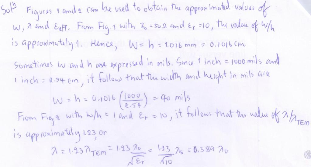
31 Characteristic impedance of the microstrip line versus w/h 31

32 Normalized wavelength of the microstrip line versus w/h 32
33 Ex8 A microstrip material with r = 10 and h = mm is used to build a TL. Determine the width for the microstrip TL to have a Z 0 = 50. Also determine the wavelength and the effective relative dielectric constant of the microstrip line. 33
34 34
35 35
36 Wavelength in the microstrip line Assume t/h 0.005, for w / h 0.6, for w / h 0.6, 0 r w r 10.6( r 1)( ) 0 r w r 10.63( r 1)( ) h h 1/ 2 1/ 2 36
37 37
38 Attenuation (losses in microstrip lines) conductor loss dielectric loss radiation loss tot c d where c = conductor attenuation (Np/m) d = dielectric attenuation (Np/m 38
39 Conductor attenuation R c c skin Rskin Zw o ( Np / m) Rskin ( db / m) Zw o 1 If the conductor is thin, then the more accurate skin resistance can be shown as 1 R skin t / (1 e ). 39
 r eff 2 ( 1) eff r tan Np / m")
40 Dielectric attenuation d 2 f c ( 1) r eff 2 ( 1) eff r tan Np / m 40
Transmission Lines. Plane wave propagating in air Y unguided wave propagation. Transmission lines / waveguides Y. guided wave propagation
 Transmission Lines Transmission lines and waveguides may be defined as devices used to guide energy from one point to another (from a source to a load). Transmission lines can consist of a set of conductors,
ANTENNAS and MICROWAVES ENGINEERING (650427)
") Philadelphia University Faculty of Engineering Communication and Electronics Engineering ANTENNAS and MICROWAVES ENGINEERING (65427) Part 2 Dr. Omar R Daoud 1 General Considerations It is a two-port network
Philadelphia University Faculty of Engineering Communication and Electronics Engineering ANTENNAS and MICROWAVES ENGINEERING (65427) Part 2 Dr. Omar R Daoud 1 General Considerations It is a two-port network
ECE 391 supplemental notes - #11. Adding a Lumped Series Element
 ECE 391 supplemental notes - #11 Adding a umped Series Element Consider the following T-line circuit: Z R,1! Z,2! Z z in,1 = r in,1 + jx in,1 Z in,1 = z in,1 Z,1 z = Z Z,2 zin,2 = r in,2 + jx in,2 z,1
Lecture 12 Date:
 Lecture 12 Date: 09.02.2017 Microstrip Matching Networks Series- and Shunt-stub Matching Quarter Wave Impedance Transformer Microstrip Line Matching Networks In the lower RF region, its often a standard
TRANSMISSION LINES AND MATCHING
 TRANSMISSION LINES AND MATCHING for High-Frequency Circuit Design Elective by Michael Tse September 2003 Contents Basic models The Telegrapher s equations and solutions Transmission line equations The
Solutions to Problems in Chapter 6
 Appendix F Solutions to Problems in Chapter 6 F.1 Problem 6.1 Short-circuited transmission lines Section 6.2.1 (book page 193) describes the method to determine the overall length of the transmission line
How to measure complex impedance at high frequencies where phase measurement is unreliable.
 Objectives In this course you will learn the following Various applications of transmission lines. How to measure complex impedance at high frequencies where phase measurement is unreliable. How and why
ECE357H1S ELECTROMAGNETIC FIELDS TERM TEST 1. 8 February 2016, 19:00 20:00. Examiner: Prof. Sean V. Hum
 UNIVERSITY OF TORONTO FACULTY OF APPLIED SCIENCE AND ENGINEERING The Edward S. Rogers Sr. Department of Electrical and Computer Engineering ECE57HS ELECTROMAGNETIC FIELDS TERM TEST 8 February 6, 9:00 :00
Microwave Circuit Design I
 9 1 Microwave Circuit Design I Lecture 9 Topics: 1. Admittance Smith Chart 2. Impedance Matching 3. Single-Stub Tuning Reading: Pozar pp. 228 235 The Admittance Smith Chart Since the following is also
y(d) = j
 = j") Problem 2.66 A 0-Ω transmission line is to be matched to a computer terminal with Z L = ( j25) Ω by inserting an appropriate reactance in parallel with the line. If f = 800 MHz and ε r = 4, determine the
Problem 2.66 A 0-Ω transmission line is to be matched to a computer terminal with Z L = ( j25) Ω by inserting an appropriate reactance in parallel with the line. If f = 800 MHz and ε r = 4, determine the
6-1 Chapter 6 Transmission Lines
 6-1 Chapter 6 Transmission ines ECE 3317 Dr. Stuart A. ong 6-2 General Definitions p.133 6-3 Voltage V( z) = α E ds ( C z) 1 C t t ( a) Current I( z) = α H ds ( C0 closed) 2 C 0 ( b) http://www.cartoonstock.com
Problem 1 Γ= = 0.1λ = max VSWR = 13
 Smith Chart Problems 1. The 0:1 length line shown has a characteristic impedance of 50 and is terminated with a load impedance of Z =5+j25. (a) ocate z = Z Z 0 =0:1+j0:5 onthe Smith chart. See the point
Impedance Matching. Generally, Z L = R L + jx L, X L 0. You need to turn two knobs to achieve match. Example z L = 0.5 j
 Impedance Matching Generally, Z L = R L + jx L, X L 0. You need to turn two knobs to achieve match. Example z L = 0.5 j This time, we do not want to cut the line to insert a matching network. Instead,
ECE 497 JS Lecture -07 Planar Transmission Lines
 ECE 497 JS Lecture -07 Planar Transmission Lines Spring 2004 Jose E. Schutt-Aine Electrical & Computer Engineering University of Illinois jose@emlab.uiuc.edu 1 Microstrip ε Z o w/h < 3.3 2 119.9 h h =
Lecture 9. The Smith Chart and Basic Impedance-Matching Concepts
 ecture 9 The Smith Chart and Basic Impedance-Matching Concepts The Smith Chart: Γ plot in the Complex Plane Smith s chart is a graphical representation in the complex Γ plane of the input impedance, the
Imaginary Impedance Axis. Real Impedance Axis. Smith Chart. The circles, tangent to the right side of the chart, are constant resistance circles
 The Smith Chart The Smith Chart is simply a graphical calculator for computing impedance as a function of reflection coefficient. Many problems can be easily visualized with the Smith Chart The Smith chart
ECE 451 Advanced Microwave Measurements. TL Characterization
 ECE 451 Advanced Microwave Measurements TL Characterization Jose E. Schutt-Aine Electrical & Computer Engineering University of Illinois jesa@illinois.edu ECE 451 Jose Schutt-Aine 1 Maxwell s Equations
5.2 Single-Stub Tuning
 3/26/29 5_2 Sgle_Stub Tung.doc 1/1 5.2 Sgle-Stub Tung Readg Assignment: pp. 228-235 Q: If we cannot use lumped elements like ductors or capacitors to build lossless matchg networks, what can we use? A:
Lecture 14 Date:
 Lecture 14 Date: 18.09.2014 L Type Matching Network Examples Nodal Quality Factor T- and Pi- Matching Networks Microstrip Matching Networks Series- and Shunt-stub Matching L Type Matching Network (contd.)
Berkeley. The Smith Chart. Prof. Ali M. Niknejad. U.C. Berkeley Copyright c 2017 by Ali M. Niknejad. September 14, 2017
 Berkeley The Smith Chart Prof. Ali M. Niknejad U.C. Berkeley Copyright c 17 by Ali M. Niknejad September 14, 17 1 / 29 The Smith Chart The Smith Chart is simply a graphical calculator for computing impedance
and Ee = E ; 0 they are separated by a dielectric material having u = io-s S/m, µ, = µ, 0
 602 CHAPTER 11 TRANSMISSION LINES 11.10 Two identical pulses each of magnitude 12 V and width 2 µs are incident at t = 0 on a lossless transmission line of length 400 m terminated with a load. If the two
Impedance Matching and Tuning
 C h a p t e r F i v e Impedance Matching and Tuning This chapter marks a turning point, in that we now begin to apply the theory and techniques of previous chapters to practical problems in microwave engineering.
) Rotate L by 120 clockwise to obtain in!! anywhere between load and generator: rotation by 2d in clockwise direction. d=distance from the load to the
 Rotate L by 120 clockwise to obtain in!! anywhere between load and generator: rotation by 2d in clockwise direction. d=distance from the load to the") 3.1 Smith Chart Construction: Start with polar representation of. L ; in on lossless lines related by simple phase change ) Idea: polar plot going from L to in involves simple rotation. in jj 1 ) circle
3.1 Smith Chart Construction: Start with polar representation of. L ; in on lossless lines related by simple phase change ) Idea: polar plot going from L to in involves simple rotation. in jj 1 ) circle
Transmission Line Basics II - Class 6
 Transmission Line Basics II - Class 6 Prerequisite Reading assignment: CH2 Acknowledgements: Intel Bus Boot Camp: Michael Leddige Agenda 2 The Transmission Line Concept Transmission line equivalent circuits
Kimmo Silvonen, Transmission lines, ver
 Kimmo Silvonen, Transmission lines, ver. 13.10.2008 1 1 Basic Theory The increasing operating and clock frequencies require transmission line theory to be considered more and more often! 1.1 Some practical
Electrodynamics and Microwaves 17. Stub Matching Technique in Transmission Lines
 1 Module 17 Stub Matching Technique in Transmission Lines 1. Introduction 2. Concept of matching stub 3. Mathematical Basis for Single shunt stub matching 4.Designing of single stub using Smith chart 5.
Case Study: Parallel Coupled- Line Combline Filter
 MICROWAVE AND RF DESIGN MICROWAVE AND RF DESIGN Case Study: Parallel Coupled- Line Combline Filter Presented by Michael Steer Reading: 6. 6.4 Index: CS_PCL_Filter Based on material in Microwave and RF
ECE 107: Electromagnetism
 ECE 107: Electromagnetism Set 2: Transmission lines Instructor: Prof. Vitaliy Lomakin Department of Electrical and Computer Engineering University of California, San Diego, CA 92093 1 Outline Transmission
Microwave Circuits Design
 The Smith Chart: The Smith chart is a graphical aide used to simplify the solution of Tx-line problems More importantly, the Smith chart allows us to visualize the periodic nature of the line impedance
PHY3128 / PHYM203 (Electronics / Instrumentation) Transmission Lines
 Transmission Lines") Transmission Lines Introduction A transmission line guides energy from one place to another. Optical fibres, waveguides, telephone lines and power cables are all electromagnetic transmission lines. are
Transmission Lines Introduction A transmission line guides energy from one place to another. Optical fibres, waveguides, telephone lines and power cables are all electromagnetic transmission lines. are
Lecture Outline 9/27/2017. EE 4347 Applied Electromagnetics. Topic 4a
 9/7/17 Course Instructor Dr. Raymond C. Rumpf Office: A 337 Phone: (915) 747 6958 E Mail: rcrumpf@utep.edu EE 4347 Applied Electromagnetics Topic 4a Transmission Lines Transmission These Lines notes may
Microwave Phase Shift Using Ferrite Filled Waveguide Below Cutoff
 Microwave Phase Shift Using Ferrite Filled Waveguide Below Cutoff CHARLES R. BOYD, JR. Microwave Applications Group, Santa Maria, California, U. S. A. ABSTRACT Unlike conventional waveguides, lossless
EELE 3332 Electromagnetic II Chapter 11. Transmission Lines. Islamic University of Gaza Electrical Engineering Department Dr.
 EEE 333 Electromagnetic II Chapter 11 Transmission ines Islamic University of Gaza Electrical Engineering Department Dr. Talal Skaik 1 1 11.1 Introduction Wave propagation in unbounded media is used in
2GHz Microstrip Low Pass Filter Design with Open-Circuited Stub
 IOSR Journal of Electronics and Communication Engineering (IOSR-JECE) e-issn: 2278-2834,p- ISSN: 2278-8735.Volume 13, Issue 2, Ver. II (Mar. - Apr. 2018), PP 01-09 www.iosrjournals.org 2GHz Microstrip
INTRODUCTION TO TRANSMISSION LINES DR. FARID FARAHMAND FALL 2012
 INTRODUCTION TO TRANSMISSION LINES DR. FARID FARAHMAND FALL 2012 http://www.empowermentresources.com/stop_cointelpro/electromagnetic_warfare.htm RF Design In RF circuits RF energy has to be transported
Microwave Network Analysis
 Prof. Dr. Mohammad Tariqul Islam titareq@gmail.my tariqul@ukm.edu.my Microwave Network Analysis 1 Text Book D.M. Pozar, Microwave engineering, 3 rd edition, 2005 by John-Wiley & Sons. Fawwaz T. ILABY,
High Speed Communication Circuits and Systems Lecture 4 Generalized Reflection Coefficient, Smith Chart, Integrated Passive Components
 High Speed Communication Circuits and Systems Lecture 4 Generalized Reflection Coefficient, Smith Chart, Integrated Passive Components Michael H. Perrott February 11, 2004 Copyright 2004 by Michael H.
ECE145A/218A Course Notes
 ECE145A/218A Course Notes Last note set: Introduction to transmission lines 1. Transmission lines are a linear system - superposition can be used 2. Wave equation permits forward and reverse wave propagation
Lecture 13 Date:
 ecture 3 Date: 6.09.204 The Signal Flow Graph (Contd.) Impedance Matching and Tuning Tpe Matching Network Example Signal Flow Graph (contd.) Splitting Rule Now consider the three equations SFG a a b 2
ECE 604, Lecture 13. October 16, 2018
 ECE 604, Lecture 13 October 16, 2018 1 Introduction In this lecture, we will cover the following topics: Terminated Transmission Line Smith Chart Voltage Standing Wave Ratio (VSWR) Additional Reading:
ECE 497 JS Lecture -03 Transmission Lines
 ECE 497 JS Lecture -03 Transmission Lines Spring 2004 Jose E. Schutt-Aine Electrical & Computer Engineering University of Illinois jose@emlab.uiuc.edu 1 MAXWELL S EQUATIONS B E = t Faraday s Law of Induction
Transmission Line Theory
 S. R. Zinka zinka@vit.ac.in School of Electronics Engineering Vellore Institute of Technology April 26, 2013 Outline 1 Free Space as a TX Line 2 TX Line Connected to a Load 3 Some Special Cases 4 Smith
TASK A. TRANSMISSION LINE AND DISCONTINUITIES
 TASK A. TRANSMISSION LINE AND DISCONTINUITIES Task A. Transmission Line and Discontinuities... 1 A.I. TEM Transmission Line... A.I.1. Circuit Representation of a Uniform Transmission Line... A.I.. Time
Module 2 : Transmission Lines. Lecture 10 : Transmisssion Line Calculations Using Smith Chart. Objectives. In this course you will learn the following
 Objectives In this course you will learn the following What is a constant VSWR circle on the - plane? Properties of constant VSWR circles. Calculations of load reflection coefficient. Calculation of reflection
ECE 598 JS Lecture 06 Multiconductors
 ECE 598 JS Lecture 06 Multiconductors Spring 2012 Jose E. Schutt-Aine Electrical & Computer Engineering University of Illinois jesa@illinois.edu 1 TELGRAPHER S EQUATION FOR N COUPLED TRANSMISSION LINES
Impedance matching via QWT
 Impedance matching via QWT Goal: Design a QWT matching network such that: Z in = Z 0 z in = 1 + j0 For ZL purely real: Z 0 Z T λ/4 Z L = r L + j0 Z in Since Z in Z L = Z 2 T a match is achieved with a
Introduction to RF Design. RF Electronics Spring, 2016 Robert R. Krchnavek Rowan University
 Introduction to RF Design RF Electronics Spring, 2016 Robert R. Krchnavek Rowan University Objectives Understand why RF design is different from lowfrequency design. Develop RF models of passive components.
Effects from the Thin Metallic Substrate Sandwiched in Planar Multilayer Microstrip Lines
 Progress In Electromagnetics Research Symposium 2006, Cambridge, USA, March 26-29 115 Effects from the Thin Metallic Substrate Sandwiched in Planar Multilayer Microstrip Lines L. Zhang and J. M. Song Iowa
Application of EM- Simulators for Extraction of Line Parameters
 Chapter - 2 Application of EM- Simulators for Extraction of Line Parameters 2. 1 Introduction The EM-simulators-2D, 2.5D and 3D, are powerful tools for the analysis of the planar transmission lines structure.
Contents. Transmission Lines The Smith Chart Vector Network Analyser (VNA) ü structure ü calibration ü operation. Measurements
 ü structure ü calibration ü operation. Measurements") Contents Transmission Lines The Smith Chart Vector Network Analyser (VNA) ü structure ü calibration ü operation Measurements Göran Jönsson, EIT 2015-04-27 Vector Network Analysis 2 Waves on Lines If the
Contents Transmission Lines The Smith Chart Vector Network Analyser (VNA) ü structure ü calibration ü operation Measurements Göran Jönsson, EIT 2015-04-27 Vector Network Analysis 2 Waves on Lines If the
Topic 5: Transmission Lines
 Topic 5: Transmission Lines Profs. Javier Ramos & Eduardo Morgado Academic year.13-.14 Concepts in this Chapter Mathematical Propagation Model for a guided transmission line Primary Parameters Secondary
Annexure-I. network acts as a buffer in matching the impedance of the plasma reactor to that of the RF
 Annexure-I Impedance matching and Smith chart The output impedance of the RF generator is 50 ohms. The impedance matching network acts as a buffer in matching the impedance of the plasma reactor to that
TECHNO INDIA BATANAGAR
 TECHNO INDIA BATANAGAR ( DEPARTMENT OF ELECTRONICS & COMMUNICATION ENGINEERING) QUESTION BANK- 2018 1.Vector Calculus Assistant Professor 9432183958.mukherjee@tib.edu.in 1. When the operator operates on
ECE 451 Transmission Lines & Packaging
 Transmission Lines & Packaging Jose E. Schutt-Aine Electrical & Computer Engineering University of Illinois jose@emlab.uiuc.edu 1 Radio Spectrum Bands The use of letters to designate bands has long ago
Transmission Line Basics
 Transmission Line Basics Prof. Tzong-Lin Wu NTUEE 1 Outlines Transmission Lines in Planar structure. Key Parameters for Transmission Lines. Transmission Line Equations. Analysis Approach for Z and T d
This section reviews the basic theory of accuracy enhancement for one-port networks.
 Vector measurements require both magnitude and phase data. Some typical examples are the complex reflection coefficient, the magnitude and phase of the transfer function, and the group delay. The seminar
Prepared by: Eng. Talal F. Skaik
 Islamic University of Gaza Faculty of Engineering Electrical & Computer Dept. Prepared by: Eng. Talal F. Skaik Microwaves Lab Experiment #3 Single Stub Matching Objectives: Understanding Impedance Matching,
Module 2 : Transmission Lines. Lecture 1 : Transmission Lines in Practice. Objectives. In this course you will learn the following
 Objectives In this course you will learn the following Point 1 Point 2 Point 3 Point 4 Point 5 Point 6 Point 7 Point 8 Point 9 Point 10 Point 11 Point 12 Various Types Of Transmission Line Explanation:
Waves on Lines. Contents. ! Transmission Lines! The Smith Chart! Vector Network Analyser (VNA) ! Measurements
 ! Measurements") Waves on Lines If the wavelength to be considered is significantly greater compared to the size of the circuit the voltage will be independent of the location. amplitude d! distance but this is not true
Waves on Lines If the wavelength to be considered is significantly greater compared to the size of the circuit the voltage will be independent of the location. amplitude d! distance but this is not true
ECE 6340 Fall Homework 2. Please do the following problems (you may do the others for practice if you wish): Probs. 1, 2, 3, 4, 5, 6, 7, 10, 12
: Probs. 1, 2, 3, 4, 5, 6, 7, 10, 12") ECE 634 Fall 16 Homework Please do the following problems (you may do the others for practice if you wish: Probs. 1,, 3, 4, 5, 6, 7, 1, 1 1 Consider two parallel infinite wires in free space each carrying
ECE 634 Fall 16 Homework Please do the following problems (you may do the others for practice if you wish: Probs. 1,, 3, 4, 5, 6, 7, 1, 1 1 Consider two parallel infinite wires in free space each carrying
Non-Sinusoidal Waves on (Mostly Lossless)Transmission Lines
Transmission Lines") Non-Sinusoidal Waves on (Mostly Lossless)Transmission Lines Don Estreich Salazar 21C Adjunct Professor Engineering Science October 212 https://www.iol.unh.edu/services/testing/sas/tools.php 1 Outline of
Non-Sinusoidal Waves on (Mostly Lossless)Transmission Lines Don Estreich Salazar 21C Adjunct Professor Engineering Science October 212 https://www.iol.unh.edu/services/testing/sas/tools.php 1 Outline of
Microwave Engineering 3e Author - D. Pozar
 Microwave Engineering 3e Author - D. Pozar Sections 3.6 3.8 Presented by Alex Higgins 1 Outline Section 3.6 Surface Waves on a Grounded Dielectric Slab Section 3.7 Stripline Section 3.8 Microstrip An Investigation
Electromagnetic-Thermal Analysis Study Based on HFSS-ANSYS Link
 Syracuse University SURFACE Electrical Engineering and Computer Science Technical Reports College of Engineering and Computer Science 5-9-2011 Electromagnetic-Thermal Analysis Study Based on HFSS-ANSYS
A Method to Extract Dielectric Parameters from Transmission Lines with Conductor Surface Roughness at Microwave Frequencies
 Progress In Electromagnetics Research M, Vol. 48, 1 8, 2016 A Method to Extract Dielectric Parameters from Transmission Lines with Conductor Surface Roughness at Microwave Frequencies Binke Huang * and
STUB BASED EQUIVALENT CIRCUIT MODELS FOR EVEN/ODD MODE DUAL CRLH UNIT CELLS. Faculty of Engineering, Ain Shams University, Cairo, Egypt
 Progress In Electromagnetics Research M, Vol. 3, 95 9, 3 STUB BASED EQUIVALENT CIRCUIT MODELS FOR EVEN/ODD MODE DUAL CRLH UNIT CELLS Amr M. E. Safwat, *, Amr A. Ibrahim, Mohamed A. Othman, Marwah Shafee,
Impedance Matching with Transmission Lines
 Impedance Matching with Transmission Lines /4 W Z L useful functions and identities Units Constants Table of Contents I. Introduction II. Inputs III. Transmission Line Synthesis Function IV. Single Shunt
Contents. Transmission Lines The Smith Chart Vector Network Analyser (VNA) ü structure ü calibration ü operation. Measurements
 ü structure ü calibration ü operation. Measurements") Contents Transmission Lines The Smith Chart Vector Network Analyser (VNA) ü structure ü calibration ü operation Measurements Göran Jönsson, EIT 2017-05-12 Vector Network Analysis 2 Waves on Lines If the
Contents Transmission Lines The Smith Chart Vector Network Analyser (VNA) ü structure ü calibration ü operation Measurements Göran Jönsson, EIT 2017-05-12 Vector Network Analysis 2 Waves on Lines If the
Introduction. A microwave circuit is an interconnection of components whose size is comparable with the wavelength at the operation frequency
 Introduction A microwave circuit is an interconnection of components whose size is comparable with the wavelength at the operation frequency Type of Components: Interconnection: it is not an ideal connection
November MVP R&S FSW Analyzer. Vol. 54 No. 11. Founded in mwjournal.com
 Vol. 54 No. 11 November 211 MVP R&S FSW Analyzer Founded in 1958 mwjournal.com Improved Thermal Management of Microwave PCBs Using Advanced Circuit Materials Thermal management in microwave printed-circuit
Characteristics of Passive IC Devices
 008/Oct 8 esistors Characteristics of Passive IC Devices Poly esistance Diffusion esistance Well esistance Parasitic esistance Capacitors Poly Capacitors MOS Capacitors MIM Capacitors Parasitic Capacitors
Contents. ! Transmission Lines! The Smith Chart! Vector Network Analyser (VNA) ! Measurements. ! structure! calibration! operation
 ! Measurements. ! structure! calibration! operation") Contents! Transmission Lines! The Smith Chart! Vector Network Analyser (VNA)! structure! calibration! operation! Measurements Göran Jönsson, EIT 2009-11-16 Network Analysis 2! Waves on Lines! If the wavelength
Contents! Transmission Lines! The Smith Chart! Vector Network Analyser (VNA)! structure! calibration! operation! Measurements Göran Jönsson, EIT 2009-11-16 Network Analysis 2! Waves on Lines! If the wavelength
ECE357H1F ELECTROMAGNETIC FIELDS FINAL EXAM. 28 April Examiner: Prof. Sean V. Hum. Duration: hours
 UNIVERSITY OF TORONTO FACULTY OF APPLIED SCIENCE AND ENGINEERING The Edward S. Rogers Sr. Department of Electrical and Computer Engineering ECE357H1F ELECTROMAGNETIC FIELDS FINAL EXAM 28 April 15 Examiner:
1 Chapter 8 Maxwell s Equations
 Electromagnetic Waves ECEN 3410 Prof. Wagner Final Review Questions 1 Chapter 8 Maxwell s Equations 1. Describe the integral form of charge conservation within a volume V through a surface S, and give
Introduction to Network Analysis of Microwave Circuits
 1 Introduction to Network Analysis of Microwave Circuits ABSTRACT Network presentation has been used as a technique in the analysis of lowfrequency electrical electronic circuits. The same technique is
INSTITUTE OF AERONAUTICAL ENGINEERING Dundigal, Hyderabad Electronics and Communicaton Engineering
 INSTITUTE OF AERONAUTICAL ENGINEERING Dundigal, Hyderabad - 00 04 Electronics and Communicaton Engineering Question Bank Course Name : Electromagnetic Theory and Transmission Lines (EMTL) Course Code :
192 Chapter 4: Microwave Network Analysis
 92 hapter 4: Microwave Network nalysis TLE 4.2 onversions etween Two-Port Network Parameters S Z Y S S (Z Z 0 )(2 + Z 0 ) (Y 0 Y )(Y 0 + Y 22 ) + Y 2 Y 2 + /Z 0 Z 0 + /Z 0 + Z 0 + S S 2Z 2 Z 0 2 2 2Y 2
Transmission and Distribution of Electrical Power
 KINGDOM OF SAUDI ARABIA Ministry Of High Education Umm Al-Qura University College of Engineering & Islamic Architecture Department Of Electrical Engineering Transmission and Distribution of Electrical
EE Lecture 7. Finding gamma. Alternate form. I i. Transmission line. Z g I L Z L. V i. V g - Z in Z. z = -l z = 0
 Impedance on lossless lines EE - Lecture 7 Impedance on lossless lines Reflection coefficient Impedance equation Shorted line example Assigned reading: Sec.. of Ulaby For lossless lines, γ = jω L C = jβ;
Lecture 17 Date:
 Lecture 17 Date: 09.03.017 The Quadrature Hybrid We began our discussion of dividers and couplers by considering important general properties of three- and four-port networks. This was followed by an analysis
Lecture 2 - Transmission Line Theory
 Lecture 2 - Transmission Line Theory Microwave Active Circuit Analysis and Design Clive Poole and Izzat Darwazeh Academic Press Inc. Poole-Darwazeh 2015 Lecture 2 - Transmission Line Theory Slide1 of 54
Design of all-pole microwave filters. Giuseppe Macchiarella Polytechnic of Milan, Italy Electronic and Information Department
 Design of all-pole microwave filters Giuseppe Macchiarella Polytechnic of Milan, Italy Electronic and Information Department In-line filters with all-equal resonators R L eq, f L eq, f L eq, f L eq, f
Contents. Notes based on Fundamentals of Applied Electromagnetics (Ulaby et al) for ECE331, PSU.
 for ECE331, PSU.") 1 Contents 2 Transmission lines 3 2.1 Transmission Lines: General Considerations...... 3 2.1.1 Wavelength and transmission lines....... 4 2.1.2 Propagation modes................ 8 2.2 Lumped element model.................
1 Contents 2 Transmission lines 3 2.1 Transmission Lines: General Considerations...... 3 2.1.1 Wavelength and transmission lines....... 4 2.1.2 Propagation modes................ 8 2.2 Lumped element model.................
Broadband transmission line models for analysis of serial data channel interconnects
 PCB Design Conference East, Durham NC, October 23, 2007 Broadband transmission line models for analysis of serial data channel interconnects Y. O. Shlepnev, Simberian, Inc. shlepnev@simberian.com Simberian:
Electromagnetic Waves
 Electromagnetic Waves Maxwell s equations predict the propagation of electromagnetic energy away from time-varying sources (current and charge) in the form of waves. Consider a linear, homogeneous, isotropic
6.976 High Speed Communication Circuits and Systems Lecture 2 Transmission Lines
 6.976 High Speed Communication Circuits and Sstems Lecture 2 Transmission Lines Michael Perrott Massachusetts Institute of Technolog Copright 2003 b Michael H. Perrott Mawell s Equations General form:
Lecture 19 Date:
 Lecture 19 Date: 8.10.014 The Quadrature Hybrid We began our discussion of dividers and couplers by considering important general properties of three- and fourport networks. This was followed by an analysis
COMPACT BANDSTOP FILTER WITH MULTIPLE RE- JECTION ZEROS. Electronic Science and Technology of China, Chengdu , China
 Progress In Electromagnetics Research Letters, Vol. 37, 55 64, 2013 COMPACT BANDSTOP FILTER WITH MULTIPLE RE- JECTION ZEROS Guotao Yue 1, *, Xubo Wei 1, 2, Bo Fu 1, Shuanglin Yuan 1, Meijuan Xu 1, and
ECE 546 Lecture 13 Scattering Parameters
 ECE 546 Lecture 3 Scattering Parameters Spring 08 Jose E. Schutt-Aine Electrical & Computer Engineering University of Illinois jesa@illinois.edu ECE 546 Jose Schutt Aine Transfer Function Representation
AC Circuits Homework Set
 Problem 1. In an oscillating LC circuit in which C=4.0 μf, the maximum potential difference across the capacitor during the oscillations is 1.50 V and the maximum current through the inductor is 50.0 ma.
ELECTROMAGNETIC FIELDS AND WAVES
 ELECTROMAGNETIC FIELDS AND WAVES MAGDY F. ISKANDER Professor of Electrical Engineering University of Utah Englewood Cliffs, New Jersey 07632 CONTENTS PREFACE VECTOR ANALYSIS AND MAXWELL'S EQUATIONS IN
Transmission line equations in phasor form
 Transmission line equations in phasor form Kenneth H. Carpenter Department of Electrical and Computer Engineering Kansas State University November 19, 2004 The text for this class presents transmission
Voltage reflection coefficient Γ. L e V V. = e. At the load Γ (l = 0) ; Γ = V V
 ; Γ = V V") of 3 Smith hart Tutorial Part To begin with we start with the definition of SWR, which is the ratio of the reflected voltage over the incident voltage. The Reflection coefficient Γ is simply the complex
of 3 Smith hart Tutorial Part To begin with we start with the definition of SWR, which is the ratio of the reflected voltage over the incident voltage. The Reflection coefficient Γ is simply the complex
A Note on the Modeling of Transmission-Line Losses
 Appears in IEEE Transactions on Microwave Theory & Technology, vol. 51, pp. 483-486, February 2003. A Note on the Modeling of Transmission-Line Losses Antonije R. Djordjević, Alenka G. Zajić, Dejan V.
Lowpass L Matching Network Designer
 Lowpass L Matching Network Designer V S L V L I S j*x S C j*x L Table of Contents I. General Impedance Matching II. Impedance Transformation for Power Amplifiers III. Inputs IV. Calculations V. Outputs
JCP Software & Company, Inc
 lide-rule TM for Microsoft Windows Microwave Transistor Amplifier Design Introduction and Reference Manual unstable. unstable L. VWR(out) db NF OPT L.4 db..8 db.6 db.. Ga 8 db Ga 7 db Ga 6 db. JCP oftware
Plane Waves GATE Problems (Part I)
") Plane Waves GATE Problems (Part I). A plane electromagnetic wave traveling along the + z direction, has its electric field given by E x = cos(ωt) and E y = cos(ω + 90 0 ) the wave is (a) linearly polarized
Plane Waves GATE Problems (Part I). A plane electromagnetic wave traveling along the + z direction, has its electric field given by E x = cos(ωt) and E y = cos(ω + 90 0 ) the wave is (a) linearly polarized
An Introduction to the Smith Chart for Amateur Radio. Jesse Sheinwald, N2CA
 An Introduction to the Smith Chart for Amateur Radio Jesse Sheinwald, N2CA jsheinwald@pobox.com ± 180 50 20 0.1 0.3 0.5 0.7 0.9 1.2 1.4 1.6 1.8 2.0 3.0 4.0 5.0 10 20 50-90 0 0 < 0.1 0.3 0.5 0.7 0.9 1.2
Lipparini* anazysis which compare favourabzy with experimentaz results. The same modez. described. It is shown that the discrepancies between computed
 ACCURATE ANALYSIS AND DESIGN OF MICROSTRIP INTERDIGITATED COUPLERS Vittorio Rizzoli*- Alessandro Lipparini* Abstract. The ezectricaz behaviour of interdigitated directionaz coupzers in an inhomogeneous
The Wire EE141. Microelettronica
 The Wire 1 Interconnect Impact on Chip 2 Example: a Bus Network transmitters receivers schematics physical 3 Wire Models All-inclusive model Capacitance-only 4 Impact of Interconnect Parasitics Interconnect
Engineering Electromagnetics
 Nathan Ida Engineering Electromagnetics With 821 Illustrations Springer Contents Preface vu Vector Algebra 1 1.1 Introduction 1 1.2 Scalars and Vectors 2 1.3 Products of Vectors 13 1.4 Definition of Fields