y(d) = j
|
|
|
- Aldous Augustine Summers
- 5 years ago
- Views:
Transcription
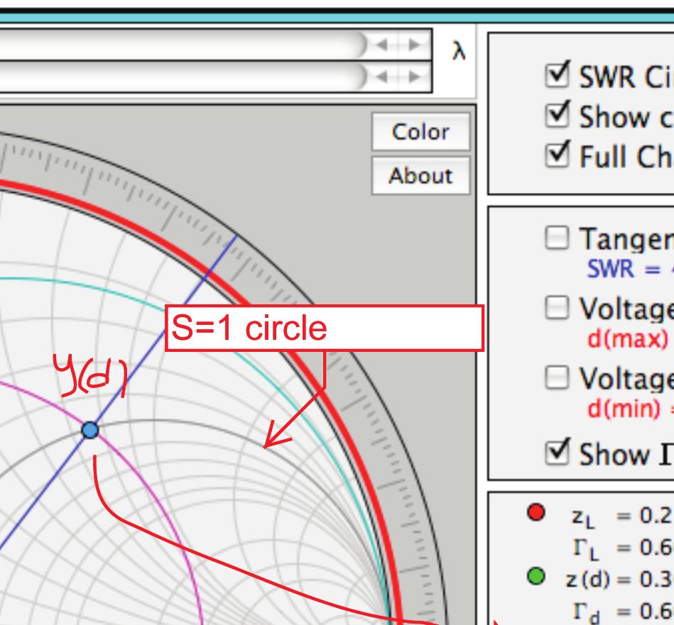
1 Problem 2.66 A 0-Ω transmission line is to be matched to a computer terminal with Z L = ( j25) Ω by inserting an appropriate reactance in parallel with the line. If f = 800 MHz and ε r = 4, determine the location nearest to the load at which inserting: (a) A capacitor can achieve the required matching, and the value of the capacitor. (b) An inductor can achieve the required matching, and the value of the inductor. Solution: (a) After entering the specified values for Z L and Z 0 into Module 2.6, we have z L represented by the red dot in Fig. P2.66(a), and y L represented by the blue dot. By moving the cursor a distance d = 0.093λ, the blue dot arrives at the intersection point between the SWR circle and the S = 1 circle. At that point y(d) = j To cancel the imaginary part, we need to add a reactive element whose admittance is positive, such as a capacitor. That is: ωc = (1.546) Y 0 = = = , Z 0 0 which leads to C = π 8 8 = F.
 (b) Repeating the")

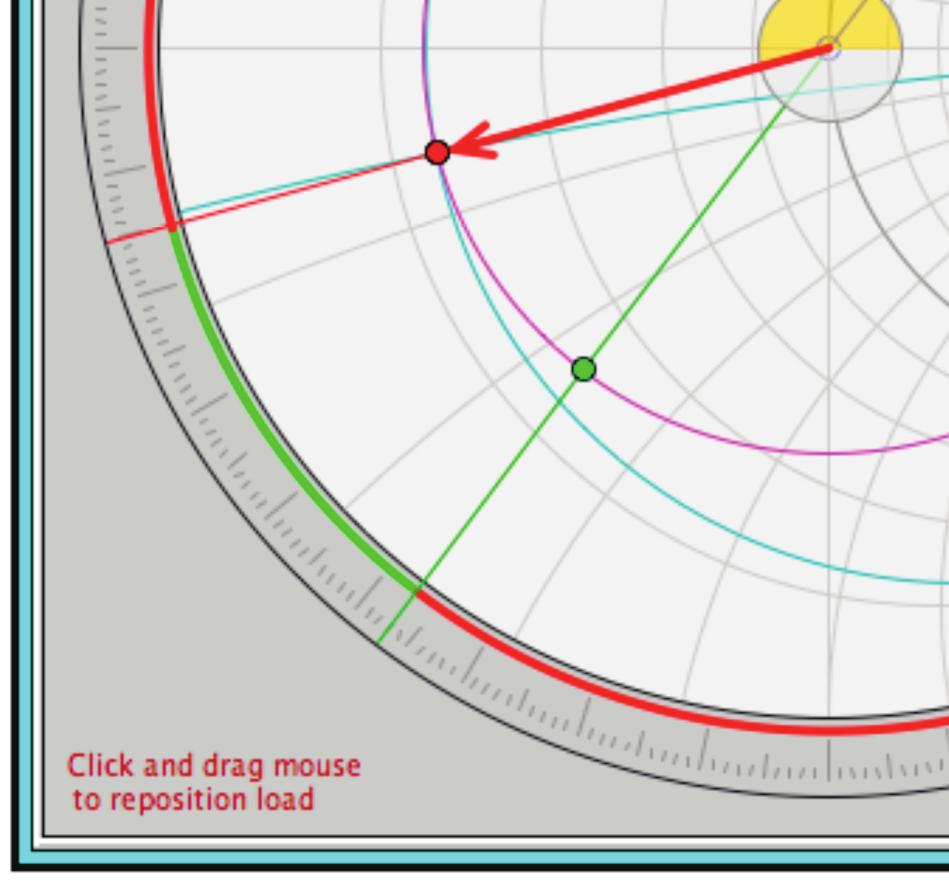
![66(b)] leads to y(d) = 00001](/docs-images/90/101412075/images/2-3.jpg "+ j1.5691, at d2 = 47806λ.")


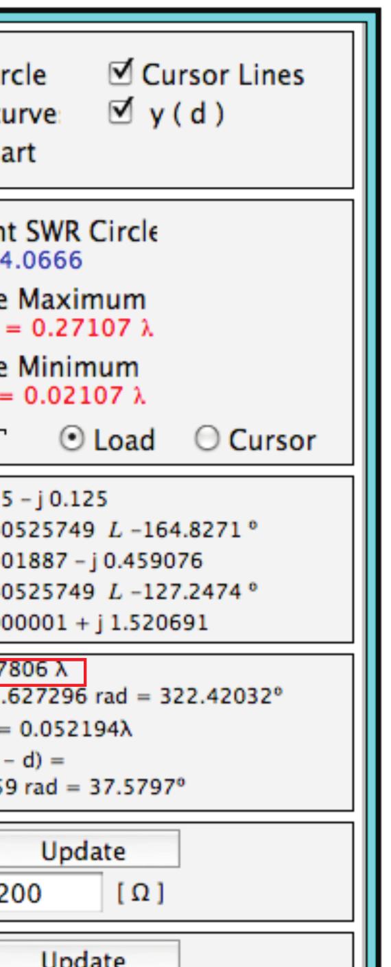
2 Figure P2.66(a) (b) Repeating the procedure for the second intersection point [Fig. P2.66(b)] leads to y(d) = j1.5691, at d2 = 47806λ. To cancel the imaginary part, we add an inductor in parallel such that =, ωl 0 from which we obtain L= 0 = H π 8 8
")
3 Figure P2.66(b)
4 Problem 2.68 A -Ω lossless line is to be matched to an antenna with Z L = (75 j) Ω using a shorted stub. Use the Smith chart to determine the stub length and distance between the antenna and stub ± > WAVELENGTHS TOWARD GENERATOR > < WAVELENGTHS TOWARD LOAD < λ INDUCTIVE REACTANCE COMPONENT (+jx/zo), OR CAPACITIVE SUSCEPTANCE (+jb/yo) RESISTANCE COMPONENT (R/Zo), OR CONDUCTANCE COMPONENT (G/Yo) CAPACITIVE REACTANCE COMPONENT (-jx/zo), OR INDUCTIVE SUSCEPTANCE (-jb/yo) Y-STUB-IN Y-LOAD Y-LOAD-IN Z-LOAD λ ANGLE OF REFLECTION COEFFICIENT IN DEGREES Y-SHT Figure P2.68: (a) First solution to Problem Solution: Refer to Fig. P2.68(a) and Fig. P2.68(b), which represent two different solutions. z L = Z L (75 j) Ω = = 1.5 j Z 0 Ω and is located at point Z-LOAD in both figures. Since it is advantageous to work in admittance coordinates, y L is plotted as point Y -LOAD in both figures. Y -LOAD is at 0.041λ on the WTG scale.
5 For the first solution in Fig. P2.68(a), point Y -LOAD-IN-1 represents the point at which g = 1 on the SWR circle of the load. Y -LOAD-IN-1 is at 45λ on the WTG scale, so the stub should be located at 45λ 0.041λ = 04λ from the load (or some multiple of a half wavelength further). At Y -LOAD-IN-1, b = 2, so a stub with an input admittance of y stub = 0 j2 is required. This point is Y -STUB-IN-1 and is at 23λ on the WTG scale. The short circuit admittance is denoted by point Y -SHT, located at λ. Therefore, the short stub must be 23λ λ = 73λ long (or some multiple of a half wavelength longer) ± > WAVELENGTHS TOWARD GENERATOR > < WAVELENGTHS TOWARD LOAD < Y-STUB-IN-2 INDUCTIVE REACTANCE COMPONENT (+jx/zo), OR CAPACITIVE SUSCEPTANCE (+jb/yo) RESISTANCE COMPONENT (R/Zo), OR CONDUCTANCE COMPONENT (G/Yo) CAPACITIVE REACTANCE COMPONENT (-jx/zo), OR INDUCTIVE SUSCEPTANCE (-jb/yo) 27 λ Y-LOAD Z-LOAD Y-LOAD-IN λ ANGLE OF REFLECTION COEFFICIENT IN DEGREES Y-SHT Figure P2.68: (b) Second solution to Problem For the second solution in Fig. P2.68(b), point Y -LOAD-IN-2 represents the point at which g = 1 on the SWR circle of the load. Y -LOAD-IN-2 is at 55λ on the WTG scale, so the stub should be located at 55λ 0.041λ = 14λ from the
6 load (or some multiple of a half wavelength further). At Y -LOAD-IN-2, b = 2, so a stub with an input admittance of y stub = 0 + j2 is required. This point is Y -STUB-IN-2 and is at 0.077λ on the WTG scale. The short circuit admittance is denoted by point Y -SHT, located at λ. Therefore, the short stub must be 0.077λ λ + 0.0λ = 27λ long (or some multiple of a half wavelength longer).
7 Problem 3.12 Two lines in the x y plane are described by the expressions: Line 1 x+2y = 6, Line 2 3x+4y = 8. Use vector algebra to find the smaller angle between the lines at their intersection point (0, 2) (0, -3) A B (, -13) θ AB Figure P3.12: Lines 1 and 2. Solution: Intersection point is found by solving the two equations simultaneously: 2x 4y = 12, 3x+4y = 8. The sum gives x =, which, when used in the first equation, gives y = 13. Hence, intersection point is (, 13). Another point on line 1 is x = 0, y = 3. Vector A from (0, 3) to (, 13) is A = ˆx()+ŷ( 13+3) = ˆx ŷ, A = = 0. A point on line 2 is x = 0, y = 2. Vector B from (0,2) to (, 13) is B = ˆx()+ŷ( 13 2) = ˆx ŷ15,
8 B = = 625. Angle between A and B is ( ) ( ) A B θ AB = cos 1 = cos 1 = 1. A B 0 625
Berkeley. The Smith Chart. Prof. Ali M. Niknejad. U.C. Berkeley Copyright c 2017 by Ali M. Niknejad. September 14, 2017
 Berkeley The Smith Chart Prof. Ali M. Niknejad U.C. Berkeley Copyright c 17 by Ali M. Niknejad September 14, 17 1 / 29 The Smith Chart The Smith Chart is simply a graphical calculator for computing impedance
Microwave Circuits Design
 The Smith Chart: The Smith chart is a graphical aide used to simplify the solution of Tx-line problems More importantly, the Smith chart allows us to visualize the periodic nature of the line impedance
ECE357H1S ELECTROMAGNETIC FIELDS TERM TEST 1. 8 February 2016, 19:00 20:00. Examiner: Prof. Sean V. Hum
 UNIVERSITY OF TORONTO FACULTY OF APPLIED SCIENCE AND ENGINEERING The Edward S. Rogers Sr. Department of Electrical and Computer Engineering ECE57HS ELECTROMAGNETIC FIELDS TERM TEST 8 February 6, 9:00 :00
Impedance Matching. Generally, Z L = R L + jx L, X L 0. You need to turn two knobs to achieve match. Example z L = 0.5 j
 Impedance Matching Generally, Z L = R L + jx L, X L 0. You need to turn two knobs to achieve match. Example z L = 0.5 j This time, we do not want to cut the line to insert a matching network. Instead,
Impedance Matching and Tuning
 C h a p t e r F i v e Impedance Matching and Tuning This chapter marks a turning point, in that we now begin to apply the theory and techniques of previous chapters to practical problems in microwave engineering.
ECE 391 supplemental notes - #11. Adding a Lumped Series Element
 ECE 391 supplemental notes - #11 Adding a umped Series Element Consider the following T-line circuit: Z R,1! Z,2! Z z in,1 = r in,1 + jx in,1 Z in,1 = z in,1 Z,1 z = Z Z,2 zin,2 = r in,2 + jx in,2 z,1
Imaginary Impedance Axis. Real Impedance Axis. Smith Chart. The circles, tangent to the right side of the chart, are constant resistance circles
 The Smith Chart The Smith Chart is simply a graphical calculator for computing impedance as a function of reflection coefficient. Many problems can be easily visualized with the Smith Chart The Smith chart
How to measure complex impedance at high frequencies where phase measurement is unreliable.
 Objectives In this course you will learn the following Various applications of transmission lines. How to measure complex impedance at high frequencies where phase measurement is unreliable. How and why
Lecture 14 Date:
 Lecture 14 Date: 18.09.2014 L Type Matching Network Examples Nodal Quality Factor T- and Pi- Matching Networks Microstrip Matching Networks Series- and Shunt-stub Matching L Type Matching Network (contd.)
An Introduction to the Smith Chart for Amateur Radio. Jesse Sheinwald, N2CA
 An Introduction to the Smith Chart for Amateur Radio Jesse Sheinwald, N2CA jsheinwald@pobox.com ± 180 50 20 0.1 0.3 0.5 0.7 0.9 1.2 1.4 1.6 1.8 2.0 3.0 4.0 5.0 10 20 50-90 0 0 < 0.1 0.3 0.5 0.7 0.9 1.2
TC 412 Microwave Communications. Lecture 6 Transmission lines problems and microstrip lines
 TC 412 Microwave Communications Lecture 6 Transmission lines problems and microstrip lines RS 1 Review Input impedance for finite length line Quarter wavelength line Half wavelength line Smith chart A
Problem 1 Γ= = 0.1λ = max VSWR = 13
 Smith Chart Problems 1. The 0:1 length line shown has a characteristic impedance of 50 and is terminated with a load impedance of Z =5+j25. (a) ocate z = Z Z 0 =0:1+j0:5 onthe Smith chart. See the point
Lecture 12 Date:
 Lecture 12 Date: 09.02.2017 Microstrip Matching Networks Series- and Shunt-stub Matching Quarter Wave Impedance Transformer Microstrip Line Matching Networks In the lower RF region, its often a standard
Transmission Lines. Plane wave propagating in air Y unguided wave propagation. Transmission lines / waveguides Y. guided wave propagation
 Transmission Lines Transmission lines and waveguides may be defined as devices used to guide energy from one point to another (from a source to a load). Transmission lines can consist of a set of conductors,
ANTENNAS and MICROWAVES ENGINEERING (650427)
") Philadelphia University Faculty of Engineering Communication and Electronics Engineering ANTENNAS and MICROWAVES ENGINEERING (65427) Part 2 Dr. Omar R Daoud 1 General Considerations It is a two-port network
Philadelphia University Faculty of Engineering Communication and Electronics Engineering ANTENNAS and MICROWAVES ENGINEERING (65427) Part 2 Dr. Omar R Daoud 1 General Considerations It is a two-port network
TRANSMISSION LINES AND MATCHING
 TRANSMISSION LINES AND MATCHING for High-Frequency Circuit Design Elective by Michael Tse September 2003 Contents Basic models The Telegrapher s equations and solutions Transmission line equations The
Annexure-I. network acts as a buffer in matching the impedance of the plasma reactor to that of the RF
 Annexure-I Impedance matching and Smith chart The output impedance of the RF generator is 50 ohms. The impedance matching network acts as a buffer in matching the impedance of the plasma reactor to that
Sinusoidal Steady State Analysis (AC Analysis) Part I
 Part I") Sinusoidal Steady State Analysis (AC Analysis) Part I Amin Electronics and Electrical Communications Engineering Department (EECE) Cairo University elc.n102.eng@gmail.com http://scholar.cu.edu.eg/refky/
Sinusoidal Steady State Analysis (AC Analysis) Part I Amin Electronics and Electrical Communications Engineering Department (EECE) Cairo University elc.n102.eng@gmail.com http://scholar.cu.edu.eg/refky/
) Rotate L by 120 clockwise to obtain in!! anywhere between load and generator: rotation by 2d in clockwise direction. d=distance from the load to the
 Rotate L by 120 clockwise to obtain in!! anywhere between load and generator: rotation by 2d in clockwise direction. d=distance from the load to the") 3.1 Smith Chart Construction: Start with polar representation of. L ; in on lossless lines related by simple phase change ) Idea: polar plot going from L to in involves simple rotation. in jj 1 ) circle
3.1 Smith Chart Construction: Start with polar representation of. L ; in on lossless lines related by simple phase change ) Idea: polar plot going from L to in involves simple rotation. in jj 1 ) circle
AC Circuits Homework Set
 Problem 1. In an oscillating LC circuit in which C=4.0 μf, the maximum potential difference across the capacitor during the oscillations is 1.50 V and the maximum current through the inductor is 50.0 ma.
ECE357H1F ELECTROMAGNETIC FIELDS FINAL EXAM. 28 April Examiner: Prof. Sean V. Hum. Duration: hours
 UNIVERSITY OF TORONTO FACULTY OF APPLIED SCIENCE AND ENGINEERING The Edward S. Rogers Sr. Department of Electrical and Computer Engineering ECE357H1F ELECTROMAGNETIC FIELDS FINAL EXAM 28 April 15 Examiner:
Chapter 1: Introduction: Waves and Phasors
 Chapter : Introduction: Waves and Phasors Lesson # Chapter Section: Chapter Topics: EM history and how it relates to other fields Highlights: EM in Classical era: 000 BC to 900 Examples of Modern Era Technology
Single Phase Parallel AC Circuits
 Single Phase Parallel AC Circuits 1 Single Phase Parallel A.C. Circuits (Much of this material has come from Electrical & Electronic Principles & Technology by John Bird) n parallel a.c. circuits similar
Solutions to Problems in Chapter 6
 Appendix F Solutions to Problems in Chapter 6 F.1 Problem 6.1 Short-circuited transmission lines Section 6.2.1 (book page 193) describes the method to determine the overall length of the transmission line
Lecture 9. The Smith Chart and Basic Impedance-Matching Concepts
 ecture 9 The Smith Chart and Basic Impedance-Matching Concepts The Smith Chart: Γ plot in the Complex Plane Smith s chart is a graphical representation in the complex Γ plane of the input impedance, the
mywbut.com Lesson 16 Solution of Current in AC Parallel and Seriesparallel
 esson 6 Solution of urrent in Parallel and Seriesparallel ircuits n the last lesson, the following points were described:. How to compute the total impedance/admittance in series/parallel circuits?. How
EE Lecture 7. Finding gamma. Alternate form. I i. Transmission line. Z g I L Z L. V i. V g - Z in Z. z = -l z = 0
 Impedance on lossless lines EE - Lecture 7 Impedance on lossless lines Reflection coefficient Impedance equation Shorted line example Assigned reading: Sec.. of Ulaby For lossless lines, γ = jω L C = jβ;
Module 4. Single-phase AC circuits. Version 2 EE IIT, Kharagpur
 Module 4 Single-phase circuits ersion EE T, Kharagpur esson 6 Solution of urrent in Parallel and Seriesparallel ircuits ersion EE T, Kharagpur n the last lesson, the following points were described:. How
Voltage reflection coefficient Γ. L e V V. = e. At the load Γ (l = 0) ; Γ = V V
 ; Γ = V V") of 3 Smith hart Tutorial Part To begin with we start with the definition of SWR, which is the ratio of the reflected voltage over the incident voltage. The Reflection coefficient Γ is simply the complex
of 3 Smith hart Tutorial Part To begin with we start with the definition of SWR, which is the ratio of the reflected voltage over the incident voltage. The Reflection coefficient Γ is simply the complex
Electrodynamics and Microwaves 17. Stub Matching Technique in Transmission Lines
 1 Module 17 Stub Matching Technique in Transmission Lines 1. Introduction 2. Concept of matching stub 3. Mathematical Basis for Single shunt stub matching 4.Designing of single stub using Smith chart 5.
Instructor s Guide Fundamentals of Applied Electromagnetics 2006 Media Edition Fawwaz T. Ulaby
 Instructor s Guide Fundamentals of Applied Electromagnetics 006 Media Edition Fawwaz T. Ulaby Dear Instructor: This Instructor s Guide is intended for use by the course instructor only. It was developed
Lecture 13 Date:
 ecture 3 Date: 6.09.204 The Signal Flow Graph (Contd.) Impedance Matching and Tuning Tpe Matching Network Example Signal Flow Graph (contd.) Splitting Rule Now consider the three equations SFG a a b 2
Microwave Circuit Design I
 9 1 Microwave Circuit Design I Lecture 9 Topics: 1. Admittance Smith Chart 2. Impedance Matching 3. Single-Stub Tuning Reading: Pozar pp. 228 235 The Admittance Smith Chart Since the following is also
MODULE-4 RESONANCE CIRCUITS
 Introduction: MODULE-4 RESONANCE CIRCUITS Resonance is a condition in an RLC circuit in which the capacitive and inductive Reactance s are equal in magnitude, there by resulting in purely resistive impedance.
Unit 21 Capacitance in AC Circuits
 Unit 21 Capacitance in AC Circuits Objectives: Explain why current appears to flow through a capacitor in an AC circuit. Discuss capacitive reactance. Discuss the relationship of voltage and current in
Contents. ! Transmission Lines! The Smith Chart! Vector Network Analyser (VNA) ! Measurements. ! structure! calibration! operation
 ! Measurements. ! structure! calibration! operation") Contents! Transmission Lines! The Smith Chart! Vector Network Analyser (VNA)! structure! calibration! operation! Measurements Göran Jönsson, EIT 2009-11-16 Network Analysis 2! Waves on Lines! If the wavelength
Contents! Transmission Lines! The Smith Chart! Vector Network Analyser (VNA)! structure! calibration! operation! Measurements Göran Jönsson, EIT 2009-11-16 Network Analysis 2! Waves on Lines! If the wavelength
EE221 Circuits II. Chapter 14 Frequency Response
 EE22 Circuits II Chapter 4 Frequency Response Frequency Response Chapter 4 4. Introduction 4.2 Transfer Function 4.3 Bode Plots 4.4 Series Resonance 4.5 Parallel Resonance 4.6 Passive Filters 4.7 Active
AC Circuit Analysis and Measurement Lab Assignment 8
 Electric Circuit Lab Assignments elcirc_lab87.fm - 1 AC Circuit Analysis and Measurement Lab Assignment 8 Introduction When analyzing an electric circuit that contains reactive components, inductors and
Sinusoidal Steady-State Analysis
 Sinusoidal Steady-State Analysis Mauro Forti October 27, 2018 Constitutive Relations in the Frequency Domain Consider a network with independent voltage and current sources at the same angular frequency
EE221 Circuits II. Chapter 14 Frequency Response
 EE22 Circuits II Chapter 4 Frequency Response Frequency Response Chapter 4 4. Introduction 4.2 Transfer Function 4.3 Bode Plots 4.4 Series Resonance 4.5 Parallel Resonance 4.6 Passive Filters 4.7 Active
Prepared by: Eng. Talal F. Skaik
 Islamic University of Gaza Faculty of Engineering Electrical & Computer Dept. Prepared by: Eng. Talal F. Skaik Microwaves Lab Experiment #3 Single Stub Matching Objectives: Understanding Impedance Matching,
ECE145A/218A Course Notes
 ECE145A/218A Course Notes Last note set: Introduction to transmission lines 1. Transmission lines are a linear system - superposition can be used 2. Wave equation permits forward and reverse wave propagation
6-1 Chapter 6 Transmission Lines
 6-1 Chapter 6 Transmission ines ECE 3317 Dr. Stuart A. ong 6-2 General Definitions p.133 6-3 Voltage V( z) = α E ds ( C z) 1 C t t ( a) Current I( z) = α H ds ( C0 closed) 2 C 0 ( b) http://www.cartoonstock.com
LCR Series Circuits. AC Theory. Introduction to LCR Series Circuits. Module. What you'll learn in Module 9. Module 9 Introduction
 Module 9 AC Theory LCR Series Circuits Introduction to LCR Series Circuits What you'll learn in Module 9. Module 9 Introduction Introduction to LCR Series Circuits. Section 9.1 LCR Series Circuits. Amazing
FINAL EXAM IN FYS-3007
 Page 1 of 4 pages + chart FINAL EXAM IN FYS-007 Exam in : Fys-007 Microwave Techniques Date : Tuesday, May 1, 2011 Time : 09.00 1.00 Place : Åsgårdveien 9 Approved remedies : All non-living and non-communicating
Module 2 : Transmission Lines. Lecture 10 : Transmisssion Line Calculations Using Smith Chart. Objectives. In this course you will learn the following
 Objectives In this course you will learn the following What is a constant VSWR circle on the - plane? Properties of constant VSWR circles. Calculations of load reflection coefficient. Calculation of reflection
Announcements: Today: more AC circuits
 Announcements: Today: more AC circuits I 0 I rms Current through a light bulb I 0 I rms I t = I 0 cos ωt I 0 Current through a LED I t = I 0 cos ωt Θ(cos ωt ) Theta function (is zero for a negative argument)
Impedance matching via QWT
 Impedance matching via QWT Goal: Design a QWT matching network such that: Z in = Z 0 z in = 1 + j0 For ZL purely real: Z 0 Z T λ/4 Z L = r L + j0 Z in Since Z in Z L = Z 2 T a match is achieved with a
Contents. Transmission Lines The Smith Chart Vector Network Analyser (VNA) ü structure ü calibration ü operation. Measurements
 ü structure ü calibration ü operation. Measurements") Contents Transmission Lines The Smith Chart Vector Network Analyser (VNA) ü structure ü calibration ü operation Measurements Göran Jönsson, EIT 2015-04-27 Vector Network Analysis 2 Waves on Lines If the
Contents Transmission Lines The Smith Chart Vector Network Analyser (VNA) ü structure ü calibration ü operation Measurements Göran Jönsson, EIT 2015-04-27 Vector Network Analysis 2 Waves on Lines If the
What s Your (real or imaginary) LCR IQ?
 LCR IQ?") Chroma Systems Solutions, Inc. What s Your (real or imaginary) LCR IQ? 11021, 11025 LCR Meter Keywords:. Impedance, Inductance, Capacitance, Resistance, Admittance, Conductance, Dissipation Factor, 4-Terminal
Chroma Systems Solutions, Inc. What s Your (real or imaginary) LCR IQ? 11021, 11025 LCR Meter Keywords:. Impedance, Inductance, Capacitance, Resistance, Admittance, Conductance, Dissipation Factor, 4-Terminal
Waves on Lines. Contents. ! Transmission Lines! The Smith Chart! Vector Network Analyser (VNA) ! Measurements
 ! Measurements") Waves on Lines If the wavelength to be considered is significantly greater compared to the size of the circuit the voltage will be independent of the location. amplitude d! distance but this is not true
Waves on Lines If the wavelength to be considered is significantly greater compared to the size of the circuit the voltage will be independent of the location. amplitude d! distance but this is not true
Smith Chart Tuning, Part I
 Smith Chart Tuning, Part I Donald Lee Advantest Test Cell Innovations, SOC Business Unit January 30, 2013 Abstract Simple rules of Smith Chart tuning will be presented, followed by examples. The goal is
Electric Circuit Theory
 Electric Circuit Theory Nam Ki Min nkmin@korea.ac.kr 010-9419-2320 Chapter 18 Two-Port Circuits Nam Ki Min nkmin@korea.ac.kr 010-9419-2320 Contents and Objectives 3 Chapter Contents 18.1 The Terminal Equations
ECE 107: Electromagnetism
 ECE 107: Electromagnetism Set 2: Transmission lines Instructor: Prof. Vitaliy Lomakin Department of Electrical and Computer Engineering University of California, San Diego, CA 92093 1 Outline Transmission
0-2 Operations with Complex Numbers
 Simplify. 1. i 10 2. i 2 + i 8 3. i 3 + i 20 4. i 100 5. i 77 esolutions Manual - Powered by Cognero Page 1 6. i 4 + i 12 7. i 5 + i 9 8. i 18 Simplify. 9. (3 + 2i) + ( 4 + 6i) 10. (7 4i) + (2 3i) 11.
5.2 Single-Stub Tuning
 3/26/29 5_2 Sgle_Stub Tung.doc 1/1 5.2 Sgle-Stub Tung Readg Assignment: pp. 228-235 Q: If we cannot use lumped elements like ductors or capacitors to build lossless matchg networks, what can we use? A:
0-2 Operations with Complex Numbers
 Simplify. 1. i 10 1 2. i 2 + i 8 0 3. i 3 + i 20 1 i esolutions Manual - Powered by Cognero Page 1 4. i 100 1 5. i 77 i 6. i 4 + i 12 2 7. i 5 + i 9 2i esolutions Manual - Powered by Cognero Page 2 8.
Circuit Q and Field Energy
 1 Problem Circuit Q and Field Energy Kirk T. McDonald Joseph Henry Laboratories, Princeton University, Princeton, NJ 08544 (April 1, 01) In a series R-L-C circuit, as sketched below, the maximum power
Resonant Matching Networks
 Chapter 1 Resonant Matching Networks 1.1 Introduction Frequently power from a linear source has to be transferred into a load. If the load impedance may be adjusted, the maximum power theorem states that
Smith Chart Figure 1 Figure 1.
 Smith Chart The Smith chart appeared in 1939 as a graph-based method of simplifying the complex math (that is, calculations involving variables of the form x + jy) needed to describe the characteristics
Assessment Schedule 2015 Physics: Demonstrate understanding of electrical systems (91526)
") NCEA Level 3 Physics (91526) 2015 page 1 of 6 Assessment Schedule 2015 Physics: Demonstrate understanding of electrical systems (91526) Evidence Q Evidence Achievement Achievement with Merit Achievement
NCEA Level 3 Physics (91526) 2015 page 1 of 6 Assessment Schedule 2015 Physics: Demonstrate understanding of electrical systems (91526) Evidence Q Evidence Achievement Achievement with Merit Achievement
Consider a simple RC circuit. We might like to know how much power is being supplied by the source. We probably need to find the current.
 AC power Consider a simple RC circuit We might like to know how much power is being supplied by the source We probably need to find the current R 10! R 10! is VS Vmcosωt Vm 10 V f 60 Hz V m 10 V C 150
REACTANCE. By: Enzo Paterno Date: 03/2013
 REACTANCE REACTANCE By: Enzo Paterno Date: 03/2013 5/2007 Enzo Paterno 1 RESISTANCE - R i R (t R A resistor for all practical purposes is unaffected by the frequency of the applied sinusoidal voltage or
EE 3120 Electric Energy Systems Study Guide for Prerequisite Test Wednesday, Jan 18, pm, Room TBA
 EE 3120 Electric Energy Systems Study Guide for Prerequisite Test Wednesday, Jan 18, 2006 6-7 pm, Room TBA First retrieve your EE2110 final and other course papers and notes! The test will be closed book
Contents. Transmission Lines The Smith Chart Vector Network Analyser (VNA) ü structure ü calibration ü operation. Measurements
 ü structure ü calibration ü operation. Measurements") Contents Transmission Lines The Smith Chart Vector Network Analyser (VNA) ü structure ü calibration ü operation Measurements Göran Jönsson, EIT 2017-05-12 Vector Network Analysis 2 Waves on Lines If the
Contents Transmission Lines The Smith Chart Vector Network Analyser (VNA) ü structure ü calibration ü operation Measurements Göran Jönsson, EIT 2017-05-12 Vector Network Analysis 2 Waves on Lines If the
Engineering Electromagnetics
 Nathan Ida Engineering Electromagnetics With 821 Illustrations Springer Contents Preface vu Vector Algebra 1 1.1 Introduction 1 1.2 Scalars and Vectors 2 1.3 Products of Vectors 13 1.4 Definition of Fields
192 Chapter 4: Microwave Network Analysis
 92 hapter 4: Microwave Network nalysis TLE 4.2 onversions etween Two-Port Network Parameters S Z Y S S (Z Z 0 )(2 + Z 0 ) (Y 0 Y )(Y 0 + Y 22 ) + Y 2 Y 2 + /Z 0 Z 0 + /Z 0 + Z 0 + S S 2Z 2 Z 0 2 2 2Y 2
RF Engineering Basic Concepts: The Smith Chart
 RF Engineering Basic Concepts: The Smith Chart F. Caspers CERN, Geneva, Switzerland Motivation Abstract The Smith chart is a very valuable and important tool that facilitates interpretation of S-parameter
Name. Section. Short Answer Questions. 1. (20 Pts) 2. (10 Pts) 3. (5 Pts) 4. (10 Pts) 5. (10 Pts) Regular Questions. 6. (25 Pts) 7.
 2. (10 Pts) 3. (5 Pts) 4. (10 Pts) 5. (10 Pts) Regular Questions. 6. (25 Pts) 7.") Name Section Short Answer Questions 1. (20 Pts) 2. (10 Pts) 3. (5 Pts). (10 Pts) 5. (10 Pts) Regular Questions 6. (25 Pts) 7. (20 Pts) Notes: 1. Please read over all questions before you begin your work.
Name Section Short Answer Questions 1. (20 Pts) 2. (10 Pts) 3. (5 Pts). (10 Pts) 5. (10 Pts) Regular Questions 6. (25 Pts) 7. (20 Pts) Notes: 1. Please read over all questions before you begin your work.
ro 2n x 300 x 106 P = - = ~ _~n = 21t rad/m.
 32 CHAPTER 2 Section 2-6: Input Impedance Problem 2.17 At an operating frequency of 300 MHz. a Iossless 50-0 air-spaced transmission line 2.5 m in length is terminated with an impedance ZL = (60+ j20)
Lecture Outline. Shorted line (Z L = 0) Open circuit line (Z L = ) Matched line (Z L = Z 0 ) 9/28/2017. EE 4347 Applied Electromagnetics.
 Open circuit line (Z L = ) Matched line (Z L = Z 0 ) 9/28/2017. EE 4347 Applied Electromagnetics.") 9/8/17 Course Instructor Dr. Raymond C. Rumpf Office: A 337 Phone: (915) 747 6958 E Mail: rcrumpf@utep.edu EE 4347 Applied Electromagnetics Topic 4b Transmission ine Behavior Transmission These ine notes
9/8/17 Course Instructor Dr. Raymond C. Rumpf Office: A 337 Phone: (915) 747 6958 E Mail: rcrumpf@utep.edu EE 4347 Applied Electromagnetics Topic 4b Transmission ine Behavior Transmission These ine notes
Transmission Lines in the Frequency Domain
 Berkeley Transmission Lines in the Frequency Domain Prof. Ali M. Niknejad U.C. Berkeley Copyright c 2016 by Ali M. Niknejad August 30, 2017 1 / 38 Why Sinusoidal Steady-State? 2 / 38 Time Harmonic Steady-State
Circuit Analysis-II. Circuit Analysis-II Lecture # 5 Monday 23 rd April, 18
 Circuit Analysis-II Capacitors in AC Circuits Introduction ü The instantaneous capacitor current is equal to the capacitance times the instantaneous rate of change of the voltage across the capacitor.
Electrical Circuits Lab Series RC Circuit Phasor Diagram
 Electrical Circuits Lab. 0903219 Series RC Circuit Phasor Diagram - Simple steps to draw phasor diagram of a series RC circuit without memorizing: * Start with the quantity (voltage or current) that is
Boise State University Department of Electrical and Computer Engineering ECE 212L Circuit Analysis and Design Lab
 Objectives Boise State University Department of Electrical and Computer Engineering ECE 22L Circuit Analysis and Design Lab Experiment #4: Power Factor Correction The objectives of this laboratory experiment
EE313 Fall 2013 Exam #1 (100 pts) Thursday, September 26, 2013 Name. 1) [6 pts] Convert the following time-domain circuit to the RMS Phasor Domain.
![EE313 Fall 2013 Exam #1 (100 pts) Thursday, September 26, 2013 Name. 1) [6 pts] Convert the following time-domain circuit to the RMS Phasor Domain.](/thumbs/95/123488230.jpg "EE313 Fall 2013 Exam #1 (100 pts) Thursday, September 26, 2013 Name. 1) [6 pts] Convert the following time-domain circuit to the RMS Phasor Domain.") Name If you have any questions ask them. Remember to include all units on your answers (V, A, etc). Clearly indicate your answers. All angles must be in the range 0 to +180 or 0 to 180 degrees. 1) [6 pts]
Name If you have any questions ask them. Remember to include all units on your answers (V, A, etc). Clearly indicate your answers. All angles must be in the range 0 to +180 or 0 to 180 degrees. 1) [6 pts]
Transmission Line Theory
 S. R. Zinka zinka@vit.ac.in School of Electronics Engineering Vellore Institute of Technology April 26, 2013 Outline 1 Free Space as a TX Line 2 TX Line Connected to a Load 3 Some Special Cases 4 Smith
1 Phasors and Alternating Currents
 Physics 4 Chapter : Alternating Current 0/5 Phasors and Alternating Currents alternating current: current that varies sinusoidally with time ac source: any device that supplies a sinusoidally varying potential
High Speed Communication Circuits and Systems Lecture 4 Generalized Reflection Coefficient, Smith Chart, Integrated Passive Components
 High Speed Communication Circuits and Systems Lecture 4 Generalized Reflection Coefficient, Smith Chart, Integrated Passive Components Michael H. Perrott February 11, 2004 Copyright 2004 by Michael H.
A R E S O N A N T D U M M Y L O A D
 A R E S O N A N T D U M M Y L O A D By Luiz Amaral PY1LL/AC2BR Introduction Our specific problem is to build a dummy load for the 470-510kHz band for a 250W average output power transmitter for that band.
HOW TO SOLVE YOUR ANTENNA MATCHING PROBLEMS
 HOW TO SOLVE YOUR ANTENNA MATCHING PROBLEMS John Sexton, G4CNN. Reprinted from Echelford Amateur Radio Society Newsletter for November 1978. Introduction. In January 1977 there appeared in RADCOM an article
RLC Series Circuit. We can define effective resistances for capacitors and inductors: 1 = Capacitive reactance:
 RLC Series Circuit In this exercise you will investigate the effects of changing inductance, capacitance, resistance, and frequency on an RLC series AC circuit. We can define effective resistances for
Chapter 2 Circuit Elements
 Chapter Circuit Elements Chapter Circuit Elements.... Introduction.... Circuit Element Construction....3 Resistor....4 Inductor...4.5 Capacitor...6.6 Element Basics...8.6. Element Reciprocals...8.6. Reactance...8.6.3
Introduction. A microwave circuit is an interconnection of components whose size is comparable with the wavelength at the operation frequency
 Introduction A microwave circuit is an interconnection of components whose size is comparable with the wavelength at the operation frequency Type of Components: Interconnection: it is not an ideal connection
ECE 202 Fall 2013 Final Exam
 ECE 202 Fall 2013 Final Exam December 12, 2013 Circle your division: Division 0101: Furgason (8:30 am) Division 0201: Bermel (9:30 am) Name (Last, First) Purdue ID # There are 18 multiple choice problems
Driven RLC Circuits Challenge Problem Solutions
 Driven LC Circuits Challenge Problem Solutions Problem : Using the same circuit as in problem 6, only this time leaving the function generator on and driving below resonance, which in the following pairs
RLC Circuit (3) We can then write the differential equation for charge on the capacitor. The solution of this differential equation is
 We can then write the differential equation for charge on the capacitor. The solution of this differential equation is") RLC Circuit (3) We can then write the differential equation for charge on the capacitor The solution of this differential equation is (damped harmonic oscillation!), where 25 RLC Circuit (4) If we charge
RLC Circuit (3) We can then write the differential equation for charge on the capacitor The solution of this differential equation is (damped harmonic oscillation!), where 25 RLC Circuit (4) If we charge
Oscillations and Electromagnetic Waves. March 30, 2014 Chapter 31 1
 Oscillations and Electromagnetic Waves March 30, 2014 Chapter 31 1 Three Polarizers! Consider the case of unpolarized light with intensity I 0 incident on three polarizers! The first polarizer has a polarizing
Module 4. Single-phase AC Circuits
 Module 4 Single-phase AC Circuits Lesson 14 Solution of Current in R-L-C Series Circuits In the last lesson, two points were described: 1. How to represent a sinusoidal (ac) quantity, i.e. voltage/current
Basics of Network Theory (Part-I)
") Basics of Network Theory (Part-I) 1. One coulomb charge is equal to the charge on (a) 6.24 x 10 18 electrons (b) 6.24 x 10 24 electrons (c) 6.24 x 10 18 atoms (d) none of the above 2. The correct relation
Basics of Network Theory (Part-I) 1. One coulomb charge is equal to the charge on (a) 6.24 x 10 18 electrons (b) 6.24 x 10 24 electrons (c) 6.24 x 10 18 atoms (d) none of the above 2. The correct relation
Design of SPUDT and RSPUDT SAW Filters
 Dr. A.S.Rukhlenko Design of SPUDT and RSPUDT SAW Filters Rukhlenko@bluewin.ch www.intrasaw.com Neuchâtel, 2005 1 Outline Introduction 1. Single Phase Unidirectional SAW Transducer (SPUDT) 2. SPUDT Design
Transmission line equations in phasor form
 Transmission line equations in phasor form Kenneth H. Carpenter Department of Electrical and Computer Engineering Kansas State University November 19, 2004 The text for this class presents transmission
Electricity and Light Pre Lab Questions
 Electricity and Light Pre Lab Questions The pre lab questions can be answered by reading the theory and procedure for the related lab. You are strongly encouraged to answers these questions on your own.
MFJ 259/259B Operation & Simplified Calibration
 MFJ 259/259B Operation & Simplified Calibration Bill Leonard N0CU 1 March 2014 What Is An MFJ-259 MFJ lists it as a HF/VHF SWR Analyzer It is essentially a ONE PORT NETWORK ANALYZER Measures the electrical
ECE 604, Lecture 13. October 16, 2018
 ECE 604, Lecture 13 October 16, 2018 1 Introduction In this lecture, we will cover the following topics: Terminated Transmission Line Smith Chart Voltage Standing Wave Ratio (VSWR) Additional Reading:
Alternating Current Circuits. Home Work Solutions
 Chapter 21 Alternating Current Circuits. Home Work s 21.1 Problem 21.11 What is the time constant of the circuit in Figure (21.19). 10 Ω 10 Ω 5.0 Ω 2.0µF 2.0µF 2.0µF 3.0µF Figure 21.19: Given: The circuit
Chapter 21: RLC Circuits. PHY2054: Chapter 21 1
 Chapter 21: RC Circuits PHY2054: Chapter 21 1 Voltage and Current in RC Circuits AC emf source: driving frequency f ε = ε sinωt ω = 2π f m If circuit contains only R + emf source, current is simple ε ε
AC Source and RLC Circuits
 X X L C = 2π fl = 1/2π fc 2 AC Source and RLC Circuits ( ) 2 Inductive reactance Capacitive reactance Z = R + X X Total impedance L C εmax Imax = Z XL XC tanφ = R Maximum current Phase angle PHY2054: Chapter
University of Jordan Faculty of Engineering & Technology Electric Power Engineering Department
 University of Jordan Faculty of Engineering & Technology Electric Power Engineering Department EE471: Electrical Machines-II Tutorial # 2: 3-ph Induction Motor/Generator Question #1 A 100 hp, 60-Hz, three-phase
Microwave Phase Shift Using Ferrite Filled Waveguide Below Cutoff
 Microwave Phase Shift Using Ferrite Filled Waveguide Below Cutoff CHARLES R. BOYD, JR. Microwave Applications Group, Santa Maria, California, U. S. A. ABSTRACT Unlike conventional waveguides, lossless