]LQG/LTR formalism. '"rheory and experiments on tracking of repetitive signals via the
|
|
|
- Andrea Atkins
- 5 years ago
- Views:
Transcription
![~ İ INT. 1. CONTROL, 1990, YOLo 51, No.3, 741-752 '"rheory and experiments on tracking of repetitive signals via the ]LQG/LTR formalism H.](/docs-images/89/97932139/images/1-1.jpg "KAZEROONIt ~ A simple feedback controller methodology is presented that allows for exact tracking of the sinusoidal input signals and rejection of the sinusoidal disturbances in a closed loop control")


1 ~ İ INT. 1. CONTROL, 1990, YOLo 51, No.3, '"rheory and experiments on tracking of repetitive signals via the ]LQG/LTR formalism H. KAZEROONIt ~ A simple feedback controller methodology is presented that allows for exact tracking of the sinusoidal input signals and rejection of the sinusoidal disturbances in a closed loop control system. The control method is motivated by a mathematical inequality that expresses the tracking and disturbance rejection requirements for a closed loop system. The exact tracking of the input command at a particular frequency requires an infinite loop gain for the system at the frequency of the input command. A second order undamped transfer function is cascaded to each input channel to increase the loop transfer function gain at the frequency of the input command. A feedback controller is then designed via the LQG/LTR method to stabilize the system while the loop gain remains large at the frequency of the input. The method is experimentally verified on a single axis servo system and extended to multivariable systems., 1. Introduction Tool positioning to generate non-circular cross sections using a lathe is the reason for the work presented here. To generate a non-circular cross section in a part, one needs to move the cutting tool back and forth with high speed. By controlling the tool position in the direction normal to the surface of workpiece, one can remove appropriate amounts of metal from the part allowing for the production of parts with non-circular cross sections (Tomizuka et al. 1987). Tomizuka et al. have used a zero phase error tracking control algorithm to design controllers that allow for a zero phase angle in command following Tomizuka (1987). A feedback compensator has been utilized for stabilization and disturbance rejection while a model-based feedforward compensator has been used for phase compensation. The system's performance strongly depends on the integrity of the feedforward compensator and consequently on the precision of the modelling. For fast tracking capability (in particular at higher frequencies), this method requires a good model of the system at higher frequencies. In another approach, a repetitive controller is employed where the object is to achieve asymptotic tracking of periodic signals. In this method, the controller contains the structure of the repetitive signals cascaded to the compensated plant (Yamamoto and Hara 1985). This approach has resulted in a narrow bandwidth (yet very robust to model parameter mismatch) due to the internal feedback of the compensated plant. A repetitive controller design method in the digital domain is given by Tomizuka et al. for singie-input/single-output (SISO) systems where the controller contains a stable structure of the inverse of the plant in addition to the structure of the repetitive signals (Tsao and Tomizuka 1988). Received 17 January Revised 2 March t Mechanical Engineering Department, University of Minnesota, 111 Church Street S.E., Minneapolis, MN 55455, U.S.A / Taylor & Francis Ltd.


. We explicitly show the limitations that might arise from unmodelled dynamics, noise and righlt half plane zeros.")

2 742 H. Kazerooni The control method described here uses a feedback compensator for exact tracking of the sinusoidal input commands with a known frequency. The controller parameters depend on the frequency of the input command. The feedback controller is designed so the loop transfer function gain becomes large for the desired frequency of input. This controller allows not only for tracking of the signals, but also for rejection of the disturbances at a particular frequency. One can think of this method as a generalization of 'notch filter' used in practice for disturbance rejection and noise reduction. The controller contains the structure of the command signal in addition to the legal inverse of the plant which has been achieved by LQG/LTR formalism (AtI.1ans and Stein 1986, Doyle and Stein, 1981, Kazerooni and Houpt 1986). We explicitly show the limitations that might arise from unmodelled dynamics, noise and righlt half plane zeros. We also show that the technique is robust in the presence of parameter uncertainties in modelling the plant. We start with the SISO systems tracking requirements where a frequency dependent lower bound has been derived for the loop transfer function gain. This bound narrows the choice of tracking compensator via the LQG/LTR method. We then experimentally demonstrate the effectiveness of the control method and lastly we exte:nd the theoretical results to multi variable systems that must follow exactly a vec1:or of sinusoidal inputs with one single frequency component. 2. Control architecture We start with a standard SISO feedback configuration as shown in Fig. 1. It consists of interconnected plant G(s), and controller K(s) forced by command R(s), and disturbances D(s). All disturbances are assumed to be reflected at the output of the plant. Note that all disturbances that arrive in the loop at the input to the plant can always be reflected at the output of the plant by proper dynamic scaling of the disturbance. The optional pre-compensator, P(s) is used to calibrate the input command. Both models for the plant and the controller are rational transfer functions. We propose to design the compensator K(s), such that the closed loop system shown in Fig. 1 is stable and allows for tracking of the input commands that are bounded in magnitude and frequency very 'closely' for all the frequency range of the inpillt. We define the closeness of the system output to input command via satisfaction of the following inequality when N(s) = D(s) = 0: IY(Jro) IR(Jro)1 -R(Jro)1 < 6R for all roe (0, ror) (1) whc:re ror is the frequency range of input. One, for example, can arrive at the frequency range of input commands via the calculation of the power spectral density of the input commands. Note that 6R' (tracking error) expressed by the designer, is a small number R(s] i p (] s C~ ;--- u(s) O{s) 1 ",-, ~6--~ Figure 1. Standard closed loop system. ~
.")
R) is chosen to be, the faster the closed loop system is expected to be.")
 -1 D(s) + -;:-G~~~(S) N(s) (2) E(s) = 1 + G(s)K(s) -,,-, T+-c;(s)K(s) \" 1 + Considering (2), when N(s) = D(s) = 0, (1) can be written as: 1 11 + G( Jw)K( Jw)1 < BR for all w e (0, WR) (3) J:fthe")
K( Jw), by manipulation of inequality 3: 1 IG( Jw)K( Jw)1 > 1 + -for all w e (0, WR) (4) BR Since for good tracking")
3 Tracking repetitive signals via LQG/LTRformalism 743 that shows the closeness of the output to input (e.g. for a system with good tracking capability, c.r could be as low as 0,05 and that indicates the output follows the input with 0,05 error). (1) does not imply any controller design method; it only allows the d,esigners to express what they want to have in a closed loop system for tracking signals for all (J) E (0, (J)R)'(0, (J)R) is representative of the bandwidth of the closed loop system. The wider (0, (J)R) is chosen to be, the faster the closed loop system is expected to be. This bandwidth is limited by the amount of unmodelled dynamics in the plant (Kazerooni 1988). Referring to Fig. 1 the error signal E(s), is: 1 R{.~) -1 D(s) + -;:-G~~~(S) N(s) (2) E(s) = 1 + G(s)K(s) -,,-, T+-c;(s)K(s) " 1 + Considering (2), when N(s) = D(s) = 0, (1) can be written as: G( Jw)K( Jw)1 < BR for all w e (0, WR) (3) J:fthe compensator, K(s), is designed such that inequality 3 is satisfied then the output follows all the frequency components of the input command within the precision of BR. A more conservative inequality can be given on the loop transfer function, G( Jw)K( Jw), by manipulation of inequality 3: 1 IG( Jw)K( Jw)1 > 1 + -for all w e (0, WR) (4) BR Since for good tracking systems, BR is a small number, the loop transfer function gain, ]G( Jw)K( Jw)1 must be very large for all w e (0, WR) to guarantee the closeness of the output to input. The smaller BR is selected to be, the larger the loop transfer function must be for all w e (0, WR). In the limit, when BR = 0, one requires an infinitely large loop transfer function for the system. Hereafter, we focus on the tracking signals at a particular and known frequency of interest namely, wo, rather than the whole frequency range of (0, WR). In other words, we are interested to arnve at a controller that is able to track a sinusoidal signal very closely. Suppose one wishes to track a sinusoidal input with frequency of Wo with zero error. We cascade the plant by a second order under damped transfer function, Go(S), to increase the magnitude of the loop transfer function at Wo as required by (4) (Fig. 2). Cl)~ Go(s) = 2 2 S + (J)o Since Go(s) has a zero damping, the magnitude of the augmented loop transfer function Go(s)G(s), is very large at (J)o. However this renders a highly unstable open loop system. We propose to consider the augmented plant dynamics as a new plant dynamics to be stabled by feedback. We use the LQG/LTR to design K(s) to stabilize the closed loop system of Fig. 2. Note that the nature of K(s) is not of significance at this stage, however K(s) will be a 'legal' inverse of the plant, when LQG/LTR has been used for the design procedure. The magnitude of the loop transfer function given by (6) is infinitely large at (J)o which allows for satisfaction of (4) when one demands zero tracking error. (5)
0 The closed loop transfer function in Fig.")

4 ~l/s~ 744 H. Kazerooni new plant ( A "\ 2 "'0 R~)~ K(S) 2 2 G(S) S + "'0 VIs) -..+ Figure 2. Augmentation yields a large value for the loop transfer function at 0)0 The closed loop transfer function in Fig. 2 is: R(:s) Y(s) = S2 + ro~ G(s)K(s)ro~ + G(s)K(s)ro~ (7) Equation (7) results in unity magnitude at ro = roo. In other words, the plant output follows the input exactly if the input is a sinusoidal function with a frequency of roo. Note that the exact tracking at other frequencies is not guaranteed. The relationship between the disturbance and the output, Y(s), is given by the sensitivity trai1lsfer function of (8). Y(s) S2 + W~ "D(S) = S2 + W~ + w~g(s)k(s) (8) At (0 = Wo the magnitude of the sensitivity transfer function will be zero, thus giving rise to perfect disturbance rejection at w = wo To summarize, for tracking sinusoidal signals very 'closely' (or rejecting the sinusoidal disturbances) at a particular frequency, w = Wo, the loop gain at that frequency should be very large. The augmentation of the loop transfer function by an undamped second order transfer function leads to (theoretically) perfect tracking and disturbance rejection at the frequency equal to the natural frequency of the undamped second order transfer function. In the next section, an experiment is described to show the strength of the method in tracking a sinusoidal input. We then extend the theoretical results to the multivariable systems in 4 and Experimental results The system consists of a link driven by a DC servo motor shown in Fig. 3. The link simllilates the tool holder in the cutting process to generate non-circular cross sections, ~ ~}-~...( HIllA H~- IV y I I K v \4 Figure 3. Plant configuration.
 KT motor torque constant (0063 Newton metre/amp) KE back emf constant (0063 volts/rad/sec) J moment of inertia (000014 kg metrez) Ky velocity feed back")
5 Tracking repetitive signals via LQGfLTRformalism 745 \ where: R terminal resistance (3009 ohms) K 1 gain at the positive summing junction of servo controller (1056 v Iv) Kz amplifier gain at the negative summing junction of servo (5604 v/v) KT motor torque constant (0063 Newton metre/amp) KE back emf constant (0063 volts/rad/sec) J moment of inertia ( kg metrez) Ky velocity feed back gain ( volts/rad/sec) U input command to motor (volts) Y orientation of shaft in radians I current in amps G(s) = Y(s) = I U(s) S(S+ K1K2KT RJ Inserting the values for all the system parameters, the system transfer function from input command, U, to the output orientation, 1'; will be equal to: RJ s 4O8:sO + 1 (9) G(s) = ( s ) (10) The plant dynamics is augmented by the addition of a second order filter with zero,damping. The natural frequency of the filter is chosen to be the frequency of the :sinusoidal input command (or the frequency of the disturbance signals) acting on the :system. The new plant transfer function is: W Go(s)G(s) = 2 2 ( 111\ S + (J)O S ) \""1 s 4Os:5O + 1 where (J)o is chosen to be 200 rad/sec (30 Hz). Note that the order of the new plant has increased by the augmentation of the extra dynamics to the plant. The compensator K(s) (12) was designed via the LQG/LTR method to guarantee the closed loop stability of the system and robustness in the presence of bounded unmodelled dynamics. (This will be explained in 4 and 5.) ( S2 S K(s) = ':@~ ~ /~ (~+1 )(~+ili+1 The closed loop transfer function of the system will be: ( )( )( )( 2 I S2 S ( (m"454-ns+l, G cose I d S) = 34 S S + 1 )( _.' 408 S + 1 " S ~ + 13"40 S -, + 1 /., 47"ill S + ill s -' + 1, ' ) (13) 2 (12)

' -100-200 UI -300 Qj Qj 5-400 Qj \"tj -500-600 -700 Figure 5.")
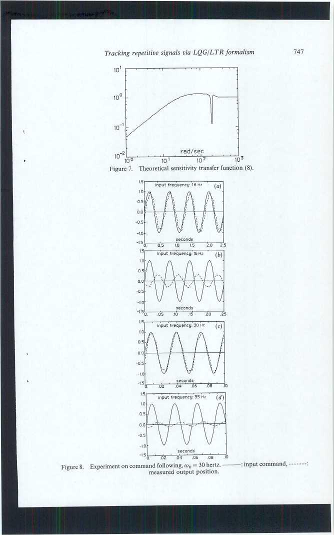
6 "\ \- 746 H. Kazerooni The: bode plot in Figs 4 and 5 show the experimental and theoretical closed loop transfer function gain and phase with unity magnitude and -360 phase at roo = 200 rad/sec. Figure 6 shows the loop transfer function where its value is large at roo = 200 rad/sec. The loop transfer function crosses over the zero db line before the frequency range of the unmodelled dynamics. Figure 7 shows the theoretical value of 10' I I I Figure 4. Experimental and theoretical closed loop transfer function gain, Gclosed(S)' UI -300 Qj Qj Qj "tj Figure Experimental and theoretical closed loop transfer function phase ~ -simulation.experiment 10- rad/sec simulation...experiment, rad/sec...i I...,.,0 10' Figure 6. Experimental and theoretical loop transfer function gain, 1G(S)Go(S)K(s)I.
7

. The system output has been attenuated and has a considerable amount of delay.")
 and the system output has been attenuated.")

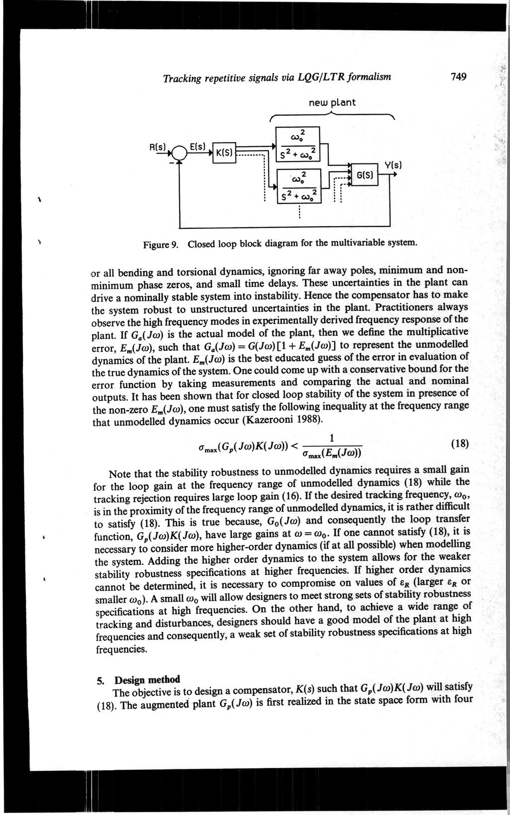
8 748 H. Kazeroonl the :sensitivity transfer function where a 'notch' filter type compensator is developed in the system for tracking. jfigure 8 shows the experimental time domain frequency response for various values of the input frequencies. Figure 8a shows the steady state response of the system when the input command is a 1.6 hertz (about 10 rad/sec) sinusoidal function. At low frequencies the system follows the input with little delay. Figure 8b shows the system response when input frequency is 16 hertz (about 100 rad/sec). The system output has been attenuated and has a considerable amount of delay. Figure 8c shows the case when the input frequency is about 30 hertz (200 rad/sec). The amplitude of the system output is almost equal to the amplitude of the input and the delay is about 360. Figllre 8d shows a case where the input command is 35 hertz (220 rad/sec) and the system output has been attenuated. These time domain experiments show that the system follows the input command with less precision at frequencies other than 30 hertz. 4. Extension to multivariable systems The design methodology can be extended to multivariable systems. We insert a second order underdamped transfer function for each input channel to increase the loop gain at (I) = (1)0(Fig. 9). This results in a diagonal augmenting transfer function matirix of the following form: Go(s) = 2 w~ 2 In (14) s +wo One must guarantee the following inequality to track the sinusoidal signals with precision of BR' O"max(I+G(Jw)Go(Jw)K(Jw»-l<BR forw=wo (15) where O"max indicates the maximum singular value of the transfer function and K(s) is the stabilizing compensator. The maximum singular value of a matrix A, O"max(A) is defined as: O"max(A) =max- where z is a non-zero vector and I "I denotes the Euclidean norm. A more conservative condition for tracking with the precision of I:R is given by (16): IAzl Izi O"max[G(Jm)Go(Jm)K(Jm)] > 1 + for ro = roo (16) 6R By inspection of Fig. 9, the closed loop transfer function matrix is: Gclosed(S) = Gp(s)K(s) [In + Gp(s)K(S)]-l (17) where Gp( Jw) = G( JW)GO( Jw). It can be shown that size of the loop transfer function, Gp(.\:)K(s), approaches infinity in the singular value sense and Gclosed(S) approaches the unity matrix when W = Wo. This leads to the exact command following of the input commands at wo. Limitations in the design of the compensator, K(s), may arise when the Idesired tracking frequency, wo, lies within or in the proximity of the frequency range of the unmodelled dynamics. One always has errors due to intentional approximation of higher order dynamics by lower order models, neglecting fast actuator and sensor dynamics, neglecting some
9
ui=on real(}..j<o i=i,2,...,n Ui~O } (19) whl~re Ai and Ui (i = 1,2,.")
=o~ real (l1.i) < 0 vt ~ 0 i=1,2,...,n } (20) whl~re l1.")
10 ~ 750 H. Kazerooni matrices of A, B, C and D. One traditional method of designing K(s) consists of two stages. The first stage concerns state feedback gain design. A state feedback gain F is designed so that the closed loop system in Fig. 10 is stable or equivalently: (}..iln-a+bf)ui=on real(}..j<o i=i,2,...,n Ui~O } (19) whl~re Ai and Ui (i = 1,2,..., n) are closed loop eigenvalues and eigenvectors of state feedback configuration. In the second stage, an observer gain H is designed to make the first stage realizable. Figure 11 shows the structure of the observer. For stability of the observer the following equality must be guaranteed. vt(l1.iln-a+hc)=o~ real (l1.i) < 0 vt ~ 0 i=1,2,...,n } (20) whl~re l1.i and vt (i = 1,2,..., n) are the closed loop eigenvalues and left eigenvectors of the observer. Combining the state feed back and observer designs (Fig. 12) yields the unique compensator transfer function matrix given by K(s) = G(sI- A + BF+ HC)-1 H (21) The closed loop system shown in Fig. 12 is stable iff the loops in Figs 10 and 11 are stable (separation principle). In this paper we take a different approach in the design of Hand F. First we design a stable H such that the loop transfer function C(sI- A)--1H in Fig. 11 meets (17). In the second stage of the compensator design a stable sta1:e feedback gain F is designed to guarantee that the final loop transfer function Gp(s)K(s) maintains the same loop shape that C(sI -A) -1 H achieved via filter design at the first stage. This is the principle behind Loop Transfer Recovery. The eigenstructure properties of LTR for a general multi-input multi-output system have been discussed in Kazerooni and Houpt (1986) and Kazerooni (1988).. c)-to! B k >!{ J x F Figure 10. State feedback configuration. ~0 ~}+t H ~~ J j--~~ c ~ Figure 11. Observer configuration.
 is true as p approaches zero for any non-singular (m x m) W matrix, jpf--+wc (22) then K(s) approaches pointwise (non-uniformly) towards (23).")
 -1 B)]-l C(sl -A)-l H (23) And since Gp(S) = C(sl -A)-l B, then Gp(s)K(s) will approach C(sl -A)-lH nonuniformly and the following are true: (a) The finite transmission zeros (Davison and")
 All the transmission zeros of the compensator K(s), cancel the transmission zeros (including ones at infinity) of the plant.")
11 Tracking repetitive signals via LQGfLTRformalism 751 D --<)~ I C Here we summarize the properties of the Loop Transfer Recovery. If F is chosen such that (22) is true as p approaches zero for any non-singular (m x m) W matrix, jpf--+wc (22) then K(s) approaches pointwise (non-uniformly) towards (23). This result shows how LQG/LTR develops a 'legal' inverse of the plant. [C(sI -A) -1 B)]-l C(sl -A)-l H (23) And since Gp(S) = C(sl -A)-l B, then Gp(s)K(s) will approach C(sl -A)-lH nonuniformly and the following are true: (a) The finite transmission zeros (Davison and Wang 1974) of the compensator K(s) are the same as the finite transmission zeros of C(sl -A)-l H. (b) All the transmission zeros of the compensator K(s), cancel the transmission zeros (including ones at infinity) of the plant. According to (b), as p approaches zero, the eigenvalues of K(s) will cancel out the transmission zeros of the plant. According to (a), as p approaches zero, the transmission zeros of K(s) will approach the transmission zeros C(sI -A) -1 H. Since the number of transmission zeros of two cascaded systems K(s) and Gp(s) is the sum of the number of transmission zeros of both systems, the transmission zeros of Gp(s)K(s) are the same as the transmission zeros of C( sl -A) -1 H. Similar arguments can be given for the poles of Gp(s)K(s). The poles of K(s) cancel out the transmission zeros of the plant; therefore the poles of Gp(s)K(s) will be the same as the poles of C(sl- A) -1 H. This argument does not prove the asymptotic equality of C(sl -A) -1 Hand Gp(s)K(s) as p approaches zero. Proof of the pointwise equality of Gp(s)K(s) and C(sl -A)-l H is best shown in Doyle and Stein (1981). The above comment concerning pole-zero cancellation explains the eigenstructure mechanism for LTR. Since pole placement and eigenvector construction in the allowable sub-space prescribes a unique value for F, one may design F via pole placement and eigenvector construction. Difficulty in using LTR will arise if the plant has some right, half-plane zeros (nonminimum-phase plant). In our proposed procedure for LTR, one should place the eigenvalues of A -B F at the transmission zeros of the plant. If the plant is in nonminimum phase, one would place some eigenvalues of A -BF on the right half-plane. The closed-loop system will not be stable if any eigenvalues of A -BF are on the right half-plane. According to the separation theorem, the eigenvalues of A -BF are also~


. As the experimental values of the loop transfer function show in Fig.")
![6, the unmodelled dynamics in plant starts at about 350 rad/sec. Using F = [0'32 0.05 1'11 0'002] and H= [-750 323 203 1763]T, the compensator K(s) of(12) results.](/docs-images/89/97932139/images/12-3.jpg "This compensator allows for a loop transfer function that is below the zero db line within the frequency range of unmodelled dynamics.")
12 752 Tracking repetitive signals via LQGfLTRformalism the eigenvalues of the closed-loop system. Therefore the sufficient condition for LTR and the stability of the closed-loop system is that the plant be minimum-phase. If the plant is non-minimum-phase, one should consider the mirror images of the right halfplane zeros as target locations for eigenvalues of A -BF. In such cases, loop transfer recovery is not guaranteed, but the closed-loop system will be stable. The limitation associated with non-minimum phase transmission zeros which has also been seen in Hoo design method was described the best in Freudenberg and Looze (1985). The above design method has been used for the design of the compensator in (12). As the experimental values of the loop transfer function show in Fig. 6, the unmodelled dynamics in plant starts at about 350 rad/sec. Using F = [0' '11 0'002] and H= [ ]T, the compensator K(s) of(12) results. This compensator allows for a loop transfer function that is below the zero db line within the frequency range of unmodelled dynamics. The compensator has three large poles to approximately cancel out the three infinite zeros of the plant. The two zeros of the compensator add lead angle to the loop transfer function to generate stability. 6. Conclusion lrhe work presented here is a simple and practical control methodology in the design of compensators that allow for tracking input signals at a particular frequency. The tracking capability at a particular frequency requires a large loop gain at that frequency. We use an undamped transfer function as a precompensator to guarantee the large size of the loop transfer function. The loop transfer function is then stabilized by a feedback compensator within the LQGfLTR formalism. A limitation will arise whelrl the tracking frequency is within or very close to the unmodelled dynamics of the systf:m. REFERENCES ATHANS, M., and STEIN, G., 1987, The LQG/LTR procedure for multivariable feedback control design. I.E.E.E. Transactions on Automatic Control, 32, 105. DAVISON, E. J., WANG, S. H., 1974, Properties and calculation of transmission zeros of linear multivariable systems. Automatica, 10, 643. DoYJ~E, J. C., and STEIN, G., 1981, Multivariable feedback design: concepts for a classical modem synthesis. I.E.E.E. Transactions on Automatic Control, 26, 4. FRELIDENBERG, J. S., and LooZE, D. P., 1985, Right half plane poles and zeros and design tradeoffs in feedback systems. I.E.E.E. Transactions on Automatic Control, 30, 555. KAZEROONI, H., 1988, Loop shaping design related to LQG/LTR for SISO minimum phase plants. International Journal of Control, 48, 241. KAZI!ROONI, H., and HouPT, P. K., 1986, On the loop transfer recovery. International Journal of Control, 43, 981. ToMIZUKA, M., 1987, Zero phase error tracking algorithm for digital control. Journal of Dynamic Systems, Measurements and Control, 109, 57. ToMIZUKA, M., CHEN, M. S., RENN, S., and TSAO, T. C., 1987, Tool positioning for non-circular cutting with lathe. Journal of Dynamic Systems, Measurements and Control, 109, 176. TSAO, T., and TOMIZUKA, M., 1988, Adaptive digital control algorithm for non-circular machining. American Control Conference, Atlanta, 115. YAMJ~MO1O, Y., and HARA, S., 1985, Stability of repetitive control systems. I.E.E.E. Conference on Decision and Control, 326.
Loop shaping design related to LQG/LTR for SISO minimum phase plants
 ., INT. J. CONTROL, 1988, YOLo 48, No.1, 241-255 Loop shaping design related to LQG/LTR for SISO minimum phase plants H. KAZEROONIt ~, One method of model-based compensator design for linear systems consists
Acceleration Feedback
 Acceleration Feedback Mechanical Engineer Modeling & Simulation Electro- Mechanics Electrical- Electronics Engineer Sensors Actuators Computer Systems Engineer Embedded Control Controls Engineer Mechatronic
Chapter 9 Robust Stability in SISO Systems 9. Introduction There are many reasons to use feedback control. As we have seen earlier, with the help of a
 Lectures on Dynamic Systems and Control Mohammed Dahleh Munther A. Dahleh George Verghese Department of Electrical Engineering and Computer Science Massachuasetts Institute of Technology c Chapter 9 Robust
Stability of CL System
 Stability of CL System Consider an open loop stable system that becomes unstable with large gain: At the point of instability, K( j) G( j) = 1 0dB K( j) G( j) K( j) G( j) K( j) G( j) =± 180 o 180 o Closed
State Regulator. Advanced Control. design of controllers using pole placement and LQ design rules
 Advanced Control State Regulator Scope design of controllers using pole placement and LQ design rules Keywords pole placement, optimal control, LQ regulator, weighting matrixes Prerequisites Contact state
Today (10/23/01) Today. Reading Assignment: 6.3. Gain/phase margin lead/lag compensator Ref. 6.4, 6.7, 6.10
 Today. Reading Assignment: 6.3. Gain/phase margin lead/lag compensator Ref. 6.4, 6.7, 6.10") Today Today (10/23/01) Gain/phase margin lead/lag compensator Ref. 6.4, 6.7, 6.10 Reading Assignment: 6.3 Last Time In the last lecture, we discussed control design through shaping of the loop gain GK:
Today Today (10/23/01) Gain/phase margin lead/lag compensator Ref. 6.4, 6.7, 6.10 Reading Assignment: 6.3 Last Time In the last lecture, we discussed control design through shaping of the loop gain GK:
D(s) G(s) A control system design definition
 G(s) A control system design definition") R E Compensation D(s) U Plant G(s) Y Figure 7. A control system design definition x x x 2 x 2 U 2 s s 7 2 Y Figure 7.2 A block diagram representing Eq. (7.) in control form z U 2 s z Y 4 z 2 s z 2 3 Figure
R E Compensation D(s) U Plant G(s) Y Figure 7. A control system design definition x x x 2 x 2 U 2 s s 7 2 Y Figure 7.2 A block diagram representing Eq. (7.) in control form z U 2 s z Y 4 z 2 s z 2 3 Figure
Singular Value Decomposition Analysis
 Singular Value Decomposition Analysis Singular Value Decomposition Analysis Introduction Introduce a linear algebra tool: singular values of a matrix Motivation Why do we need singular values in MIMO control
Repetitive control : Power Electronics. Applications
 Repetitive control : Power Electronics Applications Ramon Costa Castelló Advanced Control of Energy Systems (ACES) Instituto de Organización y Control (IOC) Universitat Politècnica de Catalunya (UPC) Barcelona,
Video 5.1 Vijay Kumar and Ani Hsieh
 Video 5.1 Vijay Kumar and Ani Hsieh Robo3x-1.1 1 The Purpose of Control Input/Stimulus/ Disturbance System or Plant Output/ Response Understand the Black Box Evaluate the Performance Change the Behavior
Design of Robust Controllers for Gas Turbine Engines
 E THE AMERICAN SOCIETY OF MECHANICAL ENGINEERS y^ 345 E. 47 St., New York, N.Y. 117 s The Society shall not be responsible for statements or opinions advanced in papers or in discussion at meetings of
Linear State Feedback Controller Design
 Assignment For EE5101 - Linear Systems Sem I AY2010/2011 Linear State Feedback Controller Design Phang Swee King A0033585A Email: king@nus.edu.sg NGS/ECE Dept. Faculty of Engineering National University
Chapter 2. Classical Control System Design. Dutch Institute of Systems and Control
 Chapter 2 Classical Control System Design Overview Ch. 2. 2. Classical control system design Introduction Introduction Steady-state Steady-state errors errors Type Type k k systems systems Integral Integral
Root Locus. Motivation Sketching Root Locus Examples. School of Mechanical Engineering Purdue University. ME375 Root Locus - 1
 Root Locus Motivation Sketching Root Locus Examples ME375 Root Locus - 1 Servo Table Example DC Motor Position Control The block diagram for position control of the servo table is given by: D 0.09 Position
Control Systems Design
 ELEC4410 Control Systems Design Lecture 18: State Feedback Tracking and State Estimation Julio H. Braslavsky julio@ee.newcastle.edu.au School of Electrical Engineering and Computer Science Lecture 18:
FEL3210 Multivariable Feedback Control
 FEL3210 Multivariable Feedback Control Lecture 5: Uncertainty and Robustness in SISO Systems [Ch.7-(8)] Elling W. Jacobsen, Automatic Control Lab, KTH Lecture 5:Uncertainty and Robustness () FEL3210 MIMO
Introduction to Feedback Control
 Introduction to Feedback Control Control System Design Why Control? Open-Loop vs Closed-Loop (Feedback) Why Use Feedback Control? Closed-Loop Control System Structure Elements of a Feedback Control System
Chapter 7 Interconnected Systems and Feedback: Well-Posedness, Stability, and Performance 7. Introduction Feedback control is a powerful approach to o
 Lectures on Dynamic Systems and Control Mohammed Dahleh Munther A. Dahleh George Verghese Department of Electrical Engineering and Computer Science Massachuasetts Institute of Technology c Chapter 7 Interconnected
Fundamental Design Limitations of the General Control Configuration
 IEEE TRANSACTIONS ON AUTOMATIC CONTROL, VOL 48, NO 8, AUGUST 2003 1355 Fundamental Design Limitations of the General Control Configuration Jim S Freudenberg, Fellow, IEEE, C V Hollot, Senior Member, IEEE,
Observer design for rotating shafts excited by unbalances
 Observer design for rotating shafts excited by unbalances R. S. Schittenhelm, Z. Wang, S. Rinderknecht Institute for Mechatronic Systems in Mechanical Engineering, Technische Universität Darmstadt, Germany
Lecture 12. Upcoming labs: Final Exam on 12/21/2015 (Monday)10:30-12:30
10:30-12:30") 289 Upcoming labs: Lecture 12 Lab 20: Internal model control (finish up) Lab 22: Force or Torque control experiments [Integrative] (2-3 sessions) Final Exam on 12/21/2015 (Monday)10:30-12:30 Today: Recap
289 Upcoming labs: Lecture 12 Lab 20: Internal model control (finish up) Lab 22: Force or Torque control experiments [Integrative] (2-3 sessions) Final Exam on 12/21/2015 (Monday)10:30-12:30 Today: Recap
CDS 101/110a: Lecture 8-1 Frequency Domain Design
 CDS 11/11a: Lecture 8-1 Frequency Domain Design Richard M. Murray 17 November 28 Goals: Describe canonical control design problem and standard performance measures Show how to use loop shaping to achieve
ECSE 4962 Control Systems Design. A Brief Tutorial on Control Design
 ECSE 4962 Control Systems Design A Brief Tutorial on Control Design Instructor: Professor John T. Wen TA: Ben Potsaid http://www.cat.rpi.edu/~wen/ecse4962s04/ Don t Wait Until The Last Minute! You got
Feedback Control of Linear SISO systems. Process Dynamics and Control
 Feedback Control of Linear SISO systems Process Dynamics and Control 1 Open-Loop Process The study of dynamics was limited to open-loop systems Observe process behavior as a result of specific input signals
Lecture 7 (Weeks 13-14)
") Lecture 7 (Weeks 13-14) Introduction to Multivariable Control (SP - Chapters 3 & 4) Eugenio Schuster schuster@lehigh.edu Mechanical Engineering and Mechanics Lehigh University Lecture 7 (Weeks 13-14) p.
Lecture 7 (Weeks 13-14) Introduction to Multivariable Control (SP - Chapters 3 & 4) Eugenio Schuster schuster@lehigh.edu Mechanical Engineering and Mechanics Lehigh University Lecture 7 (Weeks 13-14) p.
FEEDBACK CONTROL SYSTEMS
 FEEDBAC CONTROL SYSTEMS. Control System Design. Open and Closed-Loop Control Systems 3. Why Closed-Loop Control? 4. Case Study --- Speed Control of a DC Motor 5. Steady-State Errors in Unity Feedback Control
Control System Design
 ELEC ENG 4CL4: Control System Design Notes for Lecture #24 Wednesday, March 10, 2004 Dr. Ian C. Bruce Room: CRL-229 Phone ext.: 26984 Email: ibruce@mail.ece.mcmaster.ca Remedies We next turn to the question
MEM 355 Performance Enhancement of Dynamical Systems
 MEM 355 Performance Enhancement of Dynamical Systems Frequency Domain Design Intro Harry G. Kwatny Department of Mechanical Engineering & Mechanics Drexel University /5/27 Outline Closed Loop Transfer
Dr Ian R. Manchester Dr Ian R. Manchester AMME 3500 : Review
 Week Date Content Notes 1 6 Mar Introduction 2 13 Mar Frequency Domain Modelling 3 20 Mar Transient Performance and the s-plane 4 27 Mar Block Diagrams Assign 1 Due 5 3 Apr Feedback System Characteristics
magnitude [db] phase [deg] frequency [Hz] feedforward motor load -
![magnitude [db] phase [deg] frequency [Hz] feedforward motor load -](/thumbs/80/81052498.jpg "magnitude [db] phase [deg] frequency [Hz] feedforward motor load -") ITERATIVE LEARNING CONTROL OF INDUSTRIAL MOTION SYSTEMS Maarten Steinbuch and René van de Molengraft Eindhoven University of Technology, Faculty of Mechanical Engineering, Systems and Control Group, P.O.
ITERATIVE LEARNING CONTROL OF INDUSTRIAL MOTION SYSTEMS Maarten Steinbuch and René van de Molengraft Eindhoven University of Technology, Faculty of Mechanical Engineering, Systems and Control Group, P.O.
Positioning Servo Design Example
 Positioning Servo Design Example 1 Goal. The goal in this design example is to design a control system that will be used in a pick-and-place robot to move the link of a robot between two positions. Usually
Course Summary. The course cannot be summarized in one lecture.
 Course Summary Unit 1: Introduction Unit 2: Modeling in the Frequency Domain Unit 3: Time Response Unit 4: Block Diagram Reduction Unit 5: Stability Unit 6: Steady-State Error Unit 7: Root Locus Techniques
School of Mechanical Engineering Purdue University. ME375 Feedback Control - 1
 Introduction to Feedback Control Control System Design Why Control? Open-Loop vs Closed-Loop (Feedback) Why Use Feedback Control? Closed-Loop Control System Structure Elements of a Feedback Control System
Let the plant and controller be described as:-
 Summary of Fundamental Limitations in Feedback Design (LTI SISO Systems) From Chapter 6 of A FIRST GRADUATE COURSE IN FEEDBACK CONTROL By J. S. Freudenberg (Winter 2008) Prepared by: Hammad Munawar (Institute
(a) Find the transfer function of the amplifier. Ans.: G(s) =
 Find the transfer function of the amplifier. Ans.: G(s) =") 126 INTRDUCTIN T CNTR ENGINEERING 10( s 1) (a) Find the transfer function of the amplifier. Ans.: (. 02s 1)(. 001s 1) (b) Find the expected percent overshoot for a step input for the closed-loop system
126 INTRDUCTIN T CNTR ENGINEERING 10( s 1) (a) Find the transfer function of the amplifier. Ans.: (. 02s 1)(. 001s 1) (b) Find the expected percent overshoot for a step input for the closed-loop system
Appendix A: Exercise Problems on Classical Feedback Control Theory (Chaps. 1 and 2)
") Appendix A: Exercise Problems on Classical Feedback Control Theory (Chaps. 1 and 2) For all calculations in this book, you can use the MathCad software or any other mathematical software that you are familiar
Appendix A: Exercise Problems on Classical Feedback Control Theory (Chaps. 1 and 2) For all calculations in this book, you can use the MathCad software or any other mathematical software that you are familiar
Chapter 15 - Solved Problems
 Chapter 5 - Solved Problems Solved Problem 5.. Contributed by - Alvaro Liendo, Universidad Tecnica Federico Santa Maria, Consider a plant having a nominal model given by G o (s) = s + 2 The aim of the
Control System Design
 ELEC ENG 4CL4: Control System Design Notes for Lecture #36 Dr. Ian C. Bruce Room: CRL-229 Phone ext.: 26984 Email: ibruce@mail.ece.mcmaster.ca Friday, April 4, 2003 3. Cascade Control Next we turn to an
Rejection of fixed direction disturbances in multivariable electromechanical motion systems
 Rejection of fixed direction disturbances in multivariable electromechanical motion systems Matthijs Boerlage Rick Middleton Maarten Steinbuch, Bram de Jager Technische Universiteit Eindhoven, Eindhoven,
Laplace Transform Analysis of Signals and Systems
 Laplace Transform Analysis of Signals and Systems Transfer Functions Transfer functions of CT systems can be found from analysis of Differential Equations Block Diagrams Circuit Diagrams 5/10/04 M. J.
Automatic Control 2. Loop shaping. Prof. Alberto Bemporad. University of Trento. Academic year
 Automatic Control 2 Loop shaping Prof. Alberto Bemporad University of Trento Academic year 21-211 Prof. Alberto Bemporad (University of Trento) Automatic Control 2 Academic year 21-211 1 / 39 Feedback
ELECTRONICS & COMMUNICATIONS DEP. 3rd YEAR, 2010/2011 CONTROL ENGINEERING SHEET 5 Lead-Lag Compensation Techniques
 CAIRO UNIVERSITY FACULTY OF ENGINEERING ELECTRONICS & COMMUNICATIONS DEP. 3rd YEAR, 00/0 CONTROL ENGINEERING SHEET 5 Lead-Lag Compensation Techniques [] For the following system, Design a compensator such
EEE582 Homework Problems
 EEE582 Homework Problems HW. Write a state-space realization of the linearized model for the cruise control system around speeds v = 4 (Section.3, http://tsakalis.faculty.asu.edu/notes/models.pdf). Use
CURRENT LOOPS George W. Younkin, P.E. Life Fellow IEEE Industrial Controls Research, Inc. Fond du Lac, Wisconsin
 CURRENT LOOPS George W. Younkin, P.E. Life Fellow IEEE Industrial Controls Research, Inc. Fond du Lac, Wisconsin All industrial servo drives require some form of compensation often referred to as proportional,
Chapter 7 - Solved Problems
 Chapter 7 - Solved Problems Solved Problem 7.1. A continuous time system has transfer function G o (s) given by G o (s) = B o(s) A o (s) = 2 (s 1)(s + 2) = 2 s 2 + s 2 (1) Find a controller of minimal
TWO- PHASE APPROACH TO DESIGN ROBUST CONTROLLER FOR UNCERTAIN INTERVAL SYSTEM USING GENETIC ALGORITHM
 International Journal of Electrical and Electronics Engineering Research (IJEEER) ISSN:2250-155X Vol.2, Issue 2 June 2012 27-38 TJPRC Pvt. Ltd., TWO- PHASE APPROACH TO DESIGN ROBUST CONTROLLER FOR UNCERTAIN
Analysis of SISO Control Loops
 Chapter 5 Analysis of SISO Control Loops Topics to be covered For a given controller and plant connected in feedback we ask and answer the following questions: Is the loop stable? What are the sensitivities
Chapter 5. Standard LTI Feedback Optimization Setup. 5.1 The Canonical Setup
 Chapter 5 Standard LTI Feedback Optimization Setup Efficient LTI feedback optimization algorithms comprise a major component of modern feedback design approach: application problems involving complex models
Problem Set 4 Solution 1
 Massachusetts Institute of Technology Department of Electrical Engineering and Computer Science 6.245: MULTIVARIABLE CONTROL SYSTEMS by A. Megretski Problem Set 4 Solution Problem 4. For the SISO feedback
Design Methods for Control Systems
 Design Methods for Control Systems Maarten Steinbuch TU/e Gjerrit Meinsma UT Dutch Institute of Systems and Control Winter term 2002-2003 Schedule November 25 MSt December 2 MSt Homework # 1 December 9
Lecture 6. Chapter 8: Robust Stability and Performance Analysis for MIMO Systems. Eugenio Schuster.
 Lecture 6 Chapter 8: Robust Stability and Performance Analysis for MIMO Systems Eugenio Schuster schuster@lehigh.edu Mechanical Engineering and Mechanics Lehigh University Lecture 6 p. 1/73 6.1 General
Chapter Stability Robustness Introduction Last chapter showed how the Nyquist stability criterion provides conditions for the stability robustness of
 Lectures on Dynamic Systems and Control Mohammed Dahleh Munther A Dahleh George Verghese Department of Electrical Engineering and Computer Science Massachuasetts Institute of Technology c Chapter Stability
PERIODIC signals are commonly experienced in industrial
 IEEE TRANSACTIONS ON CONTROL SYSTEMS TECHNOLOGY, VOL. 15, NO. 2, MARCH 2007 369 Repetitive Learning Control of Nonlinear Continuous-Time Systems Using Quasi-Sliding Mode Xiao-Dong Li, Tommy W. S. Chow,
REPETITIVE LEARNING OF BACKSTEPPING CONTROLLED NONLINEAR ELECTROHYDRAULIC MATERIAL TESTING SYSTEM 1. Seunghyeokk James Lee 2, Tsu-Chin Tsao
 REPETITIVE LEARNING OF BACKSTEPPING CONTROLLED NONLINEAR ELECTROHYDRAULIC MATERIAL TESTING SYSTEM Seunghyeokk James Lee, Tsu-Chin Tsao Mechanical and Aerospace Engineering Department University of California
H-infinity Model Reference Controller Design for Magnetic Levitation System
 H.I. Ali Control and Systems Engineering Department, University of Technology Baghdad, Iraq 6043@uotechnology.edu.iq H-infinity Model Reference Controller Design for Magnetic Levitation System Abstract-
Subject: Optimal Control Assignment-1 (Related to Lecture notes 1-10)
") Subject: Optimal Control Assignment- (Related to Lecture notes -). Design a oil mug, shown in fig., to hold as much oil possible. The height and radius of the mug should not be more than 6cm. The mug must
Subject: Optimal Control Assignment- (Related to Lecture notes -). Design a oil mug, shown in fig., to hold as much oil possible. The height and radius of the mug should not be more than 6cm. The mug must
Introduction to Control (034040) lecture no. 2
 lecture no. 2") Introduction to Control (034040) lecture no. 2 Leonid Mirkin Faculty of Mechanical Engineering Technion IIT Setup: Abstract control problem to begin with y P(s) u where P is a plant u is a control signal
Introduction to Control (034040) lecture no. 2 Leonid Mirkin Faculty of Mechanical Engineering Technion IIT Setup: Abstract control problem to begin with y P(s) u where P is a plant u is a control signal
Control Systems Design
 ELEC4410 Control Systems Design Lecture 3, Part 2: Introduction to Affine Parametrisation School of Electrical Engineering and Computer Science Lecture 3, Part 2: Affine Parametrisation p. 1/29 Outline
Fall 線性系統 Linear Systems. Chapter 08 State Feedback & State Estimators (SISO) Feng-Li Lian. NTU-EE Sep07 Jan08
 Feng-Li Lian. NTU-EE Sep07 Jan08") Fall 2007 線性系統 Linear Systems Chapter 08 State Feedback & State Estimators (SISO) Feng-Li Lian NTU-EE Sep07 Jan08 Materials used in these lecture notes are adopted from Linear System Theory & Design, 3rd.
Fall 2007 線性系統 Linear Systems Chapter 08 State Feedback & State Estimators (SISO) Feng-Li Lian NTU-EE Sep07 Jan08 Materials used in these lecture notes are adopted from Linear System Theory & Design, 3rd.
EEE 184: Introduction to feedback systems
 EEE 84: Introduction to feedback systems Summary 6 8 8 x 7 7 6 Level() 6 5 4 4 5 5 time(s) 4 6 8 Time (seconds) Fig.. Illustration of BIBO stability: stable system (the input is a unit step) Fig.. step)
A DESIGN METHOD FOR SIMPLE REPETITIVE CONTROLLERS WITH SPECIFIED INPUT-OUTPUT CHARACTERISTIC
 International Journal of Innovative Computing, Information Control ICIC International c 202 ISSN 349-498 Volume 8, Number 7(A), July 202 pp. 4883 4899 A DESIGN METHOD FOR SIMPLE REPETITIVE CONTROLLERS
KINGS COLLEGE OF ENGINEERING DEPARTMENT OF ELECTRONICS AND COMMUNICATION ENGINEERING
 KINGS COLLEGE OF ENGINEERING DEPARTMENT OF ELECTRONICS AND COMMUNICATION ENGINEERING QUESTION BANK SUB.NAME : CONTROL SYSTEMS BRANCH : ECE YEAR : II SEMESTER: IV 1. What is control system? 2. Define open
Simple Learning Control Made Practical by Zero-Phase Filtering: Applications to Robotics
 IEEE TRANSACTIONS ON CIRCUITS AND SYSTEMS I: FUNDAMENTAL THEORY AND APPLICATIONS, VOL 49, NO 6, JUNE 2002 753 Simple Learning Control Made Practical by Zero-Phase Filtering: Applications to Robotics Haluk
CONTROL DESIGN FOR SET POINT TRACKING
 Chapter 5 CONTROL DESIGN FOR SET POINT TRACKING In this chapter, we extend the pole placement, observer-based output feedback design to solve tracking problems. By tracking we mean that the output is commanded
Chapter 2 Review of Linear and Nonlinear Controller Designs
 Chapter 2 Review of Linear and Nonlinear Controller Designs This Chapter reviews several flight controller designs for unmanned rotorcraft. 1 Flight control systems have been proposed and tested on a wide
DISTURBANCE ATTENUATION IN A MAGNETIC LEVITATION SYSTEM WITH ACCELERATION FEEDBACK
 DISTURBANCE ATTENUATION IN A MAGNETIC LEVITATION SYSTEM WITH ACCELERATION FEEDBACK Feng Tian Department of Mechanical Engineering Marquette University Milwaukee, WI 53233 USA Email: feng.tian@mu.edu Kevin
(b) A unity feedback system is characterized by the transfer function. Design a suitable compensator to meet the following specifications:
 A unity feedback system is characterized by the transfer function. Design a suitable compensator to meet the following specifications:") 1. (a) The open loop transfer function of a unity feedback control system is given by G(S) = K/S(1+0.1S)(1+S) (i) Determine the value of K so that the resonance peak M r of the system is equal to 1.4.
1. (a) The open loop transfer function of a unity feedback control system is given by G(S) = K/S(1+0.1S)(1+S) (i) Determine the value of K so that the resonance peak M r of the system is equal to 1.4.
Introduction. Performance and Robustness (Chapter 1) Advanced Control Systems Spring / 31
 Advanced Control Systems Spring / 31") Introduction Classical Control Robust Control u(t) y(t) G u(t) G + y(t) G : nominal model G = G + : plant uncertainty Uncertainty sources : Structured : parametric uncertainty, multimodel uncertainty Unstructured
Introduction Classical Control Robust Control u(t) y(t) G u(t) G + y(t) G : nominal model G = G + : plant uncertainty Uncertainty sources : Structured : parametric uncertainty, multimodel uncertainty Unstructured
Position Control Using Acceleration- Based Identification and Feedback With Unknown Measurement Bias
 Position Control Using Acceleration- Based Identification and Feedback With Unknown Measurement Bias Jaganath Chandrasekar e-mail: jchandra@umich.edu Dennis S. Bernstein e-mail: dsbaero@umich.edu Department
Lecture 1: Feedback Control Loop
 Lecture : Feedback Control Loop Loop Transfer function The standard feedback control system structure is depicted in Figure. This represend(t) n(t) r(t) e(t) u(t) v(t) η(t) y(t) F (s) C(s) P (s) Figure
Control System Design
 ELEC4410 Control System Design Lecture 19: Feedback from Estimated States and Discrete-Time Control Design Julio H. Braslavsky julio@ee.newcastle.edu.au School of Electrical Engineering and Computer Science
MAE 143B - Homework 9
 MAE 43B - Homework 9 7.2 2 2 3.8.6.4.2.2 9 8 2 2 3 a) G(s) = (s+)(s+).4.6.8.2.2.4.6.8. Polar plot; red for negative ; no encirclements of, a.s. under unit feedback... 2 2 3. 4 9 2 2 3 h) G(s) = s+ s(s+)..2.4.6.8.2.4
Intro to Frequency Domain Design
 Intro to Frequency Domain Design MEM 355 Performance Enhancement of Dynamical Systems Harry G. Kwatny Department of Mechanical Engineering & Mechanics Drexel University Outline Closed Loop Transfer Functions
Enhancing Transient Response of Asymptotic Regulation with Disturbance Onset
 211 American Control Conference on O'Farrell Street, San Francisco, CA, USA June 29 - July 1, 211 Enhancing Transient Response of Asymptotic Regulation with Disturbance Onset Kevin C. Chu and Tsu-Chin
Lifted approach to ILC/Repetitive Control
 Lifted approach to ILC/Repetitive Control Okko H. Bosgra Maarten Steinbuch TUD Delft Centre for Systems and Control TU/e Control System Technology Dutch Institute of Systems and Control DISC winter semester
(Refer Slide Time: 00:01:30 min)
") Control Engineering Prof. M. Gopal Department of Electrical Engineering Indian Institute of Technology, Delhi Lecture - 3 Introduction to Control Problem (Contd.) Well friends, I have been giving you various
Control Engineering Prof. M. Gopal Department of Electrical Engineering Indian Institute of Technology, Delhi Lecture - 3 Introduction to Control Problem (Contd.) Well friends, I have been giving you various
6.245: MULTIVARIABLE CONTROL SYSTEMS by A. Megretski. Solutions to Problem Set 1 1. Massachusetts Institute of Technology
 Massachusetts Institute of Technology Department of Electrical Engineering and Computer Science 6.245: MULTIVARIABLE CONTROL SYSTEMS by A. Megretski Solutions to Problem Set 1 1 Problem 1.1T Consider the
Control of Manufacturing Processes
 Control of Manufacturing Processes Subject 2.830 Spring 2004 Lecture #18 Basic Control Loop Analysis" April 15, 2004 Revisit Temperature Control Problem τ dy dt + y = u τ = time constant = gain y ss =
EECE 460 : Control System Design
 EECE 460 : Control System Design SISO Pole Placement Guy A. Dumont UBC EECE January 2011 Guy A. Dumont (UBC EECE) EECE 460: Pole Placement January 2011 1 / 29 Contents 1 Preview 2 Polynomial Pole Placement
Lecture 13: Internal Model Principle and Repetitive Control
 ME 233, UC Berkeley, Spring 2014 Xu Chen Lecture 13: Internal Model Principle and Repetitive Control Big picture review of integral control in PID design example: 0 Es) C s) Ds) + + P s) Y s) where P s)
Exam. 135 minutes + 15 minutes reading time
 Exam January 23, 27 Control Systems I (5-59-L) Prof. Emilio Frazzoli Exam Exam Duration: 35 minutes + 5 minutes reading time Number of Problems: 45 Number of Points: 53 Permitted aids: Important: 4 pages
Robust Internal Model Control for Impulse Elimination of Singular Systems
 International Journal of Control Science and Engineering ; (): -7 DOI:.59/j.control.. Robust Internal Model Control for Impulse Elimination of Singular Systems M. M. Share Pasandand *, H. D. Taghirad Department
Application of Neuro Fuzzy Reduced Order Observer in Magnetic Bearing Systems
 Application of Neuro Fuzzy Reduced Order Observer in Magnetic Bearing Systems M. A., Eltantawie, Member, IAENG Abstract Adaptive Neuro-Fuzzy Inference System (ANFIS) is used to design fuzzy reduced order
Internal Model Control of A Class of Continuous Linear Underactuated Systems
 Internal Model Control of A Class of Continuous Linear Underactuated Systems Asma Mezzi Tunis El Manar University, Automatic Control Research Laboratory, LA.R.A, National Engineering School of Tunis (ENIT),
Computer Aided Control Design
 Computer Aided Control Design Project-Lab 3 Automatic Control Basic Course, EL1000/EL1100/EL1120 Revised August 18, 2008 Modified version of laboration developed by Håkan Fortell and Svante Gunnarsson
R10 JNTUWORLD B 1 M 1 K 2 M 2. f(t) Figure 1
 Figure 1") Code No: R06 R0 SET - II B. Tech II Semester Regular Examinations April/May 03 CONTROL SYSTEMS (Com. to EEE, ECE, EIE, ECC, AE) Time: 3 hours Max. Marks: 75 Answer any FIVE Questions All Questions carry
Code No: R06 R0 SET - II B. Tech II Semester Regular Examinations April/May 03 CONTROL SYSTEMS (Com. to EEE, ECE, EIE, ECC, AE) Time: 3 hours Max. Marks: 75 Answer any FIVE Questions All Questions carry
Lyapunov Stability of Linear Predictor Feedback for Distributed Input Delays
 IEEE TRANSACTIONS ON AUTOMATIC CONTROL VOL. 56 NO. 3 MARCH 2011 655 Lyapunov Stability of Linear Predictor Feedback for Distributed Input Delays Nikolaos Bekiaris-Liberis Miroslav Krstic In this case system
High Precision Control of Ball Screw Driven Stage Using Repetitive Control with Sharp Roll-off Learning Filter
 High Precision Control of Ball Screw Driven Stage Using Repetitive Control with Sharp Roll-off Learning Filter Tadashi Takemura and Hiroshi Fujimoto The University of Tokyo --, Kashiwanoha, Kashiwa, Chiba,
Control System Design
 ELEC ENG 4CL4: Control System Design Notes for Lecture #11 Wednesday, January 28, 2004 Dr. Ian C. Bruce Room: CRL-229 Phone ext.: 26984 Email: ibruce@mail.ece.mcmaster.ca Relative Stability: Stability
Optimal Plant Shaping for High Bandwidth Disturbance Rejection in Discrete Disturbance Observers
 Optimal Plant Shaping for High Bandwidth Disturbance Rejection in Discrete Disturbance Observers Xu Chen and Masayoshi Tomiuka Abstract The Qfilter cutoff frequency in a Disturbance Observer DOB) is restricted
Control Systems 2. Lecture 4: Sensitivity function limits. Roy Smith
 Control Systems 2 Lecture 4: Sensitivity function limits Roy Smith 2017-3-14 4.1 Input-output controllability Control design questions: 1. How well can the plant be controlled? 2. What control structure
An Analysis and Synthesis of Internal Model Principle Type Controllers
 29 American Control Conference Hyatt Regency Riverfront, St. Louis, MO, USA June -2, 29 WeA5.6 An Analysis and Synthesis of Internal Model Principle Type Controllers Yigang Wang, Kevin C. Chu and Tsu-Chin
CHAPTER 7 STEADY-STATE RESPONSE ANALYSES
 CHAPTER 7 STEADY-STATE RESPONSE ANALYSES 1. Introduction The steady state error is a measure of system accuracy. These errors arise from the nature of the inputs, system type and from nonlinearities of
sc Control Systems Design Q.1, Sem.1, Ac. Yr. 2010/11
 sc46 - Control Systems Design Q Sem Ac Yr / Mock Exam originally given November 5 9 Notes: Please be reminded that only an A4 paper with formulas may be used during the exam no other material is to be
Uncertainty and Robustness for SISO Systems
 Uncertainty and Robustness for SISO Systems ELEC 571L Robust Multivariable Control prepared by: Greg Stewart Outline Nature of uncertainty (models and signals). Physical sources of model uncertainty. Mathematical
Presentation Topic 1: Feedback Control. Copyright 1998 DLMattern
 Presentation Topic 1: Feedback Control Outline Feedback Terminology Purpose of Feedback Limitations of Feedback Linear Control Design Techniques Nonlinear Control Design Techniques Rapid Prototyping Environments
A FEEDBACK STRUCTURE WITH HIGHER ORDER DERIVATIVES IN REGULATOR. Ryszard Gessing
 A FEEDBACK STRUCTURE WITH HIGHER ORDER DERIVATIVES IN REGULATOR Ryszard Gessing Politechnika Śl aska Instytut Automatyki, ul. Akademicka 16, 44-101 Gliwice, Poland, fax: +4832 372127, email: gessing@ia.gliwice.edu.pl
Observer Based Friction Cancellation in Mechanical Systems
 2014 14th International Conference on Control, Automation and Systems (ICCAS 2014) Oct. 22 25, 2014 in KINTEX, Gyeonggi-do, Korea Observer Based Friction Cancellation in Mechanical Systems Caner Odabaş
Control of Electromechanical Systems
 Control of Electromechanical Systems November 3, 27 Exercise Consider the feedback control scheme of the motor speed ω in Fig., where the torque actuation includes a time constant τ A =. s and a disturbance
THE PARAMETERIZATION OF ALL ROBUST STABILIZING MULTI-PERIOD REPETITIVE CONTROLLERS FOR MIMO TD PLANTS WITH THE SPECIFIED INPUT-OUTPUT CHARACTERISTIC
 International Journal of Innovative Computing, Information Control ICIC International c 218 ISSN 1349-4198 Volume 14, Number 2, April 218 pp. 387 43 THE PARAMETERIZATION OF ALL ROBUST STABILIZING MULTI-PERIOD