F01 D S F01 F01 F01. Vacuum Ejector Box Type (Built in Silencer)/Body Ported Type Series ZH. How to Order. Product Recommendation.
|
|
|
- Miranda Shelton
- 5 years ago
- Views:
Transcription


1 2 Series ZH jector jector ox Type (uilt in Silencer)/ody Ported Type Series ZH eatures Symbol ompact and lightweight desing. hoice of nozzle diameters. Standard or low vacuum pressure options. One touch or threaded ports for easy connection in a system. Mounting holes available on all units to fix to machinery. ody ported style (without silencer) ZH How to Order ox type (uilt-in silencer) ody ported type (Without silencer) Nozzle diameter mmø 0. mmø.0 mmø 3.3 mmø. mmø. mmø mmø Product ecommendation One touch fittings only Threaded port included ZH 0 S 0 0 ZH 0 S L S Maximum vacuum pressure kpa kpa SUP. port size Symbol Size Style ø ø ø ø2 G G G3 One-touch One-touch One-touch One-touch Screw-in Screw-in Screw-in ox style (uilt-in silencer) ZH port size Symbol Size Style 0 ø One-touch ø One-touch 2 ø2 One-touch ø One-touch 0 G Screw-in 02 G Screw-in 03 G3 Screw-in 0 G 2 Screw-in H. port size Symbol Size Style 0 ø One-touch 0 ø One-touch ø One-touch 2 ø2 One-touch ø One-touch 0 G Screw-in 02 G Screw-in 03 G3 Screw-in 0 G 2 Screw-in Note) See dimensions tables for all combinations available. If a part number is not present there it cannot be ordered. Stocked items for fast delivery elated Products ZH0S-0-0 ZH0S-0-0 ZH0S-0-0 ZH0S ZH0S ZH0S-0-0 ZH0S-0-0 ZH0S ZH0S ZHS-0-0 ZHS-0-0 ZHS-0-0 ZHS ZHS ZH3S-0- ZH3S-0-02 ZH3S-0-02 ZH3S-0-- ZH3S ZHS--2-2 ZHS ZH20S-2-- ZH20S Series 0-3 Port alve - page 33 Series ZZ - ir Suction ilter - Series ZPT - Pad - Series ZP2 - Pad - page Series PM - low Switch - page 29 Series ZS0()/IS0- Switch - page 23 Series GZ - Pressure Gauge for - Series - ir Preparation - page Series TU - Tubing - page 223 Series KQ2 - ittings - page 22 Specifications Nozzle diameter [mm] ZH ZH0 ZH ZH3 ZH0 ZH0 ZH ZH3 ZH ZH ZH ody type ox type (uilt-in silencer) ody ported type (Without silencer) ody ported type (Without silencer) Max. vacuum pressure Maximum suction flow rate ir consumption onnection Weight [kpa] [l/min (N)] [l/min (N)] (One-touch/Screw-in) [g] Type S Type L Type S Type L Type S/Type L SUP H ø/ ø/ ø/ ø/ 3 ø/ ø/ ø/ ø/ ø/ ø/ 0 0 ø/ ø/ ø/ 2 9 ø/ 3 ø2/ 3 ø2/ 3 3 ø2/ 3 3 ø2/ 3 ø/ 2 ø/ 2 9 Supply pressure: 0. MPa.

![vacuum pressure: kpa low haracteristics pressure pressure [kpa] ir consumption Suction flow rate Suction flow rate [l/min [N]] ir](/docs-images/87/95905231/images/2-1.jpg "consumption [l/min [N]] pressure [kpa] pressure [kpa] pressure ir consumption Suction flow rate Suction flow rate [l/min [N]] ir")
![consumption [l/min [N]] pressure [kpa] Supply pressure [MPa] Suction flow rate [l/min [N]] Supply pressure [MPa] Suction flow rate [l/min](/docs-images/87/95905231/images/2-2.jpg "[N]] ZH0S xhaust haracteristics Max.")
![vacuum pressure: kpa low haracteristics pressure [kpa] pressure ir consumption Suction flow rate Suction flow rate [l/min [N]] ir [N]]](/docs-images/87/95905231/images/2-3.jpg "ZHS xhaust haracteristics Max. vacuum pressure: kpa low haracteristics ZHL xhaust haracteristics Max.")
![consumption[l/min [N]] pressure [kpa] pressure [kpa] pressure ir consumption Suction flow rate Suction flow rate[l/min [N]] ir [N]] ZH3S](/docs-images/87/95905231/images/2-4.jpg "xhaust haracteristics Max. vacuum pressure: kpa low haracteristics ZH3L xhaust haracteristics Max.")
![consumption [l/min [N]] pressure [kpa] pressure [kpa] ir consumption pressure Suction flow rate Suction flow rate [l/min [N]] ir [N]] or](/docs-images/87/95905231/images/2-5.jpg "more product options and details see our specific catalogues or on-line information.")
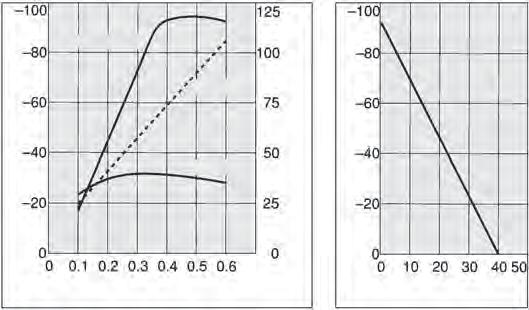
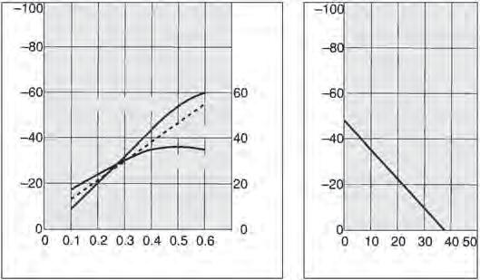
2 jector Series ZH 2 low haracteristics The flow characteristics correspond to a supply pressure of 0. MPa. ZH0S xhaust haracteristics Max. vacuum pressure: kpa low haracteristics ZH0L xhaust haracteristics Max. vacuum pressure: kpa low haracteristics pressure pressure [kpa] ir consumption Suction flow rate Suction flow rate [l/min [N]] ir consumption [l/min [N]] pressure [kpa] pressure [kpa] pressure ir consumption Suction flow rate Suction flow rate [l/min [N]] ir consumption [l/min [N]] pressure [kpa] Supply pressure [MPa] Suction flow rate [l/min [N]] Supply pressure [MPa] Suction flow rate [l/min [N]] ZH0S xhaust haracteristics Max. vacuum pressure: kpa low haracteristics ZH0L xhaust haracteristics Max. vacuum pressure: kpa low haracteristics pressure [kpa] pressure ir consumption Suction flow rate Suction flow rate [l/min [N]] ir consumption [l/min [N]] pressure [kpa] pressure [kpa] pressure ir consumption Suction flow rate Suction flow rate [l/min [N]] ir consumption [l/min [N]] pressure [kpa] Supply pressure [MPa] Suction flow rate [l/min [N]] Supply pressure [MPa] Suction flow rate [l/min [N]] ZHS xhaust haracteristics Max. vacuum pressure: kpa low haracteristics ZHL xhaust haracteristics Max. vacuum pressure: kpa low haracteristics pressure pressure [kpa] ir consumption Suction flow rate Suction flow rate [l/min [N]] ir consumption[l/min [N]] pressure [kpa] pressure [kpa] pressure ir consumption Suction flow rate Suction flow rate[l/min [N]] ir consumption [l/min [N]] pressure [kpa] Supply pressure [MPa] Suction flow rate [l/min [N]] Supply pressure [MPa] Suction flow rate [l/min [N]] ZH3S xhaust haracteristics Max. vacuum pressure: kpa low haracteristics ZH3L xhaust haracteristics Max. vacuum pressure: kpa low haracteristics pressure pressure [kpa] ir consumption Suction flow rate Suction flow rate [l/min [N]] ir consumption [l/min [N]] pressure [kpa] pressure [kpa] ir consumption pressure Suction flow rate Suction flow rate [l/min [N]] ir consumption [l/min [N]] pressure [kpa] Supply pressure [MPa] Suction flow rate [l/min [N]] Supply pressure [MPa] Suction flow rate [l/min [N]] or more product options and details see our specific catalogues or on-line information.

![vacuum pressure: 3 kpa low haracteristics pressure pressure pressure [kpa] ir consumption Suction flow rate Suction flow rate [l/min](/docs-images/87/95905231/images/3-1.jpg "[N]] ir consumption [l/min [N]] pressure [kpa] pressure [kpa] Suction flow rate ir consumption Suction flow rate [l/min [N]] ir")
![consumption [l/min [N]] pressure [kpa] Supply pressure [MPa] Suction flow rate [l/min [N]] Supply pressure [MPa] Suction flow rate](/docs-images/87/95905231/images/3-2.jpg "[l/min [N]] ZHS xhaust haracteristics Max.")
![vacuum pressure: 3 kpa low haracteristics pressure [kpa] pressure ir consumption Suction flow rate Suction flow rate [l/min [N]] ir](/docs-images/87/95905231/images/3-3.jpg "consumption [l/min [N]] pressure [kpa] pressure [kpa] Suction flow rate pressure ir consumption Suction flow rate [l/min [N]] ir")
![[l/min [N]] ZH20S xhaust haracteristics Max. vacuum pressure: kpa low haracteristics ZH20L xhaust haracteristics Max.](/docs-images/87/95905231/images/3-4.jpg "vacuum pressure: 3 kpa low haracteristics pressure pressure [kpa] ir consumption Suction flow rate Suction flow rate [l/min [N]] ir")
![consumption [l/min [N]] pressure [kpa] pressure [kpa] pressure ir consumption Suction flow rate Suction flow rate [l/min [N]] ir](/docs-images/87/95905231/images/3-5.jpg "[l/min [N]]")
3 2 Series ZH jector The flow characteristics correspond to a supply pressure of 0. MPa. ZHS xhaust haracteristics Max. vacuum pressure: kpa low haracteristics ZHL xhaust haracteristics Max. vacuum pressure: 3 kpa low haracteristics pressure pressure pressure [kpa] ir consumption Suction flow rate Suction flow rate [l/min [N]] ir consumption [l/min [N]] pressure [kpa] pressure [kpa] Suction flow rate ir consumption Suction flow rate [l/min [N]] ir consumption [l/min [N]] pressure [kpa] Supply pressure [MPa] Suction flow rate [l/min [N]] Supply pressure [MPa] Suction flow rate [l/min [N]] ZHS xhaust haracteristics Max. vacuum pressure: kpa low haracteristics ZHL xhaust haracteristics Max. vacuum pressure: 3 kpa low haracteristics pressure [kpa] pressure ir consumption Suction flow rate Suction flow rate [l/min [N]] ir consumption [l/min [N]] pressure [kpa] pressure [kpa] Suction flow rate pressure ir consumption Suction flow rate [l/min [N]] ir consumption [l/min [N]] pressure [kpa] Supply pressure [MPa] Suction flow rate [l/min [N]] Supply pressure [MPa] Suction flow rate [l/min [N]] ZH20S xhaust haracteristics Max. vacuum pressure: kpa low haracteristics ZH20L xhaust haracteristics Max. vacuum pressure: 3 kpa low haracteristics pressure pressure [kpa] ir consumption Suction flow rate Suction flow rate [l/min [N]] ir consumption [l/min [N]] pressure [kpa] pressure [kpa] pressure ir consumption Suction flow rate Suction flow rate [l/min [N]] ir consumption [l/min [N]] pressure [kpa] Supply pressure [MPa] Suction flow rate [l/min [N]] Supply pressure [MPa] Suction flow rate [l/min [N]]
4 jector Series ZH 29 S ox Type (uilt-in silencer): ZH -- L One-touch connections pplicable tubing diameter øm One-touch and screw-in vacuum connections (Mounting hole) pplicable tubing diameter ø ZH0S-0-0 ZH0L-0-0 ZH0S-0-0 ZH0L-0-0 ZHS-0-0 ZHL-0-0 ZH3S-0- ZH3L-0- ZH0S-0-0 ZH0L-0-0 ZH0S-0-0 ZH0L-0-0 ZHS-0-0 ZHL-0-0 ZH3S-0- ZH3L-0-0 ø G H I J øk L øm øn O P pplicable tubing diameter ø (Mounting hole) ZH0S ø G H ZH0L ZH0S ZH0L ZHS ZHL ZH3S ZH3L Screw-in connections (Mounting hole) ZH0S-0-0 ZH0L-0-0 ZH0S-0-0 ZH0L-0-0 ZHS-0-0 ZHL-0-0 ZH3S-0-02 ZH3L-0-02 I J øk L M øn O P G G G G G G G G. 3 0 G H ZH0S-0-0. G ZH0L-0-0. G ZH0S-0-0. G ZH0L-0-0. G ZHS G ZHL G ZH3S G ZH3L G ZH0S-0-0 ZH0L-0-0 ZH0S-0-0 ZH0L-0-0 ZHS-0-0 ZHL-0-0 ZH3S-0-02 ZH3L-0-02 I J øk L M øn O P G G G G G G G G. 3 0 or more product options and details see our specific catalogues or on-line information.
5 20 Series ZH jector S S ody Ported Type (Without silencer): ZH0 L--- to ZH L--- One-touch connections One-touch and screw-in vacuum connections Screw-in connections S type: White colour L type: lack colour pplicable tubing diameter ø S type: White colour L type: lack colour pplicable tubing diameter ø S type: White colour L type: lack colour pplicable tubing diameter øj pplicable tubing diameter øn (Mounting hole) pplicable tubing diameter øn (Mounting hole) (Mounting hole) ø øg H ZH0S ZH0L ZH0S ZH0L ZHS ZHL ZH3S ZH3L ZHS ZHL ZH0S ZH0L ZH0S ZH0L ZHS ZHL ZH3S-0-- ZH3L-0-- ZHS--2-2 ZHL--2-2 I øj K L M øn O P ø øg H ZH0S ZH0L ZH0S ZH0L ZHS ZHL ZH3S ZH3L ZHS ZHL I J K L M øn O P ZH0S G ZH0L G ZH0S G ZH0L G ZHS G ZHL G ZH3S G ZH3L G ZHS G ZHL G øg H ZH0S G ZH0L G ZH0S G ZH0L G ZHS G ZHL G ZH3S G.2 ZH3L G.2 ZHS G.2 9 ZHL G.2 9 I J K L M N O P ZH0S G G 2 ZH0L G G 2 ZH0S G G 2 ZH0L G G 2 ZHS G G 20 2 ZHL G G 20 2 ZH3S G G ZH3L G G ZHS G G3 2 3 ZHL G G3 2 3
6 jector Series ZH 2 S S ody Ported Type (Without silencer): ZH ---, ZH L L One-touch connections pplicable tubing diameter øj S type: White colour L type: lack colour pplicable tubing diameter ø pplicable tubing diameter øn ø øg H ZHS ø2. ø3.. ZHL ø2. ø3.. ZH20S ø2. ø3..2 ZH20L ø2. ø3..2 One-touch and screw-in vacuum connections (Mounting hole) ZHS ZHL ZH20S-2-- ZH20L-2-- I øj K L M øn O. ø ø2. ø ø2.2 ø ø 2.2 ø ø 2 pplicable tubing diameter ø S type: White colour L type: lack colour pplicable tubing diameter øn ø øg H ZHS ø2. ø3. 9 ZHL ø2. ø3. 9 ZH20S ø2. ø3. 2 ZH20L ø2. ø3. 2 Screw-in connections (Mounting hole) I J K L M øn O ZHS G ø2 ZHL G ø2 ZH20S G ø 2 ZH20L G ø 2 S type: White colour L type: lack colour øg H ZHS G 3 9 ø3. 9 ZHL G 3 9 ø3. 9 ZH20S G 3 9 ø3. 2 ZH20L G 3 9 ø3. 2 (Mounting hole) ZHS ZHL ZH20S ZH20L I J K L M N O 9 G 3. G 3 9 G 3. G 3 2 G G G G 2 2 or more product options and details see our specific catalogues or on-line information.
 valve. Integrated vacuum switches and silencer. 2 stage ejector for maximum efficiency.")
 Only applicable to H supply pressure (0. MPa) H M Symbol ody style pplication or single unit 3 or manifold, common SUP or manifold, individual SUP Standard supply pressure 0. MPa 0.")
7 22 Series ZM jector with alve and Switch jector with alve and Switch Series ZM eatures Narrow body and lightweight design. an be specified with vacuum on/off valve. Optional air release (blow off) valve. Integrated vacuum switches and silencer. 2 stage ejector for maximum efficiency. Symbol ir supply port port xhaust port How to Order release valves ZM 0 H K With supply and LZ L Q alve With valve Nozzle diameter 0 0. mm Note) 0 0. mm.0 mm 3.3 mm Note) Only applicable to H supply pressure (0. MPa) H M Symbol ody style pplication or single unit 3 or manifold, common SUP or manifold, individual SUP Standard supply pressure 0. MPa 0.3 MPa (xcept nozzle diameter 0 type) Thread type G Thread Supply valve/elease valve combination J Supply valve K Supply valve and release valve Supply valve (N.O.) Supply valve (N.O.) and release valve ated voltage 2 2 S 3 Manual override switch electrical entry Grommet type, with 0. m lead wire L L Grommet type, with 3 m lead wire onnector type, with 3 m lead wire Grommet type, with 3 m lead wire Solid state: ZS iaphragm: ZSM lectrical entry G Grommet type, with 0.3 m lead wire (applicable to ) L L plug connector, with 0.3 m lead wire LZ L plug connector, with 0.3 m lead wire, with light/surge voltage suppressor LO L plug connector, without connector L switch model Without switch point setting/200 degrees setting (NPN) point setting/200 degrees setting (PNP) M point setting/without analogue output/ iaphragm ( rotation setting)/solid state( to 2 ) point setting/without analogue output/ M2 iaphragm ( rotation setting)/eed (0 ) Non-locking push type Locking slotted type Light/surge voltage suppresor Z None With light/surge voltage suppresor How to Order jector Manifold Multi-ejector Series ZM Manifold ZZM 0 0 Number of stations 0 station 0 stations stations (Max.) Thread type G Thread xhaust port and silencer location ight side L Left side oth sides ommon H port size S Silencer for ZZM (ZZM-S) ommon SUP port location L oth sides ight side Left side Note: The above how to order supplies the manifold components only. The ejectors must be specified separately. Individual supply and common supply ejectors may be mixed on the some manifold.
8 jector with alve and Switch Series ZM 23 Product ecommendation Stocked items for fast delivery ZM0H-KLOZ-Q ZM0H-KLOZ-L-Q ZM0H-KLZ-M2L-Q ZM03H-KLOZ-L-Q ZMH-JLZ-Q ZMH-JLOZ-Q ZMH-KLZ-Q ZMH-KLOZ-Q ZMH-KLZ-L-Q ZMH-KLOZ-L-Q ZM3H-JLZ-Q ZM3H-JLZ-L-Q ZM3H-JLZ-M2L-Q ZM3H-KLZ-Q ZM3H-KLOZ-Q ZM3H-KLO-Q ZM3H-KLZ-L-Q ZM3H-KLOZ-L-Q ZM3H-KLZ-L-Q ZM3H-KLOZ-L-Q ZM3H-KLZ-M2L-Q ZM33H-KLOZ-L-Q ZZM0-0 elated Products Series ZS - Pressure Switch - Series ZP2 - Pad - page Series GZ - Pressure Gauge for - Series PM - low Switch - page 29 Series - ir Preparation - page Series TU - Tubing - page 223 Series KQ2 - ittings - page 22 Specifications jector s Nozzle dia. ø[mm] ZM0H ZM0H ZMH ZM3H ZM0M ZMM ZM3M Standard supply pressure H M 0. MPa 0.3 MPa Maximum suction flow rate [l/min (N)] ir consumption [l/min (N)] jector Specifications luid Maximum operating pressure Maximum vacuum pressure Supply pressure range With valve ir 0. MPa kpa 0.2 to 0. MPa Operating temperature range With valve to 0 ir supply valve release valve pressure switch Suction filter Main valve Pilot valve lectronic iaphragm Poppet J, J32M ZS-00- ZSM-0 30 µm P (Polyethylene) Solenoid Specifications Operating pressure range lectrical entry Max. operating frequency oltage Power consumption 0.2 to 0. MPa Plug connector, Grommet Hz 2/2///3 : W (With light:.2 W) or more product options and details see our specific catalogues or on-line information.

 30 Max. 0 m to 2 Open collector 30, Max. 0 m 0 Setting points Operation indicator light Setting trimmer urrent consumption Max.")

9 2 Series ZM jector with alve and Switch Specifications Pressure Switch/Solid State Switch (ZS), iaphragm Switch (ZSM) Switch Specifications ZS-00--Q ZS-00--Q ZSM-0-Q ZSM-02-Q Sensor type NPN Solid state PNP Solid state iaphragm Switch lectronic circuit Solid state eed Set pressure range 0 to - kpa 2. to 9. kpa Hysteresis epeatability to % of the set pressure (hangeable) to % of the set pressure (hangeable) ±% full span or less % full span 23% full span Temperature characteristics ±3% full span or less ±% full span Operating voltage ON-O output 2 to 2 (ipple ±% or less ) 30 Max. 0 m to 2 Open collector 30, Max. 0 m 0 Setting points Operation indicator light Setting trimmer urrent consumption Max. current Max. operating pressure ZZM Stations 0 ZZM Stations 0 L ZZM Stations 0 ccessories and eplacement Kits point Lights up when ON 3 rotations 200 degrees m or less (When 2 is ON) 0.2 MPa ZZM Manifold Specifications Manifold style Stacking ommon SUP port Individual SUP port ommon H port H port location Max. number of stations 2, 3 ight side/left side/oth sides Max. stations ight and left sides are viewed from the front side of vacuum port (). Maximum jector Stations (Max. operable nos. simultaneously) jector model ZM03 ZM03 ZM3 Manifold model ZM0 ZM0 ZM ZZM Stations 0 L ZM33 ZM3 point Lights ON rotations m to 20 m 0. MPa Spare Parts Suction filter element: xhaust silencer assembly: ZM-S ZM-S onnector leads (spare) or valves: or solid state vacuum switches (connector type): S : 3m lead with plug ZS : 3m lead assembly S0-30-: 300 mm lead with plug ZS-20-: 300 mm lead assembly lso available The following variants and options are also available for ZM series vacuum ejectors. With solid state timer. Series ZM ir operated version Side entry vacuum connection High noise reduction silencer unit Without valves Power saving pilot valve specification

![suction flow rate [l/min (N)] ir consumption [l/min (N)] pressure [kpa] pressure [kpa] pressure Suction flow rate ir](/docs-images/87/95905231/images/10-1.jpg "consumption Max.")
![suction flow rate [l/min (N)]ir consumption [l/min (N)] pressure [kpa] Supply pressure [MPa] low rate [l/min (N)]](/docs-images/87/95905231/images/10-2.jpg "Supply pressure [MPa] low rate [l/min (N)] ZMH xhaust haracteristics low haracteristics ZM3H xhaust haracteristics low")
![haracteristics pressure [kpa] pressure ir consumption Suction flow rate Max.](/docs-images/87/95905231/images/10-3.jpg "suction flow rate (l/min (N)) ir consumption (l/min (N)) pressure [kpa] pressure [kpa] pressure ir consumption Suction")
) ir consumption (l/min (N)) pressure [kpa] Supply pressure [MPa] low rate [l/min (N)]")
![Supply pressure [MPa] low rate [l/min (N)] ZM0M ZMM xhaust haracteristics low haracteristics xhaust haracteristics low](/docs-images/87/95905231/images/10-5.jpg "haracteristics pressure [kpa] pressure Suction flow rate ir consumption Supply pressure [MPa] Max.")
10 jector with alve and Switch Series ZM 2 low haracteristics ZM0H xhaust haracteristics low haracteristics ZM0H xhaust haracteristics low haracteristics pressure [kpa] pressure Suction flow rate ir consumption Max. suction flow rate [l/min (N)] ir consumption [l/min (N)] pressure [kpa] pressure [kpa] pressure Suction flow rate ir consumption Max. suction flow rate [l/min (N)]ir consumption [l/min (N)] pressure [kpa] Supply pressure [MPa] low rate [l/min (N)] Supply pressure [MPa] low rate [l/min (N)] ZMH xhaust haracteristics low haracteristics ZM3H xhaust haracteristics low haracteristics pressure [kpa] pressure ir consumption Suction flow rate Max. suction flow rate (l/min (N)) ir consumption (l/min (N)) pressure [kpa] pressure [kpa] pressure ir consumption Suction flow rate Max. suction flow rate (l/min (N)) ir consumption (l/min (N)) pressure [kpa] Supply pressure [MPa] low rate [l/min (N)] Supply pressure [MPa] low rate [l/min (N)] ZM0M ZMM xhaust haracteristics low haracteristics xhaust haracteristics low haracteristics pressure [kpa] pressure Suction flow rate ir consumption Supply pressure [MPa] Max. suction flow rate (l/min (N)) ir consumption (l/min (N)) pressure [kpa] low rate [l/min (N)] pressure [kpa] pressure ir consumption Suction flow rate Supply pressure [MPa] pressure [kpa] low rate [l/min (N)] or more product options and details see our specific catalogues or on-line information.
![2 Series ZM jector with alve and Switch low haracteristics ZM3M xhaust haracteristics low haracteristics pressure [kpa] pressure ir consumption Suction flow](/docs-images/87/95905231/images/11-1.jpg "rate Max.")
![suction flow rate [l/min (N)] ir consumption [l/min (N)] pressure [kpa] Supply pressure [MPa] low rate [l/min (N)] or Single Unit/With alve asic Type with](/docs-images/87/95905231/images/11-2.jpg "Switch and alve H ZM -K- M (Side entry style is equipped with plugs.) port G/ elease valve 2-ø.")
11 2 Series ZM jector with alve and Switch low haracteristics ZM3M xhaust haracteristics low haracteristics pressure [kpa] pressure ir consumption Suction flow rate Max. suction flow rate [l/min (N)] ir consumption [l/min (N)] pressure [kpa] Supply pressure [MPa] low rate [l/min (N)] or Single Unit/With alve asic Type with Switch and alve H ZM -K- M (Side entry style is equipped with plugs.) port G/ elease valve 2-ø. Mounting hole Supply valve Pilot valve elease flow adjusting needle Pilot exhaust M through pressure switch G/ SUP. port G/. port Silencer assembly of model with high noise reduction silencer assembly is the same as standard.
 Pilot valve for vacuum release Pilot valve for air supply M through (P. port) (Mounting hole) G/ SUP.")
12 jector with alve and Switch Series ZM 2 Single/With ir Supply alve (N.O.) and elease alve asic Type with alve H ZM - M G/. port (Side entry style is equipped with plugs.) Pilot valve for vacuum release Pilot valve for air supply M through (P. port) (Mounting hole) G/ SUP. port Silencer assembly of model with high noise reduction silencer assembly is the same as standard. 2- G/ port 300 or more product options and details see our specific catalogues or on-line information.

13 2 Series ZM jector with alve and Switch Manifold ZZM Number of ejectors ommon H port Port location 2- G/ ommon SUP port ommon pilot H port G/ Individual SUP port Left ight 2- G/. port 2- /2, 3/ ommon H port Mounting hole Pitch P = [mm] L L L2 L3 Stations

14 jector with alve and Switch Series ZM 29 Manifold/With Silencer ZZM Number of ejectors Manifold with Silencer edicated for Manifold Silencer location 2- G/ ommon SUP. port ommon pilot H. port G/ Individual SUP. port 2- G/ port Silencer dedicated for manifold Mounting hole Pitch P =. port electrical entry (In the case of side entry/with plug at the bottom) / Hexagon socket head cap plug [mm] L L L2 L3 Stations or more product options and details see our specific catalogues or on-line information.

15 290 Series ZL Multistage jector Multistage jector Series ZL eatures Three stage diffuser for greater efficiency. Suction flows up to 200 l/min. Optional integrated pressure gauge or digital vacuum switch. Supply air control and release valves can be specified. Integrated silencer or ported exhaust. Symbol ZL2 ZL22 P P How to Order Single body without valve ual body without valve Single body with valve ZL 2 ZL2 2 ZL 2 K L Z P L Q Q Q xhaust port-thread type c /2 G /2 Note) Port exhaust only. ated voltage specifications 2 2 S 3 Nozzle diameter 2.2 mm P K K2 xhaust type uilt-in silencer et exhaust Supply valve/elease valve combination L M With supply and release valves With supply valve L plug connector M plug connector Z lectrical entry Lead wire 0.3 m Lead wire 0.3 m Light/Surge voltage suppressor Without light/surge voltage suppressor With light/surge voltage suppressor G Lead wire length L.9 m Switch specification or ZS30 digital vacuum switch N NPN output open collector P PNP output open collector 2 NPN output open collector 2 PNP output open collector NPN output open collector + analogue voltage output NPN output open collector + analogue current output PNP output open collector + analogue voltage output PNP output open collector + analogue current output pressure detection None pressure switch With vacuum pressure gauge Product ecommendation Stocked items for fast delivery elated Products ZL2-G-Q ZL2-NL-Q ZL2-PL-Q ZL2-L-Q ZL2-KLNZ-Q ZL2-KMZ-PL-Q ZL22-Q ZL22P-Q ZL22-G-Q ZL22-NL-Q ZL22-L-Q pressure gauge - GZ30S- Series ZS30() - Pressure Switch - page 2 Series 0-3 Port alve - page 33 Series ZZ - ir Suction ilter - Series ZP2 - Pad - page Series PM - low Switch - page 29 Series - ir Preparation - page Series TU - Tubing - page 223 Series KQ2 - ittings - page 22
16 Multistage jector Series ZL 29 Specifications jector Specifications Nozzle diameter Maximum suction flow rate ir consumption Maximum vacuum pressure Maximum operating pressure Supply pressure range Standard supply pressure Operating temperature range ZL2 ø.2 mm 0 l/min (N) 3 l/min (N) kpa 0. MPa 0.2 to 0. MPa 0. MPa to 0 ZL22 ø.2 mm x l/min (N) 2 l/min (N) kpa 0. MPa 0.2 to 0. MPa 0. MPa to 0 Supply/elease alve Specifications (ZL2 only) Part no. SJ- Type of valve actuation N.. luid ir Operating pressure range Internal pilot type 0.2 to 0. MPa mbient and fluid temperature to 0 esponse time (or 0. MPa) 2 ms or less Maximum operating frequency Hz Manual override Non-locking push type/locking slotted type Pilot exhaust type Pilot valve individual exhaust, Main valve/pilot valve common exhaust Lubrication Not required Mounting position Unrestricted Impact/ibration resistance /30 m/s 2 nclosure ust proof Pressure Gauge Specifications Part no. GZ30S luid Pressure range Scale range (ngular) ccuracy lass Operating temperature range Material ir 0 to 0 kpa 230 ±3%.S. (ull span) lass 3 0 to 0 Housing: Polycarbonate /S resin igital Pressure Switch Specifications ZS ated pressure range egulating pressure range Proof pressure Setting/display resolution pplicable fluid Power supply voltage urrent consumption Switch output Maximum load current 0.0 to.0 kpa.0 to.0 kpa 00 kpa 0. kpa ir, non-corrosive gas, non-flammable gas 2 to 2 ±% (with power supply polarity protection) 0 m or less NPN or PNP open collector output, NPN or PNP open collector 2 outputs (selectable) 0 m Maximum applied voltage 2 (with NPN output) esidual voltage or less (with load current of 0 m) esponse time 2. ms or less (with anti-chattering function: 20, 0, 00, 00, 2000 ms) Short circuit protection es epeatability ±0.2%.S. ± digit Hysteresis mode Hysteresis Window comparator mode ariable (0 or above) Note ) Output voltage to ±2.%.S. or less (with rated pressure range) oltage Linearity %.S. or less output Output impedance pprox. k nalogue output Note 2) Output current to 20 m 2.%.S. or less (with rated pressure range) urrent Linearity %.S. or less output Load impedance isplay isplay accuracy Indicator light nvironment resistance nclosure Operating temperature range Operating humidity range Withstand voltage Insulation resistance ibration resistance Impact resistance Temperature characteristics Lead wire Standards -digit, -segment, 2-colour L (ed and Green) ±2%.S. digit (ambient temperature of 2 3 ) Lights up when switch output is ON. OUT: Green, OUT2: ed IP0 Operating: 0 to 0, Stored: to 0 (no freezing or condensation) Operating/Stored: 3 to % H (no condensation) 00 for minute between live parts and enclosure to Hz,. mm amplitude (or 20 m/s 2 acceleration), in,, Z directions, for 2 hours each (Non-energized) 0 m/s 2 in,, Z directions, 3 times each (non-energised) ±2%.S. (based on 2 ) Note ) When analog voltage output is selected, analog current output cannot be used together. Note 2) When analog current output is selected, analog voltage output cannot be used together. Oilproof heavy-duty vinyl cable, 3 cores ø3., 2 m cores onductor area: 0. mm 2 (WG2), Insulator O..:.0 mm Marking, UL/S, ohs compliance or more product options and details see our specific catalogues or on-line information.
17 292 Series ZL Multistage jector low haracteristics ZL2 ZL22 xhaust haracteristics xhaust haracteristics 0 pressure pressure Supply pressure [MPa] Supply pressure [MPa] pressure [kpa] Suction flow rate ir consumption Suction flow rate [l/min (N)] ir consumption [l/min (N)] pressure [kpa] Suction flow rate ir consumption Suction flow rate [l/min (N)] ir consumption [l/min (N)] low haracteristics Supply pressure: 0. MPa low haracteristics Supply pressure: 0. MPa Suction flow rate [l/min(n)] 30 Suction flow rate [l/min(n)] Time to each Tank capacity: l Tank capacity: l Supply pressure: 0. MPa Time to each Supply pressure: 0. MPa 0 pressure reached 9.3 kpa 0 pressure reached 9.3 kpa kpa 0 kpa kpa 0. kpa kpa kpa kpa kpa kpa kpa kpa kpa Time to reach vacuum [S] Time to reach vacuum [S] pressure [kpa] pressure in tank [kpa] pressure [kpa] pressure in tank [kpa] <How to ead the Graph> The graphics indicate the time required to reach a vacuum pressure determined by adsorption conditions for workpieces, etc., starting from atmospheric pressure in a l sealed tank. pproximately. seconds are necessary to attain a vacuum pressure of 9.3 kpa. <How to ead the Graph> The flow characteristics indicate the relationship between the vacuum pressure and the suction flow rate of the ejector, and show that when the suction flow rate changes the vacuum pressure also changes. In general, this indicates the relationship at the ejector s standard operating pressure. In the graph, Pmax indicates the maximum vacuum pressure, and Qmax indicates the maximum suction flow rate. These are the values that are published as specifications in catalogs, etc. hanges in vacuum pressure are explained below.. If the ejector s suction port is closed and sealed Pmax pressure P Q Suction flow rate Qmax tight, the suction flow rate becomes 0 and the vacuum pressure increases to the maximum (Pmax). 2. If the suction port is opened and air is allowed to flow (the air leaks), the suction flow rate increases and the vacuum pressure decreases. (the condition of P and Q) 3. If the suction port is opened completely, the suction flow rate increases to the maximum (Qmax), while the vacuum pressure then drops almost to 0 (atmospheric pressure). When adsorbing work pieces which are permeable or subject to leakage, etc., caution is required as the vacuum pressure will not be very high.
18 Multistage jector Series ZL 293 Series ZL2 (Without valve) Label 0 xhaust port 2 x ø. Mounting hole Standard ZL2 20 P. xhaust port c /2 3 Port exhaust ZL2P (/2- NPT, G /2 /2- NPT) P pressure gauge xhaust port 2 x ø. Mounting hole With vacuum pressure gauge ZL2-G P adapter c / xhaust port 2 x ø. Mounting hole With vacuum adapter ZL2-GN P igital pressure switch for vacuum xhaust port 2 x ø. Mounting hole With digital vacuum pressure switch P S ZL2-900) 2 Section / With igital Pressure Switch ZL2-(ZS30) ir pressure supply port (P) pplicable tubing O.. port () pplicable tubing O.. 2 Section 2 x ø. Mounting hole x M Thread depth (Mounting hole) 30 (.) 9 Label. 3 or more product options and details see our specific catalogues or on-line information.
19 Series ZL Multistage jector Series ZL2 (With alve) With supply valve and release valve ZL2-KL- P 9 x M x 0. Thread depth (Mounting hole) ircuit diagram elease flow rate adjusting needle ir pressure supply port (P) pplicable tubing O.. port () pplicable tubing O x ø. Mounting hole 00 (Option L: 2900) Manual override Label Manual override pressure switch elease valve.. 2 x ø. Mounting hole 3 P Supply valve 9. With supply valve ZL2-K2L- P ircuit diagram lanking plate assembly (SJ00--3) P S S Supply valve
20 Multistage jector Series ZL 29 Series ZL22 ir pressure supply port (P) c / port() c 3/ xhaust port Standard ZL22 0 P Label 2 Port exhaust ZL22P P xhaust port (H.) c 2 pressure gauge xhaust port With vacuum pressure gauge ZL22-G P adapter c / xhaust port With vacuum adapter ZL22-GN P pressure switch xhaust port With digital vacuum pressure switch ZL22- P S 00 (Option L: 2900) Section / With igital Pressure Switch 2 ZL2-(ZS30) 30 (.) x M x 0. Thread depth (Mounting hole) 3 Section 2 x ø. Mounting hole 2.. (0) or more product options and details see our specific catalogues or on-line information.

21 29 Series ZQ Space Saving jector Space Saving jector Series ZQ eatures Ultra slim modular vacuum ejector system. Single unit with vacuum pressure switch and suction filter. asy-to-use vacuum pressure switch ZS. One-touch fittings. ir supply part Symbol part xhaust part How to Order ZQ 0 U K L G 0 0 Q Nozzle nominal size 0 ø0. 0 ø0. ø.0 U 3M xhaust type With silencer for single unit With silencer for manifold Note 3) itting (P port) pplicable tubing Symbol O.. Without port Without fitting 0 (M x 0.) 2 ø (Straight) 3 ø (Straight) ø (lbow) Part no. KJS0-M KJS0-M KJL0-M Object spec. Manifold Single unit Symbol K K2 J J2 Solenoid valve combination Supply valve release valve Normally closed Normally closed Normally open Normally closed Normally closed None Normally open None Pilot valve Note ) Standard (: W) Note 2) low wattage type (0. W) Note 2) Note ) void energizing the solenoid valve for long periods of time. Note 3) itting ( port) pplicable tubing Part no. Symbol O.. pressure switch ilter only Without fitting 0 (M x 0.) Q00-0-M ø3.2 (Straight) Q KJS23-M 2 ø (Straight) Q00-0- KJS0-M 3 ø (Straight) Q00-0- KJS0-M ø3.2 (lbow) Q00--L3 KJL23-M ø (lbow) Q00--L KJL0-M Note 3) or filter only (Without vacuum pressure switch) When neither port fitting nor P port fitting are needed, enter nothing or 00 in the dotted line above How to Order. L LO Solenoid valve rated voltage 2 2 lectrical entry L-type plug connector, with 0.3 m lead wire, with light/surge voltage suppressor L-type plug connector, without connector, with light/surge voltage suppressor heck valve None K With check valve pressure switch lead wire specifications Without connector Lead wire with connector G (Lead wire length 2 m) With connector cover G Grommet, with 0.3 m lead wire Manual override Non-locking push type Latching type: Push-locking type Locking type Note 2) pressure switch suction filter 0 to kpa/npn open collector 2 outputs, with suction filter 0 to kpa/pnp open collector 2 outputs, with suction filter 0 to kpa/npn open collector output + analogue voltage, with suction filter 0 to kpa/pnp open collector output + analogue voltage, with suction filter 0 to 0 kpa/npn open collector 2 outputs, with suction filter 0 to 0 kpa/pnp open collector 2 outputs, with suction filter 0 to 0 kpa/npn open collector output + analogue voltage, with suction filter 0 to 0 kpa/pnp open collector output + analogue voltage, with suction filter Suction filter only Note 2) The filter included in this product is of a simple type.
22 Space Saving jector Series ZQ 29 How to Order Manifold Number of stations Note) 0 station 02 2 stations 0 stations Note) Number of stations varies according to nozzle nominal size during simultaneous operation. Maximum Number of Stations in Simultaneous Operation Maximum number Nozzle of stations in nominal simultaneous size operation ø0. ø0. ø.0 stations stations stations ZZQ 0 S ir pressure supply (P) port position oth sides release pressure supply port (P port) None (elease pressure is supplied from the P port.) Provided (ir can be alternatively supplied from the P port.) xhaust S With silencers (oth sides) Product ecommendation elated Products Stocked items for fast delivery ZQU-KL-G-00-Q ZQU-KLO--00-Q ZZQ-S Series ZS() - Pressure Switch - page 23 Series Q0 - Supply alve / elease alve - Series ZZ - ir Suction ilter - Series ZPT - Pad - Series ZP2 - Pad - page Series I - egulator - Series IT209 - lectronic egulator - page 9 Series GZ - Pressure Gauge for - Series PM - low Switch - page 29 Series - ir Preparation - page Series TU - Tubing - page 223 Series KQ2 - ittings - page 22 Specifications jector Nozzle nominal diameter [mm] Maximum suction flow [l/min (N)] ir consumption [l/min (N)] Maximum vacuum pressure Supply pressure range Supply pressure Note) Operating temperature range luid ZQ Note) Maximum suction flow can be obtained by standard supply pressure. 0. ZQ kpa 0.3 to 0. MPa (Normally open: 0.3 to 0. MPa) 0.3 MPa 0.3 MPa to 0 ir / Inert gas ZQ.0 22 Supply alve / elease alve Manual override lectrical entry Type ated coil voltage Power consumption (current value) Normally closed Standard ( W) Low wattage type (0. W) Q- Q- Non-locking push type / Locking type (Tool type) 2, 2 2, 2 Normally open ZQ-Q20- W 0. W W Grommet L-type plug connector (with light/surge voltage suppressor) Non-locking push type / Locking type (Tool type) 2, 2 Grommet L-type plug connector with light/surge ( voltage suppressor ) or more product options and details see our specific catalogues or on-line information.
23 29 Series ZQ Space Saving jector Specifications Pressure Switch ated pressure range Set pressure range/isplay pressure range Withstand pressure Minimum setting unit Power supply voltage urrent consumption Switch output Maximum load current Maximum applied voltage esidual voltage esponse time Short circuit protection epeatability Hysteresis mode Hysteresis Window comparator mode Output voltage (rated pressure range) nalogue oltage Linearity output output Output impedance isplay system isplay accuracy Operation indicator light nvironmental resistance Temperature characteristics Lead wires nclosure mbient humidity range Withstand voltage Insulation resistance ibration resistance Impact resistance ZQ-ZS (ZS) ZQ-ZS (ZS) 0 to kpa 0 to 0 kpa to kpa to kpa 00 kpa 0. kpa 2 to 2 ±%, ipple (p-p) % or less (with power supply polarity protection) 0 m or less NPN or PNP open collector: 2 outputs (selectable) 0 m 2 (with NPN output) 2 or less (with load current of 0 m) 2. ms or less (esponse time selections with anti-chattering function: 20, 0, 00, 00 and 2000 ms) With short-circuit protection ±0.2%.S. digit ariable (0 or above) Note ) to ±2.%.S. ±%.S. or less pprox. kω 3 /2-digit, segment L -colour display (ed) ±2%.S. ± digit (at ambient temperature of 2 3 ) Lights when ON, OUT: Green, OUT2: ed IP0 Operating/Stored: 3 to % H (with no condensation) 00 for min. between live parts and case 0 MΩ or more (at 00 measured via megohmmeter) between live parts and case to Hz at the smaller of amplitude. mm or acceleration 20 m/s 2 in,, Z directions for 2 hrs. each (e-energized) 0 m/s 2 in,, Z directions 3 times each (e-energized) ±2%.S. (at 2º of ambient temperature range between and 0 ) Oil-resistant cabtire cord ross section: 0. mm 2 (WG2), cores, 2 m, onductor O..:.0 mm Note ) If the applied voltage fluctuates around the set-value, the hysteresis must be set to a value more than the fluctuating width, otherwise chattering will occur. ccessories and eplacement Kits How to order connector assembly Single T-- Lead wire length mm 2000 mm 3000 mm Lead wire length of the plug connector The lead wire length for a valve with a lead wire is 300 mm. When in need of a valve with a lead wire longer than 00 mm, place an order for a valve without a connector and connector assembly. or vacuum pressure switch Lead wire with connector and cover (legth 2m) ZS-39-G
24 Space Saving jector Series ZQ 299 low haracteristics ZQ / xhaust haracteristics ZQ / low haracteristics Supply pressure 0.3 MPa Maximum vacuum pressure [kp] Maximum vacuum pressure ir consumption Maximum suction flow Supply pressure [MPa] 20 Maximum suction flow [l/min(n)] ir consumption [l/min(n)] Maximum vacuum pressure [kp] Suction flow [l/min(n)] ZQ / xhaust haracteristics ZQ / low haracteristics Supply pressure 0.3 MPa Maximum vacuum pressure [kp] Maximum vacuum pressure ir consumption Maximum suction flow Supply pressure [MPa] Maximum suction flow [l/min(n)] ir consumption [l/min(n)] Maximum vacuum pressure [kp] Suction flow [l/min(n)] ZQ / xhaust haracteristics ZQ / low haracteristics Supply pressure 0.3 MPa Maximum vacuum pressure [kp] Maximum vacuum pressure ir consumption Maximum suction flow Supply pressure [MPa] Maximum suction flow [l/min(n)] ir consumption [l/min(n)] Maximum vacuum pressure [kp] Suction flow [l/min(n)] or more product options and details see our specific catalogues or on-line information.
25 300 Series ZQ Space Saving jector Type K ZQ U-K - - -Q SM () port (M) Note ). (300) (.3) (Grommet type) (With L-type plug connector) 2 x ø3.2 through (ody mounting hole) (3.) Supply valve Suction filter elease valve pressure switch 9..3 xhaust part. Note ) (3.) x ø3. Mounting hole release flow adjusting needle Pilot pressure exhaust (P) port M3, tmospheric release Note ) ir pressure supply (P) port M Note ) P P racket (Standard) ircuit diagram Note ) The above dimensions are for ZQ U-K L- G -00-Q. P H In case of ZQ U-K Q, the overall length is.2. Note 2) marked with are those after bracket is mounted. Note 3) When the body is mounted, tighten with a torque of 0. ± 0.0 Nm. Using excessive torque may cause damage to the body. Note ) The pitches of P, and P ports are determined assuming the use P of the KJ series one-touch fittings. If used with other fittings, these may cause interference, dependant on their type and size. Please ZQ U-K - - -Q - -Q K-Q K- -Q refer to the catalogue to confirm the sizes of the fittings to be used. Type J ZQ U-J - - -Q SM () port (M) Note ). (3.) 3. ( type) (With L-type plug connector) 2 x ø3.2 through (ody mounting hole) (3.) Supply valve Suction filter pressure switch 9..3 xhaust part. Note ) (3.) Pilot pressure exhaust (P) port M3, tmospheric release Note ) ir pressure supply (P) port M Note ) P P 0. racket (Standard) ircuit diagram P P ZQ U-J- - -Q H - -Q K- -Q K- -Q Note ) The above dimensions are for ZQ U-J L- G -00-Q. In case of ZQ U-J Q, the overall length is.2. Note 2) The dimensions after bracket is mounted are the same as those of the K type. Note 3) When the body is mounted, tighten with a torque of 0. ± 0.0 Nm. Using excessive torque may cause damage to the body. Note ) The pitches of P, and P ports are determined assuming the use of the KJ series one-touch fittings. If used with other fittings, these may cause interference, dependant on their type and size. Please refer to the catalogue to confirm the sizes of the fittings to be used.
26 Space Saving jector Series ZQ 30 Type K2 ZQ U-K Q () port (M) Note ) 9. (With L-type plug connector) 2 x ø3.2 through (ody mounting hole Note 2) ) (.) Supply valve elease valve xhaust part.2 Note ) Suction filter.3 Pilot exhaust port (P port) M3, tmospheric release Note ) ir pressure supply port (P port) M Note ) P P 0. release flow adjusting needle ircuit diagram P P ZQ U-K2 - - Type J2 ZQ U-J Q H -Q - -Q K - -Q () port (M) Note ) 9. (With L-type plug connector) (.) 2 x ø3.2 through (ody mounting hole Note 2) ) Supply valve. 22. racket (Standard) Note ) The above dimensions are for ZQ U-K2 L- - -Q. In case of ZQ U-K Q, the overall length is.. Note 2) The dimensions after bracket is mounted are the same as those of the K type. Note 3) When the body is mounted, tighten with a torque of 0. ± 0.0 Nm. Using excessive torque may cause damage to the body. Note ) The pitches of P, and P ports are determined assuming the use of the KJ series one-touch fittings. If used with other fittings, these may cause interference, dependant on their type and size. Please refer to the catalogue to confirm the sizes of the fittings to be used. xhaust part.2 Note ) Suction filter Pilot exhaust port (P port) M3, tmospheric release Note ) ir pressure supply port (P port) M Note ) P P 0. racket (Standard) ircuit diagram P P ZQ U-J Q H - -Q Note ) The above dimensions are for ZQ U-J2 L- -Q. In case of ZQ U-J Q, the overall length is.. Note 2) The dimensions after bracket is mounted are the same as those of the K type. Note 3) When the body is mounted, tighten with a torque of 0. ± 0.0 Nm. Using excessive torque may cause damage to the body. Note ) The pitches of P, and P ports are determined assuming the use of the KJ series one-touch fittings. If used with other fittings, these may cause interference, dependant on their type and size. Please refer to the catalogue to confirm the sizes of the fittings to be used. or more product options and details see our specific catalogues or on-line information.
27 302 Series ZQ Space Saving jector Manifold type (without P port) ZZQ -S ZQ 3M Q SM SM SM 3..9 Note 2) (With L-type plug (0.) connector) ttached washer pressure switch Suction filter. ttached washer.2.9 Left 2 ight () port (M) Note ). (ody mounting hole Note ) ) 9. Supply valve () 3.. Note ) Note ) elease valve (3.) ommon pilot pressure exhaust (P) port (One-touch fitting: pplicable tubing O.. ø) ommon air pressure supply (P) port (One-touch fitting: pplicable tubing O.. ø) ight Left P P L2 L 3 (Pitch) P = 2 x ø3. (ody mounting hole Note ) ) 2. 0 P P 2. 3 release flow adjusting needle xhaust part [mm] n 2 3 L L Note ) The above dimensions are for ZZQ-S. ZQ 3M-K L- G-00-Q. ZQ 3M-K2 L- GK-00-Q. ZQ 3M-J L--00-Q. K In case of ZQ 3M- J Q, the overall length is.2. K In case of ZQ 3M- J Q, the overall length is.. K Note 2) The above dimensions are for ZQ 3M- J Q. Note 3) marked with are those after the attached square bracket is mounted. Note ) When the body is mounted, tighten with a torque of 0. ± 0.0 Nm. Using excessive torque may cause damage to the body. Note ) The pitches of ports are determined assuming the use of the KJ series one-touch fittings. If used with other fittings, these may cause interference, dependant on their type and size. Please refer to the catalogue to confirm the sizes of the fittings to be used. Note ) When the release valve is not used, design the circuit for vacuum release separately in order to release a workpiece. ircuit diagram H P Left P H P ight P ZQ 3M-K - - -Q ZQ 3M-K2 - K- -Q ZQ 3M-J -- -Q
28 Space Saving jector Series ZQ 303 Manifold type (with P port) ZZQ -S ZQ 3M Q pressure switch Suction filter SM SM SM Note 2).2.9 Left 2 ight () port (M) Note ) 90 2 (3.) ommon air pressure supply (P) port (One-touch fitting: pplicable tubing O.. ø) ight Left Supply valve ommon pilot pressure exhaust (P) port (One-touch fitting: pplicable tubing O.. ø) elease to the atmosphere. elease valve ommon release pressure supply (P) port (One-touch fitting: pplicable tubing O.. ø) L2 L x M through (for mounting) 3 (Pitch) P = release flow adjusting needle xhaust part [mm] n 2 3 L L Note ) The above dimensions are for ZZQ-S. ZQ 3M-K L- G-00-Q. ZQ 3M-K2 L- G-00-Q. ZQ 3M-J L- -00-Q. In case of ZQ 3M Q, the overall length is 9.. In case of ZQ 3M- - G-00-Q, the overall length is 2. K Note 2) The above dimensions are for ZQ 3M- J Q. Note 3) When the body is mounted, tighten with a torque of 0. ± 0.0 Nm. Using excessive torque may cause damage to the body. Note ) The pitches of ports are determined assuming the use of the KJ series one-touch fittings. If used with other fittings, these may cause interference, dependant on their type and size. Please refer to the catalogue to confirm the sizes of the fittings to be used. Note ) When the release valve is not used, design the circuit for vacuum release separately in order to release a workpiece. ircuit diagram P Left P P H P P ight P H ZQ 3M-K - - -Q ZQ 3M-K2 - K- -Q ZQ 3M-J -- -Q or more product options and details see our specific catalogues or on-line information.
29 30 Series ZQ Space Saving jector Space Saving jector Series ZQ How to Order Pump Unit ZQ00 U K L G 0 0 Q U M ody type or single unit or manifold Solenoid valve combination Supply valve release valve Normally closed Normally closed Normally open Normally closed Normally closed None Normally open None Symbol K K2 J J2 Pilot valve Note ) Standard (: W) low wattage type (0. W) Note ) void energizing the solenoid valve for long periods of time. Solenoid valve rated voltage 2 2 Note 3) itting (Ps/P port) Symbol Note 3) itting ( port) pplicable tubing Symbol O Without fitting (M x 0.) ø3.2 (Straight) ø (Straight) ø (Straight) ø3.2 (lbow) ø (lbow) pplicable tubing O.. Without port Without fitting (M x 0.) ø (Straight) ø (Straight) ø (lbow) Part no. KJS0-M KJS0-M KJL0-M Part no. pressure switch Q00-0-M Q Q00-0- Q00-0- Q00--L3 Q00--L Object spec. Manifold Single unit ilter only Note 3) or filter only (Without vacuum pressure switch) When neither port fitting nor P port fitting are needed, enter nothing or 00 in the dotted line above How to Order. KJS23-M KJS0-M KJS0-M KJL23-M KJL0-M lectrical entry L LO G L-type plug connector, with 0.3 m lead wire, with light/surge voltage suppressor L-type plug connector, without connector, with light/surge voltage suppressor Grommet, with 0.3 m lead wire Manual override Non-locking push type Latching type: Push-locking type Locking type How to Order Manifold Number of stations station 2 stations stations ZZQ 0 pressure supply port (P port) Port location L Left side ight side pressure switch lead wire specifications Without connector Lead wire with connector (Lead wire length 2 m) G With connector cover Note 2) pressure switch suction filter 0 to kpa/npn open collector 2 outputs, with suction filter 0 to kpa/pnp open collector 2 outputs, with suction filter 0 to kpa/npn open collector output + analogue voltage, with suction filter 0 to kpa/pnp open collector output + analogue voltage, with suction filter 0 to 0 kpa/npn open collector 2 outputs, with suction filter 0 to 0 kpa/pnp open collector 2 outputs, with suction filter 0 to 0 kpa/npn open collector output + analogue voltage, with suction filter 0 to 0 kpa/pnp open collector output + analogue voltage, with suction filter Suction filter only Note 2) The filter included in this product is of a simple type. L O elease pressure supply port (P port) None (elease pressure is supplied from the PS port.) Provided (ir can be alternatively supplied from the PS port.) Table () ir Pressure Supply Port Location on the Manifold Manifold Left ight P port Port location PS P P PS P L (Left side) Note) (ight side) Note) L (Left side) (ight side) Note) The position of each port is shown as right and left sides viewed from the front side of the vacuum port.elease pressure is commonly supplied from the PS port. PS: Pilot presure supply port, P: pressure supply port, P: elease pressure supply port P
30 Space Saving jector Series ZQ 30 Specifications ommon Switching method for vacuum/release valve v factor pressure supply port (P) Supply pressure range Pilot/Pressure port (PS) Supply pressure port for vacuum release (P) Operating temperature range luid Piloted 0. 0 to.3 kpa 0.3 to 0. MPa (Normally open: 0.3 to 0. MPa) 0.3 to 0. MPa (Normally open: 0.3 to 0. MPa), and also P pressure PS pressure to 0 ir / Inert gas jector Nozzle nominal diameter [mm] Maximum suction flow [l/min (N)] ir consumption [l/min (N)] Maximum vacuum pressure Supply pressure range ZQ 0. ZQ kpa 0.3 to 0. MPa (Normally open: 0.3 to 0. MPa) Supply pressure Note) 0.3 MPa 0.3 MPa Operating temperature range to 0 luid ir / Inert gas Note) Maximum suction flow can be obtained by standard supply pressure. ZQ.0 22 Supply alve / elease alve Normally closed Type Standard ( W) Low wattage type (0. W) Q- Q- Manual override Non-locking push type / Locking type (Tool type) ated coil voltage Power consumption (current value) lectrical entry 2, 2 2, 2 Normally open ZQ-Q20- Non-locking push type / Locking type (Tool type) W 0. W W Grommet L-type plug connector (with light/surge voltage suppressor) 2, 2 Grommet L-type plug connector with light/surge ( voltage suppressor ) ccessories and eplacement Kits How to order connector assembly Single T-- Lead wire length mm 2000 mm 3000 mm Lead wire length of the plug connector The lead wire length for a valve with a lead wire is 300 mm. When in need of a valve with a lead wire longer than 00 mm, place an order for a valve without a connector and connector assembly. or vacuum pressure switch Lead wire with connector and cover (legth 2m) ZS-39-G or more product options and details see our specific catalogues or on-line information.
31 30 Series ZQ Space Saving jector Type K ZQ00U-K - - -Q SM () port (M) Note ). (300) (.3) (Grommet type) (With L-type plug connector) 2 x ø3.2 through (ody mounting hole) (3.) Supply valve Suction filter elease valve x ø3. Mounting hole pressure switch 9..3 xhaust part 3.3 Note ) (3.) release flow adjusting needle Pilot pressure exhaust (P) port M3, tmospheric release Note ) Pilot pressure supply (PS) port M Note ) pressure supply (P) port M Note ) P PS P ircuit diagram P PS P ZQ00U-K - - -Q - -Q racket (Standard) Note ) The above dimensions are for ZQ00U-K L- G -00-Q. In case of ZQ00U-K Q, the overall length is.2. Note 2) marked with are those after bracket is mounted. Note 3) When the body is mounted, tighten with a torque of 0. ± 0.0 Nm. Using excessive torque may cause damage to the body. Note ) The pitches of PS, P, and P ports are determined assuming the use of the KJ series one-touch fittings. If used with other fittings, these may cause interference, dependant on their type and size. Please refer to the catalogue to confirm the sizes of the fittings to be used. Type J ZQ00U-J - - -Q SM () port (M) Note ). (With L-type plug connector) Supply valve 2 x ø3.2 through (ody mounting hole) (3.) Suction filter xhaust part 3.3 Note ) pressure switch 9..3 (3.) Pilot pressure exhaust (P) port M3, tmospheric release Note ) ir pressure supply (P) port M Note ) P PS P pressure supply (P) port 0. M Note ) racket (Standard) ircuit diagram P PS P ZQ00U-J - - -Q - -Q Note ) The above dimensions are for ZQ00U-J L- G-00-Q. In case of ZQ00U-J Q, the overall length is.2. Note 2) The dimensions after bracket is mounted are the same as those of the K type. Note 3) When the body is mounted, tighten with a torque of 0. ± 0.0 Nm. Using excessive torque may cause damage to the body. Note ) The pitches of PS, P, and P ports are determined assuming the use of the KJ series one-touch fittings. If used with other fittings, these may cause interference, dependant on their type and size. Please refer to the catalogue to confirm the sizes of the fittings to be used.
32 Space Saving jector Series ZQ 30 Type K2 ZQ00U-K Q (With L-type plug connector) 2 x ø3.2 through (ody mounting hole Note 2) ) Supply valve. elease valve Suction filter Pilot pressure exhaust (P) port M3, tmospheric release Note ) () port (M) Note ) 9. (.) Note ).3 Pilot pressure supply (PS) port M Note ) P P pressure supply (P) port M Note ) PS 0. release flow adjusting needle ircuit diagram P PS P ZQ U-K Q - -Q Type J2 ZQ00U-J Q () port (M) Note ) 9. (With L-type plug connector) 2 x ø3.2 through (ody mounting hole Note 2) ) (.) Supply valve racket (Standard) Note ) The above dimensions are for ZQ00U-J --00-Q. In case of ZQ00U-K Q, the overall length is 3.3. Note 2) The dimensions after bracket is mounted are the same as those of the K type. Note 3) When the body is mounted, tighten with a torque of 0. ± 0.0 Nm. Using excessive torque may cause damage to the body. Note ) The pitches of PS, P, P and ports are determined assuming the use of the KJ series one-touch fittings. If used with other fittings, these may cause interference, dependant on their type and size. Please refer to the catalogue to confirm the sizes of the fittings to be used. 93 Note ) Suction filter Pilot pressure exhaust (P) port M3, tmospheric release Note ) Pilot pressure supply (PS) port M Note ) pressure supply (P) port M Note ) P P PS 0. racket (Standard) ircuit diagram P PS P ZQ U-J Q - -Q Note ) The above dimensions are for ZQ00U-J --00-Q. In case of ZQ00U-K Q, the overall length is 3.3. Note 2) The dimensions after bracket is mounted are the same as those of the K type. Note 3) When the body is mounted, tighten with a torque of 0. ± 0.0 Nm. Using excessive torque may cause damage to the body. Note ) The pitches of PS, P, P and ports are determined assuming the use of the KJ series one-touch fittings. If used with other fittings, these may cause interference, dependant on their type and size. Please refer to the catalogue to confirm the sizes of the fittings to be used. Note ) In order to release a workpiece, design the circuit for vacuum release separately. or more product options and details see our specific catalogues or on-line information.
33 30 Series ZQ Space Saving jector Manifold type (without P port) ZZQ - O ZQ00M Q Left side port SM SM SM ight side port.9 Note 2) (With L-type plug 3. connector) (0.) ttached washer pressure switch Suction filter. ttached washer.2.9 Left 2 ight () port (M) Note ) Note ) Note ). (3.) ight Left. (ody mounting hole Note ) ) Supply valve () 3. ommon pilot pressure exhaust (P) port (One-touch fitting: pplicable tubing O.. ø) ommon vacuum pressure supply (P) port (One-touch fitting: pplicable tubing O.. ø) elease valve P P L2 L 3 (Pitch) P = 2 x ø3. (ody mounting hole Note ) ) 0 0 P PS [mm] n 2 3 L L Note ) The above dimensions are for ZZQ-O. ZQ00M-K L- G-00-Q. ZQ00M-K2 L- G-00-Q. ZQ00M-J L--00-Q. K In case of ZQ00M- J --00-Q, the overall length is.2. In case of ZQ00M- K - J -00-Q, the overall length is.. release flow adjusting needle ommon pilot pressure supply (PS) port (One-touch fitting: pplicable tubing O.. ø) K Note 2) The above dimensions are for ZQ00M- J Q. Note 3) marked with are those after the attached washer is mounted. Note ) When the body is mounted, tighten with a torque of 0. ± 0.0 Nm. Using excessive torque may cause damage to the body. Note ) The pitches of ports are determined assuming the use of the KJ series one-touch fittings. If used with other fittings, these may cause interference, dependant on their type and size. Please refer to the catalogue to confirm the sizes of the fittings to be used. Note ) When the release valve is not used, design the circuit for vacuum release separately in order to release a workpiece. ircuit diagram Left PS P P P ight ZQ00M-K - - -Q ZQ00M-K Q ZQ00M-J -- -Q
34 Space Saving jector Series ZQ 309 Manifold type (with P port) ZZQ - O ZQ00M Q Left side port ight side port pressure switch Suction filter SM SM SM Note 2).9.2 Left 2 ight () port (M) Note ) Supply valve 90 2 (3.) ommon vacuum pressure supply (P) port (One-touch fitting: pplicable tubing O.. ø) ight Left ommon pilot pressure exhaust (P) port (One-touch fitting: pplicable tubing O.. ø) elease to the atmosphere. elease valve ommon release pressure supply (P) port (One-touch fitting: pplicable tubing O.. ø) L2 L 3 (Pitch) P = 0 0 release flow adjusting needle x M through (for mounting) [mm] n 2 3 L L Note ) The above dimensions are for ZZQ-LO. ZQ00M-K L- G-00-Q. ZQ00M-K2 L- G-00-Q. ZQ00M-J L--00-Q. In case of ZQ00M Q, the overall length is 9.. In case of ZQ00M- - G-00-Q, the overall length is 2. 9 ommon pilot pressure supply (PS) port K Note 2) The above dimensions are for ZQ00M- J Q. Note 3) When the body is mounted, tighten with a torque of Nm. Using excessive torque may cause damage to the body. Note ) The pitches of ports are determined assuming the use of the KJ series one-touch fittings. If used with other fittings, these may cause interference, dependant on their type and size. Please refer to the catalogue to confirm the sizes of the fittings to be used. Note ) When the vacuum release valve is not used, design the circuit for vacuum release separately in order to release a workpiece. ircuit diagram Left P PS P P ight P P ZQ00M-K - - -Q ZQ00M-K Q ZQ00M-J -- -Q or more product options and details see our specific catalogues or on-line information.
 03 ø0.3 0 ø0.")
35 3 Series Z ompact Unit ompact Unit Series Z eatures Used in an ejector or in a vacuum pump system. ll in one product: supply and release valves, suction filter and silencer. nergy saving design. Integrated pressure sensor or digital vacuum switch with copy function. High speed absorption. How to Order Single Unit Pump System Z K L P Symbol 00 Note ) 03 ø0.3 0 ø0. 0 ø0. 0 ø0. Note ) pump system only Symbol 2 3 Nominal nozzle size jector Nominal Nozzle Size pplicable supply valve and standard supply pressure Large flow (N..) ody specification Single unit Single unit or manifold P P (0.3 MPa) P (0.3 MPa) P (0.3 MPa) P (0. MPa) Z 0 K L P ody Type Port specification Note 2) P, P common port (P = P) P, P individual port (P P) No distinction Note 2) P : ir pressure SUP port (jector) pressure SUP port ( pump system) P : elease pressure SUP port () Port Note ) 2 L2 L Straight ø2 one-touch fitting Straight ø one-touch fitting lbow ø2 one-touch fitting lbow ø one-touch fitting Note ) With suction fuction: The filter included in this product is of Pressure Sensor/ a simple type Pressure Switch Specifications Symbol Type Pressure range [kpa] Specifications Without pressure sensor/vacuum pressure switch P P3 Pressure sensor 0 to 0 to 0 0 to Output: to, accuracy: 2%.S. or less Note ) Output: to, accuracy: 2%.S. or less Note ) NPN 2 outputs Manual Override With unit switching function PNP 2 outputs With unit switching function pressure NPN switch 2 outputs With unit switching function 0 to 0 PNP 2 outputs With unit switching function Note ) Only the lead wire length 3 m is available for the pressure sensor. Symbol Supply valve elease valve K J Normally closed Normally closed Normally closed None break by port open to atmosphere 0 2 xhaust Type or vacuum pump system (Without silencer) Silencer exhaust (Individual exhaust) Port exhaust (Individual exhaust) ombination of Supply alve and elease alve pplicable body type jector Pump system P = P P P P = P P P ated oltage 2 2 Non-locking push type Locking type (Tool required) Semi-standard Supply alve/elease alve lectrical ntry Note 3) L-type plug connector L With lead wire L-type plug connector LO Without connector M M-type plug connector With lead wire Note ) M-type plug connector MO Without connector Note ) Note 3) ll with light and surge suppressor. Lead wire length is 300 mm for the models with lead wire. Note ) M- and MO-type connectors cannot be selected for models with pressure sensor or pressure switch for vacuum.
36 ompact Unit Series Z 3 How to Order Manifold ZZ 0 0 S M Stations station 2 stations 2 stations ommon Supply (P) Port Size 0 M G/ M x 0. Pressure Sensor/ Pressure Switch Mountable Note) S ommon elease Pressure (P) Port Size M Without P port (P = P) M x 0. (P P) Sensor/switch non-mountable base Sensor/switch mountable base Note) Select S when the model with either the pressure sensor or the vacuum pressure switch is selected for the single unit.) Product ecommendation Stocked items for fast delivery elated Products Z02-KL- Z0-KL- Z02-KL- Series ZS() - Pressure Switch - page 23 Series PS00/0 - Pressure Sensor - Series Q0 - Supply alve / elease alve - Series ZZ - ir Suction ilter - Series ZP2 - Pad - page Series I - egulator - Series IT209 - lectronic egulator - page 9 Series GZ - Pressure Gauge for - Series PM - low Switch - page 29 Series - ir Preparation - page Series TU - Tubing - page 223 Series KQ2 - ittings - page 22 Specifications jector Specifications Supply valve type Nozzle size [mm] Supply pressure range [MPa] Standard supply pressure [MPa] ir consumption [l/min (N)] Maximum suction flow [l/min (N)] Maximum vacuum pressure [kpa] Operating temperature range luid Nominal filtration rating Z03 Large flow (N..) Z0 Large flow (N..) to to 0 (No condensation) ir, Inert gas 30 µm Z0 Large flow (N..) Z0 Large flow (N..) to Supply alve/elease alve Specifications Type Supply valve elease valve Large flow type (N..) Standard Supply valve/release valve model Z-QU- Z-Q20U- Z-Q- pplicable system jector (N..) Pump system (N..) jector (N..) Pump system (N..) Maximum operating pressure Minimum operating pressure esponse time ated coil voltage Power consumption (urrent) lectrical entry MPa 0. MPa ms or less 0. W (29 m) 0. W (29 m) 0. MPa 0. MPa ms or less 0. W (29 m) 0. W ( m) 0. MPa 0 MPa ON: 3. ms O: 2 ms W (2 m) W (2 m) L-type plug connector (With light/surge voltage suppressor) M-type plug connector (With light/surge voltage suppressor) or more product options and details see our specific catalogues or on-line information.
37 32 Series Z ompact Unit Specifications Pressure Sensor/Z-PS- ated pressure range Proof pressure Output voltage Output impedance Power supply voltage urrent consumption ccuracy Linearity epeat accuracy ffect of power supply voltage Temperature characteristics ase Material Pressure sensing section Lead wire Z-PS- (PS) 0 to kpa Z-PS3- (PS3) 0 to 0 kpa 00 kpa to pprox. k to 2 ±%, ipple (p-p) % or less m or less ±2%.S. (mbient temperature: 2 ) ±0.%.S. or less ±0.2%.S. or less ±0.%.S. or less ±2%.S. or less (mbient temperature: based on 2 ) esin Sensor pressure receiving area: Silicon, O-ring: HN Oil-resistant vinyl cabtire cable 2. x 3.2 mm (elliptic), ross section: 0. mm 2, 3 cores, 3 m, Insulator O..: 0.9 mm Pressure Switch/Z-ZS- ated pressure range Set pressure range/pressure display range Proof pressure Minimum unit setting Power supply voltage urrent consumption Switch output Maximum load current Maximum applied voltage esidual voltage esponse time Short circuit protection epeat accuracy Hysteresis mode Hysteresis Window comparator mode isplay isplay accuracy Indicator light nclosure nvironmental Operating humidity range resistance Withstand voltage Insulation resistance Temperature characteristics Lead wire Z-ZS- (ZS) Z-ZS- (ZS) 0 to kpa 0 to 0 kpa to kpa to kpa 00 kpa 0. kpa 2 to 2 ±%, ipple (p-p) % or less (with power supply polarity protection) 0 m or less NPN or PNP open collector 2 outputs (Select) 0 m 2 (with NPN output) 2 or less (with load current of 0 m) 2. ms or less (esponse time selections with anti-chattering function: 20, 0, 00, 00, 2000 ms) es ±0.2%.S. digit ariable (0 or above) Note ) 3 /2 digit, -segment L, -colour display (ed) ±2%.S. digit (mbient temperature of 2 ±3 ) Lights up when output is turned ON. OUT: Green, OUT2: ed IP0 Operating/Stored: 3 to % H (No condensation) 00 for minute between live parts and enclosure 0 MΩ or more between live parts and enclosure (at 00 measured via megohmmeter) ±2%.S. (at 2º in an operating temperature range of and 0 ) Oil-resistant vinyl cabtire cable ross section: 0. mm 2 (WG2), cores, 2 m, Insulator O..:.0 mm Note ) If the applied voltage fluctuates around the set value, the hysteresis must be set to a value more than the fluctuating width, otherwise chattering will occur. ccessories and emplacement Kits onnector assembly T pplicable valve (), (3), () (N..) Lead wire length [mm] or vacuum pressure switch: Lead wire with connector (with connector cover) (length: 2m) Part number of the lead wire with connector: ZS-39-G racket mounting dimensions for single unit racket part number for single unit: Z-K- ilter element ( pcs. in set): Z-3-
38 ompact Unit Series Z 33 low haracteristics Nozzle Size ø0.3 Supply alve, Large low Type (N..)/Z03- K J xhaust haracteristics low-rate haracteristics (Supply pressure: 0.3 MPa) pressure [kpa] pressure 0 ir consumption Suction flow Suction flow [l/min (N)] ir consumption [l/min (N)] pressure [kpa] Supply pressure [MPa] Suction flow [l/min (N)] Nozzle Size ø0. Supply alve, Large low Type (N..)/Z0- xhaust haracteristics low-rate haracteristics (Supply pressure: 0.3 MPa) K J pressure [kpa] pressure ir consumption Suction flow Suction flow [l/min (N)] ir consumption [l/min (N)] pressure [kpa] Supply pressure [MPa] Suction flow [l/min (N)] Nozzle Size ø0. Supply alve, Large low Type (N..)/Z0- xhaust haracteristics low-rate haracteristics (Supply pressure: 0.3 MPa) K J pressure [kpa] pressure ir consumption Suction flow Supply pressure [MPa] 2 20 Suction flow [l/min (N)] ir consumption [l/min (N)] Nozzle Size ø0. Supply alve, Large low Type (N..)/Z0- K J pressure [kpa] Suction flow [l/min (N)] xhaust haracteristics low-rate haracteristics (Supply pressure: 0. MPa) pressure [kpa] pressure 20 0 ir consumption Suction flow Suction flow [l/min (N)] ir consumption [l/min (N)] pressure [kpa] Supply pressure [MPa] Suction flow [l/min (N)] or more product options and details see our specific catalogues or on-line information.
39 3 Series Z ompact Unit low haracteristics Pump System low-rate haracteristics/z00 The graph shows the suction flow-rate characteristics of the vacuum pump system at different vacuum pressures. elease low-rate haracteristics (jector/pump System) The graph shows the flow-rate characteristics with various supply pressures when the vacuum break flow adjustment needle is opened from the fully close state. pressure [kpa] Suction flow [l/min (N)] The actual suction flow at the point of suction varies depending on the vacuum pump s piping conditions. (or above graph, vacuum () port is ø x 0 mm.) elease flow [L/min (N)] 0.3 MPa 0. MPa 2 0. MPa 0.2 MPa MPa Needle opening [rotations] Note) The flow-rate characteristics shown in this graph are representative values, and the flow at the absorption part may vary depending on the piping conditions to the vacuum () port, etc. Z -K L(O) 20 M(O) - 2 jector/ pump system Silencer exhaust, With supply valve/release valve, Without sensor/switch jector Z-K- Port open to atmosphere Supply valve P elease H valve pump system Z0020-K- Port open to atmosphere Supply valve P elease valve P xhaust port against the wall t least mm elease pressure SUP (P) port M thread depth ir pressure SUP (P) port pressure SUP M thread depth. Supply valve Silencer cover (etachable) 3 break flow adjustment needle elease valve 2 x ø2. mounting hole () port xhaust port Suction filter Port type 2 L2 L 39 (ully open: 2.)....3 Port open to atmosphere [mm] (300: Lead wire length).3 0. Manual override. 3.3
40 ompact Unit Series Z 3 Z jector Z-J- Port open to atmosphere P 20-2 J L(O) M(O) Supply valve pump system Z00-J- Port open to atmosphere Supply valve P - jector/ pump system Silencer exhaust, With supply valve only, Without sensor/switch H xhaust port against the wall t least mm ir pressure SUP (P) port pressure SUP M thread depth 39 (ully open: 2.). Supply valve Silencer cover (etachable) 2 xhaust port break flow adjustment needle Suction filter 2 x ø2. mounting hole () port Manual override 2. Port type 2 L2 L....3 Port open to atmosphere [mm] (300: Lead wire length) Z KL(0) P 3 - jector/ pump system Silencer exhaust, With supply valve/release valve, With pressure sensor xhaust port against the wall ir pressure SUP (P) port pressure SUP M thread depth 22. elease pressure SUP (P) port M thread depth Supply valve 3 Silencer cover (etachable) break flow adjustment needle elease valve (300: Lead wire length) 0. Port type 2 L2 L....3 [mm] jector Z2-QL(O)-P 3- Port open to atmosphere Supply valve P elease H valve P t least mm. 3. () port Port open to atmosphere Manual override 2 x ø2. mounting hole 39 (ully open: 2.) Suction filter 3. xhaust port 2 (3000: Lead wire length) Pressure sensor pump system Z0020-KL(O)-P 3- Port open to atmosphere Supply valve P elease valve P Pressure sensor.. or more product options and details see our specific catalogues or on-line information.
41 3 Series Z ompact Unit 20-2 Z KL(0) -- jector/ pump system Silencer exhaust, With supply valve/release valve, With vacuum pressure switch t least mm xhaust port against the wall. (30) () port (2).2 0. ir pressure SUP (P) port pressure SUP M thread depth 32. Supply valve Suction filter Port open to xhaust port 2 atmosphere Manual override.2 3 break flow adjustment needle elease valve. 2. elease pressure SUP (P) port M thread depth Silencer cover (etachable) 2 x ø2. mounting hole 39 (ully open: 2.) (300: Lead wire length) 3. Port type 2 L2 L....3 [mm] (.) onnector terminal Output (OUT) display (Green) Output (OUT2) display (ed) S button (ST) L display button (UP) button (OWN) jector Z2-QL(O)- - Port open to atmosphere Supply valve P 0. elease H. valve P pressure switch pump system Z0020-KL(O)- - Port open to atmosphere Supply valve P elease valve P pressure switch ZZ- side P 0 M Stations Port type 2 L2 L L(O) M(O) Z3-K - jector Silencer exhaust, With supply valve/release valve, Without sensor/switch, P, P common port (P = P) jector/manifold ZZ- Z3-K- Port open to atmosphere Supply valve elease valve....3 H [mm] L n 2 L L n P Port open to atmosphere Supply valve H elease valve U side ir pressure SUP (P) port 2 x /, M thread depth Supply valve Port open to atmosphere break flow adjustment needle elease valve xhaust efer to page for the dimensions for the various vacuum () ports x ø3.2 mounting hole side [mm] (n ) x.2 L L2 Stations 2 3 () port Manual override n U side 39 (ully open: 2.) (300: Lead wire length) 3.
42 ompact Unit Series Z 3 0 ZZ-S M M Z3 0 -KL(O)-P 3- jector/ pump system Silencer exhaust, With supply valve/release valve, With pressure sensor, P, P individual port (P P) L n 2 L L jector/manifold ZZ-SM Z3-QL(O)-P 3- side Stations n U side P Pressure sensor Pressure sensor P P Port open to atmosphere P Port open to atmosphere Supply Supply valve H valve H elease elease valve valve pump system/manifold ZZ-SM Z0030-KL(O)-P 3- side Stations n U side P Pressure sensor Pressure sensor P P P Port open to atmosphere Port open to atmosphere Supply Supply valve valve elease elease valve valve [mm] (300: Lead wire length) Supply valve break flow adjustment needle elease valve Port type 2 L2 L 2 x /, M thread depth (3000: Lead wire length) 3. elease pressure SUP (P) port 2 x M thread depth Port open to atmosphere xhaust (ully open: 2.) ir pressure SUP (P) port pressure SUP.3 [mm] x ø3.2 mounting hole side (n ) x.2 L L2 Stations 2 3 n () port Manual override U side 0 ZZ-S M M 0 Z3 -KL(O)- - jector/ pump system Silencer exhaust, With supply valve/release valve, With vacuum pressure switch, P, P individual port (P P) (30) (2).2 ir pressure SUP (P) port pressure SUP 2 x /, M thread depth (n ) x.2 2 x ø3.2 mounting hole L L2 () port onnector terminal Output (OUT) display (Green) S button (ST) (.) Output (OUT2) display (ed) L display button (UP) button (OWN). 3. Supply valve break flow adjustment needle elease valve (300: Lead wire length) xhaust (ully open: 2.) 3..3 elease pressure SUP (P) port 2 x M thread depth Port open to atmosphere side L n 2 L L Stations n Manual override U side Port type 2 L2 L [mm] [mm] or more product options and details see our specific catalogues or on-line information.
43 3 Series Z ompact Unit jector/manifold ZZ-SM Z3-KL(O)- - pump system/manifold ZZ-SM Z0030-KL(O)- - side Stations n U side side Stations pressure switch pressure switch pressure switch n U side pressure switch P P Port open to atmosphere Port open to atmosphere P P P P Port open to atmosphere P P Port open to atmosphere Supply valve Supply valve Supply valve Supply valve elease valve elease valve elease valve elease valve ommon dimensions of the individual H port Z xhaust (H) port M thread depth racket mounting dimensions for single unit racket part number for single unit: Z-K- Mounting screw (M2 x, with washer) 2 pcs., M2 nut 2 pcs. included Mounting the right side of the unit to the outside Mounting the left side of the unit to the inside ø3. ø (.3) 20 Wiring 3 Pressure Sensor Pressure Switch Z-PS- Z-ZS- NPN (2 outputs) rown (+) rown (+) k lack OUT Load lack OUT + 2 (nalogue to Load 2 output) 2 Load White OUT2 + to lue ( ) 2 UN lue ( ) oltage output type: to Max. 2, 0 m Output impedance: pprox. k esidual voltage: 2 or less Main circuit 2. Main circuit (.3) The UN terminal is connected when using the copy function. (efer to the Operation Manual.) 3 Z-ZS- PNP (2 outputs) rown (+) lack OUT Load White OUT2 + UN Load lue ( ) Max. 0 m esidual voltage: 2 or less Main circuit 2 to 2 2.

 KM onductive N onductive silicone rubber onductive Note 2) Note ) Not available for MT pad type Note 2) Only available for S pad type Normal Pad Table) Pad type - Pad diameter last type pad:")
 MU lat, short type U lat U lat J ellows (multistage type) M ellows ZJ ellows")
44 Pad Series ZP2 39 Pad Series ZP2 eatures ange of diameter from 0.mm to 30mm plus ellictical pads. Wide range of pad shapes and materials. Solid stem or buffer, to cater for varying workplace heights, can be selected. igid pad attachment or ball joint types. How to Order - Spare Pads ZP2 Pad diameter 0 U N Pad type Note) efer to table below for pad type-pad diameter combinations Pad material Symbol N S U GN GS G Material N Silicone rubber Urethane rubber Note ) KM onductive N onductive silicone rubber onductive Note 2) Note ) Not available for MT pad type Note 2) Only available for S pad type Normal Pad Table) Pad type - Pad diameter last type pad: dd before symbol Pad diameter ø Pad type U lat lat with rib UT Thin flat ellows Symbol MT Thin flat (with groove) MU lat, short type U lat U lat J ellows (multistage type) M ellows ZJ ellows N Nozzle Pad S Sponge elated Products Series 0-3 Port alve - page 33 Series ZL - One-stage jector - page 30 Series Z - Modular jector - page 30 Series I - egulator - Series IT209 - lectronic egulator - page 9 Series ZZ - ir Suction ilter - Series ZP2 - Pad - page Series GZ - Pressure Gauge for - Series PM - low Switch - page 29 Series ZS0()/IS0 - Switch - page 23 Series - ir Preparation - page Series TU - Tubing - page 223 Series KQ2 - itting - page 22 or more product options and details see our specific catalogues or on-line information.
45 320 Series ZP2 Pad How to Order ZP2 30 W N Symbol Size 3. x x x x x 20 x 20 Pad size Symbol Size 020 x x x x x x 30 Pad type Symbol Type W Oval Pad material Symbol Material N N S Silicone rubber U Urethane rubber KM GN onductive N GS onductive silicone rubber How to Order - Heavy uty Pads Table) Pad type - Pad diameter ZP2 Pad diameter 32 H N Pad type Note) efer to table below for pad type-pad diameter combinations Pad material Symbol N S U Material N Silicone rubber KM Urethane rubber Note ) Note 2) P Note 2) Note ) Silicone rubber is only applicable to the ø32 pad. Note 2) Only applicable to H, H, sizes 0, 0, 3, 0, 0, 2 Pad size ø32 ø0 ø0 ø3 ø0 ø0 ø2 ø ø20 ø300 ø30 30x0 Pad type H lat with rib Symbol HT Thin flat with rib H Heavy-duty (bellows) HW Heavy-duty (oval) 300 How to Order - Pad with all Spline uffer ZP2 T inlet direction Symbol irection T ertical Pad diameter Symbol Pad diameter 02 ø2 0 ø 0 ø 0 ø 02 U N S Pad type Symbol Type U lat uffer stroke Symbol Stroke mm uffer specification Symbol Specification S all spline Pad material Symbol Material N N S Silicone rubber U Urethane rubber KM GN onductive N GS onductive silicone rubber
46 Pad Series ZP2 32 How to Order - Mark-free Pads ZP2 0 U L Pad diameter Symbol Pad diameter 0 ø 0 ø 0 ø ø ø ø2 ø32 ø0 ø0 ø3 ø0 ø0 ø2 Pad material Symbol Material L Mark-free N NT N + Stude fluororesin Note) T luororubber + Stude fluororesin Note) Note) Not applicable to pad diameters ø to ø32 Pad type Symbol Type U lat How to Order - esin ttachment ZP2 Pad diameter Symbol Pad diameter 0 ZP0 0 ZP0 ZP 3 ZP3 ZP 20 ZP20 2 ZP2 32 ZP32 0 K P ttachment material Symbol Material P PK GP onductive PK How to Order - Pads for Transfering isks ZP2 Z 00 S Pad material Symbol Material S Silicone rubber GS Urethane rubber Specifications Pad Material and haracteristics haracteristics urometer HS (± ) Material N Silicon rubber Urethane rubber luoro rubber onductive N onductive silicon rubber Operating temperature range [ ] 0 to to to 0 0 to 20 0 to 0 to 200 Oil resistance gasoline Oil resistance benzol ase resistance : Little or no influence : an be used depending on conditions : Not suitable Solvent cid Ozone brasion resistance Weatherability Waterproof resistance resistance resistance (enzene, toluene) The above table covers only general characteristics of subject rubber materials. Pad materials used by SM pass the JIS standards; however the actual performance depends on operating conditions. or more product options and details see our specific catalogues or on-line information.
47 322 Series ZP2 Pad How to Order ZP2 T MT N H inlet direction Symbol irection T ertical Pad diameter Note) efer to table below for pad type-pad diameter combinations Symbol MT MU U M N S Pad type Type Thin flat (With groove) lat lat ellows Nozzle Sponge Pad material Symbol N S U GN GS G Mounting Symbol 3 3 H Material N Silicone rubber Thread size M3x0. male thread Mx0. male thread M3x0. famale thread Mx0. famale thread Mx0. male thread Urethane rubber Note ) KM onductive N onductive silicone rubber onductive Note 2) Note ) Not available for MT pad type Note 2) Only available for S pad type Note 3) Pad type S only available with pad materials GS and G pplicable Series MU (ø2 to ø), M (ø), S (ø), N, S (ø to ø) S (ø) MT (ø to ø), MU (ø to ø), M (ø to ø), S (ø to ø) MT, U, MU (ø to ø), M (ø to ø) Normal Pad Table) Pad type - Pad diameter last type pad: dd before symbol Pad diameter ø Pad type Symbol MT Thin flat (with groove) MU lat U lat M ellows N Nozzle Pad S Sponge How to Order - Oval Pads Symbol Size 3. x x x x x 20 x 20 ZP2 T inlet direction Symbol irection T ertical Pad size Symbol Size 020 x x x x x x W N Pad type Symbol Type W Oval inlet Symbol Thread size M x 0. Pad material Symbol Material N N S Silicone rubber U Urethane rubber KM GN onductive N GS onductive silicone rubber How to Order - Heavy uty Pads ZP2 T inlet direction Symbol irection T ertical Lateral Specification (mechanism) Symbol Specification all joint Pad diameter Symbol Pad diameter 0 ø0 0 ø0 3 ø3 0 ø0 0 ø0 2 ø2 0 H Pad type Symbol Type Heavy-duty H (lat with rib) H N Pad material Symbol Material N N S Silicone rubber U Urethane rubber KM P Heavy-duty (bellows)
48 Pad Series ZP2 323 How to Order - Oval Pads ZP2 T 30 W N K Symbol inlet direction Symbol irection T ertical Lateral Size 3. x x x x x 20 x 20 Pad size Symbol Size 020 x x x x x x 30 Pad type Symbol Type W Oval Pad material Symbol Material N N S Silicone rubber U Urethane rubber KM GN onductive N GS onductive silicone rubber uffer specification Symbol Specification K Non-rotating uffer stroke Symbol Stroke mm mm mm 0 0 mm 0 0 mm inlet Symbol pplicable tube O.. M x 0. Note) 0 ø one-touch fitting 0 ø one-touch fitting Note) Only applicable to vertical vacuum inlet direction. ZP2 T 0 H N J 2 inlet direction Symbol irection T ertical Lateral Specification (mechanism) Symbol Specification all joint Pad diameter Symbol Pad diameter 0 ø0 0 ø0 3 ø3 0 ø0 0 ø0 2 ø2 Symbol Type Heavy-duty H (lat with rib) H Pad type Heavy-duty (bellows) uffer stroke pplicable ø Stroke uffer specification Symbol Specification otating J With bushing Material: rass otating J With bushing Material: Steel Pad material Symbol Material N N S Silicone rubber U Urethane rubber KM P ZP2 30 WN 0 inlet direction Symbol irection Lateral Pad size Symbol Size x 0 x 0 x 0 x 020 x x x x x x x x 30 Pad type Symbol Type W Oval Pad material Symbol Material N N S Silicone rubber U Urethane rubber KM GN onductive N GS onductive silicone rubber Mounting Symbol Thread size M x 0. (Male thread) M x 0. (emale thread) inlet Symbol pplicable tube O.. 0 ø 0 ø or more product options and details see our specific catalogues or on-line information.
49 Series ZP2 Pad ompact Pad ZP2-03U ø ZP2-0U ø ZP2-0UT ZP2-0UT ZP2-0 ZP2-0 ø ø ø ø ø. ø3 0. ø. ø 0. ø.2 ø 0.3 ø0. ø 0.3 ø3. ø. dapter Mounting If an adapter is made by the customer, design the adapter with the dimensions shown below. ø.9 ø ø ø ø2. ø3.3 ø2. ø. ø ø ø ø9 ZP2-0 ZP2-0 ZP2-0 ø9 ø 2 ø2. ø 0. ø2. ø 0. ø2. ø 0. ø2. ø3. ø.9 ø ø ø9 Note) part has to be smooth with no corners. Thin lat Pad ZP2-0UT ZP2-0UT ZP2-UT ZP2-UT ø ø ø ø 2 ø2. ø. ø.. ZP2-UT ø ZP2-20UT ø ø.2 ø 0.3 ø0. ø 0.3 ø2. ø. ø2..2 dapter Mounting If an adapter is made by the customer, design the adapter with the dimensions shown below. ø ø2. ø ø9. ø2. ø20 ø2 ø2. ø3. ø.9 Note) part has to be smooth with no corners.
50 Pad Series ZP2 32 lat Pad : Pad Unit ZP2-MT ZP2-MT ZP2-20MT ZP2-2MT ø. ø ø ø. ø ø ø3. ø ø ø ø ø ø. ø ø (0.3) ø. ø ø (0.3) ø. ø20 ø2 (0.3) ø. ø2 ø2 (0.3) ZP2-30MT dapter Mounting If an adapter made by the customer, design the adapter with the dimensions shown below. pplicable pad pplicable pad MT/MT 20MT/2MT/30MT. ø ø ø ø ø 2 ø ø ø. ø30 ø3 (0.3) Note) part has to be smooth with no corners. : With dapter ZP2-TMT-H ZP2-TMT-H ZP2-T20MT-H ZP2-T2MT-H M x 0. (.). ø ø. ø ø Width across flat. (0.3) M x 0. (.). ø ø. ø ø Width across flat. (0.3) M x 0. (.). ø ø. ø20 ø2 Width across flat 2. (0.3) (.). M x 0. ø ø. ø2 ø2 Width across flat 2. (0.3) ZP2-T30MT-H ZP2-TMT- ZP2-TMT- (.). M x 0. ø ø. ø30 ø3 Width across flat 2. (0.3) Width across flat (3.). ø. M x 0. ø ø. (0.3) Width across flat (3.). M x 0. ø. ø ø. (0.3) or more product options and details see our specific catalogues or on-line information.
51 32 Series ZP2 Pad Short-type Pad : Pad Unit ZP2-02MU ZP2-03MU ZP2-0MU ZP2-0MU ø ø3 ø2 ø ø3 ø2 ø ø3 ø2 ø ø3 ø2.... ø ø2 ø2. 0. ø ø3. ø3. 0. ø. ø ø. 0. ø. ø ø. 0. ZP2-0MU ø. ø ø ZP2-0MU ø ø ø dapter Mounting If an adapter is made by the customer, design the adapter with the dimensions shown below. pplicable pad 02MU/03MU/0MU/0MU. ø2 ø ø ø2 ø ø ø.2 ø2 ø3 ZP2-MU ø ø ø ZP2-MU ø9 ø ø pplicable pad 0MU/0MU/MU/MU ø2 ø ø ø2 ø ø ø2 ø ø Note) part has to be smooth with no corners. : With dapter Width across flat ZP2-T02MU-3 ZP2-T03MU-3 ZP2-T0MU-3 M3 x 0. Width across flat M3 x 0. Width across flat M3 x 0. (9) (9) (9) ø ø2 ø2. 0. ø ø3. ø3. 0. ø.2 ø ø. 0. ZP2-T0MU-3 ZP2-T0MU-H ZP2-T0MU-H M x 0. M x 0. ø. ø. Width across flat M3 x 0. (9) (.).. ø Width across flat. (2) 3.. ø Width across flat. ø.2 ø ø. 0. ø ø. 0. ø ø..2
52 Pad Series ZP2 32 : With dapter ZP2-TMU-H M x 0. ø. ZP2-TMU-H M x 0. ø. (2). 3. ø Width across flat. (3). 3. ø Width across flat. 2 ø ø..2 ø ø. Width across flat ZP2-T0MU- M x 0. ZP2-T0MU- Width across flat M x 0. Width across flat M x 0. 2 ().. (.) ().. ø2 ø ø. 0. ø2 ø ø..2 Width across flat ZP2-TMU- M x 0. ZP2-TMU- (). : With dapter ø2 ø ø..2 ø2 ø ø. ZP2-T02U- Width across flat M x 0. ZP2-T0U- Width across flat M x 0. ZP2-TU- Width across flat M x 0. () () ø.2 ø2 ø2. 0. ø. ø ø. 0. ZP2-T0U- Width across flat M x 0. ZP2-T0U- Width across flat M x 0. () 2. () () ø. ø ø. ø. ø ø. 0. ø. ø ø9 0. or more product options and details see our specific catalogues or on-line information.
53 32 Series ZP2 Pad : Pad Unit ZP2-02U ø ø2. ZP2-0U ø ø2. 2. ø.2 ø2 ø2. ZP2-0U ø ø2. 0. ø. ø ø. ZP2-0U ø ø ø. ø ø. 0. ø. ø ø9 0. ZP2-U ø ø dapter Mounting If an adapter is made by the customer, design the adapter with the dimensions shown below. ø2 ø ø. ø. ø3 ø. Note) part has to be smooth with no corners. ellows Pad : Pad Unit ZP2-0J ZP2-09J ZP2-J ZP2-J Lock ring ø3 Lock ring ø3 ø ø dapter Mounting If an adapter is made by the customer, design the adapter with the dimensions shown below. pplicable pad 0J/J/J ø.9 2. ø2. ø ø ø. ø3 ø9 ø.. ø2. ø. ø ø ø2. 2 ø3 ø ø 2 0. ø2. ø3. ø.9 pplicable pad 09J/J/J ZP2-J ZP2-J ZP2-2J ZP2-30J Lock ring ø3 Lock ring ø Lock ring ø ø ø2. ø. ø ø ø. 2 ø ø ø.2 ø ø. 2. ø2 ø ø.2 ø2 ø ø32 ø ø3. ø30 ø ø2. ø. ø ø. pplicable pad 2J/30J ø3. ø ø ø.9 Note) part has to be smooth with no corners. 30
54 Pad Series ZP2 329 : Pad Unit ZP2-0M ZP2-0M ZP2-0M ø. ø ø ø3 ø ø ø2 ø ø ø ø. ø. ø. ø. ø. ø ø. ø ø. 9 ø2. ø3.3 ø ø ø. ø ø. ø ø ø9. ø2. ø. ø ø9 ZP2-M ZP2-M ZP2-20M ø ø. ø.. 3. ø. ø ø ø9. ø ø ø2 ø20 ø2 2. If an adapter is made by the customer, design the adapter with the dimensions shown below. pplicable pad pplicable pad pplicable pad pplicable pad 0M 0M/0M M/M 20M M x 0. M x 0. ø2. ø2. ø.2 ø2 ø3 2 ø. ø ø dapter Mounting 2 Width across flat Width across flat 3 Note) part has to be smooth with no corners. ø. ø. : With dapter ZP2-T0M-3 ZP2-T0M-H ZP2-T0M-H ZP2-TM-H Width across flat () ø. ø.2 ø. ø. M3 x () 9 3. () 9 3. ø Width across flat. ø. ø9.. ø. ø3.3 ø ø M x 0.. ø. ø. ø ø9 M x 0. ø Width across flat. (3) ø2. ø. ø ø ø M x 0. Width across flat (.) ø. ZP2-TM-H ZP2-T20M-H ZP2-T0M- ZP2-T0M- ø2. ø M x 0. Width across flat 3. () 3 ø ø2. ø M x 0. Width across flat 3. Width across flat M x 0. () 9 ø.. Width across flat M x 0. () 9 ø9.. ø ø20 ø2 ø2 ø ø2 ø3.3 ø. ø ø ø ø9 or more product options and details see our specific catalogues or on-line information.
55 330 Series ZP2 Pad : Pad Unit. ZP2-02ZJ ZP2-0ZJ ZP2-0ZJ ZP2-0ZJ ø ø ø2.2 ø. ø.3 ø2 ø.2 ø ø3. ø ø ø2 ø2. ø3. ø. ø ø.3 ø2. ø ø. ø. ø3.3 ø ø. ø ZP2-0ZJ ø2 ø2 ZP2-ZJ ø30 ø ø29 ø0 ø ø3 ø ø0 Nozzle Pad : Pad Unit ZP2-0N ø ø2 ZP2-N ø ø2 dapter Mounting If an adapter is made by the customer, design the adapter with the dimensions shown below ø0. ø. ø. ø2 3 ø. ø2.2 Note) part has to be smooth with no corners. : With dapter Width across flat ZP2-T0N- M x 0. Width across flat ZP2-TN- M x 0. (.) 3 3. (.) 3 3. ø0. ø. ø. ø2
56 Pad Series ZP2 33 Sponge Pad : Pad Unit ZP2-0S ZP2-0S ZP2-0S pplicable pad 0S dapter Mounting If an adapter is made by the customer, design the adapter with the dimensions shown below. pplicable pad 0S ø. ø : With dapter Width across flat ZP2-T0S-3 ZP2-T0S- ZP2-T0S- M3 x 0. Width across flat M x 0. Width across flat M x 0. () () () ø3 ø ø ø. ø0. ø. ø2. pplicable pad 0S. ø. ø3. ø3.9 pplicable pad S ZP2-S ZP2-S 0 0. ø2. ø. ø.9. pplicable pad S ø. ø. ø.9 ø ø 0 ø ø. ø. ø. ø.9 ø0. ø. ø ø ø : With dapter ZP2-TS- ZP2-TS- ZP2-T0S-3 Width across flat M x 0. Width across flat M x 0. Width across flat M3 x 0. (2) (2) ø. ø3 (.) ø2. ø. 3. ø2. ø ø ø2. ø ø ø0. ø. ø Width across flat M x 0. Width across flat M x 0. Width across flat M x 0. Width across flat M x 0. (2) (2) () () ZP2-T0S- ZP2-T0S- ZP2-TS- ZP2-TS- ø. ø3 ø ø2. ø ø ø. ø ø ø. ø ø or more product options and details see our specific catalogues or on-line information.
57 () () 332 Series ZP2 Pad Oval Pad : Pad Unit ZP2- W ZP2-20 W ZP2-30 W a a a b ZP2-30W ZP2-0W ZP2-0W ZP2-0W a 3.. dapter Mounting If an adapter is made by the customer, design the adapter with the dimensions shown below. pplicable pad 020W/020W/020W/020W pplicable pad 30W/0W/0W/0W b 2 x ZP2-020W ZP2-020W ZP2-020W ZP2-020W a 9 2 x. 2 x pplicable pad 030W/030W/030W/030W ZP2-030W ZP2-030W ZP2-030W ZP2-030W a 9 2 x x ø3 ø ø3 ø ø3 ø20. () - ø - ø. - ø. Note) part has to be smooth with no corners.
58 Pad Series ZP2 333 : With dapter ZP2-T W- ZP2-T 20 W- a M x 0. b 2 ø a M x ø a () () ZP2-T30W- ZP2-T0W- ZP2-T0W- ZP2-T0W- a 3.. b 2 x ZP2-T020W- ZP2-T020W- ZP2-T020W- ZP2-T020W- a 9 2 x. 2 x ZP2-T 30 W- M x 0. () ø9 ZP2-T030W- ZP2-T030W- ZP2-T030W- ZP2-T030W- a 9 2 x. 2 x : With uffer ZP2-T WK - ZP2-T 20 WK - b Width across flat () 3 a 3 3 M x 0. Width across flat M x M x 0. ZP2-T 30 WK - ZP2-T30WK - ZP2-T0WK - ZP2-T0WK - ZP2-T0WK - a 3.. b 2 x. 2. a 0. () 3 a 20 2 Width across flat M x Width across flat M x M x 0. ZP2-T020WK - ZP2-T020WK - ZP2-T020WK - ZP2-T020WK - a 9 2 x. 2 x Width across flat () M x 0. Width across flat M x M x 0. ZP2-T030WK - ZP2-T030WK - ZP2-T030WK - ZP2-T030WK - a 9 2 x. 2 x 2. common for all three drawings (per buffer stroke) Stroke ( ) or more product options and details see our specific catalogues or on-line information.
59 33 Series ZP2 Pad : With uffer ZP2-T WK ZP2-T 20 WK ZP2-T 30 WK - 0 a b a 20 2 a 30 3 Width across flat J øh Width across flat J øh Width across flat J øh (G) () Width across flat Width across flat M x 0. M x (G) () Width across flat Width across flat M x 0. M x () (G) 3 Width across flat Width across flat 3 3 M x 0. M x M x 0. M x 0. M x 0. ZP2-T30WK - ZP2-T0WK - ZP2-T0WK - ZP2-T0WK a 3.. b 2 x ZP2-T020WK - ZP2-T020WK - ZP2-T020WK - ZP2-T020WK a 9 2 x. 2 x ZP2-T030WK ZP2-T030WK ZP2-T030WK ZP2-T030WK - 0 a 9 2 x. 2 x common for all three drawings (per buffer stroke) Stroke ( ) H: ø H: ø G J G J 3.9. : Without uffer 0 0 ZP2- W- - ZP2-20 W- - ZP2-30 W a b a 20 2 a 30 3 Width across flat Width across flat 2 Q M x 0. P Width across flat Width across flat 2 Q M x 0. P Width across flat Width across flat 2 Q M x 0. P 3 øs 3 øs.9 3 øs (0) (0) (0) M x 0..9 M x 0..9 M x 0. ZP2-30W-- ZP2-0W-- ZP2-0W-- ZP2-0W-- a 3.. b 2 x ZP2-020W-- ZP2-020W-- ZP2-020W-- ZP2-020W-- a 9 2 x. 2 x ZP2-030W-- ZP2-030W-- ZP2-030W-- ZP2-030W-- a. 9 2 x x common for all three drawings (per applicable tube) pplicable tube O.. () ø ø P Q S. 2.
60 Pad Series ZP2 33 : Without uffer 0 ZP2- W- 0-0 ZP2-20 W- 0- a b a 20 2 Width across flat Q M x 0. P Width across flat Q M x 0. P (39) 3.9 øs M x 0. (39) 3.9 øs M x 0. ZP2-30W-- ZP2-0W-- ZP2-0W-- ZP2-0W-- a 3.. b 2 x ZP2-020W-- ZP2-020W-- ZP2-020W-- ZP2-020W-- a 9 2 x. 2 x ZP2-30 W-- a 30 3 Width across flat (39) 3.9 Q 0 0 M x 0. P øs M x 0. common for all three drawings (per applicable tube) pplicable tube O.. () ø ø P Q S. 2. ZP2-030W-- ZP2-030W-- ZP2-030W-- ZP2-030W-- a 9 2 x. 2 x or more product options and details see our specific catalogues or on-line information.
61 33 Series ZP2 Pad ZP2-32H : Pad Unit ZP2-300HW Heavy-duty Pad : Pad Unit 3 x. ZP2-300H ø2 ø ø32 ø3 3 x 3 x ZP2-30H ø32 3 x 3 3. ø x 9 x x 9 x ø20 x M x.2 ø 3 ø2 ø2 ø29 ø ø2 ø30 ø3 23 : Pad Unit : Pad Unit ZP2-HT ZP2-20HT ZP2-32H x 9 0 x x x ø2 3 x ø 3 x ø3 3 ZP2-H ø9 x ø x ø9 9 ø3 ø x M x.2 ø ø20 ø ø 0 ø2 ø20 ø ø ø22 ø32 ø2 ø0 ø ø Pad with all Spline uffer ZP2-T02US (9.) Width across flat 2. Width across flat M x 0. ø33 ø3 ø2 ø 0 ø Gasket M x 0. ZP2-T02US ZP2-T0US ZP2-T0US ZP2-T0US ø ø ø x 3.
62 Pad Series ZP2 33 Mark-free Pad : Pad Unit ZP2-0 to 0UL ø Lock ring ZP2- to 0UL ø 2 ZP2-0UL ZP2-0UL ZP2-0UL dapter Mounting If an adapter is made by the customer, design the adapter with the dimensions shown below. pplicable pad 0U/0U/0U ø.9 ø ø ø pplicable pad U/U ZP2-UL ZP2-UL ZP2-2UL ZP2-32UL ZP2-0UL ZP2-0UL pplicable pad 2U/32U ø ø ø 3 pplicable pad 0U/0U ø2. ø3. ø.9 ø2. ø. ø ø. Note) part has to be smooth with no corners. ø3. ø ø ø.9 ø. ø ø9 ø. : Pad Unit ZP2-0 H ZP2-0 H ZP2- H 2 3 x x x 3 x. x 3 x ZP2-0H ZP2-0H ø ø ø ø ZP2-3H ZP2-0H 3 0 ø ø ø ø ZP2-0H ZP2-2H ø ø ø ø : Pad Unit ø ø ø ZP2-0K ZP2-0K ZP2-K ZP2-3K ZP2-K ZP2-20K ZP2-2K ZP2-32K pplicable pad ZP0 ZP0 ZP ZP3 ZP ZP20 ZP2 ZP Note ) Indicates the attachment material. Note 2) Indicates the pad material or more product options and details see our specific catalogues or on-line information.
63 33 Series ZP2 Pad ing-shaped adsorption area 20. ZPT- is a recommended adapter. (our adapters are necessary.) Pad for Transfering isks x x M x 0. ac. ac. ac. ZPT- 2. ZP2-Z-00- x ø 2 xample of attachment 20 P 22. (ø2.) 0. P 22. Heavy-duty all Joint Pad : With dapter 0 3 ZP2-T 0H ZP2-T H Width across flat 9 Width across flat 9 (9) ø30 M x c/. Width across flat 22 Width across flat () ø0 M x. c/ 0 2 Width across flat 22 0 ZP2-T H Width across flat 22 (.) ø0 M x. c/ 3.. ZP2-T0H ZP2-T0H 30 ø2 ø ø ø x M3 x 2 2 ZP2-T3H ZP2-T0H x M x : With dapter ZP2-0H ZP2-0H ZP2-2H M x Width across flat M x. Width across flat ø ø3 ø ø ø ø0 ø ø ZP2-T0H ZP2-T2H M x. Width across flat x M x 2 9. () M x 0. ø () 2. 9 c/ ø0 (2.) ø0 c/ x M x ø2 ø ø ø 3 3 x M3 x 30 ø ø3 ø ø x M x 30 ø ø0 ø ø. ZP2-0H ZP2-0H ZP2-3H ZP2-0H ZP2-0H ZP2-2H
64 Pad Series ZP2 339 : With dapter 3 0 ZP2-T 0H ZP2-T 0H ZP2-T 2H 0 Width across flat 9 Width across flat 9 (G) ø30 M x c/ Width across flat 22 Width across flat 22 (G) ø0 M x. c/ Width across flat 22 Width across flat 22 (G) ø0 M x. c/ x M x 2 30 ø2 ø ø ø ø ø 3 x M3 x 30 ø ø3 ø ø ø ø x M x 30 ø ø0 ø ø ø ø ZP2-T0H ZP2-T0H G ZP2-T3H ZP2-T0H G ZP2-T0H ZP2-T2H G : With dapter ZP2-0 H ZP2-0 H ZP2-2H M x. Width across flat 22 M x. Width across flat 22 2 M x Width across flat 9 (G) M x 0.. ø30 30 ø2 ø ø ø ø ø 3 x M3 x (G) 0. Width across flat 22 c/ ø0 30 ø ø3 ø ø ø ø x M x (G) c/. Width across flat ø0 30 ø ø0 ø ø ø ø x M x 2 ZP2-0H ZP2-0H G ZP2-3H ZP2-0H G ZP2-0H ZP2-2H G or more product options and details see our specific catalogues or on-line information.
65 30 Series ZP2 Pad : With uffer 0 J 3 ZP2-T 0H J ZP2-T 0H J ZP2-T 2H J J Width across flat c/ Width across flat c/ 0 J 2 Width across flat () Width across flat M x. Width across flat 3 c/ ushing 2 () Width across flat 30 0 M22 x. Width across flat ushing () 0 Width across flat 30 M22 x. Width across flat ushing ø ø ø0 x M x ø2 ø ø ø 3 3 x M3 x 30 ø ø3 ø ø x M x 30 ø ø0 ø ø. ZP2-T0H(J/J)2 ZP2-T0H(J/J)0 ZP2-T0H(J/J) ZP2-T0H(J/J)2 ZP2-T0H(J/J)0 ZP2-T0H(J/J) ZP2-T3H(J/J)2 ZP2-T3H(J/J)0 ZP2-T3H(J/J) ZP2-T3H(J/J)0 ZP2-T0H(J/J)2 ZP2-T0H(J/J)0 ZP2-T0H(J/J) ZP2-T0H(J/J) ZP2-T0H(J/J)2 ZP2-T0H(J/J)0 ZP2-T0H(J/J) ZP2-T0H(J/J)0 ZP2-T2H(J/J)2 ZP2-T2H(J/J)0 ZP2-T2H(J/J) ZP2-T2H(J/J) : With uffer 0 J 3 ZP2-0H J ZP2-0H J ZP2-2H J J 0 J Width across flat Width across flat Width across flat () Width across flat M x. Width across flat 3 M x 0.. ø30 30 ø2 ø ø ø 3. ushing 3 x M3 x () 2 0. Width across flat 30 M22 x. Width across flat 22 c/ 2. 9 ø0 30 ø ø3 ø ø ushing x M x () Width across flat M22 x. ø0 c/ Width across flat ø ø0 ø ø ushing x M x ZP2-0H(J/J)2 ZP2-0H(J/J)0 ZP2-0H(J/J) ZP2-0H(J/J)2 ZP2-0H(J/J)0 ZP2-0H(J/J) ZP2-3H(J/J)2 ZP2-3H(J/J)0 ZP2-3H(J/J) ZP2-3H(J/J)0 ZP2-0H(J/J)2 ZP2-0H(J/J)0 ZP2-0H(J/J) ZP2-0H(J/J) ZP2-0H(J/J)2 ZP2-0H(J/J)0 0 ZP2-0H(J/J) ZP2-0H(J/J)0 ZP2-2H(J/J)2 ZP2-2H(J/J)0 2 ZP2-2H(J/J) ZP2-2H(J/J)
66 Pad Series ZP2 3 : With uffer 0 J ZP2-T 0H J 3 ZP2-T 0H J J 0 J ZP2-T 2H J Width across flat c/ Width across flat c/ Width across flat 30 Width across flat 30 Width across flat c/ ushing (H) G Width across flat M x. Width across flat ZP2-T0H(J/J)2 ZP2-T0H(J/J)0 ZP2-T0H(J/J) ZP2-T0H(J/J)2 ZP2-T0H(J/J)0 ZP2-T0H(J/J). 0 0 ø ø2 ø ø ø ø ø 2 3 ushing 3 x M3 x G H (H) 2 0 G. M22 x. Width across flat 2. 9 ø0 30 ø ø3 ø ø ø ø ushing x M x G H ZP2-T3H(J/J)2 20 ZP2-T3H(J/J) ZP2-T3H(J/J) ZP2-T3H(J/J)0 ZP2-T0H(J/J) ZP2-T0H(J/J) ZP2-T0H(J/J) ZP2-T0H(J/J) (H) 2 0 G. M22 x. Width across flat ø0 30 ø ø0 ø ø ø ø x M x 2 G H ZP2-T0H(J/J)2 22 ZP2-T0H(J/J) ZP2-T0H(J/J) ZP2-T0H(J/J)0 ZP2-T2H(J/J) ZP2-T2H(J/J) ZP2-T2H(J/J) ZP2-T2H(J/J)0 30. : With uffer Width across flat (H) 0. G 3 Width across flat 2 M x. Width across flat 3 M x ø30 J ushing Width across flat (H) 2 0 G. Width across flat 30 Width across flat 22 c/ x M x. 30 ø2 ø ø ø ø ø 3 ZP2-0H J ZP2-0H J ZP2-2H J 2. 9 M22 x. ø0 J ushing Width across flat (H) G Width across flat 30 c/ Width across flat M22 x. ø0 J ushing x M x 2 3 x M3 x 30 ø ø3 ø ø ø ø 30 ø ø0 ø ø ø ø ZP2-0H(J/J)2 ZP2-0H(J/J)0 ZP2-0H(J/J) ZP2-0H(J/J)2 ZP2-0H(J/J)0 ZP2-0H(J/J) G H ZP2-3H(J/J)2 ZP2-3H(J/J)0 ZP2-3H(J/J) ZP2-3H(J/J)0 ZP2-0H(J/J)2 ZP2-0H(J/J)0 ZP2-0H(J/J) ZP2-0H(J/J) G H ZP2-0H(J/J)2 ZP2-0H(J/J)0 ZP2-0H(J/J) 0 3 ZP2-0H(J/J)0 ZP2-2H(J/J)2 ZP2-2H(J/J)0 ZP2-2H(J/J) 2 29 ZP2-2H(J/J)0 9 9 G H or more product options and details see our specific catalogues or on-line information.
67 32 Series ZP Pad Pad Series ZP Pad iameter / size Standard esign Heavy duty all joint type {ZPT series} {ZPT series} {ZPT series} 2mm mm mm mm mm 3mm mm 20mm 2mm 32mm 0mm 0mm 3mm 0mm 0mm 2mm 2mm x mm elliptical 3.mm x mm elliptical mm x mm elliptical eatures uffer available? Threaded vacuum connection? One touch vacuum connection? (direct tube fitting) (uffer type only) See Page 393


, Silicon rubber (White), Urethane rubber (rown), luoro rubber (lack with green mark), onductive N (lack with one white mark), onductive silicon rubber (lack with two white")
68 Pad Series ZP 33 eatures ange of diameters from 2mm to 2mm plus elliptical pads. hoice of different pad shapes and different materials. Solid stem or buffer, to cater for varying workplace heights, can be selected. igid pad attachment or ball joint types. Wide variations of entry direction (top or side) and vacuum connection (threaded or one touch). eplacement pad are available. Identification eatures of pads. Size Pads are identified by diameter, which is measured at the inside edge of the rim, i.e. the effective diameters in contact with the material. 2. Materials Pads are available in several materials, these are identified by colour. Pad material N (lack), Silicon rubber (White), Urethane rubber (rown), luoro rubber (lack with green mark), onductive N (lack with one white mark), onductive silicon rubber (lack with two white marks) The different materials have different chemical resistance for different enviroments and applications.the table below gives a guide to this. Pad Material and haracteristics haracteristics Material N Silicon rubber Urethane rubber luoro rubber onductive N onductive silicon rubber urometer HS () Operating temperature range (º) 0 to to to 0 0 to 20 0 to 0 to 200 Oil resistance gasoline Oil resistance benzol ase resistance : Little or no influence : an be used depending on conditions : Not suitable Solvent cid Ozone brasion resistance Weatherability Waterproof resistance resistance resistance (enzene, toluene) The above table covers only general characteristics of subject rubber materials. Pad materials used by SM pass the JIS standards; however the actual performance depends on operating conditions. 3. Pad shape Pads are available in several shapes, to suit different substrates. Pad form (ompatible with all models) lat (U) lat with ribs () eep () ellows () Thin flat (UT) Thin with ribs (T) lliptical pad Pad diameter lat lat with ribs eep ellows 2 x Thin flat Thin flat with ribs 3. x x ø2 ø ø ø ø ø3 ø ø20 ø2 ø32 ø0 ø0 or more product options and details see our specific catalogues or on-line information.
69 3 Series ZP Pad How to Order ZP The ZP Series can be ordered as complete assemblies, i.e. the pad, holder and stem/ buffer are pre-assembled. lternatively, the individual components for a new assembly can be specified and ordered. ssembly takes a few moments only and this route may give a much faster delivery of the completed item if the finished assembly is not ready to ship. The part number breakdowns of the components are shown on the following pages. In the event of wear or damage, the components (Pads, holders, stems, etc) are available individually. Pads with ball joint (ZPT/ZP ball joint) are different, because the adaptor and cap are unique for this range. eplacements pads are available but loose adaptors cannot be purchased. uffer assemblies are common to the "fixed" ZPT/ZP Series. How to order - Spare Pads (rubber part only) Note: The part numbers on this page are for pads (rubber)only with locking rings or complete assemblies, see later pages. Standard Pads ZP Pad dia. [mm] 02 0 ø2 ø 0 ø 0 ø ø 3 ø3 ø 20 ø20 2 ø2 32 ø32 0 ø0 0 ø0 ZP ZPL 0 Pad dia. [mm] 0 0 ø0 ø0 3 ø3 0 ø0 0 ø0 2 ø2 U N Material N N S Silicon rubber U Urethane rubber luoro rubber GN onductive N (ø2 to ø) GS onductive silicon rubber (ø2 to ø) Pad type U lat lat with ribs eep ellows UT Thin flat (ø - ø) T Thin flat with ribs(ø - ø) How to order - Heavy uty lat Pads H N Material N N S Silicon rubber U Urethane rubber luoro rubber P Pad type H Heavy duty pad How to order - Spare Lock ings pplicable pad dia. [mm] ø to ø 2 ø20 to ø32 3 ø0, ø0 ø0, ø0 all joint type How to order - lliptical Pads ZP 200 U Pad diameter 2 x 200 (readth x Length) x 0 x U Pad diameter [mm] 0 ø0 0 ø0 3 ø3 0 ø0 0 ø0 2 ø2 Pad type lat N Material N N S Silicon rubber U Urethane rubber luoro rubber GN onductive N GS onductive silicon rubber How to order - Heavy uty ellows Pads ZP 0 H N Pad diameter [mm] ø 3 ø3 ø 20 ø20 2 ø2 32 ø32 0 ø0 0 ø0 Material N N S Silicon rubber U Urethane rubber luoro rubber P Pad type H Heavy duty bellows pad How to order - all Joint Pads ZP GN Material N N S Silicon rubber U Urethane rubber luoro rubber GN onductive N (ø-ø only) GS onductive silicon rubber(ø-ø only) Pad type all joint type Note) Pads are exclusively ball joint type and are not interchangeable with other pads.
70 Pad Series ZP 3 omponent Parts: daptor/uffer (Series ZPT) ppropriate adaptor or buffer can be selected for the currently used pad model. The same symbol Without buffer eplacement of the symbol onstruction With uffer [ssembly model no.] ZP T 02 UN q daptor Without uffer uffer Symbol Pad dia. 02 to 0 2 to 3 20 to 32 0, 0 Lock ring (Supplied with pad) Pad [q daptor] ZP T With buffer [Pad model no.] ZP T UGN K20 0 Symbol Pad dia. 2 to 3 20 to 32 0, 0 uffer connection thread Symbol Thread dia. 2 3 [q daptor] Not used for 02 to 0 diameter. [w uffer] ZP ZP T 2 2 K20 efer to ø2 to ø for Thin flat, Thin flat with ribs, and lliptic type. 0 Using this information, the assembly part number can be broken down into components xamples: Without buffer ssembly ZPT0U- reaks down to: Pad ZP0U daptor ZPT- With buffer ssembly reaks down to: Pad daptor uffer ZPT2SJ0-- ZP2S ZPT3- ZP2J0-0 or more product options and details see our specific catalogues or on-line information.

![diameter entry/mounting thread diameter [mm] ø2 to ø 200 2 x 2 x, 3. x, Thread 30 3.](/docs-images/87/95905231/images/71-2.jpg "x x ø to ø ø20 to ø32 ø0, ø0 diameter 0 x ø to ø (Thin section series) 02 ø2 0 ø M 0 ø M 0 ø M ø M 3 ø3 M ø M 20 ø20 M x.")
71 3 Series ZP Pad How to Order ZPT Standard Pads Type Without buffer With buffer entry port Mounting entry port Mounting Series ZPT ertical vacuum entry Pads diameter 2mm to 0mm Male thread emale thread Male thread emale thread emale thread arb fitting One-touch fitting uffer body uffer body uffer body emale thread arb fitting One-touch fitting Series ZPT Without buffer ZPT 02 U N Pad diameter entry/mounting thread diameter [mm] ø2 to ø x 2 x, 3. x, Thread x x ø to ø ø20 to ø32 ø0, ø0 diameter 0 x ø to ø (Thin section series) 02 ø2 0 ø M 0 ø M 0 ø M ø M 3 ø3 M ø M 20 ø20 M x.2 2 ø ø32 Material 0 ø0 N N 0 ø0 S Silicon rubber U Urethane rubber Pad type luoro rubber (efer to Table () for availability.) GN onductive N (ø2 to ø) GS onductive silicon rubber (ø2 to ø) U lat Table () Pad iameter/pad Type lat with ribs iameter eep [mm] Type 2 x 3. x x ellows lat UT Thin flat lat with ribs T Thin flat with ribs eep ellows Thin flat Thin flat with ribs onnection Male thread emale thread Symbol Product ecommendation ccessories and elated Products Stocked items for fast delivery ZPT*UN- ZPT**N- ZPT***N- ZPT*US- ZPT**S- ZPT***S- Stocked items for fast delivery ZPT*UN- ZPT*N- ZPT*N- ZPT**UN- ZPT*S- ZPT*S- ZPT*US- * Pad diameters ø2 to ø ** Pad diameters ø to ø *** ø to ø, * Pad diameters ø20 to ø0 ** Pad diameters ø20 to ø32 *** ø to ø 0,,, 0 Series 0-3 Port alve - page 33 Series ZL - One-stage jector - page 30 Series Z - Modular jector - page 30 Series I - egulator - Series IT209 - lectronic egulator - page 9 Series ZZ - ir Suction ilter - Series ZP2 - Pad - page Series GZ - Pressure Gauge for - Series PM - low Switch - page 29 Series ZS0()/IS0 - Switch - page 23 Series - ir Preparation - page Series TU - Tubing - page 223 Series KQ2 - itting - page 22
![Pad Series ZP 3 How to Order ZPT Standard Pads Series ZPT With buffer ZPT Pad diameter [mm] 200 2 x 30 3.](/docs-images/87/95905231/images/72-0.jpg "x 0 x 02 ø2 0 ø 0 ø 0 ø ø 3 20 2 32 0 0 Product ecommendation ø3 ø ø20 ø2 ø32 ø0 ø0 Stocked items for fast delivery Pad type ( Table () for applications.")
72 Pad Series ZP 3 How to Order ZPT Standard Pads Series ZPT With buffer ZPT Pad diameter [mm] x x 0 x 02 ø2 0 ø 0 ø 0 ø ø Product ecommendation ø3 ø ø20 ø2 ø32 ø0 ø0 Stocked items for fast delivery Pad type ( Table () for applications.) U lat lat with ribs eep ellows UT Thin flat T Thin flat with ribs U N K 20 0 uffer type J K otating Non-rotating Material N S U Mounting thread diameter/ Male thread (efer to Table (3) for applications.) entry port (efer to Table (3) for applications.) N Silicon rubber Urethane rubber uffer stroke (efer to Table (2) for applications.) GN GS luoro rubber onductive N onductive silicon rubber ZPT02UNK-0- ZPT02UNK-- ZPT0UNK-0- ZPT0UNK-0- ZPT0UNK-- ZPT0USK-0- ZPT0USK-- ZPT0UNK-0- ZPT0UNK-0- ZPT0UNK-- ZPT0NK-0- ZPT0NK-- ZPT0UNK-0- ZPT0NK-- ZPTUNK-0- ZPTUNK-- ZPTUSK-0- ZPTNK-0- ZPTNK-- ZPTNK-0- ZPTNK-- ZPTSK-0- ZPTSK-- ZPT3UJ-- ZPT3NK-- ZPT3NK-- ZPTUNK-0- ZPTUSK-0- ZPTNK-0- ZPTNK-- ZPTNK-0- ZPTNK-- ZPT20UNK-0- ZPT20USK-0- ZPT20NK-- ZPT20NK-0- ZPT20NK-- ZPT2UNK-0- ZPT2NK-0- ZPT2NK-- ZPT2NK-0- ZPT2NK-- ZPT32UNK-0- ZPT32UNK-- ZPT32NK-- ZPT0NK-0- ZPT32NK-0- ZPT32NK-- ZPT0UNK-0- ZPT0UNK-0- ZPT0NK-0- ZPT0NK-0- ZPT0NK-0- ZPT0NK-0- ZPT0UNK-0- ZPT0UNK-0- ZPT0NK-0- Tables Table () Pad iameter/pad Type iameter Type [mm] 2 x 3. x x 2 lat lat with ribs eep ellows Thin flat Thin flat with ribs Table (2) Pad iameter/stroke iameter Thin flat/thin flat with ribs [mm] 2 x 3. x x 2 Stroke [mm] Table (3) ntry/mounting Thread iameter entry Mounting Pad Types Pad form Pad diameter [mm] Material (olor) urometer onnection emale thread One-touch fitting Male thread lat 2,,,, 2 x, 3. x, x,, 3,, 20, Symbol , 3,, 20, 2, 32, 0, Thread dia./port size M3 M ø tube ø tube ø tube M x M x M x lat with ribs eep ellows,, 2, 0,,, 3,, 20, 2, 32, 0, 0 ø2 to ø 2 x, 3. x, x Thin section series ø to ø 2, 32, 0, 0 N (lack), Silicon rubber (White), Urethane rubber (rown), luoro rubber (lack with green mark) onductive N (lack with one white mark), onductive silicon rubber (lack with two white marks) N (0), Silicon rubber (0), Urethane rubber/luoro rubber (0) onductive N (0), onductive silicon rubber (0) Thin flat/thin flat with ribs, 3, ø to ø32 ø0, ø0 or more product options and details see our specific catalogues or on-line information.
73 3 Series ZP Pad lso vailable Type Without buffer With buffer Series ZP Side vacuum entry Pad diameters 2mm to 0mm entry port arb fitting arb fitting Mounting Male thread emale thread entry port arb fitting Mounting uffer body arb fitting onnection ntry Port Size Male thread ertical ø2, ø, ø, ø Pad orm Mounting Size ø20, ø2, ø32 lat/lat with ribs/eep/thin flat/thin flat with ribs/lliptic Use connection for vacuum lat/thin flat/thin flat with ribs across flats G lliptic øe across flats (M:, M: 2) across flats Ι lat lat with ribs across flats (M:, M: 2) across flats I eep: ZPT2 only a c b d lat/thin lat/thin lat with ibs lat/lat with ibs H: M H: M x H: M H: M x ø ø ø ø ø G G ø G I ø G I lat lat with ribs ZPT02U U ZPT ZPT0U.. U ZPT ZPT0U U ZPT0U 9 ZPT ZPTUT eep ZPT3UT H: M H: M x ZPTUT ø ø ø G I ø G I ZPT ZPT3T 3 ZPTT lliptic a b c d øe ZPT200U Size ø0, ø0 ZPT30U ZPT0U 2 0. lat eep: ZPT0 only of,, G are the same. across flats across flats Size ø, ø3, ø (M:, M: 2) (M:, M: 2) across flats 2 lat eep: ZPT/ only across flats 2 ZPTT0. across flats across flats across flats across flats lat with ribs lat with ribs lat/lat with ibs ZPT U ZPT3 U ZPT U eep ZPT ZPT ø 3 H: M H: M ø lat lat with ribs ø ø H: M H: M lat/lat with ibs H: M H: M x ø ø ø G ø G lat lat with ribs U ZPT U ZPT H: M H: M x ø ø ø G ø G ZPT eep
74 Pad Series ZP 39 onnection emale thread Pad orm lat/lat with ribs/eep ntry Port ertical Mounting Use connection for vacuum entry Size ø2, ø, ø, ø Size ø20, ø2, ø32 lat/thin flat/thin flat with ribs lat eep: ZPT2 only across flats lliptic øe across flats G lat with ribs across flats G a c b d lat ZPT02U ZPT0U ZPT0U ZPT0U ZPTUT ZPT3UT ZPTUT ZPTT ZPT3T ZPTT lliptic ø 2 ø M M a b c d øe ZPT200U ZPT30U ZPT0U lat/lat with ibs ø ø : M : M : M x.2 : G G G G lat lat with ribs ZPT20 U ZPT2 U ZPT32 U eep ø ø : M : M : M x.2 : G G G G ZPT Size ø, ø3, ø Size ø0, ø0 across flats G lat eep: ZPT/ only across flats G across flats 2 lat eep: ZPT0 only across flats 2 lat with ribs lat with ribs lat/lat with ibs ø ø ZPT U ZPT3 U ZPT U eep ZPT ZPT ø ø 2 : M : M : G G G lat lat with ribs : M : M : G G G lat/lat with ibs ZPT0 U ZPT0 U eep ZPT0 : M : M x.2 : ø ø lat lat with ribs : M : M x.2 : ø ø or more product options and details see our specific catalogues or on-line information.
75 30 Series ZP Pad onnection emale thread Pad orm ellows ntry Port ertical Mounting Use connection for vacuum entry Size ø, ø Size ø20, ø2, ø32 ellows ellows across flats across flats ZPT0 ZPT0 ø ø ø M 2. 9 M øk øl ZPT20 ZPT2 ZPT32 ø ø ø : M : M : M x.2 : G G G G øk øl Size ø, ø3, ø Size ø0, ø0 ellows ellows across flats G across flats 2 : M : M : ø ø ø øk øl ø G G G ZPT ZPT0 0 ZPT ZPT0 0 ZPT ø 3 3 ø 3 3 : M : M x.2 :.2.. øk øl
76 Pad Series ZP 3 onnection emale thread (uffer) Pad orm lat/thin flat/thin flat with ribs/lliptic ntry Port ertical Mounting uffer body lat ø2, ø, ø, ø (One Touch Type) pplicable tubing O.. øl across flats J across flats across flats 2 K lliptic øe a c b d lat lliptic a b c d øe Thin lat/thin lat with ibs ZPT02U ZPT200U ZPTUT ZPT0U-- ZPT0U-- ZPT0U-- by Stroke ZPT -- ZPT-- ZPT-- ZPT ZPT30U ZPT0U : M3 : M G H J G H J L0 K L0 K ZPT3UT ZPTUT ZPTT ZPT3T ZPTT or more product options and details see our specific catalogues or on-line information.
77 32 Series ZP Pad onnection emale thread (uffer) Pad orm lat/lat with ribs/eep ntry Port ertical Mounting uffer body lat/lat with ribs ø, ø3, ø eep ø, ø across flats across flats One Touch Type pplicable tubing O.. øl across flats across flats across flats across flats across flats lat with ribs lat/lat with ibs eep U ZPT -- U ZPT3 -- ZPT U -- by Stroke lat lat with ribs ø, ø3 ø G U ZPT U ZPT U ZPT U ZPT ZPT U ZPT-- ZPT-- by Stroke ZPT-- ZPT20-- ZPT30-- ZPT0-- ZPT0-- 2 ø 2 2 ø G 23 One Touch Type U ø, ø3 ZPT U ZPT U ZPT U ZPT U ZPT K ø K L: ø L: ø L: ø L: ø One Touch Type ø ø K K L: ø L: ø L: ø L: ø ZPT ZPT ZPT ZPT ZPT
78 Pad Series ZP 33 onnection emale thread (uffer) Pad orm lat/lat with ribs/eep ntry Port ertical Mounting uffer body lat/lat with ribs ø20, ø2, ø32 eep ø2 One Touch Type across flats across flats pplicable tubing O.. øl across flats across flats K across flats across flats across flats across flats across flats lat with ribs lat/lat with ibs U ZPT20 -- U ZPT2 -- U ZPT32 -- by Stroke lat. lat with ribs eep ZPT2-- ZPT220-- ZPT230-- ZPT20-- ZPT G 23 ø20, ø2 ø32 G U ZPT -- U ZPT 20-- U ZPT 30-- U ZPT 0-- U ZPT 0-- One Touch Type ø20, ø2 K ø32 3 L: ø L ø L: ø L: ø U ZPT U ZPT U ZPT U ZPT U ZPT K One Touch Type ZPT ZPT ZPT ZPT ZPT K L: ø L: ø or more product options and details see our specific catalogues or on-line information.
79 3 Series ZP Pad onnection emale thread (uffer) Pad orm lat/lat with ribs/eep ntry Port ertical Mounting uffer body lat/lat with ribs ø0, ø0 eep ø0 across flats J across flats 9 across flats J across flats 9 One Touch Type pplicable tubing O.. øl across flats 3 K across flats 2 across flats 2 across flats 2 lat with ribs lat/lat with ibs U ZPT0 -- U ZPT0 -- by Stroke U ZPT -- U ZPT 20-- U ZPT 30-- U ZPT lat.. lat with ribs G: M G: K ø0 ø0 H J H J ø0 ø0 ø0 ø eep ZPT0-- ZPT020-- ZPT030-- ZPT G: M G: H J H J K 0 One Touch Type ø0 L: ø L: ø L: ø L: ø U ZPT U ZPT U ZPT U ZPT K ø0 K One Touch Type K L: ø L: ø ZPT0-0-. ZPT ZPT ZPT
80 Pad Series ZP 3 onnection emale thread (uffer) Pad orm ellows ntry Port ertical Mounting uffer body ellows ø, ø ellows ø, ø3, ø across flats H across flats across flats One Touch Type pplicable tubing O.. øl across flats 2 across flats K across flats across flats ellows ellows L M L M ZPT ZPT ZPT ZPT by Stroke ZPT -- 9 : M3 : M G H G H ZPT-- by Stroke ø ø3 ø. G ZPT-- ZPT-- ZPT ZPT-- ZPT20-- ZPT30-- ZPT0-- ZPT One Touch Type One Touch Type ZPT-0- ZPT-0- ZPT-0- ZPT2-0- K L: ø L: ø ZPT-0- ZPT20-0- ZPT30-0- ZPT0-0- ø ø3 ø K L: ø L: ø K L: ø L: ø K L: ø L: ø ZPT or more product options and details see our specific catalogues or on-line information.
81 3 Series ZP Pad onnection emale thread (uffer) Pad orm ellows ntry Port ertical Mounting uffer body ellows ø20, ø2, ø32 ellows ø0, ø0 across flats across flats across flats J across flats 9 One Touch Type pplicable tubing O.. øl across flats 3 across flats 9 across flats across flats 2 ellows ZPT20-- ZPT L 2.. M 2 2. ellows ZPT0-- ZPT L M 9 ZPT32-- by Stroke ø20 ø2 ø32 G by Stroke G: M G: ø0 ø0 H J H ø0 ø0 ø0 ø0 J K ZPT-- ZPT20-- ZPT ZPT-- ZPT20-- ZPT ZPT0-- ZPT ZPT One Touch Type ø20 ø2 ø32 K K K L: ø L: ø L: ø L: ø L: ø L: ø ZPT ZPT ZPT ZPT ZPT One Touch Type ø0 K L: ø L: ø L: ø L: ø ZPT ZPT ZPT ZPT ø0 K
 How to order ZPT heavy duty without buffer Pad diameter [mm] 0 0 ø0 ø0 3 ø3 0 ø0 0 ø0 2 ø2 ZPT")


82 Pad Series ZP 3 How to Order ZPT Heavy uty Pads Type Without buffer With buffer entry port Mounting entry port Mounting Series ZPT Heavy duty vertical vacuum entry. Pad diameters. 0mm to 2mm emale thread emale thread Male thread emale thread One-touch fitting uffer body (Male thread) How to order ZPT heavy duty without buffer Pad diameter [mm] 0 0 ø0 ø0 3 ø3 0 ø0 0 ø0 2 ø2 ZPT H H 0 Pad type Heavy duty Heavy duty ellows type HN entry/mounting thread diameter ( entry port) ø0, ø0 ø3, ø0 ø0, ø2 Material M x N N M x. S Silicon rubber M x.2 U Urethane rubber M x. luoro rubber 2 M2 x. P M x. Product ecommendation elated Products Stocked items for fast delivery ZPT0HN- ZPT0HN- ZPT0HN- ZPT0HN- ZPT0HN- ZPT0HN- ZPT0HS- ZPT0HN- ZPT0HN- ZPT0HS- ZPT3HN- ZPT3HS- ZPT3HU- ZPT3HN- ZPT3HS- ZPT0HN- ZPT0HN- ZPT0H- ZPT0HN- ZPT0HN-2 ZPT0HN- ZPT2HN- ZPT2HS- ZPT2HN- Series 0-3 Port alve - page 33 Series ZL - One-stage jector - page 30 Series Z - Modular jector - page 30 Series I - egulator - Series IT209 - lectronic egulator - page 9 Series ZZ - ir Suction ilter - Series ZP2 - Pad - page Series GZ - Pressure Gauge for - Series PM - low Switch - page 29 Series ZS0()/IS0 - Switch - page 23 Series - ir Preparation - page Series TU - Tubing - page 223 Series KQ2 - itting - page 22 How to order ZPT heavy duty with buffer ZPT Pad diameter [mm] 0 0 ø0 ø0 3 ø3 0 ø0 0 ø0 2 ø2 0 H N J 2 Pad type H Heavy duty H Heavy duty with bellows 0 entry 0 c Material N N S Silicon rubber U Urethane rubber luoro rubber P Mounting thread 22 M x. (ø0 to ø0) M22 x. (ø0, ø2) uffer stroke (otating) Stroke ø0 ø0 ø ø0 ø0 ø2 Product ecommendation elated Products Pad types Pad diameter [mm] Material (color) urometer Stocked items for fast delivery Series 0-3 Port alve - page 33 ZPT0HNJ0-0- ZPT3HNJ2-0- ZPT0HJ0-0- ZPT0HNJ0-0- ZPT0HNJ-0- ZPT0HNJ ø0, ø0, ø3, ø0, ø0, ø2 N (lack), Silicon rubber (White), Urethane rubber (rown), luoro rubber (lack with mark ), P (lack with mark ) N/Silicone rubber/p (0), Urethane/luoro rubber (0) Series ZL - One-stage jector - page 30 Series Z - Modular jector - page 30 Series I - egulator - Series IT209 - lectronic egulator - page 9 Series ZZ - ir Suction ilter - Series ZP2 - Pad - page Series GZ - Pressure Gauge for - Series PM - low Switch - page 29 Series ZS0()/IS0 - Switch - page 23 Series - ir Preparation - page Series TU - Tubing - page 223 Series KQ2 - itting - page 22 or more product options and details see our specific catalogues or on-line information.
 0 0 ZPT 3H- (Male thread, flat pad without buffer) 0 0 2 Ø Ø MM ØZ ØJ K Ø L P Q ZPT0H*- 0 2. 23 3 M 3 3 2 3-M3 9 ZPT0H*- 0 2 ZPT3H*- 3. 2 3. -M 3 2 ZPT0H*- 0 2. 2. M. 22 ZPT0H*- 0 3 2 3.")
83 3 Series ZP Pad lso vailable Type Without buffer With buffer Series ZP Heavy duty Side vacuum entry Pad diameter 0mm to 2mm entry port emale thread Mounting emale thread entry port emale thread Mounting uffer body (Male thread) 0 0 ZPT 3H- (Male thread, flat pad without buffer) Ø Ø MM ØZ ØJ K Ø L P Q ZPT0H* M M3 9 ZPT0H*- 0 2 ZPT3H* M 3 2 ZPT0H* M. 22 ZPT0H* M 0 ZPT2H*- 2 2 S T Q Q ZPT 0 H- (emale thread, flat pad without buffer) 0 2 Ø Ø ØZ ØJ K Ø L ZPT0H*- M ZPT0H*- M M3 ZPT0H*- M ZPT0H*- M. ZPT3H*- M.2 ZPT3H*- M ZPT3H*-2 M2. ZPT3H*- M. -M 3 ZPT0H*- M.2 ZPT0H*- M ZPT0H*-2 M2. ZPT0H*- M. ZPT0H*-2 M ZPT0H*- M M 0 ZPT2H*-2 M ZPT2H*- M. M 2 3 0
84 Pad Series ZP ZPT H- (Male thread, bellows pad without buffer) MM across flats / 2 Q N Q across flats M øj K G Width across flats T øz øl ø ø ø ø Ø Ø Ø Ø G [mm] ØZ ØJ K ØL N ZPT0H* M M3 9 ZPT0H* ZPT3H* M 3 ZPT0H* M. 22 ZPT0H* M 0 ZPT2H* M T Q ZPT 3 H- (emale thread, bellows pad without buffer) Width across flats M øj G K N øz øl ø ø ø ø Ø Ø G ØZ ØJ K Ø L M N ZPT0H*- M ZPT0H*- M. 2 3-M3 2 ZPT0H*- M ZPT0H*- M. ZPT3H*- M.2 ZPT3H*- M ZPT3H*-2 M2. ZPT3H*- M. -M 3 3 ZPT0H*- M.2 ZPT0H*- M ZPT0H*-2 M2. ZPT0H*- M. ZPT0H*-2 M ZPT0H*- M. 0 -M 0 0 ZPT2H*-2 M ZPT2H*- M. or more product options and details see our specific catalogues or on-line information.
85 30 Series ZP Pad ZPT 0 HJ-0- (With buffer, flat pad) Ø Ø Ø Z M M Ø J K ØL M P Q ZPT0H*J ZPT0H*J ZPT0H*J ZPT0H*J M3 ZPT0H*J ZPT0H*J ZPT3H*J M. 3 9 ZPT3H*J ZPT3H*J ZPT0H*J M 3 ZPT0H*J ZPT0H*J ZPT0H*J ZPT0H*J ZPT0H*J ZPT0H*J ZPT2H*J M M 0 0 ZPT2H*J ZPT2H*J ZPT2H*J ZPT 0 HJ-0- (With buffer, bellows pad) across flats m / across flats 2 mm Width across flats øj K P Q Q H G Q Q N øz øl ø ø ø ø Ø Ø Ø Ø G H ØZ MM Ø J K ØL M N P Q ZPT0H*J ZPT0H*J ZPT0H*J ZPT0H*J M3 ZPT0H*J ZPT0H*J ZPT3H*J M. 3 9 ZPT3H*J ZPT3H*J ZPT0H*J M 3 ZPT0H*J ZPT0H*J ZPT0H*J ZPT0H*J ZPT0H*J ZPT0H*J ZPT2H*J M M 0 0 ZPT2H*J ZPT2H*J ZPT2H*J


86 Pad Series ZP 3 How to Order ZPT all Joint Pads Type Without buffer With buffer entry port Mounting entry port Mounting Series ZPT all joint type Pad diameter mm to 0mm emale thread emale thread One-touch fitting emale thread Male thread emale thread emale thread One-touch fitting uffer ody uffer body How to Order Pad diameter [mm] ø ø3 ø ø20 ø2 ø32 ø0 ø0 all joint pads without buffer, vertical entry ZPT 2 N Pad type all joint type Material N N S Silicon rubber U Urethane rubber luoro rubber GN onductive N GS onductive silicon rubber entry port M Note) Pads are exclusively for ball joint type and are not interchangeable with other pads. Product ecommendation Stocked items for fast delivery ZPTN-- ZPT2U-- ZPT0S-- ZPT0-- ZPT0GS-- ZPT20N-- ZPT32GN-- ZPT0U-- ZPT0GN-- ZPT0N-- Mounting thread diameter/ Male thread Symbol Thread Pad dia. [mm] M x ø to ø M x ø20 to ø32 M x ø0, ø0 elated Products Series 0-3 Port alve - page 33 Series ZL - One-stage jector - page 30 Series Z - Modular jector - page 30 Series I - egulator - Series IT209 - lectronic egulator - page 9 Series ZZ - ir Suction ilter - Series ZP2 - Pad - page Series GZ - Pressure Gauge for - Series PM - low Switch - page 29 Series ZS0()/IS0 - Switch - page 23 Series - ir Preparation - page Series TU - Tubing - page 223 Series KQ2 - itting - page 22 How to Order ZPT 20 N 0 Pad diameter [mm] all Joint Pads Without uffer, ertical ntry Material ø N N 3 ø3 S Silicon rubber ø U Urethane rubber 20 ø20 luoro rubber 2 ø2 GN onductive N 32 ø32 GS onductive silicon rubber 0 ø0 0 ø0 Pad type all joint type Note) Pads are exclusively ball joint type and are not interchangeable with other pads. entry/ Mounting thread diameter onnection Symbol Thread Pad dia. [mm] dia. ø to ø ø20 to ø32 ø0, ø0 M emale thread M x.2 0 / Product ecommendation ZPTN- ZPTS- ZPTU- ZPT- ZPTGN- ZPT3N- ZPT3S- ZPT3U- ZPT3- ZPT3GN- ZPT3GS- Stocked items for fast delivery ZPTN- ZPTS- ZPTU- ZPT- ZPTGN- ZPT20N- ZPT20S- ZPT20- ZPT20GN- ZPT20GS- ZPT2N- ZPT2S- ZPT2U- ZPT2GN- ZPT32N-0 ZPT32N- ZPT32U- ZPT32- ZPT32GN- ZPT32GS- ZPT0N- ZPT0N-0 ZPT0S- ZPT0S-0 ZPT0U- ZPT0U-0 ZPT0- ZPT0-0 ZPT0GN- ZPT0GN-0 ZPT0GS- ZPT0GS-0 ZPT0N- ZPT0N-0 ZPT0S- ZPT0S-0 ZPT0U- ZPT0U-0 ZPT0- ZPT0-0 ZPT0GN- ZPT0GN-0 ZPT0GS- ZPT0GS-0 elated Products Series 0-3 Port alve - page 33 Series ZL - One-stage jector - page 30 Series Z - Modular jector - page 30 Series I - egulator - Series IT209 - lectronic egulator - page 9 Series ZZ - ir Suction ilter - Series ZP2 - Pad - page Series GZ - Pressure Gauge for - Series PM - low Switch - page 29 Series ZS0()/IS0 - Switch - page 23 Series - ir Preparation - page Series TU - Tubing - page 223 Series KQ2 - itting - page 22 or more product options and details see our specific catalogues or on-line information.
87 32 Series ZP Pad How to Order all Joint Pads Without uffer, ertical ntry ZPT N K 20 0 Pad diameter [mm] ø 3 ø3 ø 20 ø20 2 ø2 32 ø32 0 ø0 0 ø0 Pad type all joint type Mounting thread diameter/male thread (efer to Table () for applications.) entry port (efer to Table () for applications.) Table () ntry/mounting Thread iameter Mounting thread diameter (Male thread) Pad dia. [mm] ø to ø ø20 to ø0 onnection Thread dia./ M x M x Port size Symbol emale thread One-touch fitting M / ø tube ø tube ø tube entry Material N N S Silicon rubber U Urethane rubber GN GS luoro rubber onductive N onductive silicon rubber K J uffer type Non-rotating otating uffer stroke Pad dia. [mm] Symbol Stroke ø to ø ø20 to ø0 mm mm mm 0 0 mm 0 0 mm elated Products Series 0-3 Port alve - page 33 Series ZL - One-stage jector - page 30 Series Z - Modular jector - page 30 Series I - egulator - Series IT209 - lectronic egulator - page 9 Series ZZ - ir Suction ilter - Series ZP2 - Pad - page Series GZ - Pressure Gauge for - Series PM - low Switch - page 29 Series ZS0()/IS0 - Switch - page 23 Series - ir Preparation - page Series TU - Tubing - page 223 Series KQ2 - itting - page 22
88 Pad Series ZP ZPT -- (Without buffer/male thread, ball joint pad) mm across flats T M Q Q across flats S across flats P Ø Ø MM P ZPT** ZPT3**-- 3 M ZPT**-- 2 ZPT20** ZPT2** M ZPT32** ZPT0** M 2 ZPT0** Q 3 20 S 2 9 T 2 9 Ø Z øz ø ø ZPT 20 - (Without buffer/emale thread, ball joint pad) across flats P øz ø ø N NL ZPT- ZPT3- ZPT- ZPT20- ZPT20- ZPT20-0 ZPT2- ZPT2- ZPT2-0 ZPT32- ZPT32- ZPT32-0 ZPT0- ZPT0-0 ZPT0- ZPT0-0 ø ø N NL P M M M x.2 / M M x.2 / M M x.2 / M x.2 / M x.2 / [mm] øz or more product options and details see our specific catalogues or on-line information.
89 3 Series ZP Pad ZPT (With buffer/emale thread) J K ZPT 2 32 J 20 K (With buffer/emale thread) across flats M across flats 3 / I 3 M x across flats J across flats M H across flats across flats 2 3 M x across flats 9.2 I J across flats 2 M x.2 ø2 ø ø H across flats 2 across flats 3 3 : mm Stroke ZPT-- 2 ZPT3-- 3 ZPT--. dditional by Stroke Stroke H I H I 23 [mm] J J. [mm]. 2 ø2 ø ø : mm Stroke ZPT20-0- ZPT2-0- ZPT dditional by Stroke Stroke H I H. 9 [mm] J I 0 [mm] J.
90 Pad Series ZP ZPT J 20 K across flats 3-0- (With buffer/emale thread) / ZPT 3 J 20 K (With buffer/one-touch fitting) pplicable tubing O..øQ M x.2 across flats 9 across flats 2 M x.2 : mm Stroke ZPT0-0- ZPT dditional by Stroke Stroke H I [mm] J H. 2. I 0 J 9 [mm] : mm Stroke [mm] Q: Q: H I J K K ZPT ZPT ZPT-0- dditional by Stroke Stroke H I [mm] J K H I across flats M M x across flats J K H across flats across flats M across flats 2 3 I 3 J ø2. ø ø ø2 ø ø or more product options and details see our specific catalogues or on-line information.
91 3 Series ZP Pad 20 ZPT 2 J 20 0 J 20 K -0- (With buffer/one-touch fitting) ZPT K -0- (With buffer/one-touch fitting) across flats P pplicable tubing O..øQ across flats P pplicable tubing O..øQ M x M x across flats 9 across flats 9 K Width across flats across flats 2 M x.2 H across flats 2 across flats 3 3 K I Width across flats across flats 2 M x.2 H I ø2 ø ø : mm Stroke [mm] Q: Q: H I J K P K P ZPT ZPT ZPT dditional by Stroke [mm] Q: Stroke H I Q: K P K P ø2. ø ø : mm Stroke [mm] Q: Q: H I J K P K P ZPT ZPT dditional by Stroke [mm] Q: Stroke H I Q: K P K P

92 No.0. No.0. Saving alve Series ZP2 3 Saving alve Series ZP2 eatures Non-return valve that closes the suction line if there is air leakage from the pad which is not on or fully onto the workpiece. nergy Saving: ig reduction of the vacuum pressure loss when there is no workpiece. No need of switching operation when changing workpieces The control circuit can be simplified when the worpieces have different shapes. Optional air release (blow off) valve. How to Order ZP2 03 Symbol onnection thread symbol for the pad Male thread connection Symbol Thread pplicable fixed orifice size size G M M G/ emale thread connection Symbol Thread pplicable fixed orifice size size G M M G/ Pad side Male thread Pad side emale thread ixed orifice size Symbol ixed orifice size [mm] Product ecommendation Stocked items for fast delivery elated Products ZP2--03 ZP2--0 ZP2--0 ZP2--0 ZP2--0 ZP2-- ZP2-G-0 ZP2-G-0 ZP2-G- ZP2--03 ZP2--0 ZP2--0 ZP2--03 ZP2--0 ZP2--0 ZP2-G-0 ZP2-G- Series 0-3 Port alve - page 33 Series ZL - One-stage jector - page 30 Series Z - Modular jector - page 30 Series I - egulator - Series IT209 - lectronic egulator - page 9 Series ZZ - ir Suction ilter - Series ZP2 - Pad - page Series GZ - Pressure Gauge for - Series PM - low Switch - page 29 Series ZS0()/IS0 - Switch - page 23 Series - ir Preparation - page Series TU - Tubing - page 223 Series KQ2 - itting - page 22 Specifications onnection thread size for the pad ixed orifice size [mm] luid Max. operating pressure range [MPa] Max. operating vacuum pressure range [kpa] mbient and fluid temperature [ ] lement nominal filtration rating [μm] Minimum operating flow [l/min (N)] M, M M, G/ ir 0 to 0. 0 to 0 to 0 (No freezing) 0 3 or more product options and details see our specific catalogues or on-line information.
E8EB-N0C2B E8EB-N0B2B
 Slim Sensor CSM DS_E 1 Ideal for Workpiece Position and Original Checking The to 1 kpa model can be used for workpiece position checking. The to 1MPa model is ideal for original pressure checking. Degree
Attachments. T Type Interface: (T) M5 X 0.8, 1/ 8, 1/ 4, 3/ 8, 1/ 2 Makes it easy to diverge air out with T type interface
 M5 X 0.8, 1/ 8, 1/ 4, 3/ 8, 1/ 2 Makes it easy to diverge air out with T type interface") ttachments Piping dapter M X 0.8, / 8, /, / 8, /, /, asy maintenance. Makes it possible to attach and detach equipment without removing piping. -0 Piping adapter To order piping adapter with bracket, the
ttachments Piping dapter M X 0.8, / 8, /, / 8, /, /, asy maintenance. Makes it possible to attach and detach equipment without removing piping. -0 Piping adapter To order piping adapter with bracket, the
Universal type Port size: M5, Rc1/8, Rc1/4. Max. working. pressure
 irect acting port solenoid valve for compressed air, manifold (special purpose valve) Series Universal type Port size: M, Rc/, Rc/ Refer to nding for more details. JIS symbol ommon supply / common exhaust
CS Series. Capacitance Type. Type. Proximity Sensor. Features
 INFORMATI Series Features Capacitance Type - Metal cylinder/resin cylinder/square type - Non-metal objects such as wood, paper, plastic and water can be detected. - The operating distance is adjustable
LO1 SERIES. compact direct solenoid actuated valves
 SRS compact direct solenoid actuated valves 0 d i r e c t s o l e n o i d a c t u a t e d v a l v e s T N T................................................... V V O S T O N........................................
Normally Closed (N.C.), Normally Open (N.O.), Common (C.O.)
, Normally Open (N.O.), Common (C.O.)") Series VVX// The models VX// have been revised. For details, please refer to catalog no. ES0-A. Similar updating Normally Closed (N.C.), Normally Open (N.O.), Common (C.O.) Courtesy of Steven Engineering,
Series VVX// The models VX// have been revised. For details, please refer to catalog no. ES0-A. Similar updating Normally Closed (N.C.), Normally Open (N.O.), Common (C.O.) Courtesy of Steven Engineering,
Modular Style Air Combination. Assembled by simply tightening the screws
 Modular Style Air Combination Series AC Assembled by simply tightening the screws High strength die cast bracket Drain cock for one push drain exhaust Oil needle for easy oil volume adjustments The improved
Pilot operated 2 port solenoid valve (general purpose valve) Standard specifications NC (normally closed) type C C. 2 /s) Starting
 Standard specifications NC (normally closed) type C C. 2 /s) Starting") 21/22 Series (general purpose valve) 21/22 Series NC (normally closed) type, NO (normally open) type Port size: Rc1 1/4 to Rc2, 32 to 50 flange iaphragm structure JIS symbol 21: Common specifications Item
21/22 Series (general purpose valve) 21/22 Series NC (normally closed) type, NO (normally open) type Port size: Rc1 1/4 to Rc2, 32 to 50 flange iaphragm structure JIS symbol 21: Common specifications Item
Pressure. 1 Fitting PA R - N R2
 INTERNAL STRUCTURE (R 1/4) 4 1 2 3 FEATURES High corrosion resistance and drip-proof construction port attachment made of Proven IP-65 grade gauge body (IP-65 in accordance with IEC) Standard product provides
Valve Products ADEX Series Valves
 atalog 000-2US X alves X is a miniature low power consumption solenoid valves, ideal for powering small to mid-sized pneumatic actuators used in automation and process applications. X's versatility is
Rotary Switches AC09, 16 and 32
 09, 16 and 32 igital code output type escription FUJI series rotary switches offer a wide choice of output codes. They feature sliding u-flashed contacts for high contact reliability. Inhibitor and parity
compact ejector, Series ECS with release valve with silencer with non-return valve, With filter vacuum switch: electronic 1x PNP and 1x analog
 with release valve with silencer with non-return valve, With filter vacuum switch: electronic x PNP and x analog Ambient temperature min./max. +0 C / +0 C Medium temperature min./max. +0 C / + C Working
Digital display Pressure range ON/OFF output Linear output Model No Positive pressure 0 to 98 kpa (0 to 1 kgf/cm 2 ) NPN open collector o 1 to o5
 NPN open collector o 1 to o5") Pressure Sensor E8CC with Built-in Microcomputer and Digital Display and New E8CB General-purpose Model Withstands a of 490 kpa (5 kgf/cm 2 ) and highly reliable. Incorporates a two-turn adjuster ensuring
Pressure Sensor E8CC with Built-in Microcomputer and Digital Display and New E8CB General-purpose Model Withstands a of 490 kpa (5 kgf/cm 2 ) and highly reliable. Incorporates a two-turn adjuster ensuring
AIR PREPARATION. ELECTRONICALLY CONTROLLED PRESSURE REGULATING VALVE (PROPORTIONAL PRESSURE REGULATING VALVE) SERIES control
 SERIES control") AIR PREPARATION ELECTRONICALLY CONTROLLED PRESSRE REGLATING ALE (PROPORTIONAL PRESSRE REGLATING ALE) SERIES control Description Abb. Port size Recommended Type Data Sheet No. flow (l/min)* airfit tecno
AIR PREPARATION ELECTRONICALLY CONTROLLED PRESSRE REGLATING ALE (PROPORTIONAL PRESSRE REGLATING ALE) SERIES control Description Abb. Port size Recommended Type Data Sheet No. flow (l/min)* airfit tecno
Direct-operated 2/2-way solenoid valves Type EV210B
 Data sheet Direct-operated 2/2-way solenoid valves Type EV20B EV20B covers a wide range of direct-operated 2/2-way solenoid valves for universal use. EV20B is a very robust valve program with high performance
Direct Operated Type Solenoid Operated Proportional Directional Control Valve
 Direct Operated Type Solenoid Operated Proportional Directional Control Valve Features These four-way proportional directional control valves enable control of the forward and reverse motion of an actuator.
5/2-5/3 SPOOL VALVES MULTIFUNCTION air operated or solenoid air operated with subbase ISO 5599/1 sizes 1, 2 and 3
 / - / SPOOL VALVES MULTIFUNCTION air operated or solenoid air operated with subbase ISO 99/ sizes, and Series Fluids air or inert gas, filtered, lubricated or not Operating pressure Pilot pressure Ambient
Series MHY2/MHW Angular Gripper. Cam actuation style is now standardized! MHZ2 MHZJ2 MHQ MHL2 MHR MHK MHS MHC2 MHT2 MHY2 MHW2 MRHQ 2.
 18 Angular Gripper Cam Style Rack & Pinion Style Series / Cam actuation style is now standardized! 2.8-1 18 Angular Gripper 18 Angular Gripper Series / Cam Style Rack & Pinion Style Series / Series MHY/Cam
Fitting PS P - B - R2
 INTERNAL STRUCTURE PS86 (G 3/8) 2 3 FEATURES Solidstate pressure switch with no mechanical moving parts Isolated output via a photo-coupler Switching pressure adjustable and hysteresis band adjustable
Proximity Sensor Ideal for High Temperatures and Cleaning Processes. Applicable to 120 C
 ASH & ALAIN INDIA PVT LTD S-00, F.I.E.E., Okhla Industrial Area, Phase-ii, New Delhi-000(India) Tel : 0-797575 Fax : 0-79757 E-mail : sales@ashalain.com Proximity Ideal for High Temperatures and Cleaning
air and solenoid air operated 5/2-5/3 ISO 5599/01 - Size 2
 Series 4/PH MULTIFUNCTION SPOOL VALV air and solenoid air /-/ ISO 99/0 - Size ports / positions SPCIFICATIONS FLUID : or neutral gas, filtered, lubricated or not PRSSUR : 0,90 to + bar (can be used with
Basic Features PAR -15 Series Features PAR TM -15 (Patent No. 4,630,632) is a unique 3-Way, programmable, air regulating valve that functions as a pre
 is a unique 3-Way, programmable, air regulating valve that functions as a pre") PAR -15 Series Basic Features...2 Model Number Index...3 Solenoid Operated Valves...4 Truth Table & Dimensions...5 Narrow Band ontrol and ascading...6 ascading Truth Table...7 Technical Information...
PAR -15 Series Basic Features...2 Model Number Index...3 Solenoid Operated Valves...4 Truth Table & Dimensions...5 Narrow Band ontrol and ascading...6 ascading Truth Table...7 Technical Information...
2-way proportional throttle valve for block installation
 -way proportional throttle valve for block installation Types FES; FESE Sizes to Component series X Maximum operating pressure bar Maximum flow 800 l/min at Δp = 0 bar Table of contents Contents Page Features
High Pressure fi lters. FHB series. Maximum working pressure up to 32 MPa (320 bar) - Flow rate up to 485 l/min
 - Flow rate up to 485 l/min") High Pressure fi lters FHB series Maximum working pressure up to MPa (0 bar) - Flow rate up to 8 l/min High Pressure fi lters Introduction FILTER SIZING INDEX CALCULATION CORRECTIVE FACTOR Page Introduction
High Pressure fi lters FHB series Maximum working pressure up to MPa (0 bar) - Flow rate up to 8 l/min High Pressure fi lters Introduction FILTER SIZING INDEX CALCULATION CORRECTIVE FACTOR Page Introduction
Bore size: 4, 6, 8, 10. Double acting. Double acting Compressed air Withstanding pressure Ambient temperature Port size
 *2 2 2 G 2 V2 /V2 V 2 * * U U G U2 2 U 2 G pecifications troke length ore size ylinder switch specifications escriptions pplications utput method ower voltage oad voltage oad current urrent consumption
A wide selection of pipe and orifice sizes is offered. Valves are available with threaded ports in brass and stainless steel.
 Solenoid Valve Waterhammer-Free, 0- PSI /-Way; NPT - NPT; 0- PSI Advantages/Benefits Type 63 Waterhammer-free Low noise Zero differential pressure ompact design with high flow rates Low maintenance oil
ø6, ø10, ø15, ø20, ø25, ø32, ø40, ø50, ø63 How to Order Switch rail Nil Standard stroke Refer to page 12 for standard stroke.
 Magnetically Coupled Rodless Cylinder: Direct Mount ype Series ø, ø, ø, ø, ø, ø, ø, ø0, ø Direct mount type mm mm mm mm mm mm mm 0 0 mm mm 00 MB Piping type Both sides piping type Centralized piping type
Model Selection 1. Process Valves. Air. Vacuum
 Process Valves Model Selection For product specifications such as maximum operating pressure differentials and operating temperature ranges, refer to the relevent pages of each product. Air One-touch fittings
With buffer. Vacuum entry port Mounting. Female. thread VAC. Barb. fitting. One-touch fitting VAC. One-touch. fitting VAC. Barb.
 Type 13-11-2 to 13-11-2 Series ZPT Vertical vacuum entry 13-11-2 to 13-11-3 Series ZPR Lateral vacuum entry with One-touch fitting 13-11- to 13-11- Series ZP Lateral vacuum entry with arb fitting Pad form
Cartridge Valves Technical Information. Quick reference
 Quick reference Contents CPF0... 8. CP600-5... 8. CP60-5... 8. 066 handle kit... 8.5 MP06... 8.6 MP... 8.6 X05-FD0 Traction manifold... 8.9 X05-FD6 Traction manifold... 8.0 X05-FD0 Traction manifold...
High Pressure fi lters. FHA 051 series. Maximum working pressure up to 56 MPa (560 bar) - Flow rate up to 140 l/min. High Pressure fi lters
 - Flow rate up to 140 l/min. High Pressure fi lters") High Pressure fi lters FHA 0 series Maximum working pressure up to 6 MPa (60 bar) Flow rate up to 0 l/min 99 High Pressure fi lters Introduction FILTER SIZG DEX CALCULATION CORRECTIVE FACTOR Page Introduction
High Pressure fi lters FHA 0 series Maximum working pressure up to 6 MPa (60 bar) Flow rate up to 0 l/min 99 High Pressure fi lters Introduction FILTER SIZG DEX CALCULATION CORRECTIVE FACTOR Page Introduction
Cooling Water Flow Regulator
 Temperature controlled, indirectly and directly actuated diaphragm valves / seat valves Port size G 3/8 to G DN 0 to DN 0 ontinuous regulation High accuracy No auxiliary energy required Technical data
PAR-15 Series. PAR -15 Series Valves
 PAR-15 Series Proportional Regulators PAR -15 Series Basic Features... 32 Model Number Index... 33 Solenoid Operated Valves... 34 Truth Table & Dimensions... 35 Narrow Band ontrol and ascading... 36 ascading
Return fi lters. MPI series. Maximum working pressure up to 1 MPa (10 bar) - Flow rate up to 3000 l/min
 - Flow rate up to 3000 l/min") Return fi lters series Maximum working pressure up to MPa (0 bar) Flow rate up to 000 l/min 0 Return fi lters Introduction FILTER SIZING INDEX CALCULATION CORRECTIVE FACTOR Page Introduction Calculation
Return fi lters series Maximum working pressure up to MPa (0 bar) Flow rate up to 000 l/min 0 Return fi lters Introduction FILTER SIZING INDEX CALCULATION CORRECTIVE FACTOR Page Introduction Calculation
Check-Q-meter. Table of contents. Features. Functions. RE 27551/ /10 Replaces: Type FD
 Check-Q-meter RE /0.0 /0 Replaces: 09.9 Type FD Nominal size... Series ax. Operating pressure 0 bar ax. Flow 0 l/min K9/ Table of contents Contents Page Features Functions Ordering details Symbols Functional
Model Selection 1. Process Valves
 Process Valves Model Selection For product specifications such as maximum operating pressure differentials and operating temperature ranges, refer to the relevent pages of each product. Air, Inert gas
ULTRA-SLIM POLARIZED RELAY. Initial breakdown voltage* 2. Unit weight. Ex. TN 2 L2 H 12V
 TN ULTR-SLIM POLRIZED RELY TN-RELYS 4....8.8 SPEIFITIONS ontact rrangement Initial contact resistance max. (y voltage drop ) ontact material Rating power UL/S rating Expected life (min. operations) switching
2/3 Port Valves for Fluid Control Model Selection 1
 / Port Valves for Control Model Selection Model Selection For product specifications such as maximum operating pressure differentials and operating temperature ranges, refer to the relevent pages of each
PTF30 Series. Features. Ordering information. G 6 N N F8 (0 to 5 kgf/cm 2 ) PTF30
 PTF30") eries Features Best pressure transmission solution for small and middle sized project such as indoor heating and air conditioning, water and sewer, or incinerator, etc. Improves noise resistance and minimize
eries Features Best pressure transmission solution for small and middle sized project such as indoor heating and air conditioning, water and sewer, or incinerator, etc. Improves noise resistance and minimize
Number of poles 1-pole 2-pole Minimum Enclosure Contact G2R-1A-E G2R-1-E
 The Best Seller eneral purpose power elays of single-pole0 A and double-pole A. Safety-oriented design with dielectric strength of,000 V between coil and contacts, and surge resistance of 0,000 V. and
PG-200/PG-208 PRESSURE GAUGES P G G P P
 Digital 3 1/2 digits monitor Set button for switch output HI or LO (PG-200) (PG-208) Digital 3 1/2 digits Power switch LO setting VR for switch output LO HI setting VR for switch output HI SPAN adjustment
Time - timing relays 1 Industrial relays, solid state output, width 22.5 mm
 haracteristics Zelio ime - timing relays Industrial relays, solid state output, width. mm Presentation 08 he E9 range of relays is designed for simple, repetitive applications with short and intensive
/2 way valves (solenoid actuated diaphragm with forced lifting) 1/4... 2
 1/4... 2") / way valves (solenoid actuated diaphragm with forced lifting) /4... Damped operation Operation without differential Suitable for vacuum igh flow rate For systems with low or fluctuating Brass body Wide
/ way valves (solenoid actuated diaphragm with forced lifting) /4... Damped operation Operation without differential Suitable for vacuum igh flow rate For systems with low or fluctuating Brass body Wide
General-purpose Multi-Contact Circular Waterproof Connectors
 General-purpose Multi-ontact ircular Waterproof onnectors RM-W Series Plug _ straight Ø. Ø Long backshell Overview High performance waterproof circular connectors and cable assemblies used in variety of
Display Units. DD96 Series
 isplay Units S Series 4 Series 9 Series isplay Units (Selection Guide) Series S Shape Unit Type ecimal/hexadecimal/extra ecimal. isplay Part (mm) 4. -segment Red LE, Green LE isplay haracter ecimal display
Specifications. Stroke length. Small direct mounting cylinder MDC2 Series. Port size: M3 (For 4, 6, 8 mm bore) M5 (For 10 mm bore) Descriptions
 M5 (For 10 mm bore) Descriptions") mall direct mounting cylinder 2 eries ort size: (or,, mm bore) (or mm bore) I symbol ingle acting spring return type ingle acting spring extend type ouble acting VI. pecifications escriptions ore size
mall direct mounting cylinder 2 eries ort size: (or,, mm bore) (or mm bore) I symbol ingle acting spring return type ingle acting spring extend type ouble acting VI. pecifications escriptions ore size
Air Cooler Industry AC-LN 1-7 / ACA-LN 2-7 / ACAF-LN 2-7
 ir ooler Industry -LN -7 / -LN -7 / F-LN -7 Symbol General The -LN -7 air cooler series can be used in all areas where either oil or water-glycol is to be cooled with air. The coolers with an axial fan
MICRO-AIR SERIES. miniature direct solenoid actuated valves
 R-R SERES miniature direct solenoid actuated valves RR i c r o i r d i r e c t s o l e n o i d a c t u a t e d m i n i a t u r e v a l v e s T E D T................................................... 3
Pressure transmitters for industrial applications MBS 32 and MBS 33
 Data sheet Pressure transmitters for industrial applications MBS 32 and MBS 33 The standard pressure transmitters MBS 32 and MBS 33 are designed for use in almost all industrial applications, and offer
(N)ZH 6.1 VACUUM E JECTOR (N)ZM 6.2 (N)ZL 6.4 M ULTI-STAGE VACUUM E JECTOR (N)ZFB 6.6 ZSM1 6.8 VACUUM S WITCH - DIAPHRAGM TYPE
ZH 6.1 VACUUM E JECTOR (N)ZM 6.2 (N)ZL 6.4 M ULTI-STAGE VACUUM E JECTOR (N)ZFB 6.6 ZSM1 6.8 VACUUM S WITCH - DIAPHRAGM TYPE") VACUUM 6.a VACUUM S ERIES PAGE N UMBER (N)ZH 6.1 VACUUM E JECTOR (N)ZM 6.2 VACUUM E JECTOR (N)ZZM 6.3 VACUUM E JECTOR M ANIFOLD (N)ZL 6.4 M ULTI-STAGE VACUUM E JECTOR (N)ZFA 6.5 A IR S UCTION F ILTER (N)ZFB
VACUUM 6.a VACUUM S ERIES PAGE N UMBER (N)ZH 6.1 VACUUM E JECTOR (N)ZM 6.2 VACUUM E JECTOR (N)ZZM 6.3 VACUUM E JECTOR M ANIFOLD (N)ZL 6.4 M ULTI-STAGE VACUUM E JECTOR (N)ZFA 6.5 A IR S UCTION F ILTER (N)ZFB
Flow rates to 485 l/min
 FB Maximum pressure 0 bar Flow rates to 8 l/min Technical data Filter housing (Materials) ead: Cast iron (chemical heat treatment) ousing: Steel (chemical heat treatment) Bypass valve: Steel Check valve:
29 188/ way Proportional Flow Control Valve Model 2 FRE 6./.,Series 2X. Ordering Code: Proportional Flow Control Valve 2 FRE 6 2X K4 V *
 -way roportional low Control Valve Model RE./.,Series X Size... SI ( bar).... GM ( L/min) R 9 88/.98 R 9 88/.98 Replaces:.9 With pressure compensator for the control of an oil flow independent of pressure
2/3 Port Valves for Fluid Control Model Selection 1
 / Port Valves for Control Model Selection Model Selection For product specifications such as maximum operating pressure differentials and operating temperature ranges, refer to the relevent pages of each
Flow rates to 590 l/min
 LM 400-40 - 4 Maximum pressure bar Flow rates to 590 l/min Technical data housing (Materials) ead: nodized luminium ousing: nodized luminium Manifolds: Steel - Painted black ypass valve: Steel -way ball
Connector~Tech Providing Harsh Environment Connector
 Connector~Tech www.connectortech.com.au Providing Harsh Environment Connector SOLUTIONS Tajimi TC18 series connectors are water-pro up to 30 meters in depth. Economical and highly reliable construction
Pressure Display Controller
 MODEL DW Display Controller Low The Model DW pressure controller accurately monitors and controls very low pressures. It combines in one enclosure a low pressure transducer, a digital display and two alarms
Free Mount Cylinder Double Acting, Double Rod. ø6, ø10, ø16, ø20, ø25, ø32. How to Order. Action. D Double acting. Standard stroke (mm)
") ouble Acting, ouble Rod eries CUW ø, ø, ø1, ø, ø2, ø How to Order CUW With auto switch CUW MBW Built-in magnet ouble rod 1 2 mm mm 1 mm mm 2 mm mm Action ouble acting Number of auto switches Nil 2 pcs.
ouble Acting, ouble Rod eries CUW ø, ø, ø1, ø, ø2, ø How to Order CUW With auto switch CUW MBW Built-in magnet ouble rod 1 2 mm mm 1 mm mm 2 mm mm Action ouble acting Number of auto switches Nil 2 pcs.
Fluoropolymer Fittings Hyper Fitting
 Fluoropolymer Fittings yper Fitting Series Q S Q QR Quadruple seal construction (PT.) efore tightening Nut Tubing support Insert bushing Tubing fter tightening Quadruple sealing parts New PF ourtesy of
High Power Cylinder. RHC Series. ø20, ø25, ø32, ø40, ø50, ø63, ø80, ø100. REA REB REC Smooth MQ RHC RZQ D- -X. Low Speed
 High Power ylinder RH Series ø, ø, ø3, ø4, ø, ø, ø8, ø RE RE RE RH 34 High power cylinder: cushioning for high speed operation (3 low/medium speed operation with heavy loads The capacity to absorb to times
NM1. Moulded Case Circuit Breaker NM1 P-084. Moulded Case Circuit Breakers. 2. Type designation. 1. General. 3. Classification N M 1- /
 P0. Type designation N M / Type of Npole for P breaker* pplication: lank: for power distribution; : for motor protection elease type and accessory code (please refer to table on page 9) Number of poles
High Pressure fi lters. FMP 039 series. Maximum pressure up to 110 bar - Flow rate up to 80 l/min. High Pressure fi lters
 High Pressure fi lters FMP 09 series Maximum pressure up to 0 bar Flow rate up to 80 l/min 7 High Pressure fi lters FILTER SIZING The correct filter sizing have to be based on the variable pressure drop
Flow Meter FVone-NP-CA. FVone-NP-CA 11 (Plug-in type) (Screw-in type) Recommended for: DN 20 DN 80 Required accessory: Cable type 31.
 (Screw-in type) Recommended for: DN 20 DN 80 Required accessory: Cable type 31.") FVone-NP- 00/ (Push-in type) Recommended for: DN and bigger Required accessory: Threaded installation bush able type Optional accessory: PTFE sealing ring Locking set FVone-NP- 0/0 (Screw-in type) Recommended
FVone-NP- 00/ (Push-in type) Recommended for: DN and bigger Required accessory: Threaded installation bush able type Optional accessory: PTFE sealing ring Locking set FVone-NP- 0/0 (Screw-in type) Recommended
Blower Motor 3P Connector
 1. Scope Blower Motor P Connector 1.1 Content This specification covers the requirements for product performance, test methods and quality assurance provisions of Blower Motor P connector. Applicable product
ED 701 General Industry Pressure Transmitter
 ED 701 General Industry Pressure Transmitter Standard industrial process connections Complete range of electrical connections 4... 20 ma and Voltage outputs Accuracy: 0.1%, 0.2% and 0.4% FS Quick response
Thermal-Magnetic Circuit Breaker 2210-S2..
 Thermal-Magnetic Circuit Breaker -S.. Description One, two and three pole thermal-magnetic circuit breakers with trip-free mechanism and toggle actuation (S-type TM CBE to EN 60934/IEC 934). Designed for
Thermal-Magnetic Circuit Breaker 2210-S2..
 Thermal-Magnetic Circuit Breaker -S.. Description One, two and three pole thermal-magnetic circuit breakers with trip free mechanism and toggle actuation (S-type TM CBE to EN 6094/IEC 94). Designed for
Amphenol C 091 A/B/D. Circular Connectors. Amphenol-Tuchel Electronics GmbH
 Amphenol C 091 A/B/D Circular Connectors Amphenol-Tuchel Electronics GmbH General information These connectors are designed and produced in conformity with the low-voltage directive (/3/EWG) respectively
10A-2 AB 299 AB A-2. Double rod type Adjustable stroke (retraction side) Double acting type. Series variations. Series. Cylinder bore
 Double acting type. Series variations. Series. Cylinder bore") -2-2 9 Series variations ouble acting type ouble rod type djustable stroke (retraction side) Standard type Switch Set VL Set SV Set Standard type VL Set Standard type VL Set Series -2-2R -2V2-2K2-2 -2V2-22
-2-2 9 Series variations ouble acting type ouble rod type djustable stroke (retraction side) Standard type Switch Set VL Set SV Set Standard type VL Set Standard type VL Set Series -2-2R -2V2-2K2-2 -2V2-22
180 Angular Gripper. Series MHY2/MHW2. Cam actuation style is now standardised! 5-241
 18 Angular Gripper Cam tyle Rack & Pinion tyle eries MHY2/MHW2 Cam actuation style is now standardised! -21 18 Angular Gripper Cam tyle Rack & Pinion tyle eries MHY2/MHW2 eries MHY/Cam tyle Light and compact
Element description. Multipass test in compliance ISO Contaminant ISO MTD. A - Microfibre
 Style FZ Stainless Steel Pressure filter Technical data element Style In-Line filter: FZ 00-0 FZP 0 FZ 0 FZP 6 FZX 0 Manifold mounting: FZ 0 FZM 0 Max. working pressure: 700 bar Max. working pressure:
Flow rates to 750 l/min
 FP Maximum pressure 0 bar Flow rates to 70 l/min Technical data Filter housing (Materials) ead: Cast iron (chemical heat treatment) ousing: Steel (chemical heat treatment) Bypass valve: AISI L (FP 00-0)
SRL3. Rodless cylinder. Rodless type. ø12 ø16 ø20 ø25 ø32 ø40 ø50 ø63 ø80 ø100
 Overview High load and long service life. that can operate at high speeds. Ample variation with sizes available from ø to ø00. eatures lat cylinder lat piston with a structure that could take on the load.
Thermal-Magnetic Circuit Breaker 2210-S2...
 Thermal-Magnetic Circuit Breaker 0-S... Description One, two and three pole thermal-magnetic circuit breakers with trip free mechanism and toggle actuation (S-type TM CBE to EN 60934/IEC 934). Designed
Thermal-Magnetic Circuit Breaker 2210-S2...
 Description One, two and three pole thermal-magnetic circuit breakers with trip free mechanism and toggle actuation (S-type TM CBE to EN 6094/IEC 94). Designed for panel or plug-in mounting. Available
35P-3 HH 3 HH 2 35P-3. f32 f40. f50 f63. f80 f100. Switch Set. Type Standard type Switch Set
 f f f f f f Kind of piston seal U seal Slipper Seal U seal Slipper Seal Nominal pressure. MPa Maximum allowable pressure. MPa Proof test pressure MPa Minimum operating pressure. MPa or less Working speed
Maximum pressure 420 bar Flow rate to 152 l/min. 560 bar. 140 l/min. Flow rate l/min FMM 050 1/2 1,50 3/4 1,00. Δp bar 0,50 0,00 FHA 051 1,50 1,00
 FMM 00 Maximum pressure 0 bar Flow rate to l/min FHA 0 Maximum pressure 60 bar Flow rate to 0 l/min Technical data FMM 00 Filter housing (Materials) Head: Cast iron (chemical heat treatment) Housing: Steel
35RP2 35RP2 HM 2 HM 3 35RP2. Type. Series Variation. Rack and pinion type Bore (mm) Rotating angle Angle adjustment.
 Rotating angle Angle adjustment.") 2 3 Type Series Variation Rack and pinion type (mm) 3243 1 ngle adjustment Rated torque 32Nm 4Nm 22Nm (at 3. MPa) 343Nm 4Nm Maximum allowable pressure 3. MPa Proof test pressure MPa Minimum operating pressure.
2 3 Type Series Variation Rack and pinion type (mm) 3243 1 ngle adjustment Rated torque 32Nm 4Nm 22Nm (at 3. MPa) 343Nm 4Nm Maximum allowable pressure 3. MPa Proof test pressure MPa Minimum operating pressure.
Thermal-Magnetic Circuit Breaker 2210-S2..
 Thermal-Magnetic Circuit Breaker -S.. Description One, two and three pole thermal-magnetic circuit breakers with trip free mechanism and toggle actuation (S-type TM CBE to EN 60934/IEC 934). Designed for
Direct-operated 2/2-way compact solenoid valves Type EV210A
 Data sheet Direct-operated 2/2-way compact solenoid valves Type EV210A EV210A covers a wide range of small, directoperated 2/2-way solenoid valves for use in industrial machinery. The compact design together
Cooler-Bypass Thermostat Valve, Size 10
 Cooler-Bypass Thermostat Valve, Size Q max = l/min, p max = bar Temperature-controlled, integral relief function Description These direct acting bypass thermostat valves are size, temperature controlled,
Magnetic and Hydraulic-Magnetic Circuit Breaker 8340-T...
 Magnetic and Hydraulic-Magnetic Circuit Breaker 830-T... Description ngle, two and three pole magnetic and hydraulic-magnetic circuit breakers with trip-free mechanism and toggle actuation. A choice of
Low Inductance Ceramic Capacitor (LICC)
") Low Inductance Ceramic Capacitor (LICC) LICC(Low Inductance Ceramic Capacitor) is a kind of MLCC that is used for decoupling in High Speed IC. The termination shape of LICC is different from that of MLCC.
Low Inductance Ceramic Capacitor (LICC) LICC(Low Inductance Ceramic Capacitor) is a kind of MLCC that is used for decoupling in High Speed IC. The termination shape of LICC is different from that of MLCC.
VOLUMEC. Valve Position Indicator 5
 VOLUMEC Valve Position Indicator 5 2 KRACHT CORP. 8600 S Wilkinson Way Unit A Perrysburg, OH 43551 USA P +1 419 874 1000 F +1 419 874 1006 flowmeters@krachtcorp.com www.krachtcorp.com VOLUMEC Valve Position
CALYS 120 IS. ATEX documenting multifunction calibrator with high accuracy 0.006%
 ATEX documenting multifunction calibrator with high accuracy 0.006% is the top instrument of our range of ATEX documenting multifunction calibrators. Description is the top instrument of our range of ATEX
Sensors for pressure control OsiSense XMLR
 Sensors for pressure control LR Catalogue Simply easy! TM Contents Sensors for pressure control LR General presentation........................ pages 00/ and 00/ Presentation..........................................
Flow Divider Type MH2FA, Series 4X (Differential lock) Size 12 to 32 up to 420 bar up to 300 L/min
 Size 12 to 32 up to 420 bar up to 300 L/min") RE 8/0.98 8/0.9 Flow Divider Type MHF, eries X (Differential lock) ize to up to 0 bar up to 00 /min RE 8/0.98 Replaces: 0.9 Characteristics: Double-acting (dividing and summating) flow divider Fixed division
RE 8/0.98 8/0.9 Flow Divider Type MHF, eries X (Differential lock) ize to up to 0 bar up to 00 /min RE 8/0.98 Replaces: 0.9 Characteristics: Double-acting (dividing and summating) flow divider Fixed division
High Pressure fi lters. FHB series. Maximum pressure up to 320 bar - Flow rate up to 485 l/min. High Pressure fi lters
 High Pressure fi lters FHB series Maximum pressure up to 0 bar - Flow rate up to 8 l/min 8 High Pressure fi lters FILTER SIZING The correct filter sizing have to be based on the variable pressure drop
Odor Removal Filter Series AMF
 Odor Removal Filter Series AMF Series AMF Odor Removal Filter efficiently removes odor in compressed air with an activated carbon element. The unit is designed for use in food processing, pharmaceutical,
ISWA/ISPWA SPLASH-PROOF SINGLE-AXIS ROBOT.
 ISW/ISPW SPLSH-PROO SINGL-XIS ROOT www.intelligentactuator.com irst in the industry! The lineup of splash-proof sliders has been extended. You can now choose a splash-proof actuator of desired size to
Metal oil filler and air breather filler caps. Bayonet connection. Reservoir holes. TA46 B (Materials)
") Metal oil filler and air Series T 46 4 5 6 4 ayonet connection Ø 46 7 8 46 Reservoir holes T46 (Materials) M5 - Cover: Chrome Plated Steel - Filter element: Impregnated paper Polyurethane 64-6 - Flange:
Metal oil filler and air Series T 46 4 5 6 4 ayonet connection Ø 46 7 8 46 Reservoir holes T46 (Materials) M5 - Cover: Chrome Plated Steel - Filter element: Impregnated paper Polyurethane 64-6 - Flange:
Flow rates to 485 l/min
 FB Maximum pressure 0 bar Flow rates to 8 l/min Technical data Filter housing (Materials) ead: Cast iron (chemical heat treatment) ousing: Steel (chemical heat treatment) Bypass valve: Steel Check valve:
Flow rates to 485 l/min
 FB Maximum pressure 0 bar Flow rates to 8 l/min Technical data Filter housing (Materials) ead: Cast iron (chemical heat treatment) ousing: Steel (chemical heat treatment) Bypass valve: Steel Check valve:
ISO mm ISO mm. Nl/min. Nl/min. Nl/min. Nl/min. ISO /2 Distributors. ISO Interface. OVERSIZED interface (UNIVER original)
") ISO 154071/ Distributors E Integrated electrical connection (ISO 15407/) B M1 connector (Automotive) A Single electrical connection (ISO 15407/1) A Pneumatic connection (ISO 15407/1) ISO 0 ISO Interface
ISO 154071/ Distributors E Integrated electrical connection (ISO 15407/) B M1 connector (Automotive) A Single electrical connection (ISO 15407/1) A Pneumatic connection (ISO 15407/1) ISO 0 ISO Interface
5. DRIVE 1. SAFETY 2. PREPARATION 3. FRAME 4. TRANSMISSION 6. ROW UNIT 7. OPTIONAL EQUIPMENT
 TABLE OF CONTENTS 1. SAFETY 2. PREPARATION 3. FRAME 4. TRANSMISSION 5. DRIVE 6. ROW UNIT 7. OPTIONAL EQUIPMENT DRIVE Standard Turbofan 540, 450 & 1000 RPM with PTO Drive Your Monosem planter will be equipped
High Pressure fi lters. FHM series. Maximum pressure up to 320 bar - Flow rate up to 450 l/min. High Pressure fi lters
 High Pressure fi lters FHM series Maximum pressure up to 0 bar - Flow rate up to 0 l/min 67 High Pressure fi lters FILTER SIZING The correct filter sizing have to be based on the variable pressure drop
Transmitters for basic requirements SITRANS P MPS (submersible sensor) Transmitter for hydrostatic level
 Transmitter for hydrostatic level") Overview Function s are for measuring the liquid levels in wells, tanks, channels and dams. Sensor Diaphragm p U const. U +2 (brown) I EM I - (blue) 0, U B s are submersible sensors for hydrostatic level
Overview Function s are for measuring the liquid levels in wells, tanks, channels and dams. Sensor Diaphragm p U const. U +2 (brown) I EM I - (blue) 0, U B s are submersible sensors for hydrostatic level
W250: Compact photoelectric switch series for a broad range of applications
 W0 Photoelectric switches Photoelectric proximity switches, BGS Photoelectric reflex switches Through-beam photoelectric switches W0: Compact photoelectric switch series for a broad range of applications
Its modular concept allows to build up a ball valve for any degree of automation and any kind of application
 Type 2657...59 DN 10 up to 80 mm; Plastic; 2/2 way dvantages/benefits ntegrated pilot valves, position feed-back and limit switches available Customized system solutions with Burkert valves & sensors With
Flow rates to 750 l/min
 FP Maximum pressure 0 bar Flow rates to 70 l/min Technical data Filter housing (Materials) ead: Cast iron (chemical heat treatment) ousing: Steel (chemical heat treatment) Bypass valve: AISI L (FP 0-0)
60 mm 63.5 mm. 2 Port Solenoid Valve with Built-in Y-strainer IP65. Space saving and reduced piping labor. Series VXK
 Port Solenoid Valve with uilt-in Y-strainer For Air, Water, Oil, Steam Space saving and reduced piping labor 0 mm. mm (VXK) (VXK/) uilt-in strainer enabling the removal of contaminants Strainer (00 mesh)