Radio Frequency Electronics
|
|
|
- Easter Harrell
- 5 years ago
- Views:
Transcription
")
 Frequency modulation (FM) radio Edwin H.")
 Medal of Honor French Legion of Honor,")
1 Radio Frequency Electronics Preliminaries I Invented Regenerative circuit while an undergraduate (1914) Superheterodyne receiver (1918) Super-regenerative circuit (1922) Frequency modulation (FM) radio Edwin H. Armstrong Professor at Columbia University Held 42 patents Awards IRE (now IEEE) Medal of Honor French Legion of Honor, National Inventors Hall of Fame Image from Wikipedia 1
2 Calculators Calculators should be a real calculator. Smartphone apps the simulate calculators are not allowed. If your calculator has wireless/network functionality, turn the wireless off during exams. Be sure to set your calculator to display in engineering mode. Unless stated otherwise, provide answer to 3 significant figures. Be sure that you know how to do complex number arithmetic on your calculator. Be sure that you know how to do 2 2 and 3 3 matrix arithmetic on your calculator. Consider programming frequently-used formulas into your calculator. I can t teach you how to use your calculator. Read the manual or look for tutorials on the web. There are some decent tutorial for TI calculators on YouTube. 2


3 Matlab, Mathematica, SPICE, Some homework assignments will require SPICE simulations. Some homework will involve writing Matlab scripts. The use of tools such as Matlab, Mathematica, Maple, SPICE, the programmable features of your calculator, etc. is strongly encouraged. If you solve homework problems using these tools, or check your answers with these tools, you are eligible for extra credit. 3

4 Metric/Engineering Prefixes Since we are engineers, be sure to express numbers in formats that other engineers do. When in Rome, do as the Romans do. If your calculator displays 5.2E 4 set it so it displays the number as 520E 6 If this were the answer to a voltage calculation, you would write V o = 520 μv Note space between number and units Note V is not in italics Grayed-out prefixes are generally not used in electrical engineering, but we have decibel and use phrases such as 20 db per decade. 4


5 Metric/Engineering Formats There are of course exceptions. For example, the speed of light is c = m/s, and the permeability of vacuum is 4π 10 7 H/m and the charge on an electron is C, and so on. You can tell Matlab to format its answer in engineering format >> format shorteng >> u = 4*pi*1e-7 u = e-00 To make Microsoft Excel format cells in engineering format Right click Format Custom and then type in ##0.0E+0 To increase the number of decimals just add more zero's i.e., ##0.00E+0 5


6 Complex Number Review Imaginary Axis Rectangular Polar Exponential b z = a + jb z = z θ z = z e jθ θ z = a 2 + +b 2 a Real Axis θ = tan 1 b a Euler s identity e jθ = cos θ + j sin θ cos θ = ejθ + e jθ + 2 sin θ = ejθ e jθ 2j Let z 1 = a + jb z 2 = c + jd z 3 = e + jf Then z 1 z 2 z 3 = a + jb c + jd e + jf = ac bd + jbc + jad e + jf = z 1 z 2 z 3 = z 1 z 2 z 3 θ 1 + θ 2 + θ 3 z = z 1 z 2 z 3 e j θ 1+θ 2 +θ 3 6


 a")
 a 2 + b 2 =")


")
")
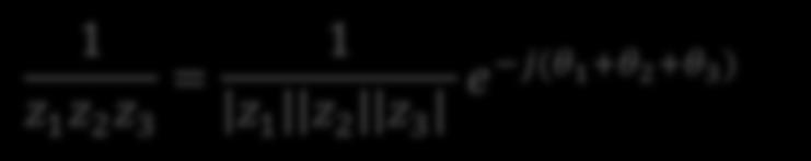
7 Complex Number Review Let z 1 = a + jb z 2 = c + jd z 3 = e + jf Then 1 = 1 z 1 a + jb = (a jb) a + jb a jb = (a jb) a 2 + b 2 = a a 2 + b 2 j b a 2 + b 2 1 z 1 = 1 z 1 θ 1 1 z 1 = 1 z 1 e jθ 1 z 1 z 2 z 3 = 1 a + jb c + jd e + jf = 1 ac bd + jbc + jad e + jf = 1 z 1 z 2 z 3 = 1 z 1 z 2 z 3 (θ 1+θ 2 + θ 3 ) 1 z 1 z 2 z 3 = 1 z 1 z 2 z 3 e j(θ 1+θ 2 +θ 3 ) 7

 (c jd ) c +")


8 Complex Number Review Let z 1 = a + jb z 2 = c + jd z 3 = e + jf Then z 1 z 2 = (a + jb) c + jd = (a + jb) (c jd ) c + jd (c jd) = z 1 z 2 = z 1 z 2 θ 1 θ 2 z 1 z 2 = z 1 z 2 e j θ 1 θ 2 z 1 n = a + jb n = a + jb 1 a + jb 2 a + jb n z = a + jb 0.32 =? z 1 n = z n nθ z = z θ z n 1 = z n j nθ 1 e z = z 0.32 j 0.32 θ 1 e 8
 = 10 log 10 P 1 /P 2 Note 10 and not 20 (that is why it is called")


9 Concepts Review The Decibel (db) Decibel is defined as ratio of two powers P 1 and P 2 Ratio (db) = 10 log 10 P 1 /P 2 Note 10 and not 20 (that is why it is called deci-bell) Consider a signal source that delivers a power P i to an amplifier. The amplifier amplifies the signal and delivers a power P L to a load. The amplifier s power gain is: G = 10 log 10 P L P i V i R i R L V L In terms of the terminal voltages and resistances: V 2 2 L R i V L R L V L R L G = 10 log 10 V 2 = 10 log 10 2 = 20 log 10 i R L V i R i V i R i P i P L In the special case when R L = R i, the power and voltage gain is G = 20 log 10 V L V i Strictly speaking, even though the 20 should be used only when R i = R L, 20 is used universally when we express voltage ratios in db, regardless of the values of R i and R L. In microelectronics, voltages and currents are normally measured and calculated for, while in RF work, quite often power is the quantity of interest. Also, in RF work, in many instances R i = R L = 50 Ω. 9

 below a sinusoidal signal source delivers 100 mw to a 50 Ω load.")
10 Concepts Review Meaning of 3-dB We often encounter phrases such as 3-dB point, 3-dB frequency, 3-dB bandwidth, half power point, etc., and there is quite a bit of confusion surrounding these terms. First, the 3 comes from the fact that log 10 2 = and 10log Thus, when an amplifier has a power gain of 2, the power gain in db will be 3 db because: P L = 2P i G = 10 log P L P i = 10 log 2 = 3 db Consider the attenuator shown Devices such as this are frequently used in RF work. The 50 Ω indicates the input impedance of the device. In (a) below a sinusoidal signal source delivers 100 mw to a 50 Ω load. In (b), the attenuator reduces the power by 3 db, which is a factor 2 so the load now dissipates 50 mw. Signal Source R L = 50 Ω Signal Source 3 db Attenuator R L = 50 Ω (a) P L = 100 mw (b) P L = 50 mw Note that the load voltage in (a) is = V RMS and in (b) the load voltage is (0.05)(50) = V RMS. While the power was reduced by a factor 2, the voltage was reduced by =

11 dbm, dbw, dbμ, etc. The decibel is related to the ratio of two powers. It is sometimes convenient to express a power relative to some reference power. One such reference is 1 mw, and this leads to the dbm: P dbm 10 log P 1 mw Example. Express the following power levels as dbm: 1 mw, 10 mw, 1 W, and 5 μw Solution 1 mw = 10 log 1 mw 1 mw = 0 dbm 10 mw = 10 log 10 mw 1 mw = 10 dbm 1 W = 10 log 1,000 mw 1 mw = 30 dbm 5 μw = 10 log = 23 dbm 11


12 dbm, dbw, dbμ, etc. dbμ 10 log P 1 μw Power, reference is 1 μw. dbm 10 log P 1 mw Power, reference is 1 mw. dbw 10 log P 1 W Power, reference is 1 W. dbv 20 log V 1 V RMS Voltage, reference is 1 V RMS regardless of impedance. dbmv 20 log dbμv 20 log dbz, dba, dbi, V 1 mv RMS Voltage, reference is 1 mv RMS across 75 Ω. Used in cable TV. V 1 μv RMS Voltage, reference is 1 μv RMS. Used in radio sensitivity, amplifier and antenna specifications. Many others, used in radar, sound, etc. 12
13 dbm, dbw, dbμ, etc. Since log A B = log A + log B it follows that we know an amplifier s gain in db, we can easily perform power level calculations. Example. An amplifier with 15 db power gain amplifies a -10 dbm signal. What is the resulting output power, expressed in dbm? Solution 10 dbm is equivalent to = 10 mw = 0.01 W. Further, 15 db gain is equivalent to a factor , so that the output power is P o = = 316 mw = W. Converting to dbm gives 10 log = 25 dbm. However, using the logarithm property log A B = log A + log B we can write directly P o = P i + G = 10 dbm + 15 = 25 dbm This works for the other db units: dbμ, dbw, etc. 13


14 dbm, dbw, dbμ, etc. If an antenna delivers V g =10 dbμv to a receiver with input an impedance of 50 Ω, what is the signal level in dbm? Solution 10 = 20log V g V RMS V g = = V RMS P = V g R 2 = = W = 10 log dbm = 97 dbm A sine wave has an amplitude of V g = 20 V. Express this as dbv. Solution The definition of dbv requires that we use the RMS value of V g. Thus: V g = 20log = 23 db 14


15 dbm, dbw, dbμ, etc. A spectrum analyzer with 50 Ω input impedance has a label next to the input warning the user to limit the input power to 10 dbm. What is maximum amplitude of a signal v t = A cos ωt that one can apply to the spectrum analyzer? Solution P 10 dbm = 10 log = 10 mw 1 P = P = A RMS 2 R = A RMS 2 A RMS = V 50 A = 2 A RMS A = 1 V 15
 What power increase (in db) does this represent? (b) Repeat but now for a 75 Ω resistor.")
 Since the same resistor is used in the calculation is used, it does not matter whether it is 50")
16 dbm, dbw, dbμ, etc. The (sine wave) voltage across a 50 Ω resistor is increased from 5 V to 7 V. (a) What power increase (in db) does this represent? (b) Repeat but now for a 75 Ω resistor. Solution Part (a) P 2 V (db) 10 log P 10 1 V = 10 log = db 52 Part (b) Since the same resistor is used in the calculation is used, it does not matter whether it is 50 Ω or 75 Ω. The values cancel and the increase in power is still db 16

17 dbm, dbw, dbμ, etc. If at a certain frequency, a cable has a loss of 5 db per 100 feet, how much power will be delivered to an antenna from a transmitter that puts out 10 W? The length of cable between transmitter and cable is 40 feet. Assume the transmitter, cable, and antenna are impedance-matched. Solution The cable attenuation is = db = 2 db This is a factor: = Thus, the power delivered is = 6.31 W Alternative Solution The cable attenuation is = db = 2 db 10 W is equivalent to 10 dbw Thus, the power delivered is 10 2 = 8 dbw = = 6.31 W 17


18 Decoupling, Coupling, Bias Tees, etc. Decoupling and bypass capacitors provide capacitors provide a reliable signal or ac ground right at the point where it is needed in a circuit while blocking dc currents from flowing. The magnitude of the reactance of decoupling and bypass capacitors reactance magnitude, i.e., 1 ωc, must be small at the working frequency and they must low inductance and ESR. A radio frequency choke (RFC) provides a short circuit to dc currents but kills (choke to death ) the ac/signal. RFCs are inductors with large reactance ωl at the working frequency. They should have low capacitance and low ESR. Decoupling Capacitor Coupling Capacitor Coupling Capacitor Equivalent ac circuit. L and C are in parallel and form a resonant circuit Varactor provides voltagevariable capacitance 18


19 Decoupling, Coupling, Bias Tees, etc. A sub-circuit that frequently appears in RF circuits is a so-called Bias T. Image from Wikipedia One branch is a short to dc but an open to RF. The other branch is a short to both dc. The last branch is a open to dc and a short to RF. Bias Tee In the circuit shown there is a bias tee as highlighted. Often one can design the bias tee into the circuit, or make one on a small board. However, because of parasitics it is often non-trivial to get a good inductor/capacitor are very high frequencies. 19


 Bias")
20 Side Bar: Bias Tee However, because of parasitics it is often non-trivial to get a good inductor/capacitor at very high frequencies, so some companies market bias tees that will do the job. Self-Made Bias Tee Commercial ($$) Bias Tee. 20


21 American Wire Gauge (AWG) AWG numbers run from 0000 to 40. In the electronics industry, odd AWG numbers are generally not used. Shown is a partial table relevant to this course. 1 mil = 1/1,000 of an inch mil = inch 21


22 AWG Thin part of IC (such as 555 timer) and an LED indicator lamp is ~0.55 mm, which corresponds to ~22 AWG diameter wire. The wire used on most solderless bread board is 22 AWG, sometimes 24. The leads on ¼ W carbon film resistor commonly used for bread boarding is 22 AWG 22


23 More on Wire The AWG refers to the conductor and does not include the insulation of the wire. Stranded wire have designations such as 7/32, 10/30, This means 7/32 7 strands, each 32 AWG 10/30 10 strands, each 30 AWG More strands means more flexible Strands 23

24 24
Radio Frequency Electronics
 Radio Frequency Electronics Preliminaries III Lee de Forest Born in Council Bluffs, Iowa in 1873 Had 180 patents Invented the vacuum tube that allows for building electronic amplifiers Vacuum tube started
Chapter 33. Alternating Current Circuits
 Chapter 33 Alternating Current Circuits 1 Capacitor Resistor + Q = C V = I R R I + + Inductance d I Vab = L dt AC power source The AC power source provides an alternative voltage, Notation - Lower case
Handout 11: AC circuit. AC generator
 Handout : AC circuit AC generator Figure compares the voltage across the directcurrent (DC) generator and that across the alternatingcurrent (AC) generator For DC generator, the voltage is constant For
ELECTROMAGNETIC OSCILLATIONS AND ALTERNATING CURRENT
 Chapter 31: ELECTROMAGNETIC OSCILLATIONS AND ALTERNATING CURRENT 1 A charged capacitor and an inductor are connected in series At time t = 0 the current is zero, but the capacitor is charged If T is the
ECE 5260 Microwave Engineering University of Virginia. Some Background: Circuit and Field Quantities and their Relations
 ECE 5260 Microwave Engineering University of Virginia Lecture 2 Review of Fundamental Circuit Concepts and Introduction to Transmission Lines Although electromagnetic field theory and Maxwell s equations
EE292: Fundamentals of ECE
 EE292: Fundamentals of ECE Fall 2012 TTh 10:00-11:15 SEB 1242 Lecture 18 121025 http://www.ee.unlv.edu/~b1morris/ee292/ 2 Outline Review RMS Values Complex Numbers Phasors Complex Impedance Circuit Analysis
1 Phasors and Alternating Currents
 Physics 4 Chapter : Alternating Current 0/5 Phasors and Alternating Currents alternating current: current that varies sinusoidally with time ac source: any device that supplies a sinusoidally varying potential
Lecture 11 - AC Power
 - AC Power 11/17/2015 Reading: Chapter 11 1 Outline Instantaneous power Complex power Average (real) power Reactive power Apparent power Maximum power transfer Power factor correction 2 Power in AC Circuits
AC Circuits Homework Set
 Problem 1. In an oscillating LC circuit in which C=4.0 μf, the maximum potential difference across the capacitor during the oscillations is 1.50 V and the maximum current through the inductor is 50.0 ma.
Driven RLC Circuits Challenge Problem Solutions
 Driven LC Circuits Challenge Problem Solutions Problem : Using the same circuit as in problem 6, only this time leaving the function generator on and driving below resonance, which in the following pairs
RLC Circuit (3) We can then write the differential equation for charge on the capacitor. The solution of this differential equation is
 We can then write the differential equation for charge on the capacitor. The solution of this differential equation is") RLC Circuit (3) We can then write the differential equation for charge on the capacitor The solution of this differential equation is (damped harmonic oscillation!), where 25 RLC Circuit (4) If we charge
RLC Circuit (3) We can then write the differential equation for charge on the capacitor The solution of this differential equation is (damped harmonic oscillation!), where 25 RLC Circuit (4) If we charge
Sinusoidal Steady-State Analysis
 Chapter 4 Sinusoidal Steady-State Analysis In this unit, we consider circuits in which the sources are sinusoidal in nature. The review section of this unit covers most of section 9.1 9.9 of the text.
Single Phase Parallel AC Circuits
 Single Phase Parallel AC Circuits 1 Single Phase Parallel A.C. Circuits (Much of this material has come from Electrical & Electronic Principles & Technology by John Bird) n parallel a.c. circuits similar
Chapter 10: Sinusoidal Steady-State Analysis
 Chapter 10: Sinusoidal Steady-State Analysis 1 Objectives : sinusoidal functions Impedance use phasors to determine the forced response of a circuit subjected to sinusoidal excitation Apply techniques
Chapter 9 Objectives
 Chapter 9 Engr8 Circuit Analysis Dr Curtis Nelson Chapter 9 Objectives Understand the concept of a phasor; Be able to transform a circuit with a sinusoidal source into the frequency domain using phasor
Electronics. Basics & Applications. group talk Daniel Biesinger
 Electronics Basics & Applications group talk 23.7.2010 by Daniel Biesinger 1 2 Contents Contents Basics Simple applications Equivalent circuit Impedance & Reactance More advanced applications - RC circuits
Alternating Current Circuits
 Alternating Current Circuits AC Circuit An AC circuit consists of a combination of circuit elements and an AC generator or source. The output of an AC generator is sinusoidal and varies with time according
15-884/484 Electric Power Systems 1: DC and AC Circuits
 15-884/484 Electric Power Systems 1: DC and AC Circuits J. Zico Kolter October 8, 2013 1 Hydro Estimated U.S. Energy Use in 2010: ~98.0 Quads Lawrence Livermore National Laboratory Solar 0.11 0.01 8.44
CHAPTER.6 :TRANSISTOR FREQUENCY RESPONSE
 CHAPTER.6 :TRANSISTOR FREQUENCY RESPONSE To understand Decibels, log scale, general frequency considerations of an amplifier. low frequency analysis - Bode plot low frequency response BJT amplifier Miller
CHAPTER 22 ELECTROMAGNETIC INDUCTION
 CHAPTER 22 ELECTROMAGNETIC INDUCTION PROBLEMS 47. REASONING AND Using Equation 22.7, we find emf 2 M I or M ( emf 2 ) t ( 0.2 V) ( 0.4 s) t I (.6 A) ( 3.4 A) 9.3 0 3 H 49. SSM REASONING AND From the results
REACTANCE. By: Enzo Paterno Date: 03/2013
 REACTANCE REACTANCE By: Enzo Paterno Date: 03/2013 5/2007 Enzo Paterno 1 RESISTANCE - R i R (t R A resistor for all practical purposes is unaffected by the frequency of the applied sinusoidal voltage or
RLC Series Circuit. We can define effective resistances for capacitors and inductors: 1 = Capacitive reactance:
 RLC Series Circuit In this exercise you will investigate the effects of changing inductance, capacitance, resistance, and frequency on an RLC series AC circuit. We can define effective resistances for
BME/ISE 3511 Bioelectronics - Test Six Course Notes Fall 2016
 BME/ISE 35 Bioelectronics - Test Six ourse Notes Fall 06 Alternating urrent apacitive & Inductive Reactance and omplex Impedance R & R ircuit Analyses (D Transients, Time onstants, Steady State) Electrical
Announcements: Today: more AC circuits
 Announcements: Today: more AC circuits I 0 I rms Current through a light bulb I 0 I rms I t = I 0 cos ωt I 0 Current through a LED I t = I 0 cos ωt Θ(cos ωt ) Theta function (is zero for a negative argument)
Physics 405/505 Digital Electronics Techniques. University of Arizona Spring 2006 Prof. Erich W. Varnes
 Physics 405/505 Digital Electronics Techniques University of Arizona Spring 2006 Prof. Erich W. Varnes Administrative Matters Contacting me I will hold office hours on Tuesday from 1-3 pm Room 420K in
Circuit Analysis-III. Circuit Analysis-II Lecture # 3 Friday 06 th April, 18
 Circuit Analysis-III Sinusoids Example #1 ü Find the amplitude, phase, period and frequency of the sinusoid: v (t ) =12cos(50t +10 ) Signal Conversion ü From sine to cosine and vice versa. ü sin (A ± B)
KH600. 1GHz, Differential Input/Output Amplifier. Features. Description. Applications. Typical Application
 KH 1GHz, Differential Input/Output Amplifier www.cadeka.com Features DC - 1GHz bandwidth Fixed 1dB (V/V) gain 1Ω (differential) inputs and outputs -7/-dBc nd/3rd HD at MHz ma output current 9V pp into
55:041 Electronic Circuits The University of Iowa Fall Final Exam
 Final Exam Name: Score Max: 135 Question 1 (1 point unless otherwise noted) a. What is the maximum theoretical efficiency for a class-b amplifier? Answer: 78% b. The abbreviation/term ESR is often encountered
EXP. NO. 3 Power on (resistive inductive & capacitive) load Series connection
 load Series connection") OBJECT: To examine the power distribution on (R, L, C) series circuit. APPARATUS 1-signal function generator 2- Oscilloscope, A.V.O meter 3- Resisters & inductor &capacitor THEORY the following form for
OBJECT: To examine the power distribution on (R, L, C) series circuit. APPARATUS 1-signal function generator 2- Oscilloscope, A.V.O meter 3- Resisters & inductor &capacitor THEORY the following form for
ECE2262 Electric Circuits. Chapter 6: Capacitance and Inductance
 ECE2262 Electric Circuits Chapter 6: Capacitance and Inductance Capacitors Inductors Capacitor and Inductor Combinations Op-Amp Integrator and Op-Amp Differentiator 1 CAPACITANCE AND INDUCTANCE Introduces
Physics 208: Electricity and Magnetism Final Exam, Secs May 2003 IMPORTANT. Read these directions carefully:
 Physics 208: Electricity and Magnetism Final Exam, Secs. 506 510 2 May 2003 Instructor: Dr. George R. Welch, 415 Engineering-Physics, 845-7737 Print your full name: Sign your name: Please fill in your
Part 4: Electromagnetism. 4.1: Induction. A. Faraday's Law. The magnetic flux through a loop of wire is
 1 Part 4: Electromagnetism 4.1: Induction A. Faraday's Law The magnetic flux through a loop of wire is Φ = BA cos θ B A B = magnetic field penetrating loop [T] A = area of loop [m 2 ] = angle between field
SINUSOIDAL STEADY STATE CIRCUIT ANALYSIS
 SINUSOIDAL STEADY STATE CIRCUIT ANALYSIS 1. Introduction A sinusoidal current has the following form: where I m is the amplitude value; ω=2 πf is the angular frequency; φ is the phase shift. i (t )=I m.sin
SCHOOL OF MATHEMATICS MATHEMATICS FOR PART I ENGINEERING. Self-paced Course
 SCHOOL OF MATHEMATICS MATHEMATICS FOR PART I ENGINEERING Self-paced Course MODULE 26 APPLICATIONS TO ELECTRICAL CIRCUITS Module Topics 1. Complex numbers and alternating currents 2. Complex impedance 3.
Homework Assignment 08
 Homework Assignment 08 Question 1 (Short Takes) Two points each unless otherwise indicated. 1. Give one phrase/sentence that describes the primary advantage of an active load. Answer: Large effective resistance
Alternating Current (AC) Circuits
 Circuits") Alternating Current (AC) Circuits We have been talking about DC circuits Constant currents and voltages Resistors Linear equations Now we introduce AC circuits Time-varying currents and voltages Resistors,
Alternating Current (AC) Circuits We have been talking about DC circuits Constant currents and voltages Resistors Linear equations Now we introduce AC circuits Time-varying currents and voltages Resistors,
Electromagnetic Oscillations and Alternating Current. 1. Electromagnetic oscillations and LC circuit 2. Alternating Current 3.
 Electromagnetic Oscillations and Alternating Current 1. Electromagnetic oscillations and LC circuit 2. Alternating Current 3. RLC circuit in AC 1 RL and RC circuits RL RC Charging Discharging I = emf R
AC Circuits III. Physics 2415 Lecture 24. Michael Fowler, UVa
 AC Circuits III Physics 415 Lecture 4 Michael Fowler, UVa Today s Topics LC circuits: analogy with mass on spring LCR circuits: damped oscillations LCR circuits with ac source: driven pendulum, resonance.
Impedance/Reactance Problems
 Impedance/Reactance Problems. Consider the circuit below. An AC sinusoidal voltage of amplitude V and frequency ω is applied to the three capacitors, each of the same capacitance C. What is the total reactance
Supplemental Notes on Complex Numbers, Complex Impedance, RLC Circuits, and Resonance
 Supplemental Notes on Complex Numbers, Complex Impedance, RLC Circuits, and Resonance Complex numbers Complex numbers are expressions of the form z = a + ib, where both a and b are real numbers, and i
Self-Inductance. Φ i. Self-induction. = (if flux Φ 1 through 1 loop. Tm Vs A A. Lecture 11-1
 Lecture - Self-Inductance As current i through coil increases, magnetic flux through itself increases. This in turn induces back emf in the coil itself When current i is decreasing, emf is induced again
EE221 Circuits II. Chapter 14 Frequency Response
 EE22 Circuits II Chapter 4 Frequency Response Frequency Response Chapter 4 4. Introduction 4.2 Transfer Function 4.3 Bode Plots 4.4 Series Resonance 4.5 Parallel Resonance 4.6 Passive Filters 4.7 Active
Physics 142 AC Circuits Page 1. AC Circuits. I ve had a perfectly lovely evening but this wasn t it. Groucho Marx
 Physics 142 A ircuits Page 1 A ircuits I ve had a perfectly lovely evening but this wasn t it. Groucho Marx Alternating current: generators and values It is relatively easy to devise a source (a generator
b) (4) How large is the current through the 2.00 Ω resistor, and in which direction?
 (4) How large is the current through the 2.00 Ω resistor, and in which direction?") General Physics II Exam 2 - Chs. 19 21 - Circuits, Magnetism, EM Induction - Sep. 29, 2016 Name Rec. Instr. Rec. Time For full credit, make your work clear. Show formulas used, essential steps, and results
General Physics II Exam 2 - Chs. 19 21 - Circuits, Magnetism, EM Induction - Sep. 29, 2016 Name Rec. Instr. Rec. Time For full credit, make your work clear. Show formulas used, essential steps, and results
I. Impedance of an R-L circuit.
 I. Impedance of an R-L circuit. [For inductor in an AC Circuit, see Chapter 31, pg. 1024] Consider the R-L circuit shown in Figure: 1. A current i(t) = I cos(ωt) is driven across the circuit using an AC
Resonant Matching Networks
 Chapter 1 Resonant Matching Networks 1.1 Introduction Frequently power from a linear source has to be transferred into a load. If the load impedance may be adjusted, the maximum power theorem states that
db: Units & Calculations
 ICTP-ITU-URSI School on Wireless Networking for Development The Abdus Salam International Centre for Theoretical Physics ICTP, Trieste (Italy), 6 to 24 February 2006 db: Units & Calculations Ryszard Struzak
EE221 Circuits II. Chapter 14 Frequency Response
 EE22 Circuits II Chapter 4 Frequency Response Frequency Response Chapter 4 4. Introduction 4.2 Transfer Function 4.3 Bode Plots 4.4 Series Resonance 4.5 Parallel Resonance 4.6 Passive Filters 4.7 Active
RP mA, Ultra-Low Noise, Ultra-Fast CMOS LDO Regulator. General Description. Features. Applications. Ordering Information. Marking Information
 RP122 3mA, Ultra-Low Noise, Ultra-Fast CMOS LDO Regulator General Description The RP122 is designed for portable RF and wireless applications with demanding performance and space requirements. The RP122
Prof. Anyes Taffard. Physics 120/220. Voltage Divider Capacitor RC circuits
 Prof. Anyes Taffard Physics 120/220 Voltage Divider Capacitor RC circuits Voltage Divider The figure is called a voltage divider. It s one of the most useful and important circuit elements we will encounter.
NAME SID EE42/100 Spring 2013 Final Exam 1
 NAME SID EE42/100 Spring 2013 Final Exam 1 1. Short answer questions a. There are approximately 36x10 50 nucleons (protons and neutrons) in the earth. If we wanted to give each one a unique n-bit address,
Lecture 05 Power in AC circuit
 CA2627 Building Science Lecture 05 Power in AC circuit Instructor: Jiayu Chen Ph.D. Announcement 1. Makeup Midterm 2. Midterm grade Grade 25 20 15 10 5 0 10 15 20 25 30 35 40 Grade Jiayu Chen, Ph.D. 2
EE221 - Practice for the Midterm Exam
 EE1 - Practice for the Midterm Exam 1. Consider this circuit and corresponding plot of the inductor current: Determine the values of L, R 1 and R : L = H, R 1 = Ω and R = Ω. Hint: Use the plot to determine
Chapter 2. Engr228 Circuit Analysis. Dr Curtis Nelson
 Chapter 2 Engr228 Circuit Analysis Dr Curtis Nelson Chapter 2 Objectives Understand symbols and behavior of the following circuit elements: Independent voltage and current sources; Dependent voltage and
Laboratory I: Impedance
 Physics 331, Fall 2008 Lab I - Handout 1 Laboratory I: Impedance Reading: Simpson Chapter 1 (if necessary) & Chapter 2 (particularly 2.9-2.13) 1 Introduction In this first lab we review the properties
Oscillations and Electromagnetic Waves. March 30, 2014 Chapter 31 1
 Oscillations and Electromagnetic Waves March 30, 2014 Chapter 31 1 Three Polarizers! Consider the case of unpolarized light with intensity I 0 incident on three polarizers! The first polarizer has a polarizing
12 Chapter Driven RLC Circuits
 hapter Driven ircuits. A Sources... -. A ircuits with a Source and One ircuit Element... -3.. Purely esistive oad... -3.. Purely Inductive oad... -6..3 Purely apacitive oad... -8.3 The Series ircuit...
12. Introduction and Chapter Objectives
 Real Analog - Circuits 1 Chapter 1: Steady-State Sinusoidal Power 1. Introduction and Chapter Objectives In this chapter we will address the issue of power transmission via sinusoidal or AC) signals. This
EE105 Fall 2014 Microelectronic Devices and Circuits
 EE05 Fall 204 Microelectronic Devices and Circuits Prof. Ming C. Wu wu@eecs.berkeley.edu 5 Sutardja Dai Hall (SDH) Terminal Gain and I/O Resistances of BJT Amplifiers Emitter (CE) Collector (CC) Base (CB)
BIOEN 302, Section 3: AC electronics
 BIOEN 3, Section 3: AC electronics For this section, you will need to have very present the basics of complex number calculus (see Section for a brief overview) and EE5 s section on phasors.. Representation
Final Exam. 55:041 Electronic Circuits. The University of Iowa. Fall 2013.
 Final Exam Name: Max: 130 Points Question 1 In the circuit shown, the op-amp is ideal, except for an input bias current I b = 1 na. Further, R F = 10K, R 1 = 100 Ω and C = 1 μf. The switch is opened at
Consider a simple RC circuit. We might like to know how much power is being supplied by the source. We probably need to find the current.
 AC power Consider a simple RC circuit We might like to know how much power is being supplied by the source We probably need to find the current R 10! R 10! is VS Vmcosωt Vm 10 V f 60 Hz V m 10 V C 150
mywbut.com Lesson 16 Solution of Current in AC Parallel and Seriesparallel
 esson 6 Solution of urrent in Parallel and Seriesparallel ircuits n the last lesson, the following points were described:. How to compute the total impedance/admittance in series/parallel circuits?. How
EE 3120 Electric Energy Systems Study Guide for Prerequisite Test Wednesday, Jan 18, pm, Room TBA
 EE 3120 Electric Energy Systems Study Guide for Prerequisite Test Wednesday, Jan 18, 2006 6-7 pm, Room TBA First retrieve your EE2110 final and other course papers and notes! The test will be closed book
2. The following diagram illustrates that voltage represents what physical dimension?
 BioE 1310 - Exam 1 2/20/2018 Answer Sheet - Correct answer is A for all questions 1. A particular voltage divider with 10 V across it consists of two resistors in series. One resistor is 7 KΩ and the other
Electric Circuit Theory
 Electric Circuit Theory Nam Ki Min nkmin@korea.ac.kr 010-9419-2320 Chapter 11 Sinusoidal Steady-State Analysis Nam Ki Min nkmin@korea.ac.kr 010-9419-2320 Contents and Objectives 3 Chapter Contents 11.1
AC Circuits. The Capacitor
 The Capacitor Two conductors in close proximity (and electrically isolated from one another) form a capacitor. An electric field is produced by charge differences between the conductors. The capacitance
Use of the decibel and the neper
 Rec. ITU-R V.574-4 1 RECOMMENDATION ITU-R V.574-4 USE OF THE DECIBEL AND THE NEPER IN TELECOMMUNICATIONS*, **, *** Rec. ITU-R V.574-4 (1978-1982-1986-1990-2000) Scope This text recommends the symbols to
11. AC Circuit Power Analysis
 . AC Circuit Power Analysis Often an integral part of circuit analysis is the determination of either power delivered or power absorbed (or both). In this chapter First, we begin by considering instantaneous
MODULE-4 RESONANCE CIRCUITS
 Introduction: MODULE-4 RESONANCE CIRCUITS Resonance is a condition in an RLC circuit in which the capacitive and inductive Reactance s are equal in magnitude, there by resulting in purely resistive impedance.
INTC 1307 Instrumentation Test Equipment Teaching Unit 6 AC Bridges
 IHLAN OLLEGE chool of Engineering & Technology ev. 0 W. lonecker ev. (8/6/0) J. Bradbury INT 307 Instrumentation Test Equipment Teaching Unit 6 A Bridges Unit 6: A Bridges OBJETIVE:. To explain the operation
Sinusoids and Phasors
 CHAPTER 9 Sinusoids and Phasors We now begins the analysis of circuits in which the voltage or current sources are time-varying. In this chapter, we are particularly interested in sinusoidally time-varying
Pulses in transmission lines
 Pulses in transmission lines Physics 401, Fall 2018 Eugene V. Colla Definition Distributed parameters network Pulses in transmission line Wave equation and wave propagation Reflections. Resistive load
Sinusoidal Steady-State Analysis
 Sinusoidal Steady-State Analysis Almost all electrical systems, whether signal or power, operate with alternating currents and voltages. We have seen that when any circuit is disturbed (switched on or
Chapter 32A AC Circuits. A PowerPoint Presentation by Paul E. Tippens, Professor of Physics Southern Polytechnic State University
 Chapter 32A AC Circuits A PowerPoint Presentation by Paul E. Tippens, Professor of Physics Southern Polytechnic State University 2007 Objectives: After completing this module, you should be able to: Describe
UNIVERSITY OF CAMBRIDGE INTERNATIONAL EXAMINATIONS General Certificate of Education Advanced Level
 UNIVERSITY OF CAMBRIDGE INTERNATIONAL EXAMINATIONS General Certificate of Education Advanced Level *3242847993* PHYSICS 9702/43 Paper 4 A2 Structured Questions October/November 2012 2 hours Candidates
Module 4. Single-phase AC circuits. Version 2 EE IIT, Kharagpur
 Module 4 Single-phase circuits ersion EE T, Kharagpur esson 6 Solution of urrent in Parallel and Seriesparallel ircuits ersion EE T, Kharagpur n the last lesson, the following points were described:. How
CIRCUIT ANALYSIS II. (AC Circuits)
") Will Moore MT & MT CIRCUIT ANALYSIS II (AC Circuits) Syllabus Complex impedance, power factor, frequency response of AC networks including Bode diagrams, second-order and resonant circuits, damping and
Will Moore MT & MT CIRCUIT ANALYSIS II (AC Circuits) Syllabus Complex impedance, power factor, frequency response of AC networks including Bode diagrams, second-order and resonant circuits, damping and
Phasor mathematics. Resources and methods for learning about these subjects (list a few here, in preparation for your research):
:") Phasor mathematics This worksheet and all related files are licensed under the Creative Commons Attribution License, version 1.0. To view a copy of this license, visit http://creativecommons.org/licenses/by/1.0/,
Phasor mathematics This worksheet and all related files are licensed under the Creative Commons Attribution License, version 1.0. To view a copy of this license, visit http://creativecommons.org/licenses/by/1.0/,
EE292: Fundamentals of ECE
 EE292: Fundamentals of ECE Fall 2012 TTh 10:00-11:15 SEB 1242 Lecture 20 121101 http://www.ee.unlv.edu/~b1morris/ee292/ 2 Outline Chapters 1-3 Circuit Analysis Techniques Chapter 10 Diodes Ideal Model
Physics 240 Fall 2005: Exam #3 Solutions. Please print your name: Please list your discussion section number: Please list your discussion instructor:
 Physics 4 Fall 5: Exam #3 Solutions Please print your name: Please list your discussion section number: Please list your discussion instructor: Form #1 Instructions 1. Fill in your name above. This will
Alternating Current. Symbol for A.C. source. A.C.
 Alternating Current Kirchoff s rules for loops and junctions may be used to analyze complicated circuits such as the one below, powered by an alternating current (A.C.) source. But the analysis can quickly
UNIVERSITY OF CALIFORNIA College of Engineering Department of Electrical Engineering and Computer Sciences
 UNIVERSITY OF CALIFORNIA College of Engineering Department of Electrical Engineering and Computer Sciences E. Alon Final EECS 240 Monday, May 19, 2008 SPRING 2008 You should write your results on the exam
M. C. Escher: Waterfall. 18/9/2015 [tsl425 1/29]
![M. C. Escher: Waterfall. 18/9/2015 [tsl425 1/29]](/thumbs/76/73138710.jpg "M. C. Escher: Waterfall. 18/9/2015 [tsl425 1/29]") M. C. Escher: Waterfall 18/9/2015 [tsl425 1/29] Direct Current Circuit Consider a wire with resistance R = ρl/a connected to a battery. Resistor rule: In the direction of I across a resistor with resistance
M. C. Escher: Waterfall 18/9/2015 [tsl425 1/29] Direct Current Circuit Consider a wire with resistance R = ρl/a connected to a battery. Resistor rule: In the direction of I across a resistor with resistance
Decibel measurements
 Decibel measurements This worksheet and all related files are licensed under the Creative Commons Attribution License, version 1.0. To view a copy of this license, visit http://creativecommons.org/licenses/by/1.0/,
Lecture 24. Impedance of AC Circuits.
 Lecture 4. Impedance of AC Circuits. Don t forget to complete course evaluations: https://sakai.rutgers.edu/portal/site/sirs Post-test. You are required to attend one of the lectures on Thursday, Dec.
Refresher course on Electrical fundamentals (Basics of A.C. Circuits) by B.M.Vyas
 by B.M.Vyas") Refresher course on Electrical fundamentals (Basics of A.C. Circuits) by B.M.Vyas A specifically designed programme for Da Afghanistan Breshna Sherkat (DABS) Afghanistan 1 Areas Covered Under this Module
Refresher course on Electrical fundamentals (Basics of A.C. Circuits) by B.M.Vyas A specifically designed programme for Da Afghanistan Breshna Sherkat (DABS) Afghanistan 1 Areas Covered Under this Module
a. Clockwise. b. Counterclockwise. c. Out of the board. d. Into the board. e. There will be no current induced in the wire
 Physics 1B Winter 2012: Final Exam For Practice Version A 1 Closed book. No work needs to be shown for multiple-choice questions. The first 10 questions are the makeup Quiz. The remaining questions are
Name (print): Lab (circle): W8 Th8 Th11 Th2 F8. θ (radians) θ (degrees) cos θ sin θ π/ /2 1/2 π/4 45 2/2 2/2 π/3 60 1/2 3/2 π/
: Lab (circle): W8 Th8 Th11 Th2 F8. θ (radians) θ (degrees) cos θ sin θ π/ /2 1/2 π/4 45 2/2 2/2 π/3 60 1/2 3/2 π/") Name (print): Lab (circle): W8 Th8 Th11 Th2 F8 Trigonometric Identities ( cos(θ) = cos(θ) sin(θ) = sin(θ) sin(θ) = cos θ π ) 2 Cosines and Sines of common angles Euler s Formula θ (radians) θ (degrees)
Name (print): Lab (circle): W8 Th8 Th11 Th2 F8 Trigonometric Identities ( cos(θ) = cos(θ) sin(θ) = sin(θ) sin(θ) = cos θ π ) 2 Cosines and Sines of common angles Euler s Formula θ (radians) θ (degrees)
E2.2 Analogue Electronics
 E2.2 Analogue Electronics Instructor : Christos Papavassiliou Office, email : EE 915, c.papavas@imperial.ac.uk Lectures : Monday 2pm, room 408 (weeks 2-11) Thursday 3pm, room 509 (weeks 4-11) Problem,
y(d) = j
 = j") Problem 2.66 A 0-Ω transmission line is to be matched to a computer terminal with Z L = ( j25) Ω by inserting an appropriate reactance in parallel with the line. If f = 800 MHz and ε r = 4, determine the
Problem 2.66 A 0-Ω transmission line is to be matched to a computer terminal with Z L = ( j25) Ω by inserting an appropriate reactance in parallel with the line. If f = 800 MHz and ε r = 4, determine the
Learnabout Electronics - AC Theory
 Learnabout Electronics - AC Theory Facts & Formulae for AC Theory www.learnabout-electronics.org Contents AC Wave Values... 2 Capacitance... 2 Charge on a Capacitor... 2 Total Capacitance... 2 Inductance...
Sinusoidal Steady State Analysis (AC Analysis) Part I
 Part I") Sinusoidal Steady State Analysis (AC Analysis) Part I Amin Electronics and Electrical Communications Engineering Department (EECE) Cairo University elc.n102.eng@gmail.com http://scholar.cu.edu.eg/refky/
Sinusoidal Steady State Analysis (AC Analysis) Part I Amin Electronics and Electrical Communications Engineering Department (EECE) Cairo University elc.n102.eng@gmail.com http://scholar.cu.edu.eg/refky/
Refinements to Incremental Transistor Model
 Refinements to Incremental Transistor Model This section presents modifications to the incremental models that account for non-ideal transistor behavior Incremental output port resistance Incremental changes
fusion production of elements in stars, 345
 I N D E X AC circuits capacitive reactance, 278 circuit frequency, 267 from wall socket, 269 fundamentals of, 267 impedance in general, 283 peak to peak voltage, 268 phase shift in RC circuit, 280-281
Frequency Response part 2 (I&N Chap 12)
") Frequency Response part 2 (I&N Chap 12) Introduction & TFs Decibel Scale & Bode Plots Resonance Scaling Filter Networks Applications/Design Frequency response; based on slides by J. Yan Slide 3.1 Example
Frequency Response part 2 (I&N Chap 12) Introduction & TFs Decibel Scale & Bode Plots Resonance Scaling Filter Networks Applications/Design Frequency response; based on slides by J. Yan Slide 3.1 Example
EE 40: Introduction to Microelectronic Circuits Spring 2008: Midterm 2
 EE 4: Introduction to Microelectronic Circuits Spring 8: Midterm Venkat Anantharam 3/9/8 Total Time Allotted : min Total Points:. This is a closed book exam. However, you are allowed to bring two pages
ELECTRO MAGNETIC INDUCTION
 ELECTRO MAGNETIC INDUCTION 1) A Circular coil is placed near a current carrying conductor. The induced current is anti clock wise when the coil is, 1. Stationary 2. Moved away from the conductor 3. Moved
Physics 115. AC: RL vs RC circuits Phase relationships RLC circuits. General Physics II. Session 33
 Session 33 Physics 115 General Physics II AC: RL vs RC circuits Phase relationships RLC circuits R. J. Wilkes Email: phy115a@u.washington.edu Home page: http://courses.washington.edu/phy115a/ 6/2/14 1
EE348L Lecture 1. EE348L Lecture 1. Complex Numbers, KCL, KVL, Impedance,Steady State Sinusoidal Analysis. Motivation
 EE348L Lecture 1 Complex Numbers, KCL, KVL, Impedance,Steady State Sinusoidal Analysis 1 EE348L Lecture 1 Motivation Example CMOS 10Gb/s amplifier Differential in,differential out, 5 stage dccoupled,broadband