Alternating Current (AC) Circuits
|
|
|
- Patricia Parks
- 6 years ago
- Views:
Transcription
1 Alternating Current (AC) Circuits We have been talking about DC circuits Constant currents and voltages Resistors Linear equations Now we introduce AC circuits Time-varying currents and voltages Resistors, capacitors, inductors (coils) Linear differential equations 73
2 Recall water analogy for Ohm s law (a) Battery (b) Resistor 74
3 Now we add a steel tank with rubber sheet (a) Battery (b) Resistor (c) Capacitor 75
4 Water enters one side of the tank and leaves the other, distending but not crossing the sheet. At first, water seems to flow through tank. How to decrease capacitance of tank? Make rubber sheet (a) smaller or (b) thicker. 76
 led Maxwell to his equations governing EM waves.")
5 Charge, like water is practically incompressible, but within a small volume (closely spaced plates) charge can enter one side and leave the other, without flowing across the space between. The apparent flow of current through space between the plates (the displacement current ) led Maxwell to his equations governing EM waves. 77
6 Basic Laws of Capacitance Capacitance C relates charge Q to voltage V C = Q V Since Q = I dt, V = 1 C I dt I = C dv dt Capacitance has units of Farads, F = 1 A sec / V + _ 78
 ( t) + RC dv C t dt t ( ) = V B 1 e t RC = V B")
7 Charging a Capacitor with Battery V B Voltage across resistor to find current ( ) = V B V ( C t) I t R Basic law of capacitor ( ) = C dv ( t) C I t dt Differential Equation yields exponential diminishing returns as cap becomes charged V C V C ( ) ( t) + RC dv C t dt t ( ) = V B 1 e t RC = V B 79


8 What determines capacitance C? Area A of the plates Distance d between the plates Permittivity ε of the dielectric between plates. C = ε A d Alignment of dipoles within dielectric between plates increases capacitor s ability to store charge (capacitance). Permittivity of a vacuum ε F m 1. 80
9 Disk (Ceramic) Capacitor Non-polarized Low leakage High breakdown voltage ~ 5pF 0.1μF Electrolytic Capacitor High leakage Polarized Low breakdown voltage ~ 0.1μF 10,000μF Types of Capacitors Supercapacitor (Electrochemical Double Layer) New. Effective spacing between plates in nanometers. Many Farads! May power cars someday. 3 digits ABC = (AB plus C zeros) 682 = 6800 pf 104 = 100,000 pf = μ 81
 adds to inertia/momentum. 82")
10 Inductor (coil) Water Analogy inductance is like inertia/momentum of water in pipe with flywheel. heavier flywheel (coil wrapped around iron core) adds to inertia/momentum. 82

11 Joseph Henry Invented insulation Permitted construction of much more powerful electromagnets. Derived mathematics for self-inductance Built early relays, used to give telegraph range Put Princeton Physics on the map 83
12 Basic Laws of Inductance Inductance L relates changes in the current to voltages induced by changes in the magnetic field produced by the current. I = 1 L V dt V = L di dt Inductance has units of Henries, H = 1 V sec / A. 84
13 What determines inductance L? Assume a solenoid (coil) Area A of the coil Number of turns N Length of the coil Permeability μ of the core L = µ N 2 A Permeability of a vacuum μ H m 1. 85
14 Energy Stored in Capacitor I = C dv dt P = VI = VC dv dt E = P dt E = C V dv E = 1 2 CV 2 86
15 Energy Stored in Caps and Coils Capacitors store potential energy in electric field E = 1 2 CV 2 independent of history Inductors store kinetic energy in magnetic field E = 1 2 L I 2 independent of history Resistors don t store energy at all! the energy is dissipated as power = V I 87
.")
16 Generating Sparks What if you suddenly try to stop a current? V = L di dt goes to - when switch is opened. use diode to shunt current, protect switch. Nothing changes instantly in Nature. Spark coil used in early radio (Titanic). Tesla patented the spark plug. 88
17 Symmetry of Electromagnetism (from an electronics component point of view) I = C dv dt V = 1 C I dt V = L di dt I = 1 L V dt Only difference is no magnetic monopole. 89
18 Inductance adds like Resistance Series L S = L 1 + L 2 Parallel L P = 1 1 L 1 +1 L 2 90
19 Capacitance adds like Conductance Series C S = 1 1 C 1 +1 C 2 Parallel C P = C 1 + C 2 91
20 Distribution of charge and voltage on multiple capacitors To find the charge in capacitors in parallel Find total effective capacitance C Total Charge will be Q Total = C Total V Same voltage will be on all caps (Kirchoff s Voltage Law) Q Total = VC Total = Q 1 + Q 2 V = V 1 = V 2 Q 1 = VC 1 Q 2 = VC 2 Q Total distributed proportional to capacitance 92
21 Distribution of charge and voltage on multiple capacitors To find the voltage on capacitors in series Find total effective capacitance C Total Charge will be Q Total = C Total V Same charge will be on all caps (Kirchoff s Current Law) Q Total = VC Total Q Total = Q 1 = Q 2 V 1 = Q 1 C 1 = Q Total C 1 = C Total C 1 V V 2 = Q 2 C 2 = Q Total C 2 = C Total C 2 Voltage distributed inversely proportional to capacitance V 93
22 Lorenz Contraction Length of object observed in relative motion to the object is shorter than the object s length 0 in its own rest frame as velocity v approaches speed of light c. What is Magnetism? = 0 1 v 2 c 2 Thus electrons in Wire 1 see Wire 2 as negatively charged and repel it: Magnetism! 94
23 AC circuit analysis uses Sinusoids 95
24 Superposition of Sinusoids Adding two sinusoids of the same frequency, no matter what their amplitudes and phases, yields a sinusoid of the same frequency. Why? Trigonometry does not have an answer. Linear systems change only phase and amplitude New frequencies do not appear. 96
25 Sinusoids are projections of a unit vector spinning around the origin. 97
26 Derivative shifts 90 to the left Taking a second derivative inverts a sinusoid. 98
27 Hooke s Law F = ma F = kd d = +, a constant Sinusoids result when a function is proportional to its own negative second derivative. Pervasive in nature: swings, flutes, guitar strings, electron orbits, light waves, sound waves 99
28 Orbit of the Moon Hook s Law in 2D velocity is perpendicular to displacement acceleration is negative of displacement 100
29 Complex numbers Cartesian and Polar forms on complex plane. Not vectors, though they add like vectors. Can multiply two together (not so with vectors). 101
30 Complex Numbers How to find r 102
31 Phasor - Polar form of Complex Number 103
32 Cartesian and Polar forms (cont ) 104
33 Complex Conjugates 105
34 Multiplying two complex numbers rotates by each other s phase and scales by each other s magnitude. 106
35 Dividing two complex numbers rotates the phase backwards and scales as the quotient of the magnitudes. 107
 rotate backwards real part imaginary part")
36 How to simplify a complex number in the denominator this was + (wrong) rotate backwards real part imaginary part 108
37 Multiplying by j rotates any complex number 90 z = a + jb z = jz = b + ja z b im z This can be recognized as multiplication by a rotation matrix, where z = jz = a + j b re a a b = a b Dot product projects point (a,b) onto rotated axes (circled). 109
38 Examples 110
39 111
40 112
41 The squiggly bracket: not an algebraic expression. y itself is real: the coordinate on the imaginary axis 113
42 Rotating by + or
43 115
44 2π, not π, is the magic number 116
45 Now make the phasor spin at ω = 2π f Note: frequency can be negative; phasor can spin backwards. 117
46 Multiplying by j shifts the phase by 90 j = e jπ 2 θ = 90 solution to Hooke s Law Just like a sinusoid: shifts 90 with each derivative. 118
47 All algebraic operations work with complex numbers What does it mean to raise something to an imaginary power? Consider case of e./0 with ω = 1 Euler s Identity 119
48 Consider e jωt Its derivative de jωt dt graphically. = jωe jωt im jωe jωt e jωt re is rotated by 90 and scaled by ω at all times. Thus it spins in a circle with velocity ω, and since e jωt = 1 when t = 0, e jωt = cosωt + jsinωt Euler s Identity 120
49 Voltages and Currents are Real 121
50 Cosine is sum of 2 phasors 122
51 Sine is difference between 2 phasors 123
52 Trigonometry Revealed 124
53 125
54 Complex Impedance - Capacitor represents orthogonal basis set 126
55 Complex Impedance - Inductor 127
56 Complex Impedance - Resistor 128
57 Impedance on the Complex Plane 129
58 Taxonomy of Impedance 130
59 Series Capacitors and Inductors Two capacitors in series: Z = 1 jωc jωc 2 = C 1 + C 2 jωc 1 C 2 = jω C C 2 Two inductors in series: Z = jωl 1 + jωl 2 = jω ( L 1 + L ) 2 131
60 Parallel Capacitors and Inductors Two capacitors in parallel: Z = 1 jωc 1 + jωc 2 = 1 ( ) jω C 1 + C 2 Two inductors in parallel: Z = jωl 1 jωl 2 = jω L 1 L 2 132
61 Same rules as DC circuits now AC sources 133
62 Impedance of a Passive Branch RC circuit 134
63 LC circuit - Resonance At resonance, impedances add to zero and cancel. Analogous to spring and weight system Energy in passed between magnetic and electric fields, as in electromagnetic wave. 135
64 Adding R to LC damps the ringing Like dragging your feet on the swing. Energy being passed from magnetic to electric field eventually dissipated by resistor as heat. 136

65 Tank Circuit permiability and permitivity around loop ^ 137
66 current is now through loop rather than around it How can impedance be infinite through the parallel LC circuit when each of the components can pass current? At the resonant frequency the currents trying to pass from the antenna to ground are shifted 90 in opposite directions and thus are 180 out of phase and cancel. No net current! This null point is an example of destructive interference, how lenses work with light (described by phasors 3D space). Flute. 138
67 Phasor Notation In BioE 1310, complex exponentials may be described unambiguously with shorthand notation re jθ "r θ " Unfortunately when applied to real voltages and currents, the same notation is widely used by engineers to mean sin or cos, peak, or RMS. Thus, A θ may mean (among other things) v( t) = A 2 sin( ωt +θ ) or v( t) = Acos( ωt +θ ) 139
68 Phasor Notation Ambiguity (cont ) This ambiguity is allowed to continue because linear systems change only magnitude and phase. Thus a given network of coils, capacitors, and resistors will cause the same relative change in v( t) = A 2 sin( ωt +θ ) as it does in v( t) = Acos( ωt +θ ) so it doesn t matter which definition of A θ they use for real signals, so long as they are consistent
69 Sample Problems with Phasor Notation Using our unambiguous definition of phasor notation, r θ = re jθ Express the following as a complex number in Cartesian form (x + jy): ( 4 45 )( 6 45 ) = = j In other words, multiply the magnitudes and add the phases. For division, divide the magnitudes and subtract the phases = 2 60 = 1 j 3 141
70 Another look at Superposition Asin( ωt) + Bcos( ωt) combine to form a sinusoid with frequency ω, and how any sum of sinusoids with frequency ω amplitude frequency phase i A cos( ωt +θ ) i i any sinusoid of frequency ω is a sinusoid with frequency ω 142
71 Example: cos(t) + sin(t), ω = 1 cos( t) sin( t) cos( t) + sin( t) = 2 cos t π 4 is sinusoid of same frequency. 143
72 Recall complex conjugate pairs of phasors cos( t) = e jt + e jt 2 sin( t) = e jt e jt 2 j e jt 2 _ e jt 2 j e jt 2 e jt 2 j (recall 1 ) j = j positive (solid) and negative (dashed) frequency. 144
73 Adding cos and sin conjugate pairs (black) sin( t) cos( t) creates single conjugate pair (gray). cos( t) + sin ( t ) = 2 cos t π 4 hypotenuse 145
74 Fourier Series Applies only to periodic signals x t Inverse Fourier Series + n= ( ) = a n e jnω 0t harmonic number fundamental frequency Fourier coefficient: stationary phasor (complex number) determines magnitude and phase of particular harmonic. Any periodic signal x (t) consists of a series of sinusoidal harmonics of a fundamental frequency. ω 0 Each harmonic with is a pair of complex conjugate phasors with positive and negative frequency. The DC harmonic has a constant value,. n 0 n = 0 146
75 The n th harmonic can also be written as a weighted sum of sin and cos at frequency nω 0, (n 0) A cos( nω t) + B sin( nω t) n 0 n 0 real coefficients creating a single sinusoid of a given phase and amplitude. (same as created by the conjugate phasors at n and n). The zero harmonic n = 0 (DC) is a cosine of zero frequency cos(0t) 147

, compared to just the fundamental 1rst harmonic sinusoid")
76 Building a square wave by adding the odd harmonics: 1, 3, 5, 7 An infinite number of harmonics are needed for a theoretical square wave. The harmonics account for the harsher tone of the square wave (buzzer), compared to just the fundamental 1rst harmonic sinusoid (flute). 148
77 Fourier Series: How to find coefficient a n Inverse Fourier Series x t a n = 1 T 0 stationary phasor for harmonic number n T 0 + n= ( ) = a n e jnω 0t Fourier Series x( t)e jnω 0t dt fundamental frequency backwards-spinning phasor. period T 0 = 2π ω 0 Periodic signal x (t) consists of phasors forming the sinusoidal harmonics of. ω 0 Backward-spinning phasor e jnω 0t spins the entire set of phasors in x(t), making the particular phasor e jnω 0t stand still. All other phasors complete revolutions integrating to
78 Fourier Transform Applies to any finite signal (not just periodic) Inverse Fourier Transform x( t) = 1 2π + Fourier Transform ( ) = x t X ω + X ( ω )e jωt dω ( )e jωt dt As before, backwards-spinning phasor makes corresponding component of x(t) stand still. Fourier coefficient a n has now become a continues function of frequency, X(ω), with phasors possible at every frequency. X(ω) is a stationary phasor for any particular ω that determines the magnitude and phase of the corresponding phasor in x(t). e jωt 150
79 The complex exponential e./0 forms an orthogonal basis set for any signal. Each phasor passes through a linear system without affecting the system s response to any other. To understand a linear system, all we need to know is what it does to e./0 This is the linear system s frequency response. A linear system can only change the phase and amplitude of a given phasor, not its frequency, by multiplying it by a stationary phasor H(ω), the frequency response of the system. 151
80 Frequency component X ω e./0 When inverse Fourier Transform builds x (t) x( t) = 1 2π + X ( ω )e jωt dω stationary phasor X ω scales the magnitude and rotates the phase of unit spinning phasor e./0. 152
81 Systems modeled as Filters We describe input and output signals as spectra X ω and Y ω, the amplitude and phase of e./0 at ω. System s transfer function H ω changes the magnitude and phase of X ω to yield Y ω by multiplication. Y ω = H ω X ω H ω = 6 / 7 / 153
82 Systems modeled as Filters H ω = 6 / 7 / Consider system with voltage divider of complex impedances. H ( ω ) = Z 1 Z 1 + Z 2 Same rule applies as with resistor voltage divider. Impedance divider changes the amplitude and phase of X ω e./0. 154
83 Example: RC High-Pass Filter H ω = 6 / 7 / H ( ω ) = R R + 1 jωc = jω RC 1+ jω RC At high frequencies, acts like a piece of wire. At low frequencies, attenuates and differentiates. H ( ω ) 1, ω >> 1 RC H ( ω ) jω RC, ω << 1 RC Key frequency is reciprocal of time constant RC. 155
84 Example: LR Low-Pass Filter H ω = 6 / 7 / H ( ω ) = R R + jωl = 1 1+ jω L R At low frequencies, acts like a piece of wire. At high frequencies, attenuates and integrates. H ( ω ) 1, ω << R L H ( ω ) R jωl, ω >> R L Key frequency is reciprocal of time constant L/R. 156
85 Example: RC Low-Pass Filter H ω = 6 / 7 / At low frequencies, acts like a piece of wire. (assuming no current at output) H ( ω ) = 1 jωc R + 1 jωc = H ( ω ) 1, ω << 1 RC 1 1+ jω RC At high frequencies, attenuates and integrates. H ( ω ) 1 jω RC, ω >> 1 RC Key frequency is reciprocal of time constant RC. 157
, db SPL (sound pressure level compared to threshold of")
86 Decibels ratio of gain (attenuation) 1 Bell = 10 db = order of magnitude in power P 1 db 10 log out 10 P in so if P in = 1 W and P out = 100 W è 20 db Since power voltage 2 V 1 db 20 log out 10 V in so if V in = 1 V and V out = 10 V è 20 db Alexander Graham Bell db are pure ratios, no units, as opposed to dbv (voltage compared to 1 V), db SPL (sound pressure level compared to threshold of hearing), etc. 158
87 Magnitude and Phase of Low-Pass Filter Recall low-pass filter: H ω = 9 9:./;< At corner (or cut-off ) frequency, ω C = 1/RC, H ( ω ) = 1 1+ j 1 j 1 j = 1 j 2 Magnitude (Gain/Attenuation) H ( ω ) = 1 j 2 H ( ω ) 3dB = 1 2 H ω Phase ( ) = arctan 1 2 H ( ω ) =
 (this one vs. f, not ω) http://www.electronics-tutorials.ws/filter/filter_2.")
88 Bode Plot of Low Pass Filter (previous slide) Simply a log/log plot of H ( ω ) and H ( ω ) (this one vs. f, not ω) 160
89 Magnitude and Phase of High-Pass Filter Recall high-pass filter: H ω =./;< 9:./;< At cut-off frequency, ω C = 1/RC, H ( ω ) = j 1+ j 1 j 1 j = 1+ j 2 Magnitude H ( ω ) = 1+ j 2 = 1 2 Phase H ( ω ) = arctan H ( ω ) 3dB H ( ω ) =
 (this one vs. f, not ω) http://www.electronics-tutorials.ws/filter/filter_2.")
90 Bode Plot of High Pass Filter (previous slide) Simply a log/log plot of H ( ω ) and H ( ω ) (this one vs. f, not ω) 162

91 Values for AC Voltage Peak V P or Max V M Peak-to Peak V PP Root Mean Square V RMS Any sinusoidal signal V(t) has all three values. Since sin 2 + cos 2 = 1, and since sin 2 and cos 2 must each have the same mean value, each must have a mean value of ½. Or put another way: cos 2 Therefore, for a sinusoid ( ωt) = V RMS = V P 2 ( ) 2 mean = ½ 1+ cos 2ωt 163
92 RMS used to compute AC Power in Resistor When V and I are in-phase (resistor), average power is defined as in DC. Energy is not stored in the resistor, but simply dissipated as heat. Power in a resistor may be computed from V P and or I P for sinusoids, or from V RMS and or I RMS for any signal. For any signal in a resistor: ( P = V RMS I RMS = V ) 2 RMS R P = 1 2 V P I P = 1 2 R because V RMS = V P 2 For sinusoids: and ( ) 2 V P = ( I ) 2 RMS R = 1 ( 2 I P ) 2 R I RMS = I P 2 164
93 AC Power in Capacitor or Inductor Since V RMS and I RMS are 90 outof-phase in capacitor or inductor, the power is 0 cos( ωt)sin( ωt) = sin( 2ωt) 2 Thus no heat is dissipated, all stored energy returned to circuit average = 0 Thus light propagates by passing energy from magnetic to electric fields without loss sin and cos have 0 correlation 165
94 iron core Transformer Extremely efficient at preserving power: V 1 I 1 V 2 I 2 Allows voltage (AC) to be changed: V 2 = N M V 1 Voltages and currents assumed to be sinusoids, generally reported as RMS Permits efficient high-voltage power transmission, with small current: thus little I 2 R energy wasted in long wires. 166


.")

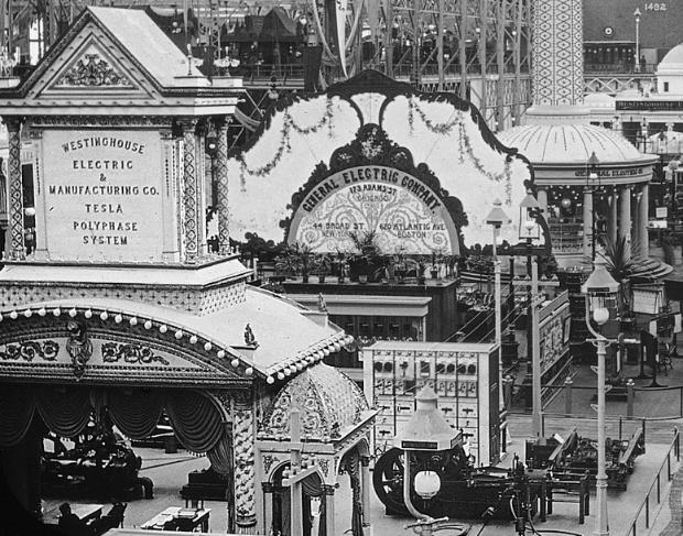
95 World s Fair Chicago 1893 Tesla and Westinghouse (AC) beat Edison (DC). George Westinghouse Nikola Tesla Thomas Edison 167
96 168
2. The following diagram illustrates that voltage represents what physical dimension?
 BioE 1310 - Exam 1 2/20/2018 Answer Sheet - Correct answer is A for all questions 1. A particular voltage divider with 10 V across it consists of two resistors in series. One resistor is 7 KΩ and the other
Sinusoids and Phasors
 CHAPTER 9 Sinusoids and Phasors We now begins the analysis of circuits in which the voltage or current sources are time-varying. In this chapter, we are particularly interested in sinusoidally time-varying
RLC Circuit (3) We can then write the differential equation for charge on the capacitor. The solution of this differential equation is
 We can then write the differential equation for charge on the capacitor. The solution of this differential equation is") RLC Circuit (3) We can then write the differential equation for charge on the capacitor The solution of this differential equation is (damped harmonic oscillation!), where 25 RLC Circuit (4) If we charge
RLC Circuit (3) We can then write the differential equation for charge on the capacitor The solution of this differential equation is (damped harmonic oscillation!), where 25 RLC Circuit (4) If we charge
Circuit Analysis-III. Circuit Analysis-II Lecture # 3 Friday 06 th April, 18
 Circuit Analysis-III Sinusoids Example #1 ü Find the amplitude, phase, period and frequency of the sinusoid: v (t ) =12cos(50t +10 ) Signal Conversion ü From sine to cosine and vice versa. ü sin (A ± B)
EE40 Lecture 11 Josh Hug 7/19/2010
 EE40 Lecture Josh 7/9/200 Logistical Things Lab 4 tomorrow Lab 5 (active filter lab) on Wednesday Prototype for future lab for EE40 Prelab is very short, sorry. Please give us our feedback Google docs
EE292: Fundamentals of ECE
 EE292: Fundamentals of ECE Fall 2012 TTh 10:00-11:15 SEB 1242 Lecture 18 121025 http://www.ee.unlv.edu/~b1morris/ee292/ 2 Outline Review RMS Values Complex Numbers Phasors Complex Impedance Circuit Analysis
Electric Circuit Theory
 Electric Circuit Theory Nam Ki Min nkmin@korea.ac.kr 010-9419-2320 Chapter 11 Sinusoidal Steady-State Analysis Nam Ki Min nkmin@korea.ac.kr 010-9419-2320 Contents and Objectives 3 Chapter Contents 11.1
Prof. Anyes Taffard. Physics 120/220. Voltage Divider Capacitor RC circuits
 Prof. Anyes Taffard Physics 120/220 Voltage Divider Capacitor RC circuits Voltage Divider The figure is called a voltage divider. It s one of the most useful and important circuit elements we will encounter.
AP Physics C Mechanics Objectives
 AP Physics C Mechanics Objectives I. KINEMATICS A. Motion in One Dimension 1. The relationships among position, velocity and acceleration a. Given a graph of position vs. time, identify or sketch a graph
EE 40: Introduction to Microelectronic Circuits Spring 2008: Midterm 2
 EE 4: Introduction to Microelectronic Circuits Spring 8: Midterm Venkat Anantharam 3/9/8 Total Time Allotted : min Total Points:. This is a closed book exam. However, you are allowed to bring two pages
Sinusoidal Steady-State Analysis
 Chapter 4 Sinusoidal Steady-State Analysis In this unit, we consider circuits in which the sources are sinusoidal in nature. The review section of this unit covers most of section 9.1 9.9 of the text.
Part 4: Electromagnetism. 4.1: Induction. A. Faraday's Law. The magnetic flux through a loop of wire is
 1 Part 4: Electromagnetism 4.1: Induction A. Faraday's Law The magnetic flux through a loop of wire is Φ = BA cos θ B A B = magnetic field penetrating loop [T] A = area of loop [m 2 ] = angle between field
R-L-C Circuits and Resonant Circuits
 P517/617 Lec4, P1 R-L-C Circuits and Resonant Circuits Consider the following RLC series circuit What's R? Simplest way to solve for is to use voltage divider equation in complex notation. X L X C in 0
Physics 405/505 Digital Electronics Techniques. University of Arizona Spring 2006 Prof. Erich W. Varnes
 Physics 405/505 Digital Electronics Techniques University of Arizona Spring 2006 Prof. Erich W. Varnes Administrative Matters Contacting me I will hold office hours on Tuesday from 1-3 pm Room 420K in
09/29/2009 Reading: Hambley Chapter 5 and Appendix A
 EE40 Lec 10 Complex Numbers and Phasors Prof. Nathan Cheung 09/29/2009 Reading: Hambley Chapter 5 and Appendix A Slide 1 OUTLINE Phasors as notation for Sinusoids Arithmetic with Complex Numbers Complex
Learnabout Electronics - AC Theory
 Learnabout Electronics - AC Theory Facts & Formulae for AC Theory www.learnabout-electronics.org Contents AC Wave Values... 2 Capacitance... 2 Charge on a Capacitor... 2 Total Capacitance... 2 Inductance...
ENGR 2405 Chapter 6. Capacitors And Inductors
 ENGR 2405 Chapter 6 Capacitors And Inductors Overview This chapter will introduce two new linear circuit elements: The capacitor The inductor Unlike resistors, these elements do not dissipate energy They
Electromagnetic Induction (Chapters 31-32)
") Electromagnetic Induction (Chapters 31-3) The laws of emf induction: Faraday s and Lenz s laws Inductance Mutual inductance M Self inductance L. Inductors Magnetic field energy Simple inductive circuits
Electromagnetic Induction (Chapters 31-3) The laws of emf induction: Faraday s and Lenz s laws Inductance Mutual inductance M Self inductance L. Inductors Magnetic field energy Simple inductive circuits
Chapter 10: Sinusoids and Phasors
 Chapter 10: Sinusoids and Phasors 1. Motivation 2. Sinusoid Features 3. Phasors 4. Phasor Relationships for Circuit Elements 5. Impedance and Admittance 6. Kirchhoff s Laws in the Frequency Domain 7. Impedance
f = 1 T 6 a.c. (Alternating Current) Circuits Most signals of interest in electronics are periodic : they repeat regularly as a function of time.
 Circuits Most signals of interest in electronics are periodic : they repeat regularly as a function of time.") Analogue Electronics (Aero).66 66 Analogue Electronics (Aero) 6.66 6 a.c. (Alternating Current) Circuits Most signals of interest in electronics are periodic : they repeat regularly as a function of time.
Analogue Electronics (Aero).66 66 Analogue Electronics (Aero) 6.66 6 a.c. (Alternating Current) Circuits Most signals of interest in electronics are periodic : they repeat regularly as a function of time.
Lectures 16 & 17 Sinusoidal Signals, Complex Numbers, Phasors, Impedance & AC Circuits. Nov. 7 & 9, 2011
 Lectures 16 & 17 Sinusoidal Signals, Complex Numbers, Phasors, Impedance & AC Circuits Nov. 7 & 9, 2011 Material from Textbook by Alexander & Sadiku and Electrical Engineering: Principles & Applications,
Basic Electronics. Introductory Lecture Course for. Technology and Instrumentation in Particle Physics Chicago, Illinois June 9-14, 2011
 Basic Electronics Introductory Lecture Course for Technology and Instrumentation in Particle Physics 2011 Chicago, Illinois June 9-14, 2011 Presented By Gary Drake Argonne National Laboratory drake@anl.gov
ECE2262 Electric Circuits. Chapter 6: Capacitance and Inductance
 ECE2262 Electric Circuits Chapter 6: Capacitance and Inductance Capacitors Inductors Capacitor and Inductor Combinations Op-Amp Integrator and Op-Amp Differentiator 1 CAPACITANCE AND INDUCTANCE Introduces
Final Exam Concept Map
 Final Exam Concept Map Rule of thumb to study for any comprehensive final exam - start with what you know - look at the quiz problems. If you did not do well on the quizzes, you should certainly learn
EE292: Fundamentals of ECE
 EE292: Fundamentals of ECE Fall 2012 TTh 10:00-11:15 SEB 1242 Lecture 20 121101 http://www.ee.unlv.edu/~b1morris/ee292/ 2 Outline Chapters 1-3 Circuit Analysis Techniques Chapter 10 Diodes Ideal Model
Frequency Response. Re ve jφ e jωt ( ) where v is the amplitude and φ is the phase of the sinusoidal signal v(t). ve jφ
 where v is the amplitude and φ is the phase of the sinusoidal signal v(t). ve jφ") 27 Frequency Response Before starting, review phasor analysis, Bode plots... Key concept: small-signal models for amplifiers are linear and therefore, cosines and sines are solutions of the linear differential
27 Frequency Response Before starting, review phasor analysis, Bode plots... Key concept: small-signal models for amplifiers are linear and therefore, cosines and sines are solutions of the linear differential
fusion production of elements in stars, 345
 I N D E X AC circuits capacitive reactance, 278 circuit frequency, 267 from wall socket, 269 fundamentals of, 267 impedance in general, 283 peak to peak voltage, 268 phase shift in RC circuit, 280-281
Driven RLC Circuits Challenge Problem Solutions
 Driven LC Circuits Challenge Problem Solutions Problem : Using the same circuit as in problem 6, only this time leaving the function generator on and driving below resonance, which in the following pairs
Lecture 4: R-L-C Circuits and Resonant Circuits
 Lecture 4: R-L-C Circuits and Resonant Circuits RLC series circuit: What's V R? Simplest way to solve for V is to use voltage divider equation in complex notation: V X L X C V R = in R R + X C + X L L
Induction_P1. 1. [1 mark]
![Induction_P1. 1. [1 mark]](/thumbs/88/115570773.jpg "Induction_P1. 1. [1 mark]") Induction_P1 1. [1 mark] Two identical circular coils are placed one below the other so that their planes are both horizontal. The top coil is connected to a cell and a switch. The switch is closed and
Induction_P1 1. [1 mark] Two identical circular coils are placed one below the other so that their planes are both horizontal. The top coil is connected to a cell and a switch. The switch is closed and
Phasors: Impedance and Circuit Anlysis. Phasors
 Phasors: Impedance and Circuit Anlysis Lecture 6, 0/07/05 OUTLINE Phasor ReCap Capacitor/Inductor Example Arithmetic with Complex Numbers Complex Impedance Circuit Analysis with Complex Impedance Phasor
AC Circuits. The Capacitor
 The Capacitor Two conductors in close proximity (and electrically isolated from one another) form a capacitor. An electric field is produced by charge differences between the conductors. The capacitance
Capacitor. Capacitor (Cont d)
") 1 2 1 Capacitor Capacitor is a passive two-terminal component storing the energy in an electric field charged by the voltage across the dielectric. Fixed Polarized Variable Capacitance is the ratio of
1 2 1 Capacitor Capacitor is a passive two-terminal component storing the energy in an electric field charged by the voltage across the dielectric. Fixed Polarized Variable Capacitance is the ratio of
Handout 11: AC circuit. AC generator
 Handout : AC circuit AC generator Figure compares the voltage across the directcurrent (DC) generator and that across the alternatingcurrent (AC) generator For DC generator, the voltage is constant For
ELECTROMAGNETIC OSCILLATIONS AND ALTERNATING CURRENT
 Chapter 31: ELECTROMAGNETIC OSCILLATIONS AND ALTERNATING CURRENT 1 A charged capacitor and an inductor are connected in series At time t = 0 the current is zero, but the capacitor is charged If T is the
Ch. 23 Electromagnetic Induction, AC Circuits, And Electrical Technologies
 Ch. 23 Electromagnetic Induction, AC Circuits, And Electrical Technologies Induced emf - Faraday s Experiment When a magnet moves toward a loop of wire, the ammeter shows the presence of a current When
EE221 Circuits II. Chapter 14 Frequency Response
 EE22 Circuits II Chapter 4 Frequency Response Frequency Response Chapter 4 4. Introduction 4.2 Transfer Function 4.3 Bode Plots 4.4 Series Resonance 4.5 Parallel Resonance 4.6 Passive Filters 4.7 Active
Basic Electronics. Introductory Lecture Course for. Technology and Instrumentation in Particle Physics Chicago, Illinois June 9-14, 2011
 Basic Electronics Introductory Lecture Course for Technology and Instrumentation in Particle Physics 2011 Chicago, Illinois June 9-14, 2011 Presented By Gary Drake Argonne National Laboratory Session 2
EE100Su08 Lecture #11 (July 21 st 2008)
") EE100Su08 Lecture #11 (July 21 st 2008) Bureaucratic Stuff Lecture videos should be up by tonight HW #2: Pick up from office hours today, will leave them in lab. REGRADE DEADLINE: Monday, July 28 th 2008,
EE100Su08 Lecture #11 (July 21 st 2008) Bureaucratic Stuff Lecture videos should be up by tonight HW #2: Pick up from office hours today, will leave them in lab. REGRADE DEADLINE: Monday, July 28 th 2008,
I. Impedance of an R-L circuit.
 I. Impedance of an R-L circuit. [For inductor in an AC Circuit, see Chapter 31, pg. 1024] Consider the R-L circuit shown in Figure: 1. A current i(t) = I cos(ωt) is driven across the circuit using an AC
MODULE I. Transient Response:
 Transient Response: MODULE I The Transient Response (also known as the Natural Response) is the way the circuit responds to energies stored in storage elements, such as capacitors and inductors. If a capacitor
Physics 1302W.400 Lecture 33 Introductory Physics for Scientists and Engineering II
 Physics 1302W.400 Lecture 33 Introductory Physics for Scientists and Engineering II In today s lecture, we will discuss generators and motors. Slide 30-1 Announcement Quiz 4 will be next week. The Final
Chapter 30. Inductance. PowerPoint Lectures for University Physics, 14th Edition Hugh D. Young and Roger A. Freedman Lectures by Jason Harlow
 Chapter 30 Inductance PowerPoint Lectures for University Physics, 14th Edition Hugh D. Young and Roger A. Freedman Lectures by Jason Harlow Learning Goals for Chapter 30 Looking forward at how a time-varying
Chapter 10: Sinusoidal Steady-State Analysis
 Chapter 10: Sinusoidal Steady-State Analysis 1 Objectives : sinusoidal functions Impedance use phasors to determine the forced response of a circuit subjected to sinusoidal excitation Apply techniques
CMPT 318: Lecture 5 Complex Exponentials, Spectrum Representation
 CMPT 318: Lecture 5 Complex Exponentials, Spectrum Representation Tamara Smyth, tamaras@cs.sfu.ca School of Computing Science, Simon Fraser University January 23, 2006 1 Exponentials The exponential is
CIRCUIT ANALYSIS II. (AC Circuits)
") Will Moore MT & MT CIRCUIT ANALYSIS II (AC Circuits) Syllabus Complex impedance, power factor, frequency response of AC networks including Bode diagrams, second-order and resonant circuits, damping and
Will Moore MT & MT CIRCUIT ANALYSIS II (AC Circuits) Syllabus Complex impedance, power factor, frequency response of AC networks including Bode diagrams, second-order and resonant circuits, damping and
Impedance/Reactance Problems
 Impedance/Reactance Problems. Consider the circuit below. An AC sinusoidal voltage of amplitude V and frequency ω is applied to the three capacitors, each of the same capacitance C. What is the total reactance
Slide 1 / 26. Inductance by Bryan Pflueger
 Slide 1 / 26 Inductance 2011 by Bryan Pflueger Slide 2 / 26 Mutual Inductance If two coils of wire are placed near each other and have a current passing through them, they will each induce an emf on one
Inductance, RL and RLC Circuits
 Inductance, RL and RLC Circuits Inductance Temporarily storage of energy by the magnetic field When the switch is closed, the current does not immediately reach its maximum value. Faraday s law of electromagnetic
Review of DC Electric Circuit. DC Electric Circuits Examples (source:
 Review of DC Electric Circuit DC Electric Circuits Examples (source: http://hyperphysics.phyastr.gsu.edu/hbase/electric/dcex.html) 1 Review - DC Electric Circuit Multisim Circuit Simulation DC Circuit
EXPERIMENT 07 TO STUDY DC RC CIRCUIT AND TRANSIENT PHENOMENA
 EXPERIMENT 07 TO STUDY DC RC CIRCUIT AND TRANSIENT PHENOMENA DISCUSSION The capacitor is a element which stores electric energy by charging the charge on it. Bear in mind that the charge on a capacitor
2.4 Models of Oscillation
 2.4 Models of Oscillation In this section we give three examples of oscillating physical systems that can be modeled by the harmonic oscillator equation. Such models are ubiquitous in physics, but are
Review of Linear Time-Invariant Network Analysis
 D1 APPENDIX D Review of Linear Time-Invariant Network Analysis Consider a network with input x(t) and output y(t) as shown in Figure D-1. If an input x 1 (t) produces an output y 1 (t), and an input x
P202 Practice Exam 2 Spring 2004 Instructor: Prof. Sinova
 P202 Practice Exam 2 Spring 2004 Instructor: Prof. Sinova Name: Date: (5)1. How many electrons flow through a battery that delivers a current of 3.0 A for 12 s? A) 4 B) 36 C) 4.8 10 15 D) 6.4 10 18 E)
Electric Circuit Theory
 Electric Circuit Theory Nam Ki Min nkmin@korea.ac.kr 010-9419-2320 Chapter 8 Natural and Step Responses of RLC Circuits Nam Ki Min nkmin@korea.ac.kr 010-9419-2320 8.1 Introduction to the Natural Response
Radio Frequency Electronics
 Radio Frequency Electronics Preliminaries III Lee de Forest Born in Council Bluffs, Iowa in 1873 Had 180 patents Invented the vacuum tube that allows for building electronic amplifiers Vacuum tube started
First and Second Order Circuits. Claudio Talarico, Gonzaga University Spring 2015
 First and Second Order Circuits Claudio Talarico, Gonzaga University Spring 2015 Capacitors and Inductors intuition: bucket of charge q = Cv i = C dv dt Resist change of voltage DC open circuit Store voltage
EE221 Circuits II. Chapter 14 Frequency Response
 EE22 Circuits II Chapter 4 Frequency Response Frequency Response Chapter 4 4. Introduction 4.2 Transfer Function 4.3 Bode Plots 4.4 Series Resonance 4.5 Parallel Resonance 4.6 Passive Filters 4.7 Active
RADIO AMATEUR EXAM GENERAL CLASS
 RAE-Lessons by 4S7VJ 1 CHAPTER- 2 RADIO AMATEUR EXAM GENERAL CLASS By 4S7VJ 2.1 Sine-wave If a magnet rotates near a coil, an alternating e.m.f. (a.c.) generates in the coil. This e.m.f. gradually increase
Electromagnetic Oscillations and Alternating Current. 1. Electromagnetic oscillations and LC circuit 2. Alternating Current 3.
 Electromagnetic Oscillations and Alternating Current 1. Electromagnetic oscillations and LC circuit 2. Alternating Current 3. RLC circuit in AC 1 RL and RC circuits RL RC Charging Discharging I = emf R
Self-inductance A time-varying current in a circuit produces an induced emf opposing the emf that initially set up the time-varying current.
 Inductance Self-inductance A time-varying current in a circuit produces an induced emf opposing the emf that initially set up the time-varying current. Basis of the electrical circuit element called an
Louisiana State University Physics 2102, Exam 3 April 2nd, 2009.
 PRINT Your Name: Instructor: Louisiana State University Physics 2102, Exam 3 April 2nd, 2009. Please be sure to PRINT your name and class instructor above. The test consists of 4 questions (multiple choice),
Alternating Current. Symbol for A.C. source. A.C.
 Alternating Current Kirchoff s rules for loops and junctions may be used to analyze complicated circuits such as the one below, powered by an alternating current (A.C.) source. But the analysis can quickly
Supplemental Notes on Complex Numbers, Complex Impedance, RLC Circuits, and Resonance
 Supplemental Notes on Complex Numbers, Complex Impedance, RLC Circuits, and Resonance Complex numbers Complex numbers are expressions of the form z = a + ib, where both a and b are real numbers, and i
Calculus Relationships in AP Physics C: Electricity and Magnetism
 C: Electricity This chapter focuses on some of the quantitative skills that are important in your C: Mechanics course. These are not all of the skills that you will learn, practice, and apply during the
Exam 3 Solutions. The induced EMF (magnitude) is given by Faraday s Law d dt dt The current is given by
 is given by Faraday s Law d dt dt The current is given by") PHY049 Spring 008 Prof. Darin Acosta Prof. Selman Hershfield April 9, 008. A metal rod is forced to move with constant velocity of 60 cm/s [or 90 cm/s] along two parallel metal rails, which are connected
PHY049 Spring 008 Prof. Darin Acosta Prof. Selman Hershfield April 9, 008. A metal rod is forced to move with constant velocity of 60 cm/s [or 90 cm/s] along two parallel metal rails, which are connected
Physics 1308 Exam 2 Summer 2015
 Physics 1308 Exam 2 Summer 2015 E2-01 2. The direction of the magnetic field in a certain region of space is determined by firing a test charge into the region with its velocity in various directions in
Sliding Conducting Bar
 Motional emf, final For equilibrium, qe = qvb or E = vb A potential difference is maintained between the ends of the conductor as long as the conductor continues to move through the uniform magnetic field
Yell if you have any questions
 Class 31: Outline Hour 1: Concept Review / Overview PRS Questions possible exam questions Hour : Sample Exam Yell if you have any questions P31 1 Exam 3 Topics Faraday s Law Self Inductance Energy Stored
Chapter 32. Inductance
 Chapter 32 Inductance Joseph Henry 1797 1878 American physicist First director of the Smithsonian Improved design of electromagnet Constructed one of the first motors Discovered self-inductance Unit of
Waves. Decibels. Chapter 21: Dimension
 Chapter 20: 20.1 The Wave Model 20.2 One Dimensional 20.3 Sinusoidal 20.4 Sound Light 20.5 Index of Refraction 20.6 Power, Intensity, Decibels 20.7 The Doppler Effect Chapter 21: 21.1 The Principle of
Electromagnetic Induction Faraday s Law Lenz s Law Self-Inductance RL Circuits Energy in a Magnetic Field Mutual Inductance
 Lesson 7 Electromagnetic Induction Faraday s Law Lenz s Law Self-Inductance RL Circuits Energy in a Magnetic Field Mutual Inductance Oscillations in an LC Circuit The RLC Circuit Alternating Current Electromagnetic
Lab 5 CAPACITORS & RC CIRCUITS
 L051 Name Date Partners Lab 5 CAPACITORS & RC CIRCUITS OBJECTIVES OVERVIEW To define capacitance and to learn to measure it with a digital multimeter. To explore how the capacitance of conducting parallel
General Physics (PHY 2140)
") General Physics (PHY 2140) Lecture 10 6/12/2007 Electricity and Magnetism Induced voltages and induction Self-Inductance RL Circuits Energy in magnetic fields AC circuits and EM waves Resistors, capacitors
General Physics (PHY 2140) Lecture 10 6/12/2007 Electricity and Magnetism Induced voltages and induction Self-Inductance RL Circuits Energy in magnetic fields AC circuits and EM waves Resistors, capacitors
Physics 2B Spring 2010: Final Version A 1 COMMENTS AND REMINDERS:
 Physics 2B Spring 2010: Final Version A 1 COMMENTS AND REMINDERS: Closed book. No work needs to be shown for multiple-choice questions. 1. A charge of +4.0 C is placed at the origin. A charge of 3.0 C
Chapter 9 Objectives
 Chapter 9 Engr8 Circuit Analysis Dr Curtis Nelson Chapter 9 Objectives Understand the concept of a phasor; Be able to transform a circuit with a sinusoidal source into the frequency domain using phasor
Maxwell s equations and EM waves. From previous Lecture Time dependent fields and Faraday s Law
 Maxwell s equations and EM waves This Lecture More on Motional EMF and Faraday s law Displacement currents Maxwell s equations EM Waves From previous Lecture Time dependent fields and Faraday s Law 1 Radar
Impedance. Reactance. Capacitors
 Impedance Ohm's law describes the relationship between current and voltage in circuits that are in equilibrium- that is, when the current and voltage are not changing. When we have a situation where the
Introduction to AC Circuits (Capacitors and Inductors)
") Introduction to AC Circuits (Capacitors and Inductors) Amin Electronics and Electrical Communications Engineering Department (EECE) Cairo University elc.n102.eng@gmail.com http://scholar.cu.edu.eg/refky/
Introduction to AC Circuits (Capacitors and Inductors) Amin Electronics and Electrical Communications Engineering Department (EECE) Cairo University elc.n102.eng@gmail.com http://scholar.cu.edu.eg/refky/
Sinusoidal Steady-State Analysis
 Sinusoidal Steady-State Analysis Almost all electrical systems, whether signal or power, operate with alternating currents and voltages. We have seen that when any circuit is disturbed (switched on or
Chapter 2 Circuit Elements
 Chapter Circuit Elements Chapter Circuit Elements.... Introduction.... Circuit Element Construction....3 Resistor....4 Inductor...4.5 Capacitor...6.6 Element Basics...8.6. Element Reciprocals...8.6. Reactance...8.6.3
Physics GRE: Electromagnetism. G. J. Loges 1. University of Rochester Dept. of Physics & Astronomy. xkcd.com/567/
 Physics GRE: Electromagnetism G. J. Loges University of Rochester Dept. of Physics & stronomy xkcd.com/567/ c Gregory Loges, 206 Contents Electrostatics 2 Magnetostatics 2 3 Method of Images 3 4 Lorentz
A capacitor is a device that stores electric charge (memory devices). A capacitor is a device that stores energy E = Q2 2C = CV 2
. A capacitor is a device that stores energy E = Q2 2C = CV 2") Capacitance: Lecture 2: Resistors and Capacitors Capacitance (C) is defined as the ratio of charge (Q) to voltage (V) on an object: C = Q/V = Coulombs/Volt = Farad Capacitance of an object depends on geometry
Capacitance: Lecture 2: Resistors and Capacitors Capacitance (C) is defined as the ratio of charge (Q) to voltage (V) on an object: C = Q/V = Coulombs/Volt = Farad Capacitance of an object depends on geometry
ECE2262 Electric Circuits. Chapter 6: Capacitance and Inductance
 ECE2262 Electric Circuits Chapter 6: Capacitance and Inductance Capacitors Inductors Capacitor and Inductor Combinations 1 CAPACITANCE AND INDUCTANCE Introduces two passive, energy storing devices: Capacitors
Physics 6b Winter 2015 Final Campagnari Section Test Form A
 Physics 6b Winter 2015 Final Campagnari Section Test Form A Fill out name and perm number on the scantron. Do not forget to bubble in the Test Form (A, B, C, or, D). At the end, only turn in the scantron.
Physics 6b Winter 2015 Final Campagnari Section Test Form D
 Physics 6b Winter 2015 Final Campagnari Section Test Form D Fill out name and perm number on the scantron. Do not forget to bubble in the Test Form (A, B, C, or, D). At the end, only turn in the scantron.
Review of 1 st Order Circuit Analysis
 ECEN 60 Circuits/Electronics Spring 007-7-07 P. Mathys Review of st Order Circuit Analysis First Order Differential Equation Consider the following circuit with input voltage v S (t) and output voltage
Physics 6B. Practice Final Solutions
 Physics 6B Practice Final Solutions . Two speakers placed 4m apart produce sound waves with frequency 45Hz. A listener is standing m in front of the left speaker. Describe the sound that he hears. Assume
Electrical Engineering Fundamentals for Non-Electrical Engineers
 Electrical Engineering Fundamentals for Non-Electrical Engineers by Brad Meyer, PE Contents Introduction... 3 Definitions... 3 Power Sources... 4 Series vs. Parallel... 9 Current Behavior at a Node...
Solutions to these tests are available online in some places (but not all explanations are good)...
...") The Physics GRE Sample test put out by ETS https://www.ets.org/s/gre/pdf/practice_book_physics.pdf OSU physics website has lots of tips, and 4 additional tests http://www.physics.ohiostate.edu/undergrad/ugs_gre.php
The Physics GRE Sample test put out by ETS https://www.ets.org/s/gre/pdf/practice_book_physics.pdf OSU physics website has lots of tips, and 4 additional tests http://www.physics.ohiostate.edu/undergrad/ugs_gre.php
Inductance, RL Circuits, LC Circuits, RLC Circuits
 Inductance, R Circuits, C Circuits, RC Circuits Inductance What happens when we close the switch? The current flows What does the current look like as a function of time? Does it look like this? I t Inductance
C R. Consider from point of view of energy! Consider the RC and LC series circuits shown:
 ircuits onsider the R and series circuits shown: ++++ ---- R ++++ ---- Suppose that the circuits are formed at t with the capacitor charged to value. There is a qualitative difference in the time development
Yell if you have any questions
 Class 36: Outline Hour 1: Concept Review / Overview PRS Questions Possible Exam Questions Hour : Sample Exam Yell if you have any questions P36-1 Before Starting All of your grades should now be posted
REACTANCE. By: Enzo Paterno Date: 03/2013
 REACTANCE REACTANCE By: Enzo Paterno Date: 03/2013 5/2007 Enzo Paterno 1 RESISTANCE - R i R (t R A resistor for all practical purposes is unaffected by the frequency of the applied sinusoidal voltage or
Circuit Analysis-II. Circuit Analysis-II Lecture # 5 Monday 23 rd April, 18
 Circuit Analysis-II Capacitors in AC Circuits Introduction ü The instantaneous capacitor current is equal to the capacitance times the instantaneous rate of change of the voltage across the capacitor.
Magnetic Induction. VIII. Magnetic Induction. 1. Dynamo Rule. A. Dynamos & Generators. B. Faraday s Law. C. Inductance. A. Dynamos & Generators
 Magnetic Induction VIII. Magnetic Induction A. Dynamos & Generators Dr. Bill Pezzaglia B. Faraday s Law C. Inductance Updated 03Aug5 Michael Faraday (79-867) 3 A. Dynamos & Generators 4 8 Creates first
Exam 3 Topics. Displacement Current Poynting Vector. Faraday s Law Self Inductance. Circuits. Energy Stored in Inductor/Magnetic Field
 Exam 3 Topics Faraday s Law Self Inductance Energy Stored in Inductor/Magnetic Field Circuits LR Circuits Undriven (R)LC Circuits Driven RLC Circuits Displacement Current Poynting Vector NO: B Materials,
Lab 5 - Capacitors and RC Circuits
 Lab 5 Capacitors and RC Circuits L51 Name Date Partners Lab 5 Capacitors and RC Circuits OBJECTIVES To define capacitance and to learn to measure it with a digital multimeter. To explore how the capacitance
Complex Numbers Review
 Complex Numbers view ference: Mary L. Boas, Mathematical Methods in the Physical Sciences Chapter 2 & 4 George Arfken, Mathematical Methods for Physicists Chapter 6 The real numbers (denoted R) are incomplete
Note 11: Alternating Current (AC) Circuits
 Circuits") Note 11: Alternating Current (AC) Circuits V R No phase difference between the voltage difference and the current and max For alternating voltage Vmax sin t, the resistor current is ir sin t. the instantaneous
Note 11: Alternating Current (AC) Circuits V R No phase difference between the voltage difference and the current and max For alternating voltage Vmax sin t, the resistor current is ir sin t. the instantaneous