Chapter 8. Screws, Fasteners, and the Design of
|
|
|
- Dana Parks
- 6 years ago
- Views:
Transcription
1 Chapter 8 Screws, Fasteners, and the Design of Nonpermanent Joints 1
2 Machine design what is it? Subset of Mechanical design which is Subset of Engineering i design which h is Subset of Design.which is Subset of the topic of Problem Solving What is a machine? a combination of resistant bodies arranged so that by their means the mechanical forces of nature can be compelled to do work accompanied by certain determinate motions.
3 Big picture Mechanics Time not a factor Statics Dynamics Change with time kinematics Kinetics motion Motion and forces
4 The Design Process Recognize need/define problem Create a solution/design Prepare model/prototype/solution t / l ti Test and evaluate Communicate design
5 Important to review the fundamentals of. Statics Dynamics Materials/material properties Mechanics of Materials Design of Mechanical Systems 1 Dynamics of Machinery
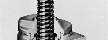
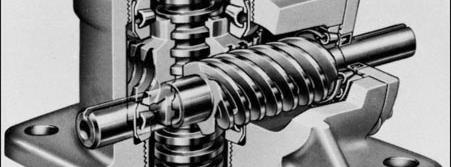
6 Power Screws Transmit angular motion to linear motion Transmit large or produce large axial force It is always desired d to reduce number of screws 6
7 Uses of Power Screws Obtain high mechanical advantage in order to move large loads with a minimum effort. e.g screw jack. Generate large forces e.g tensile testing machine, compactor press. Obtain precise axial movements e.g. camera calibration rigs.
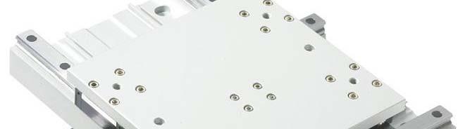
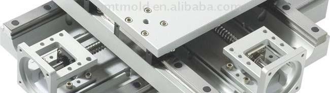
8 Applications Screw Screw Jacks Toolmakers Clamp X-Y Precision Table
9 Advantages of power screws Compact design and takes less space Large load carrying capability Simple to design and easy to manufacture Can obtain a large mechanical advantage Precise and accurate linear motion Easy maintenance Self-locking feature


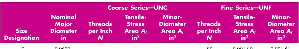
10 Thread Standards and Definitions The terminology of screw threads can be defined as the following Major diameter d, Minor diameter d r Mean dia or pitch diameter d p Lead l, distance the nut moves for one turn rotation 10
11 11
12 Single and Double threaded screws Double threaded screws s are stronger and moves faster A single-threaded screw is made by cutting a single helical groove on the cylinder. For a single thread as in our figure, the lead is the same as the pitch. A multiple-threaded product is one having two or more threads cut beside each other. A multiple-threaded screw advances a nut more rapidly than a single-threaded screw of the same pitch. Double-threaded screw has a lead equal to twice the pitch, a triplethreaded screw has a lead equal to 3 times the pitch, and so on. The thread angle is 60 o The crests of the thread may be either flat or rounded.
13 Screw Designations United National Standard UNS International Standard Organization ISO
14 UNC (Coarse thread): is the most common and recommended for ordinary applications, where the screw is threaded into a softer material. It is used for general assembly work. UNF (Fine thread): is more resistant to loosening, because of its smaller helix angle. Fine threads are widely employed in automotive, aircraft, and other applications where vibrations are likely to occur. Many tensile tests of threaded rods have shown that an unthreaded rod having a diameter equal to the mean of the pitch diameter and minor diameter will have the same tensile strength as the threaded rod. The area of this unthreaded rod is called the tensile-stress area A t of the thread rod. Metric threads are specified by writing the diameter and pitch in millimeters, in that order, thus M12X1.75 is a thread having a nominal major diameter of 12mm and pitch of 1.75mm. 14
15 Screw Designations Class of screw, defines its fit, Class 1 fits have widest tolerances, Class 2 is the most commonly used Class three for very precision application Example:1in-12 UNRF-2A-LH, A for Ext. Thread and B for Internal, R root radius Metric M10x diameter mm major diameter,1.5 pitch
16 Screw Classifications Thr read Pitch Unified National Standard UNC coarse UNF fine UNEF extra fine ISO (Metric) coarse fine Tolera ance Class 1 Class 2 Class 3 several levels fine d=0.25 Class 2 metric ¼-20 UNF 2A 20 threads/in. external threads d=12mm M12 x 1.75 p=1.75 mm/thread
17 The thread geometry of the metric M and MJ profiles 17
18 18
19 19
20 Square and Acme threads Are used for power screws Acme screw is in widespread usage. They are sometimes modified to a stub (end) form by making the thread shorter. This results in a large minor diameter and slightly stronger screw. A square thread provides somewhat greater strength and efficiency but is rarely used, due to difficulties in manufacturing the 0 o thread angle. The 5 o thread angle of the modified square thread partially overcomes this and some other objections. 20

21 Square and Acme Threads are used for the power screw

 great strength only")
22 Power Screw Types Square Acme strongest no radial load hard to manufacture 29 included angle easier to manufacture common choice for loading in both directions Buttress (contrafuerte) great strength only unidirectional loading

23 Mechanics of Power Screws 23


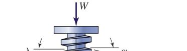
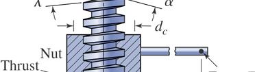
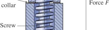
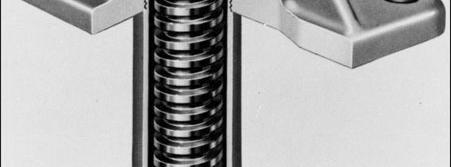
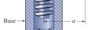
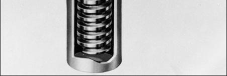
24 A square-threaded power screw with a single thread having a mean diameter dm, a pitch p, a lead angle λ, and a hli helix angle ψ is loaded dby the axial compressive force F. 24


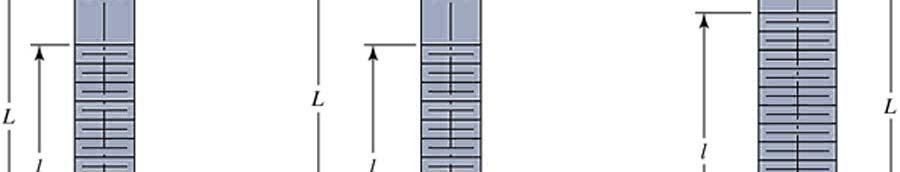
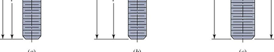
25 The torque required to raise or to lower the load: Lifting the load Lowering the load First, imagine that a single thread of the screw is unrolled for exactly a single turn The base is the circumference of the mean-thread-diameter circle and the height is the lead. 25

26 Figure (a) represents lifting the load and figure (b) represent lowering the load. The summation of all the unit axial forces acting upon the normal thread area by F To raise the load, a force P R acts to the right (Fig. a), and to lower the load, a force P L acts to the left ft(fig. b) The friction force is the product of the coefficient of friction f with the normal force N, and acts to oppose the motion 26
27 The system is in equilibrium under the action of these forces: For raising the load FH = PR N sin λ fn cos λ = 0 F = F + fn sin λ N cosλ = 0 For lowering the load V FH = PL N sin λ + fn cos λ = 0 F = F fn sin λ N cosλ = 0 V 27
28 Solve each two equations for P R and P L, we have: ( sin λ f cosλ) F + P R = cosλ f P L = sin λ ( f cosλ sin λ) F cos λ + f sin λ Divide the numerator and the denominator of these equations by cosλ and use the relation tanλ=l/πd m we then have respectively: P P R L = = F 1 F 1 [( l / πd m ) + f ] ( fl / π dm ) [ f ( l / πd m )] + ( fl / πd ) m 28
29 The torque then can be found by multiply the force by the mean radius d m /2. Therefore, T T R L = = Fd 2 m l + πfd m πd m fl Fd m πfd m l 2 πdπ d m + fl 29
30 The force and torque required to raise and lower the load : P P R L F[ ( l / πd ) ] m + f Fd = m l + πfd m T = R 1 ( fl / πd ) 2 m πd m fl F[ f ( l / πd )] Fd m m πfd m l = T = ( ) L 1+ fl / πd 2 m πd m + fl 30
31 T R is the torque required for two purposes: p to overcome thread friction and to raise the load. T L is the torque required to lower the load. This torque requires overcoming a part of the friction in lowering the load. If the lead is larger or the friction is low, the load will lower itself by causing the screw to spin without any external effort. In such cases T L is negative or zero in equation. So, if T L > 0 the screw is said to be self-locking 31
32 Condition for self-locking: This leads to Fd 2 m π fd πd m m l + fl l πd But m l tan λ = Thus f f = = π This relation states t that t self-locking l is obtained whenever the coefficient of thread friction is equal to or greater than the tangent of the thread lead angle. self-locking screw cannot turn from load F back-driving screw can be turned from load F d m tan λ > 0 32
33 Efficiency: If we let the friction equal to zero then T R reduced to: T o = o Fl 2π T Thus, the efficiency can be written as e = T R T f = 0 R = T T o R = Fl 2πT R R = Fd 2 m l + πfd m πd m fl 33


34 Acme and other threads: The normal thread load is inclined to the axis because of the thread angle 2α and the lead angle λ. Since the lead angles λ are small, this inclination can be neglected and only the effect of the thread angle α considered. See figure 8-7a. 34
35 Thus the friction term in the torque equation T R must be divided by cosα, for raising the load, or for tightening a screw or bolt, this yields Fd m l + πfd m secα T = R 2 πd m fl secα This equation is an approximate equation because λ is neglected. Acme thread is not as efficient as the square thread, because of the additional friction due to the wedging action, but it is often preferred because it is easier to machine 35
36 A third component of torque must be applied in power screw applications When it loaded axially, a thrust or collar bearing must be employed between the rotating and stationary members in order to carry the axial component. See figure 8-7b. If f c is a friction of collar friction, then T = c Ff d c c 2 For large collars, the torque should probably be computed in a manner similar to that employed for disk clutches. 36
37 Stresses in Power Screws Stresses in Threads Body Stresses Axial Torsion Thread Stresses Bearing Bending Buckling
38 Tensile Stress F F F 4F σ = = A πdπ r 2 d r
39 Torsional Stress depends on friction at screw-nut interface For screw and nut, if totally locked (rusted together), the screw experiences all of torque if frictionless, the screw experiences none of the torque Tr 16 T τ = = J π d r 3 For power screw, if low collar friction, the screw experiences nearly all of torque if high collar friction, the nut experiences most of the torque
40 Thread Stresses Bearing F σ B F = π d n p / 2 m t 2F = π d n m t p p/2 A bearing =(p/2)(πd m n t ) p/2
41 Thread Stresses Bending Fp 1 M =, I = πd r = ( p / 2),& c p / 4 F σ b Mc 6F = = I πd pn p/2 r t p/2 For both bearing and bending, F and n t are dependent on how well load is shared among teeth, therefore use F actual =0.38F and n t =1 (derived from experiments)
42 Thread Stresses Transverse shear stresses At top of tooth the transverse shear stress is zero The Von Mises σ at tthe top of fthe root t plane is found dby first identifying the orthogonal normal stresses and the shear stresses. 42
43 Mohr s Circle- Von Mises σ at the top of the root plane ' σ = σ x σ y + σ y σ z + σ z σ x + 6 τ xy + τ yz + τ 2 F ( ) ( ) ( ) ( 2 ) [ ] 0. 5 zx 6F 16T σ = τ x xy = π 3 d rnt p π dr σ y = 0 τ yz =0 4 F σ = τ z = 0 2 xz πd r p/2 p/2 z y x
44 Buckling K = radius of gyration l S R = k l I A = ( ) use d r SR ( SR ) D S > ( S ) use Euler R > R D S R D use Johnson = π 2 E S y P A CR = S y 1 E S ysr 2π 2 P CR = π 2 l EI 2
45 The engaged threads cannot share the load equally. Some experiments show that the first engaged thread carries 0.38 of the load, the second 0.25, the third 0.18, and the seventh is free of load. In estimating thread stresses by the equations above, substituting 0.38F for F and setting n t to1willgive the largest level of stresses in the thread-nut combination. 45
46 Example: 8-1 A square-thread power screw has a major diameter of 32mm and a pitch of 4mm with double threads. The given data include f = f c =0.08, 08 d c = 40mm, and df = 6.4kN per screw. Determine: 1. The thread depth, thread width, pitch diameter, minor diameter, and lead. 2. The torque required to raise and lower the load 3. The efficiency during lifting the load 4. The body stresses, torsional and compressive 5. The bearing stress 6. The thread stress bending at the root, shear at the root, and Von Mises stress 46
47 Solution 1. Thread depth= p/2=4/2=2mm Thread width=p/2=4/2=2mm 2 Pitch diameter d m =d-p/2=32-4/2=30mm Minor diameter d r =d-p=32-4=28mm 28mm Lead l=np=2(4)=8mm 47
48 Solution 2. Using equation (8-1) and (8-6), the torque required to turn the screw against the load is: T R = Fd 2 m l + π fd m + d m fl π Ff c 2 d c = = 26.18N. m Using equation (8-2) and (8-6), the load-lowering torque is: T L = Fd 2 m l πfd m + d m fl π + Ff c 2 d c = = 9.77 N. m 48
49 3. The overall efficiency in raising the load is: e = Fl 2 T π R = 6.4(8) 2π (26.18) = The body shear stress τ due to torsional moment T R at the outside of the screw body is: 16 T τ = 07MPa 3 πd = 6. r The axial nominal normal stress σ is 4F σ = π d = 2 r 10.39MPa 49
50 Solution 5. The bearing stress is, with one thread carrying 0.38F σ = 2(0.38F) π d m (1) p = B MPa 6. The thread-root bending stress σ b with one thread carrying 0.38F is Mc 6F σ b = = = MPa I πd n p r t 50
51 σ σ z x = 41.5MPa, σ y = 0, τ yz τ = zx 10.39MPa, τ = xy = 0 = 6.07MPa 0 ' σ = [( ) ( ) ] = 48.7MPa ( ) ( ) ( ) 51
52 52

53 Threaded Fasteners A standard hexagon-head bolt stress concentration occurs at the fillet & at the start of the threads Table A-29 gives the dimension for the standard hexagon-head bolt. 53
54 The diameter of the washer face is the same as the width across flats of the hexagon The threads length of metric bolts is L T 2D + 6 = 2 D D + 25 L < L 200 Ideal bolt length is one in which only one or two threads project from the nut after it is tightened. Bolt holes may have burrs and sharp edges after drilling. These could bite into the fillet and increase stress concentration. Therefore, washers must always be used under the bolt head to prevent this. Sometimes it is necessary to use washers under the nut too. L > 200 D 48 All dimensions in mm 54
55 The purpose p of a bolt is to clamp two or more parts together. The clamping load stretches or elongates the bolt; The load is obtained by twisting the nut until the bolt has elongated almost to the elastic limit. If the nut does not loosen, this bolt tension remains as preload or clamping force. 55

56 The head of a hexagon-lead cap screw 56


57 It is thinner than that of a hexagon heat bolt. Table A-30, gives the dimension for the hexagon-lead cap screw. A variety of machinescrew head styles are shown if figure
58 Several styles of hexagonal nuts are illustrated in fig And their dimensions are given in table A-28. The material of the nut is selected carefully to match that of the bolt. During tightening, the first thread of the nut tends to take the entire load, but yielding occurs, with some strengthening gdue to the cold work that takes place, and the load is eventually divided over about 3 nut threads. For this reason you should never reuse nuts; in fact, it can be dangerous to do so. 58


59 Tension Connections-The fastener Stiffness A section through a tension-loaded bolted joint is illustrated in Figure Fig
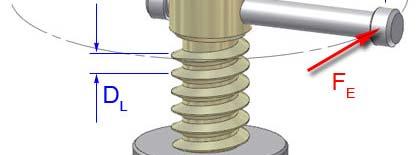
60 The purpose of the bolt is to clamp the two or more parts together. Twisting the nut stretches the bolt to produce the clamping force. This clamping force is called the Pretension or Bolt Preload. It exists in the connection after the nut has been properly tightened ed no matter whether e the external e tensile eload P is exerted or not. Since the members are being clamped together, the clamping force which produces tension in the bolt induces compression in the members. The spring constant, or stiffness constant, of an elastic member such as a bolt, is the ratio between the force applied to the member and the deflection produced by that force. Thus, The defection is defined by The spring rate k = EA l δ = Fl EA 60


61 The grip L G of a connection is the total thickness of the clamped material. In the fig 8-13, the grip is the sum of the thicknesses of both members and both washers. For Hexagon-head cap screws the effective grip is shown in figure 8-14 and is given in table 8.7 Fig
62 62
63 The stiffness of the portion of a bolt or screw within the clamped zone will generally consist of two parts: Unthreaded shank portion + threaded portion The stiffness constant of the bolt is equivalent to the stiffness of the two springs in series: 1 k = 1 k + 1 k k = k k 1 k + 2 k 63
64 Thus, spring rates of the threaded and unthreaded portions of the bolt in the clamped zone are respectively: A E t k t =, kd = lt A d l d E Where A t = tensile-stress area (table 8-1, 8-2) l t = length of threaded portion of grip A d = major-diameter area of fastener l d=length of unthreaded portion in grip 64
65 Substituting these stiffness, we get: k = b k d k l t d k + t E k t l d Where k b is the estimated effective stiffness of the bolt or cap screw in the clamped zone. For short fasteners, the one in figure 8-14 the unthreaded area is small and so the first of the expression k t is used to find k b. For long fasteners, the threaded area is relatively small, and so the second expression k d is used to find dkk b. 65
66 Joins-Member stiffness (Tension Connection-the Members) In previous section, we determined the stiffness of the fastener in the clamped zone. In this section, we will study the stiffness of the members in the clamped zone. There may be more than two members included in the grip of the teastee. fastener. Thus, Total spring rate of the member: 1 k 1 k k = 8.18 m 1 2 k i 66
67 If one of the members is a soft gasket k gasket < others members Thus, we can neglect all stiffness and only the gasket stiffness used. If there is no gasket, the stiffness of the members is rather difficult to obtain, except by experimentation, because the compression spreads out between the bolt head and the nut and hence the area is not uniform. 67

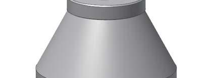
68 Some cases in which this area can be determined can be shown in Figure Ito illustrates the general cone geometry using a half-apex angle α. 68
69 The construction of an element of the cone of thickness dx subjected to a compressive force P is: Pdx d δ = EA The eaeao area of the eee element e is A = π ( 2 2 r r ) o i 2 D d = π x tanα Substituting the 2 ed equation into the 1 st and integrating the equation gives: t P dx δ = π E 0 2 [ x tan α + ( D + d ) / 2 ] [ x tan α + ( D d ) / 2 ] 2 69
70 70
71 Using a table of integrals, the spring rate or the stiffness is: k P = = δ ln πed tanα ( 2t tanα + D d )( D + d ) ( 2t tanα + D + d )( D d ) If the members of the joint have the same Young s modulus E with symmetrical frusta back to back, then they act as two identical springs in series. Thus, from equation 8-18, k m =k/2, and using the grip as l=2t and d w as the diameter of the washer face, we find the spring rate of the members to be: k m = 2ln π Ed tanα l tanα + d d ( w )( d w + d ) ( l tanα + d + d )( d d ) w w 71
72 The diameter of the washer face is about 50 percent greater than the fastener diameter for standard hexagon-head bolts and cap screws. Thus we can simplify k m equation by letting d w =1.5d and if we use α=30 o k πEd = m l d 2ln l + 2.5d 72
73 73
74 74
75 75
76 76
77 77
78 78
79 Bolt Strength: Table 8-11 list the classes and specifications of most the standard metric threaded fasteners. The proof load of a bolt is the maximum load (force) that a bolt can withstand without acquiring a permanent set. Proof strength is the quotient of the proof load and the tensile-stress area. Although proof strength and yield strength have something in common, the yield strength is usually the higher of the two because it is band on a 0.2 percent permanent df deformation. 79
80 80
81 Tension Joints-The External Load What happens when an external tensile load P is applied to a bl bolted connection? The load P is tension, and it causes the connection to stretch, or elongate, through some distance δ. It is assumed that the clamping force (the preload F i ) has been correctly applied by tightening the nut before P is applied. 81


82 To determine what portion of the externally applied load is carried by the bolt and what portion by the connected parts in the assembly, we can first draw the free body diagram: P b +F i P m -F i 82
83 The Symbols that are going to be used are: F i = preload P = external tensile load per bolt P b = portion of P taken by bolt P m = portion of P taken by members F b = P b +F i =resultant bolt load F m = P m -FF i =resultant load on members C = fraction of external load P carried by bolt 1-C C = fraction of external load P carried by members N = Number of bolts in the joint ( if N bolts equally share the total external load then P = P total / N) 83
84 Applying the condition of equilibrium for the forces P = P b + P m (1) Where P b is due to the increased bolt (tensile) force P m represents the decreased clamping (compression) force between the members 84
85 The deformation of the bolt and the members are the same and can be defined by: Pb Pm δ = and δ = (2) k b k m The compatibility condition is then: P m P = b (3) k m k b 85
86 from (1) and (3) we have: kb P Pb = = CP kb + km P = P P = ( 1 C)P m Where C=k b / (k b +k m ) is called the stiffness constant of the jit joint. b (4) 86
87 The total forces on the bolt and the members are: F F b m = = P b P m + F i F i = = CP + F i < 0 ( 1 C) P F F < 0 i F m m (5) The results are valid only as long as some clamping load remains in the members The ratios C and 1-C are the coefficients of P in equation (5). It describes the proportion of the external load taken by the bolt and by the members respectively. In all cases, the members take over %80 of the external load. Think how important this when fatigue loading is present. Making L G longer causes the members to take an even greater percentage of the external load. 87
88 Torque Requirements (Relating Bolt Torque to Bolt Tension) The most important factor determining the preload in a bolt is the torque required to tighten the bolt. The torque may be applied manually by means of a wrench that has a dial attachment indicating the magnitude of the torque being enforced. Pneumatic or air wrenches give more consistent results than a manual torque wrench and are employed extensively. 88
89 An expression relating applied torque to initial tension can be obtained using the equation developed for power screws. Observe that the load F of a screw is equivalent to F i for a bolt and that collar friction in the jack corresponds to friction on the flat surface of the nut or under the screw head. Thus Fi d m l + πfd m secα T = + 2 d m fl sec π α F i f c 2 d c (6) 89
90 Since tanλ=l/πd m, we divide the numerator and denominator of the first term by πd m and get Fi dm tan λ + f sec α Fi T = f tan sec λ α The diameter of the washer face of a hexagonal nut is the same as the width across flats and equal to 1.5 times the nominal size. Therefore the mean collar diameter is d c = (d+1.5d)/2=1.25d. Equation (7) can now be arranged to give: fc d 2 c (7) d tan λ + f sec α T = f d f tan λ secα Where K is the torque coefficient Fi d m c = KF d i (8) 90
91 The coefficient of friction depends upon the surface smoothness, accuracy, and degree of lubrication. On the average, both f and f c are about For f = f c =0.15, K=0.2, 0 2 no matter what size bolts are employed and no matter whether the threads are coarse or fine. 91
92 92
93 93
94 Statically Loaded Tension Joint with Preload Equations (5) represent the forces in a bolted joint with preload. The tensile stress σ b in the bolt can be found as: σ b = CP A t + F A i t = ( S p ) / n p (9) A means of ensuring a safe joint requires that the external load be smaller than that needed to cause the joint separate. Yielding factor of safety guarding against static stress exceeding the proof strength 94
95 Let n LP be the value of external load that would cause bolt failure and limiting value of σ b be the proof strength S p. Thus equation (9) becomes: Cn P F L i + = S (10) p A A Thus the load factor n L is: n L >1 in equation (11) σ b < S p n L t = t S p At Fi (11) CP 95
96 Another means of ensuring a safe joint is to require that the external load be smaller than that needed to cause the joint to separate. If separation does occur, then entire external load will be imposed on the bolt. Let P 0 be the value of the external load that would cause joint separation. At separation F m =0, thus from second equation in (5): ( 1 C) P0 F = 0 i (12) 96
97 Let the factor of safety against joint separation be: n 0 = P o External loads that would cause joint separation Substituting P 0 =n 0 P in equation (12) we find P 0 P (13) n 0 = P F i ( 1 C) (14) Here n 0 is a load factor guarding against joint separation and P is the maximum load applied to the joint. 97
98 The bolt strength is the main factor in the design and analysis of bolted connections. The proof load F p is the load that a bolt can carry without developing a permanent deformation. For both static and fatigue loading that the following be used for preload: 0.75Fp reused connection s F (15) i = 0.9Fp permanent connection s Where F p is the proof load, obtained from equation F = P A t S P (16) Here S p is the proof strength obtained from Tables (8-9 to 8-11). For other material, an approximate value is S P =0.85S y. 98
99 Gasketed Joints Sometimes a sealing or gasketing material must be placed between the parts connected. Gaskets are made of materials that t are soft relative to other joint parts. The gasket pressure p is found by dividing the force in the member by the gasket area per bolt (N). p F m = (17) For a load factor n, equation (11) can be written as: A g / N F m ( C) np Fi = 1 (18) 99
100 Substituting (18) into (17) gives the gasket pressure as: p N = Fi np 1 A g [ ( C )] (19) Note: to maintain the uniformity of pressure, bolts should not be spaced more than six bolt diameters apart. But to maintain wrench clearance, bolts should be spaced at least three diameters apart. So, a rough rule for bolt spacing when the bolts are arranged around a circle is (20) πd 3 b Nd Where D b is the diameter of the bolt circle and N is the number of bolts 6 100
101 Fatigue Loading Most of the time, the type of fatigue loading encountered in the analysis of bolted joints is one in which the externally applied load fluctuates between zero and some maximum force P. This would be the situation in a pressure cylinder, for example where a pressure either exists or does not exist For such cases: Thus, F max =F b and F min =F i F a =( F max - F min )/2=(F b - F i )/2 101
102 Dividing this by A t yields the alternating component of the bolt stress: F b F i ( CP + F i ) F i CP σ (21) a = = = 2A 2A 2A t The mean stress is equal to the alternating component plus the minimum stress, σ i = F i / A t t F i CP σ = m (22) 2A + A On the designer s fatigue diagram as shown in figure 8-20, the load line is: t t t σ = σ + σ m a σ i (23) 102
103 Goodman fatigue diagram The stress on the bolt starts from the preload stress and increases with a constant slope of 1. S S a m Se = S = S a ( S σ ) ut ut + S +σ i e i 103
104 The strength components S a and S m of the fatigue failure locus. Using Goodman failure criteria: S a S + m S e S ut = 1 (24) Substitute equation (23) with σ as S for into (24) we have: S S a = = S e m S a ( S σ ) S ut ut + + σ i S e i (25) In this section, K f is applied for both σ a and σ m 104
105 The factor of safety yguarding gagainst fatigue is given by n f = S σ a a or n f = ( Sut At F ) ( i S + S ) 2Se CP + When there is no preload, F i = 0, C = 1, thus n f 0 S = 2 P e ut ( S + S ) ut S ut A t e e (26) (27) 105
106 Preload is beneficial for resisting fatigue when n f / n fo is greater than unity. Thus, F i (1-C)S ut A t After solving equation of n f, you should also check the possibility of yielding using the proof strength. n p = S p (28) σ + σ m σ a 106


107 Example As shown in figure is a crosssection taken from a pressure cylinder. A total of N bolts are to be used to resist a separating force of 160 kn. The members are of No. 25 cast iron. The bolt is M16X2 class 8.8. Find: 1. The stiffnesses k b and k m 2. The stiffness constant of the joint C 3. The minimum number of bolts required using a factor of safety 2 and accounting for the fact that the bolts may be reused when the joint is taken apart. 4. What is the new bolt preload 20 mm 20 mm M16X2 class
108 Solution: 1. Finding the stiffnesses k b and k m The stiffness of the bolt k b is: From M16X2 nominal major diameter D = d = 16 mm, Pitch P = 2 mm From table A-31 with M16 H = 14.8 mm for Regular Hexagonal head. The total length of the bolt L = L G + H + (2 threads after the nuts) Thus, L = 2(20) (P) = (2) = 58.8 mm From table A-17, choose L=60 mm 108
109 From equation 8-14 or table 8-7 L T = 2D + 6 = 2(16) + 6 = 38mm l d =L-L T = = 22mm l t = L G -ll d = = 18mm From table 8-1, A t = 157 mm 2 A d = πd 2 /4 = π(16) ( ) 2 /4 = mm 2 Bolt is steel E=200GPa Therefore, the stiffness of the bolt is: Ad At E kb = = 892.6MN / A l + A l d t + t d m 109
110 From table A-24 for no. 25 cast iron we will use E =11.5 kpsi = 11.5(6.88) = MPa Hence, the stiffness of the member k m : πEd k m = = MN / m l + 0.5d 2ln l dd 110
111 2. The stiffness constant of the joint C C = k b k b + k m =
112 3. The number of bolts N From table 8-11, for property class 8.8 and M16 S p = 600MPa F p = A ts p = (157)(600) ) = 94200N For reused F i =0.75F p =0.75(94200) = 70650N Therefore: 2 S p At Fi (600)(157) n = = = N 5.6 C( P / N) (0.413)( / N) = Take N = 6 bolts n = 2.14, which is greater than the required value. So we choose six bolts use the recommended tightening preload 112
113 4. The new bolt preload For N = 6, the new bolt preload can be calculated by: ( P / N ) = N Fi = S P At nc
114 114
115 115
116 116
117 Example An M30X3.5 ISO 8.8 bolt is used in a joint at recommended preload and the joint is subject to a repeated tensile fatigue load of P=80kN per bolt. The joint constant is C=0.33. Find the load factors and the factor of safety guarding against a fatigue failure based on the Goodman theory. 117
118 Solution From table 8-1 D = d = 30 mm P=3.5 mm, A t = 561mm 2 From table 8-11 For 8.8 class and M30X3.5 S p = 600 MPa, S y = 660 MPa, S ut = 830 MPa From table 8-17 For ISO 8.8 S e =129 MPa 118
119 n S σ f F a i i S = a = = σ S F A e i t a ( S σ ) S ut ut + S e i ( S A ) = 0.75(600)(561) = = 0.75 F = 0.75 = p σ i = = 450MPa ( ) 129( ) S a = = 51.16MPa CP (0.33)(80000) σ a = = 6 2A 2(561)(10 ) n f t = = p t N 119
120 The load factor n and the factor of safety against joint separation: S n = n = p A t CP F F i (600)(561) = = 3.2 (0.33)(80000) (80000)(1 0.33) i = = 0 P(1 C)
121 121
122 122
123 123
124 124
125 125
126 Shear Joints Riveted and bolted joints loaded in sheer are treated exactly alike in design and analysis. In days when driving hot rivets was a common structural joining i method, the driving i ensured that t the rivets filled every hole completely and, upon cooling, providing a clamping preload. This kind of rivet pattern can shear a sheer load. 126
127 Bolted and Riveted Joints Loaded in Shear: In figure 9-24a is shown a riveted connection loaded in shear. There are several various means by which this connection might ihfil fail: 127
128 Failure by bending of the rivet or of the riveted members at as shown in figure 9-24-b. The bending moment is approximately M = Ft/2,, where F is the shearing force and t is the grip of the rivet, that is, the total thickness of the connected parts. σ =Mc/I 128
129 Failure of the rivet by pure shear as shown in figure 9 24-c. The shear stress can be calculated using the formula: τ = F/A. Where A is the cross-sectional area of all the rivets in the group. The diameter used in the design is the rivet diameter not the hole. 129
130 Rupture of one of the connected members or plates by pure tension. Figure 9-24-d The formula σ = F/A, where A is the net area of the plate (the area reduced dby an amount equal lto the area of all llthe rivet tholes). It is true that the use of a bolt with an initial preload and, sometimes, a rivet will place the area around the hole in compression and thus to nullify effects of stress concentration. Unless definite steps are taken to ensure that the preload does not relax, it s on the conservative side to design as if the full stressconcentration effect were presented. 130
131 Failure occurs by crushing of the rivet or plate as shown in fig 9-24-e It is usually called a bearing stress The formula can be calculated using the formula, σ = F/A, where: A = projected area for a single rivet is (t)(d) t = the thickness of the thinnest plate. d = the rivet or bolt diameter. 131
132 Failure due to edge shearing, or tearing as shown in fig f and g. In structure practice this failure is avoided by spacing the rivets at least 1 ½ diameters away from the edge. 132
133 In structure design it is customary to select in advance the number of rivets and their diameters and spacing. The strength is then determined for each method of failure. Ifth the calculated ltdstrength this not satisfactory, tif t a change is made in the diameter, spacing, or number of rivets used to bring the strength in line with expected loading conditions. 133
134 134
135 135
136 136
137 137
138 138
139 Centroids of bolt groups In figure 8.23 let A 1 to A 5 be the respective cross-sectional areas of a groups of five pins, or hot-driven rivets, or tightfiltering shoulder bolts. 139
140 Under this assumption the rotational pivot point lies at the centroid of the cross-sectional area pattern of the pins, rivets, or bolts. Ui Using static, tti the centroid idgg can be found dby: x 5 A x 5 i i 1 1 = and y = A A i A i 1 i y i (8-49) 140
141 Shear of bolts and rivets due to eccentric loading An example of eccentric loading of fasteners is shown in figure 8-24 The beam is fastened to vertical numbers at the ends with specially prepared load-sharing bolts. The centers of the bolts at the left end of the beam are drawn to a large scale in figure (8-24-c). 141

142 Point 0 represents the centroid of the group. The result at forces acting on the pins with a net force and moment equal and opposite to the reaction loads V 1 and M 1 acting at
143 The total load taken by each bolt can be found by the following 3 steps 1. Each bolt takes F = V 1 / n, Where 1, n = number of bolts in the group. F = direct load or primary shear. 2. The moment load or secondary shear: It is the additional load on each bolt due to the moment M. If r A, r B, r C, etc, are the radial distances from the centroid to the center of each bolt. Thus, M Where F is the moment load " " " = F Ar A + F Br B + F C r C +... (1) 143
144 Therefore (2) C B A r F r F r F " " " = = Solving equations (2) and (2) simultaneously, we obtain: C B A r r r M (8.50) " = C B A n n r r r M r F Where n refers to the particular bolt whose load is to be found 3 Find the resultant load of both vertical and moment loads 3. Find the resultant load of both vertical and moment loads 144
145 Example As shown in figure a 15X200 mm rectangular steel bar cantilevered to a 250 mm steel channel using four bolts. On the basis of the external load of 16kN, find: a) The resultant load on each bolt b) The maximum bolt shear stress c) The maximum bearing stress d) The bending stress through bolts A and B. 145
146 M16X2 bolts F=16kN C D O B A
147 Solution By symmetric, the location of the centroid is located at point O. The free body diagram shows that the shear reaction V would pass through O and the moment reaction M would be about O. 147
148 V=16kN and M = (16)(0.425) = 6.8kN.m The distance from the centroid to the center of each bolt is r = ((60) 2 + (75) 2 ) 0.5 = 96mm The primary shear load per bolt is F `=V/n = 16/4 = 4kN Since the distance between the bolts are equal, hence the secondary shear forces can be calculated using equation 8-50: " Mr M 6800 F1 = = = = kN r 4r ( ) The primary and secondary shear forces are plotted also in the pervious figure. 148
149 a) The result load on each bolt can be found using the parallelogram rule Therefore, the resultant load on each bolts are: F A = F B =21.0 kn F C = F D =13.8 kn 149
150 b) The maximum Load on each bolt Bolts A and B carries the largest shear load, therefore our calculation will be for bolts A and B Where the shear acts on the bolt? To answer this question, we need to find first the length of the bolt: L=L G + H + 2P L G = = 25mm H: From table A-31, H=14.8mm, P = 2 L = (15+10) + (14.8) + 2(2) = 43.8 mm From table A-17, L= 45mm 150
151 From equation 8-14, L T = 2D+6 = 2(16)+6 = 38mm the unthreaded length l d = L- L T = 45-38=7mm the threaded length l t =L G -l d =25-7=18mm You can see now that the unthreaded length is less than the thickness of the plate (15 thickness). Therefore the shear stress area is based on the threaded section and hence will be represented by the miner diameter for the bolt: from table 8-1, A r =144mm 2. τ =F/A r = 21000/144(10-6) = MPa 151
152 c) The maximum bearing stress: From the figure we can see that the channel is thinner than the bar, so the largest bearing stress is due to the pressing of the bolt against the channel web: F FA σ b = = = = MPa A b td (10)(16) ) 152
153 d) The bending stress through bolts A and B. M = 16( ) = 5600N. m I = I bar 2 ( 2 I d A) holes (200) 15(16) (60) (15)(16) ) Mc 5600(100) σ = = = 67.8MPa 6 I 8.26(10 ) = = 8.26(10 6 ) mm 4 153
154 Keys and Pins Keys and pins are used on shafts to secure rotating elements, such as gears, pulleys, or other wheels. Keys are used to enable the transmission of torque from the shaft to the shaft-support element. Pins are used for axial positioning and for the transfer of torque or thrust or both. 154

 Squre key; (b)")
 Round pins;")
 Split tubular")
155 Figure 8-28 shows a variety of keys and pins. (a) Squre key; (b) Round key; (c) and (d) Round pins; (e) Taper pin; ;(f) Split tubular spring gpin 155
CHAPTER 8 SCREWS, FASTENERS, NONPERMANENT JOINTS
 CHAPTER 8 SCREWS, FASTENERS, NONPERMANENT JOINTS This chapter deals with the design and analysis of nonpermanent fasteners such as bolts, power screws, cap screws, setscrews, eys and pins. 8- Standards
Chapter 8. Lecture Notes Dr. Rakhmad Arief Siregar Kolej Universiti Kejuruteraan Utara Malaysia
 Chapter 8 Screw, Fasteners and the Design of Nonperanent Joint Lecture Notes Dr. Rakhad Arief Siregar Kolej Universiti Kejuruteraan Utara Malaysia Mechanical Engineering Design Sixth Metric Edition J.E.
MEMS Project 2 Assignment. Design of a Shaft to Transmit Torque Between Two Pulleys
 MEMS 029 Project 2 Assignment Design of a Shaft to Transmit Torque Between Two Pulleys Date: February 5, 206 Instructor: Dr. Stephen Ludwick Product Definition Shafts are incredibly important in order
Failure from static loading
 Failure from static loading Topics Quiz /1/07 Failures from static loading Reading Chapter 5 Homework HW 3 due /1 HW 4 due /8 What is Failure? Failure any change in a machine part which makes it unable
Arberi Ferraj. Wentworth Institute of Technology. Design of Machine Elements MECH 420
 P a g e 1 Arberi Ferraj Wentworth Institute of Technology Design of Machine Elements MECH 420 P a g e 2 1. Executive Summary A scissor car jack was designed and must be reverse-engineered in order to discover
Mechanics of Materials Primer
 Mechanics of Materials rimer Notation: A = area (net = with holes, bearing = in contact, etc...) b = total width of material at a horizontal section d = diameter of a hole D = symbol for diameter E = modulus
March 24, Chapter 4. Deflection and Stiffness. Dr. Mohammad Suliman Abuhaiba, PE
 Chapter 4 Deflection and Stiffness 1 2 Chapter Outline Spring Rates Tension, Compression, and Torsion Deflection Due to Bending Beam Deflection Methods Beam Deflections by Superposition Strain Energy Castigliano
Members Subjected to Torsional Loads
 Members Subjected to Torsional Loads Torsion of circular shafts Definition of Torsion: Consider a shaft rigidly clamped at one end and twisted at the other end by a torque T = F.d applied in a plane perpendicular
Chapter 8 Structural Design and Analysis. Strength and stiffness 5 types of load: Tension Compression Shear Bending Torsion
 Chapter 8 Structural Design and Analysis 1 Strength and stiffness 5 types of load: Tension Compression Shear Bending Torsion Normal Stress Stress is a state when a material is loaded. For normal forces
SOLUTION (17.3) Known: A simply supported steel shaft is connected to an electric motor with a flexible coupling.
 Known: A simply supported steel shaft is connected to an electric motor with a flexible coupling.") SOLUTION (17.3) Known: A simply supported steel shaft is connected to an electric motor with a flexible coupling. Find: Determine the value of the critical speed of rotation for the shaft. Schematic and
SOLUTION (17.3) Known: A simply supported steel shaft is connected to an electric motor with a flexible coupling. Find: Determine the value of the critical speed of rotation for the shaft. Schematic and
2014 MECHANICS OF MATERIALS
 R10 SET - 1 II. Tech I Semester Regular Examinations, March 2014 MEHNIS OF MTERILS (ivil Engineering) Time: 3 hours Max. Marks: 75 nswer any FIVE Questions ll Questions carry Equal Marks ~~~~~~~~~~~~~~~~~~~~~~~~~
Stress Analysis Lecture 3 ME 276 Spring Dr./ Ahmed Mohamed Nagib Elmekawy
 Stress Analysis Lecture 3 ME 276 Spring 2017-2018 Dr./ Ahmed Mohamed Nagib Elmekawy Axial Stress 2 Beam under the action of two tensile forces 3 Beam under the action of two tensile forces 4 Shear Stress
Tuesday, February 11, Chapter 3. Load and Stress Analysis. Dr. Mohammad Suliman Abuhaiba, PE
 1 Chapter 3 Load and Stress Analysis 2 Chapter Outline Equilibrium & Free-Body Diagrams Shear Force and Bending Moments in Beams Singularity Functions Stress Cartesian Stress Components Mohr s Circle for
Downloaded from Downloaded from / 1
 PURWANCHAL UNIVERSITY III SEMESTER FINAL EXAMINATION-2002 LEVEL : B. E. (Civil) SUBJECT: BEG256CI, Strength of Material Full Marks: 80 TIME: 03:00 hrs Pass marks: 32 Candidates are required to give their
COURSE TITLE : APPLIED MECHANICS & STRENGTH OF MATERIALS COURSE CODE : 4017 COURSE CATEGORY : A PERIODS/WEEK : 6 PERIODS/ SEMESTER : 108 CREDITS : 5
 COURSE TITLE : APPLIED MECHANICS & STRENGTH OF MATERIALS COURSE CODE : 4017 COURSE CATEGORY : A PERIODS/WEEK : 6 PERIODS/ SEMESTER : 108 CREDITS : 5 TIME SCHEDULE MODULE TOPICS PERIODS 1 Simple stresses
D e s i g n o f R i v e t e d J o i n t s, C o t t e r & K n u c k l e J o i n t s
 D e s i g n o f R i v e t e d J o i n t s, C o t t e r & K n u c k l e J o i n t s 1. Design of various types of riveted joints under different static loading conditions, eccentrically loaded riveted joints.
Design against fluctuating load
 Design against fluctuating load In many applications, the force acting on the spring is not constants but varies in magnitude with time. The valve springs of automotive engine subjected to millions of
STRESS. Bar. ! Stress. ! Average Normal Stress in an Axially Loaded. ! Average Shear Stress. ! Allowable Stress. ! Design of Simple Connections
 STRESS! Stress Evisdom! verage Normal Stress in an xially Loaded ar! verage Shear Stress! llowable Stress! Design of Simple onnections 1 Equilibrium of a Deformable ody ody Force w F R x w(s). D s y Support
PES Institute of Technology
 PES Institute of Technology Bangalore south campus, Bangalore-5460100 Department of Mechanical Engineering Faculty name : Madhu M Date: 29/06/2012 SEM : 3 rd A SEC Subject : MECHANICS OF MATERIALS Subject
Mechanical Design. Design of Shaft
 Mechanical Design Design of Shaft Outline Practical information Shaft design Definition of shaft? It is a rotating member, in general, has a circular cross-section and is used to transmit power. The shaft
Chapter 4 Deflection and Stiffness
 Chapter 4 Deflection and Stiffness Asst. Prof. Dr. Supakit Rooppakhun Chapter Outline Deflection and Stiffness 4-1 Spring Rates 4-2 Tension, Compression, and Torsion 4-3 Deflection Due to Bending 4-4 Beam
Determine the resultant internal loadings acting on the cross section at C of the beam shown in Fig. 1 4a.
 E X M P L E 1.1 Determine the resultant internal loadings acting on the cross section at of the beam shown in Fig. 1 a. 70 N/m m 6 m Fig. 1 Support Reactions. This problem can be solved in the most direct
: APPLIED MECHANICS & STRENGTH OF MATERIALS COURSE CODE : 4021 COURSE CATEGORY : A PERIODS/ WEEK : 5 PERIODS/ SEMESTER : 75 CREDIT : 5 TIME SCHEDULE
 COURSE TITLE : APPLIED MECHANICS & STRENGTH OF MATERIALS COURSE CODE : 4021 COURSE CATEGORY : A PERIODS/ WEEK : 5 PERIODS/ SEMESTER : 75 CREDIT : 5 TIME SCHEDULE MODULE TOPIC PERIODS 1 Simple stresses
R13. II B. Tech I Semester Regular Examinations, Jan MECHANICS OF SOLIDS (Com. to ME, AME, AE, MTE) PART-A
 PART-A") SET - 1 II B. Tech I Semester Regular Examinations, Jan - 2015 MECHANICS OF SOLIDS (Com. to ME, AME, AE, MTE) Time: 3 hours Max. Marks: 70 Note: 1. Question Paper consists of two parts (Part-A and Part-B)
SET - 1 II B. Tech I Semester Regular Examinations, Jan - 2015 MECHANICS OF SOLIDS (Com. to ME, AME, AE, MTE) Time: 3 hours Max. Marks: 70 Note: 1. Question Paper consists of two parts (Part-A and Part-B)
Review Lecture. AE1108-II: Aerospace Mechanics of Materials. Dr. Calvin Rans Dr. Sofia Teixeira De Freitas
 Review Lecture AE1108-II: Aerospace Mechanics of Materials Dr. Calvin Rans Dr. Sofia Teixeira De Freitas Aerospace Structures & Materials Faculty of Aerospace Engineering Analysis of an Engineering System
Table of Contents. Preface...xvii. Part 1. Level
 Preface...xvii Part 1. Level 1... 1 Chapter 1. The Basics of Linear Elastic Behavior... 3 1.1. Cohesion forces... 4 1.2. The notion of stress... 6 1.2.1. Definition... 6 1.2.2. Graphical representation...
PERIYAR CENTENARY POLYTECHNIC COLLEGE PERIYAR NAGAR - VALLAM THANJAVUR. DEPARTMENT OF MECHANICAL ENGINEERING QUESTION BANK
 PERIYAR CENTENARY POLYTECHNIC COLLEGE PERIYAR NAGAR - VALLAM - 613 403 - THANJAVUR. DEPARTMENT OF MECHANICAL ENGINEERING QUESTION BANK Sub : Strength of Materials Year / Sem: II / III Sub Code : MEB 310
Sample Questions for the ME328 Machine Design Final Examination Closed notes, closed book, no calculator.
 Sample Questions for the ME328 Machine Design Final Examination Closed notes, closed book, no calculator. The following is from the first page of the examination. I recommend you read it before the exam.
DESIGN AND APPLICATION
 III. 3.1 INTRODUCTION. From the foregoing sections on contact theory and material properties we can make a list of what properties an ideal contact material would possess. (1) High electrical conductivity
QUESTION BANK SEMESTER: III SUBJECT NAME: MECHANICS OF SOLIDS
 QUESTION BANK SEMESTER: III SUBJECT NAME: MECHANICS OF SOLIDS UNIT 1- STRESS AND STRAIN PART A (2 Marks) 1. Define longitudinal strain and lateral strain. 2. State Hooke s law. 3. Define modular ratio,
Engineering Mechanics: Statics
 Engineering Mechanics: Statics Chapter 6B: Applications of Friction in Machines Wedges Used to produce small position adjustments of a body or to apply large forces When sliding is impending, the resultant
Engineering Mechanics: Statics
 Engineering Mechanics: Statics Chapter 6B: Applications of Friction in Machines Wedges Used to produce small position adjustments of a body or to apply large forces When sliding is impending, the resultant
UNIT-I STRESS, STRAIN. 1. A Member A B C D is subjected to loading as shown in fig determine the total elongation. Take E= 2 x10 5 N/mm 2
 UNIT-I STRESS, STRAIN 1. A Member A B C D is subjected to loading as shown in fig determine the total elongation. Take E= 2 x10 5 N/mm 2 Young s modulus E= 2 x10 5 N/mm 2 Area1=900mm 2 Area2=400mm 2 Area3=625mm
D : SOLID MECHANICS. Q. 1 Q. 9 carry one mark each.
 GTE 2016 Q. 1 Q. 9 carry one mark each. D : SOLID MECHNICS Q.1 single degree of freedom vibrating system has mass of 5 kg, stiffness of 500 N/m and damping coefficient of 100 N-s/m. To make the system
Matlab Sheet 2. Arrays
 Matlab Sheet 2 Arrays 1. a. Create the vector x having 50 logarithmically spaced values starting at 10 and ending at 1000. b. Create the vector x having 20 logarithmically spaced values starting at 10
SRI CHANDRASEKHARENDRA SARASWATHI VISWA MAHAVIDHYALAYA
 SRI CHANDRASEKHARENDRA SARASWATHI VISWA MAHAVIDHYALAYA (Declared as Deemed-to-be University under Section 3 of the UGC Act, 1956, Vide notification No.F.9.9/92-U-3 dated 26 th May 1993 of the Govt. of
FME461 Engineering Design II
 FME461 Engineering Design II Dr.Hussein Jama Hussein.jama@uobi.ac.ke Office 414 Lecture: Mon 8am -10am Tutorial Tue 3pm - 5pm 10/1/2013 1 Semester outline Date Week Topics Reference Reading 9 th Sept 1
Unit 21 Couples and Resultants with Couples
 Unit 21 Couples and Resultants with Couples Page 21-1 Couples A couple is defined as (21-5) Moment of Couple The coplanar forces F 1 and F 2 make up a couple and the coordinate axes are chosen so that
[5] Stress and Strain
![[5] Stress and Strain](/thumbs/95/123344550.jpg "[5] Stress and Strain") [5] Stress and Strain Page 1 of 34 [5] Stress and Strain [5.1] Internal Stress of Solids [5.2] Design of Simple Connections (will not be covered in class) [5.3] Deformation and Strain [5.4] Hooke s Law
[5] Stress and Strain Page 1 of 34 [5] Stress and Strain [5.1] Internal Stress of Solids [5.2] Design of Simple Connections (will not be covered in class) [5.3] Deformation and Strain [5.4] Hooke s Law
ME Final Exam. PROBLEM NO. 4 Part A (2 points max.) M (x) y. z (neutral axis) beam cross-sec+on. 20 kip ft. 0.2 ft. 10 ft. 0.1 ft.
 M (x) y. z (neutral axis) beam cross-sec+on. 20 kip ft. 0.2 ft. 10 ft. 0.1 ft.") ME 323 - Final Exam Name December 15, 2015 Instructor (circle) PROEM NO. 4 Part A (2 points max.) Krousgrill 11:30AM-12:20PM Ghosh 2:30-3:20PM Gonzalez 12:30-1:20PM Zhao 4:30-5:20PM M (x) y 20 kip ft 0.2
ME 323 - Final Exam Name December 15, 2015 Instructor (circle) PROEM NO. 4 Part A (2 points max.) Krousgrill 11:30AM-12:20PM Ghosh 2:30-3:20PM Gonzalez 12:30-1:20PM Zhao 4:30-5:20PM M (x) y 20 kip ft 0.2
Accordingly, the nominal section strength [resistance] for initiation of yielding is calculated by using Equation C-C3.1.
![Accordingly, the nominal section strength [resistance] for initiation of yielding is calculated by using Equation C-C3.1.](/thumbs/89/98617066.jpg "Accordingly, the nominal section strength [resistance] for initiation of yielding is calculated by using Equation C-C3.1.") C3 Flexural Members C3.1 Bending The nominal flexural strength [moment resistance], Mn, shall be the smallest of the values calculated for the limit states of yielding, lateral-torsional buckling and distortional
C3 Flexural Members C3.1 Bending The nominal flexural strength [moment resistance], Mn, shall be the smallest of the values calculated for the limit states of yielding, lateral-torsional buckling and distortional
Shafts. Fig.(4.1) Dr. Salah Gasim Ahmed YIC 1
 Dr. Salah Gasim Ahmed YIC 1") Shafts. Power transmission shafting Continuous mechanical power is usually transmitted along and etween rotating shafts. The transfer etween shafts is accomplished y gears, elts, chains or other similar
Shafts. Power transmission shafting Continuous mechanical power is usually transmitted along and etween rotating shafts. The transfer etween shafts is accomplished y gears, elts, chains or other similar
Levers. 558 A Textbook of Machine Design
 558 A Textbook of Machine Design C H A P T E R 15 Levers 1. Introduction.. Application of Levers in Engineering Practice.. Design of a Lever. 4. Hand Lever. 5. Foot Lever. 6. Cranked Lever. 7. Lever for
MECE 3321 MECHANICS OF SOLIDS CHAPTER 1
 MECE 3321 MECHANICS O SOLIDS CHAPTER 1 Samantha Ramirez, MSE WHAT IS MECHANICS O MATERIALS? Rigid Bodies Statics Dynamics Mechanics Deformable Bodies Solids/Mech. Of Materials luids 1 WHAT IS MECHANICS
ENG1001 Engineering Design 1
 ENG1001 Engineering Design 1 Structure & Loads Determine forces that act on structures causing it to deform, bend, and stretch Forces push/pull on objects Structures are loaded by: > Dead loads permanent
Springs Lecture 3. Extension Springs
 Springs Lecture 3 Extension Springs Carry tensile loading Extension springs Max. Normal stress at A due to Bending and Axial loading σ A K A 6D 4 F K A + 3 πd πd 4C 4C C ( C ) r d C Max. torsional stress
4. SHAFTS. A shaft is an element used to transmit power and torque, and it can support
 4. SHAFTS A shaft is an element used to transmit power and torque, and it can support reverse bending (fatigue). Most shafts have circular cross sections, either solid or tubular. The difference between
12/25/ :27 PM. Chapter 14. Spur and Helical Gears. Mohammad Suliman Abuhaiba, Ph.D., PE
 Chapter 14 Spur and Helical Gears 1 2 The Lewis Bending Equation Equation to estimate bending stress in gear teeth in which tooth form entered into the formulation: 3 The Lewis Bending Equation Assume
Comb resonator design (2)
") Lecture 6: Comb resonator design () -Intro Intro. to Mechanics of Materials School of Electrical l Engineering i and Computer Science, Seoul National University Nano/Micro Systems & Controls Laboratory
Lecture 6: Comb resonator design () -Intro Intro. to Mechanics of Materials School of Electrical l Engineering i and Computer Science, Seoul National University Nano/Micro Systems & Controls Laboratory
D : SOLID MECHANICS. Q. 1 Q. 9 carry one mark each. Q.1 Find the force (in kn) in the member BH of the truss shown.
 in the member BH of the truss shown.") D : SOLID MECHANICS Q. 1 Q. 9 carry one mark each. Q.1 Find the force (in kn) in the member BH of the truss shown. Q.2 Consider the forces of magnitude F acting on the sides of the regular hexagon having
D : SOLID MECHANICS Q. 1 Q. 9 carry one mark each. Q.1 Find the force (in kn) in the member BH of the truss shown. Q.2 Consider the forces of magnitude F acting on the sides of the regular hexagon having
NAME: Given Formulae: Law of Cosines: Law of Sines:
 NME: Given Formulae: Law of Cosines: EXM 3 PST PROBLEMS (LESSONS 21 TO 28) 100 points Thursday, November 16, 2017, 7pm to 9:30, Room 200 You are allowed to use a calculator and drawing equipment, only.
2. Polar moment of inertia As stated above, the polar second moment of area, J is defined as. Sample copy
 GATE PATHSHALA - 91. Polar moment of inertia As stated above, the polar second moment of area, is defined as z π r dr 0 R r π R π D For a solid shaft π (6) QP 0 π d Solid shaft π d Hollow shaft, " ( do
Shared on QualifyGate.com
 GTE 014 Brief nalysis (Based on student test experiences in the stream of ME on 16th February, 014 - Second Session) Section wise analysis of the paper 1 Mark Marks Total No of Questions Engineering Mathematics
EDEXCEL NATIONAL CERTIFICATE/DIPLOMA SCIENCE FOR TECHNICIANS OUTCOME 1 - STATIC AND DYNAMIC FORCES TUTORIAL 3 STRESS AND STRAIN
 EDEXCEL NATIONAL CERTIFICATE/DIPLOMA SCIENCE FOR TECHNICIANS OUTCOME 1 - STATIC AND DYNAMIC FORCES TUTORIAL 3 STRESS AND STRAIN 1 Static and dynamic forces Forces: definitions of: matter, mass, weight,
QUESTION BANK DEPARTMENT: CIVIL SEMESTER: III SUBJECT CODE: CE2201 SUBJECT NAME: MECHANICS OF SOLIDS UNIT 1- STRESS AND STRAIN PART A
 DEPARTMENT: CIVIL SUBJECT CODE: CE2201 QUESTION BANK SEMESTER: III SUBJECT NAME: MECHANICS OF SOLIDS UNIT 1- STRESS AND STRAIN PART A (2 Marks) 1. Define longitudinal strain and lateral strain. 2. State
two structural analysis (statics & mechanics) APPLIED ACHITECTURAL STRUCTURES: DR. ANNE NICHOLS SPRING 2017 lecture STRUCTURAL ANALYSIS AND SYSTEMS
 APPLIED ACHITECTURAL STRUCTURES: DR. ANNE NICHOLS SPRING 2017 lecture STRUCTURAL ANALYSIS AND SYSTEMS") APPLIED ACHITECTURAL STRUCTURES: STRUCTURAL ANALYSIS AND SYSTEMS DR. ANNE NICHOLS SPRING 2017 lecture two structural analysis (statics & mechanics) Analysis 1 Structural Requirements strength serviceability
APPLIED ACHITECTURAL STRUCTURES: STRUCTURAL ANALYSIS AND SYSTEMS DR. ANNE NICHOLS SPRING 2017 lecture two structural analysis (statics & mechanics) Analysis 1 Structural Requirements strength serviceability
Engineering Science OUTCOME 1 - TUTORIAL 4 COLUMNS
 Unit 2: Unit code: QCF Level: Credit value: 15 Engineering Science L/601/10 OUTCOME 1 - TUTORIAL COLUMNS 1. Be able to determine the behavioural characteristics of elements of static engineering systems
Overview. Dry Friction Wedges Flatbelts Screws Bearings Rolling Resistance
 Friction Chapter 8 Overview Dry Friction Wedges Flatbelts Screws Bearings Rolling Resistance Dry Friction Friction is defined as a force of resistance acting on a body which prevents slipping of the body
Direct and Shear Stress
 Direct and Shear Stress 1 Direct & Shear Stress When a body is pulled by a tensile force or crushed by a compressive force, the loading is said to be direct. Direct stresses are also found to arise when
5. STRESS CONCENTRATIONS. and strains in shafts apply only to solid and hollow circular shafts while they are in the
 5. STRESS CONCENTRATIONS So far in this thesis, most of the formulas we have seen to calculate the stresses and strains in shafts apply only to solid and hollow circular shafts while they are in the elastic
SECOND ENGINEER REG. III/2 APPLIED MECHANICS
 SECOND ENGINEER REG. III/2 APPLIED MECHANICS LIST OF TOPICS Static s Friction Kinematics Dynamics Machines Strength of Materials Hydrostatics Hydrodynamics A STATICS 1 Solves problems involving forces
Stress Transformation Equations: u = +135 (Fig. a) s x = 80 MPa s y = 0 t xy = 45 MPa. we obtain, cos u + t xy sin 2u. s x = s x + s y.
 s x = 80 MPa s y = 0 t xy = 45 MPa. we obtain, cos u + t xy sin 2u. s x = s x + s y.") 014 Pearson Education, Inc., Upper Saddle River, NJ. All rights reserved. This material is protected under all copyright laws as they currently 9 7. Determine the normal stress and shear stress acting
014 Pearson Education, Inc., Upper Saddle River, NJ. All rights reserved. This material is protected under all copyright laws as they currently 9 7. Determine the normal stress and shear stress acting
Samantha Ramirez, MSE. Stress. The intensity of the internal force acting on a specific plane (area) passing through a point. F 2
 passing through a point. F 2") Samantha Ramirez, MSE Stress The intensity of the internal force acting on a specific plane (area) passing through a point. Δ ΔA Δ z Δ 1 2 ΔA Δ x Δ y ΔA is an infinitesimal size area with a uniform force
Samantha Ramirez, MSE Stress The intensity of the internal force acting on a specific plane (area) passing through a point. Δ ΔA Δ z Δ 1 2 ΔA Δ x Δ y ΔA is an infinitesimal size area with a uniform force
The basic dynamic load rating C is a statistical number and it is based on 90% of the bearings surviving 50 km of travel carrying the full load.
 Technical data Load Rating & Life Under normal conditions, the linear rail system can be damaged by metal fatigue as the result of repeated stress. The repeated stress causes flaking of the raceways and
MECHANICS OF MATERIALS. Prepared by Engr. John Paul Timola
 MECHANICS OF MATERIALS Prepared by Engr. John Paul Timola Mechanics of materials branch of mechanics that studies the internal effects of stress and strain in a solid body. stress is associated with the
Helical Gears n A Textbook of Machine Design
 1066 n A Textbook of Machine Design C H A P T E R 9 Helical Gears 1. Introduction.. Terms used in Helical Gears. 3. Face Width of Helical Gears. 4. Formative or Equivalent Number of Teeth for Helical Gears.
Chapter 3. Load and Stress Analysis. Lecture Slides
 Lecture Slides Chapter 3 Load and Stress Analysis 2015 by McGraw Hill Education. This is proprietary material solely for authorized instructor use. Not authorized for sale or distribution in any manner.
STATICS. Friction VECTOR MECHANICS FOR ENGINEERS: Eighth Edition CHAPTER. Ferdinand P. Beer E. Russell Johnston, Jr.
 Eighth E 8 Friction CHAPTER VECTOR MECHANICS FOR ENGINEERS: STATICS Ferdinand P. Beer E. Russell Johnston, Jr. Lecture Notes: J. Walt Oler Texas Tech University Contents Introduction Laws of Dry Friction.
Application nr. 7 (Connections) Strength of bolted connections to EN (Eurocode 3, Part 1.8)
 Strength of bolted connections to EN (Eurocode 3, Part 1.8)") Application nr. 7 (Connections) Strength of bolted connections to EN 1993-1-8 (Eurocode 3, Part 1.8) PART 1: Bolted shear connection (Category A bearing type, to EN1993-1-8) Structural element Tension
Application nr. 7 (Connections) Strength of bolted connections to EN 1993-1-8 (Eurocode 3, Part 1.8) PART 1: Bolted shear connection (Category A bearing type, to EN1993-1-8) Structural element Tension
Initial Stress Calculations
 Initial Stress Calculations The following are the initial hand stress calculations conducted during the early stages of the design process. Therefore, some of the material properties as well as dimensions
CE6306 STRENGTH OF MATERIALS TWO MARK QUESTIONS WITH ANSWERS ACADEMIC YEAR
 CE6306 STRENGTH OF MATERIALS TWO MARK QUESTIONS WITH ANSWERS ACADEMIC YEAR 2014-2015 UNIT - 1 STRESS, STRAIN AND DEFORMATION OF SOLIDS PART- A 1. Define tensile stress and tensile strain. The stress induced
(Refer Slide Time: 2:43-03:02)
") Strength of Materials Prof. S. K. Bhattacharyya Department of Civil Engineering Indian Institute of Technology, Kharagpur Lecture - 34 Combined Stresses I Welcome to the first lesson of the eighth module
Strength of Materials Prof. S. K. Bhattacharyya Department of Civil Engineering Indian Institute of Technology, Kharagpur Lecture - 34 Combined Stresses I Welcome to the first lesson of the eighth module
Design of Beams (Unit - 8)
") Design of Beams (Unit - 8) Contents Introduction Beam types Lateral stability of beams Factors affecting lateral stability Behaviour of simple and built - up beams in bending (Without vertical stiffeners)
Design of Beams (Unit - 8) Contents Introduction Beam types Lateral stability of beams Factors affecting lateral stability Behaviour of simple and built - up beams in bending (Without vertical stiffeners)
Torsion of shafts with circular symmetry
 orsion of shafts with circular symmetry Introduction Consider a uniform bar which is subject to a torque, eg through the action of two forces F separated by distance d, hence Fd orsion is the resultant
2012 MECHANICS OF SOLIDS
 R10 SET - 1 II B.Tech II Semester, Regular Examinations, April 2012 MECHANICS OF SOLIDS (Com. to ME, AME, MM) Time: 3 hours Max. Marks: 75 Answer any FIVE Questions All Questions carry Equal Marks ~~~~~~~~~~~~~~~~~~~~~~
FOUR-POINT CONTACT SLEWING RINGS - without gear [ O ]
![FOUR-POINT CONTACT SLEWING RINGS - without gear [ O ]](/thumbs/96/126795264.jpg "FOUR-POINT CONTACT SLEWING RINGS - without gear [ O ]") FOUR-POINT CONTACT SLEWING RINGS - without gear [ O ] Number of the Loading Boundary Dimensions Static Ax.Basic Load Rating Designation Weight Abutment Dimensions Curve d D T C oa G J 1 J 2 N 1 N 2 n 1
FOUR-POINT CONTACT SLEWING RINGS - without gear [ O ] Number of the Loading Boundary Dimensions Static Ax.Basic Load Rating Designation Weight Abutment Dimensions Curve d D T C oa G J 1 J 2 N 1 N 2 n 1
KINGS COLLEGE OF ENGINEERING DEPARTMENT OF MECHANICAL ENGINEERING QUESTION BANK. Subject code/name: ME2254/STRENGTH OF MATERIALS Year/Sem:II / IV
 KINGS COLLEGE OF ENGINEERING DEPARTMENT OF MECHANICAL ENGINEERING QUESTION BANK Subject code/name: ME2254/STRENGTH OF MATERIALS Year/Sem:II / IV UNIT I STRESS, STRAIN DEFORMATION OF SOLIDS PART A (2 MARKS)
18.Define the term modulus of resilience. May/June Define Principal Stress. 20. Define Hydrostatic Pressure.
 CE6306 STREGNTH OF MATERIALS Question Bank Unit-I STRESS, STRAIN, DEFORMATION OF SOLIDS PART-A 1. Define Poison s Ratio May/June 2009 2. What is thermal stress? May/June 2009 3. Estimate the load carried
Classic Mini ( ) Transmission Bearing Load Estimates During Service
 Transmission Bearing Load Estimates During Service") Classic Mini (1959 2000) Transmission Bearing Load Estimates During Service Purpose The removal and replacement of the nuts at the ends of the first and third motion shafts in the classic Mini transmission
Classic Mini (1959 2000) Transmission Bearing Load Estimates During Service Purpose The removal and replacement of the nuts at the ends of the first and third motion shafts in the classic Mini transmission
MECH 401 Mechanical Design Applications
 MECH 401 Mechanical Design Applications Dr. M. O Malley Master Notes Spring 008 Dr. D. M. McStravick Rice University Updates HW 1 due Thursday (1-17-08) Last time Introduction Units Reliability engineering
CHAPTER 17 FLEXIBLE MECHANICAL ELEMENTS LECTURE NOTES DR. HAFTIRMAN
 CHAPTER 17 LEXIBLE MECHANICAL ELEMENTS LECTURE NOTES DR. HATIRMAN lexible Mechanical Elements Belts Roller chains Wire rope lexible shafts lexible Mechanical Elements Belts, ropes, chains, and other similar
(48) CHAPTER 3: TORSION
 CHAPTER 3: TORSION") (48) CHAPTER 3: TORSION Introduction: In this chapter structural members and machine parts that are in torsion will be considered. More specifically, you will analyze the stresses and strains in members
(48) CHAPTER 3: TORSION Introduction: In this chapter structural members and machine parts that are in torsion will be considered. More specifically, you will analyze the stresses and strains in members
ME 243. Mechanics of Solids
 ME 243 Mechanics of Solids Lecture 2: Stress and Strain Ahmad Shahedi Shakil Lecturer, Dept. of Mechanical Engg, BUET E-mail: sshakil@me.buet.ac.bd, shakil6791@gmail.com Website: teacher.buet.ac.bd/sshakil
MAAE 2202 A. Come to the PASS workshop with your mock exam complete. During the workshop you can work with other students to review your work.
 It is most beneficial to you to write this mock final exam UNDER EXAM CONDITIONS. This means: Complete the exam in 3 hours. Work on your own. Keep your textbook closed. Attempt every question. After the
SOLUTION 8 7. To hold lever: a+ M O = 0; F B (0.15) - 5 = 0; F B = N. Require = N N B = N 0.3. Lever,
 - 5 = 0; F B = N. Require = N N B = N 0.3. Lever,") 8 3. If the coefficient of static friction at is m s = 0.4 and the collar at is smooth so it only exerts a horizontal force on the pipe, determine the minimum distance x so that the bracket can support
8 3. If the coefficient of static friction at is m s = 0.4 and the collar at is smooth so it only exerts a horizontal force on the pipe, determine the minimum distance x so that the bracket can support
Topic 6 Power Transmission Elements II
 Topic 6 Power Transmission Elements II Topics: Screws! Gears! 000 Alexander Slocum 6-1 Screws! The screw thread is one of the most important inventions ever made HUGE forces can be created by screw threads,
Module 11 Design of Joints for Special Loading. Version 2 ME, IIT Kharagpur
 Module 11 Design of Joints for Special Loading Version ME, IIT Kharagpur Lesson Design of Eccentrically Loaded Welded Joints Version ME, IIT Kharagpur Instructional Objectives: At the end of this lesson,
EDEXCEL NATIONAL CERTIFICATE/DIPLOMA MECHANICAL PRINCIPLES AND APPLICATIONS NQF LEVEL 3 OUTCOME 1 - LOADING SYSTEMS TUTORIAL 3 LOADED COMPONENTS
 EDEXCEL NATIONAL CERTIICATE/DIPLOMA MECHANICAL PRINCIPLES AND APPLICATIONS NQ LEVEL 3 OUTCOME 1 - LOADING SYSTEMS TUTORIAL 3 LOADED COMPONENTS 1. Be able to determine the effects of loading in static engineering
UNIT 1 STRESS STRAIN AND DEFORMATION OF SOLIDS, STATES OF STRESS 1. Define stress. When an external force acts on a body, it undergoes deformation.
 UNIT 1 STRESS STRAIN AND DEFORMATION OF SOLIDS, STATES OF STRESS 1. Define stress. When an external force acts on a body, it undergoes deformation. At the same time the body resists deformation. The magnitude
Dimensions of propulsion shafts and their permissible torsional vibration stresses
 (Feb 2005) (orr.1 Mar 2012) (orr.2 Nov 2012) Dimensions of propulsion shafts and their permissible torsional vibration stresses.1 Scope This UR applies to propulsion shafts such as intermediate and propeller
Stress Analysis Lecture 4 ME 276 Spring Dr./ Ahmed Mohamed Nagib Elmekawy
 Stress Analysis Lecture 4 ME 76 Spring 017-018 Dr./ Ahmed Mohamed Nagib Elmekawy Shear and Moment Diagrams Beam Sign Convention The positive directions are as follows: The internal shear force causes a
Structural Analysis Laboratory. Michael Storaker, Sam Davey and Rhys Witt. JEE 332 Structural Analysis. 4 June 2012.
 Structural Analysis Laboratory Michael Storaker, Sam Davey and Rhys Witt JEE 332 Structural Analysis 4 June 2012 Lecturer/Tutor Shinsuke Matsuarbara 1 Contents Statically Indeterminate Structure Objective...
Presented by: Civil Engineering Academy
 Presented by: Civil Engineering Academy Structural Design and Material Properties of Steel Presented by: Civil Engineering Academy Advantages 1. High strength per unit length resulting in smaller dead
2. Rigid bar ABC supports a weight of W = 50 kn. Bar ABC is pinned at A and supported at B by rod (1). What is the axial force in rod (1)?
. What is the axial force in rod (1)?") IDE 110 S08 Test 1 Name: 1. Determine the internal axial forces in segments (1), (2) and (3). (a) N 1 = kn (b) N 2 = kn (c) N 3 = kn 2. Rigid bar ABC supports a weight of W = 50 kn. Bar ABC is pinned at
IDE 110 S08 Test 1 Name: 1. Determine the internal axial forces in segments (1), (2) and (3). (a) N 1 = kn (b) N 2 = kn (c) N 3 = kn 2. Rigid bar ABC supports a weight of W = 50 kn. Bar ABC is pinned at
Comb Resonator Design (2)
") Lecture 6: Comb Resonator Design () -Intro. to Mechanics of Materials Sh School of felectrical ti lengineering i and dcomputer Science, Si Seoul National University Nano/Micro Systems & Controls Laboratory
Lecture 6: Comb Resonator Design () -Intro. to Mechanics of Materials Sh School of felectrical ti lengineering i and dcomputer Science, Si Seoul National University Nano/Micro Systems & Controls Laboratory
Introduction to Engineering Materials ENGR2000. Dr. Coates
 Introduction to Engineering Materials ENGR2 Chapter 6: Mechanical Properties of Metals Dr. Coates 6.2 Concepts of Stress and Strain tension compression shear torsion Tension Tests The specimen is deformed
MECHANICS OF MATERIALS
 Third CHTR Stress MCHNICS OF MTRIS Ferdinand. Beer. Russell Johnston, Jr. John T. DeWolf ecture Notes: J. Walt Oler Texas Tech University and Strain xial oading Contents Stress & Strain: xial oading Normal
STRESS, STRAIN AND DEFORMATION OF SOLIDS
 VELAMMAL COLLEGE OF ENGINEERING AND TECHNOLOGY, MADURAI 625009 DEPARTMENT OF CIVIL ENGINEERING CE8301 STRENGTH OF MATERIALS I -------------------------------------------------------------------------------------------------------------------------------
Lecture Slides. Chapter 4. Deflection and Stiffness. The McGraw-Hill Companies 2012
 Lecture Slides Chapter 4 Deflection and Stiffness The McGraw-Hill Companies 2012 Chapter Outline Force vs Deflection Elasticity property of a material that enables it to regain its original configuration
3. BEAMS: STRAIN, STRESS, DEFLECTIONS
 3. BEAMS: STRAIN, STRESS, DEFLECTIONS The beam, or flexural member, is frequently encountered in structures and machines, and its elementary stress analysis constitutes one of the more interesting facets