Review Lecture. AE1108-II: Aerospace Mechanics of Materials. Dr. Calvin Rans Dr. Sofia Teixeira De Freitas
|
|
|
- Joel Jenkins
- 5 years ago
- Views:
Transcription
1 Review Lecture AE1108-II: Aerospace Mechanics of Materials Dr. Calvin Rans Dr. Sofia Teixeira De Freitas Aerospace Structures & Materials Faculty of Aerospace Engineering


2 Analysis of an Engineering System Overview of Mechanics Treat as rigid body M a F W R 1 R 2 Statics: Dynamics: R 1 + R 2 = W F = M a External analysis provides performance requirements of the system
3 Analysis of an Engineering System Overview of Mechanics External viewpoint Speed, acceleration, trajectory Weight, power, drag Internal viewpoint Part interaction, deformation, failures Combustion, fuel flow, and many more 3
4 Engineering Systems are Not Rigid lobs! Overview of Mechanics What can happen to the car? Suspension bottoms out Chassis deforms and contact ground Drive-shaft fails due to overload Interference of moving parts Vibration issues Engine overheats Lubricant issues Solid Mechanics (Mechanics of Materials) Is the structure strong enough and stiff enough?
5 Overview of Engineering Mechanics External Analysis: Particle Rigid ody Static Analysis (ΣF = 0) Statics (AE1130-I) Dynamic Analysis (ΣF = ma) Dynamics (AE1130-II) Internal Analysis: Solids Solid Mechanics (AE1108-II) Structural Analysis (AE2135-I ) Vibrations (AE2106) Fluids Aerodynamics (AE1110, AE2130) Energy Physics I, Power & Propulsion (AE1240, AE2203)
6 Anatomy of a Solid Mechanics Problem Compatibility Applied Loads Force-Displacement Relationship FD & Equilibrium Reaction & Internal Loads Stress Strain (Hooke s Law) Deformation Geometry Material Properties Statically Determinate Statically Indeterminate Performance Requirements

7 Stress, Strain, & Hooke s Law Definition of Stress Stress is defined as the intensity of a force Normal Stress: F lim z z A0 A Shear Stress: zx zy lim A0 lim A0 F x A F y A
8 Stress, Strain, & Hooke s Law Definition of Strain Strain is defined as the intensity of a deformation Normal Strain: n lim A along n A A A t C A π 2 Undeformed body θ n Shear Strain: nt 2 A CA lim along n along t C A Deformed body

9 Stress, Strain, & Hooke s Law Generalized Hooke s Law T E E E T E E E T E E E xy xy G xz xz G yz yz G x y z x y x z y z x y z
10 Anatomy of a Solid Mechanics Problem Compatibility Applied Loads Force-Displacement Relationship FD & Equilibrium Reaction & Internal Loads Stress Strain (Hooke s Law) Deformation Geometry Material Properties Statically Determinate Statically Indeterminate Performance Requirements
11 Developing a Force-Displacement Relation z Displacement y Visualize Deformation Compatible Strain Hooke s Law σ z Force y
12 Force-Stress-Displacement Relations P P Axial Stress P A Deformation PL EA T M M T Torsion (circular) (thin-walled) ending Moment TR J My I EI TL GJ T TL 2tA 2 m 4A G 2 dv 2 dz m L m 0 M 1 ds t V V Transverse Shear VQ It Negligible for long beams (moment deformation dominates)
13 Sign Convention P P Axial P + - P P P T T Torsion T + - T T T M M ending Moment M + M - M M V V Transverse Shear V + V V - V
14 Sign Convention eam Coordinate System The y-axis points downwards such that a positive moment results in positive (tensile) stress for positive y values eam deflections are positive in the positive y-direction Positive distributed loads result in positive deflections +w N.A. z x +M + +M y +v y +V +V NOTE: The text book defines y and +v as upwards!
15 Section Properties Solid Rectangular Section Solid Circular Section Thin-walled Circular Section b d d x h/2 O h x O x O t b/2 y y y I x bh 12 3 I x d 64 4 J d 32 4 I x td 8 3 J td I I Ad Parallel axis theorem x x d A x x'
16 eam Deflections Need to Integrate the Moment-Curvature Relationship EI 2 dv dz 2 M Direct Integration M EI Express M using Macaulay Step Functions n n f x x a M EI Divide Problem using Superposition Use standard/handbook solutions
17 Cantilever eam Standard Solutions xz q Deflection (at ) Slope (at ) A L EI v 4 ql 8EI 3 ql 6EI A xz L P EI v 3 PL 3EI 2 PL 2EI A xz L EI M v 2 ML 2EI ML EI
18 A q L EI x A L/2 EI x P A EI x M Deflection Slope C ql v EI 3, 24 A ql EI 3 48 C PL v EI 2, 16 A PL EI 2 8 C ML v EI Simply Supported eam Standard Solutions 0 C C C C L/2 L/2 L/2 M z z z
19 Anatomy of a Solid Mechanics Problem Compatibility Applied Loads Force-Displacement Relationship FD & Equilibrium Reaction & Internal Loads Stress Strain (Hooke s Law) Deformation Geometry Material Properties Statically Determinate Statically Indeterminate Performance Requirements
20 Compatibility Compatibility is needed for statically indeterminate problems Too many supports/reaction forces to be determined by equilibrium Statically Determinate Statically Indeterminate P 2 P 1 P 1 FD FD R R P 2 P 1 R A P 1 We remove support in FD, but we need to maintain its constraint!
21 Compatibility Some Examples w P 1 A A C 0 0 v 0 A AC C A P C P = A P v C 0 A v A 0 C A C H M V + M V C H P

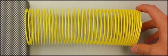
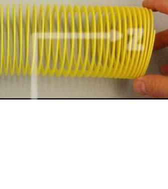
22 Compatibility Real World Examples

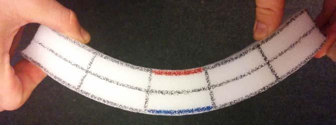
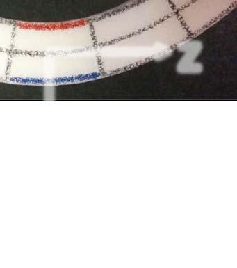
23 Compatibility Real World Examples
24 Superposition Difficult problem Multiple simple problems w(x) w(x) P 1 2 P
25 Anatomy of a Solid Mechanics Problem Compatibility Applied Loads Force-Displacement Relationship FD & Equilibrium Reaction & Internal Loads Stress Strain (Hooke s Law) Deformation Geometry Material Properties Statically Determinate Statically Indeterminate Performance Requirements
26 Stress Transformations Towards Failure Analysis Complex stress state including many components of shear and normal stress possible Stress state at a point depends on orientation y x σ x σ x θ τ x y τ xy σ y


27 Stress Transformations Towards Failure Analysis Orthogonal set of planes exist at every point where shear stress is zero Principle stress planes Max and min normal stress Known as Principle Stresses Plane of maximum shear stress Inclined 45 from principle stress plane Normal stresses can be non-zero Principle stresses Maximum shear stress
28 Stress Transformations Towards Failure Analysis Stress transformations can be described by equation of a circle (cw) τ Mohr Circle R ave τ yx θ y σ y A τ xy σ x x ave x 2 R 2 2 y x ave xy O τ xy σ y σ ave C R 2θ σ x A σ (ccw)

29 Stress Transformations Towards Failure Analysis Why do we care about stress transformations? Ductile failure rittle failure - Dictated by maximum shear stresses - Dictated by maximum normal stresses
30 Tresca Yield Criterion max yield 2 σ 2 σ 2 σ 1 O σ σ 2 +σ yield O σ 1 σ τ +σ yield τ σ 1 σ 1 -σ yield σ 1 σ 2 O σ -σ yield σ 2 O σ τ τ
31 Anatomy of a Solid Mechanics Problem Compatibility Applied Loads Force-Displacement Relationship FD & Equilibrium Reaction & Internal Loads Stress Strain (Hooke s Law) Deformation Geometry Material Properties Statically Determinate Statically Indeterminate Performance Requirements
32 Solving Solid Mechanics Problems General Procedure 1. Draw FD! Establish sign convention 2. Equilibrium Equations Determine if statically determinate or indeterminate 3. Compatibility Conditions 4. Force-Displacement Relations If force-displacement relation is unknown, use Hooke s Law to relate stress and strain 5. Solve Desired reaction forces Desired internal stresses Desired displacement
33 Solving Solid Mechanics Problems General Procedure Problem may have a design element Maximum load structure can carry Minimum span, height, or other geometrical parameter Design element centres around structural requirement Maximum allowable stress Maximum allowable deflection Principle stresses from Mohr Circle Failure criteria
34 Solving Solid Mechanics Problems Recommendations Describe your understanding of the problem in words first Is the problem statically determinate or indeterminate? What is the compatibility condition? Is there any trick to the problem? How does the design constraint affect the problem? Always look at your final numerical answer and reiterate the meaning of the sign Elongation or contraction? Tension or compression? Clockwise or counter clockwise rotation? Does the answer make sense, and if not, describe where you think you went wrong
35 Exam Hints There is always a Mohr Circle question! Difficult questions have a twist on a concept or condition you have analysed before: identify it and describe it
36 Past Exam Questions
37 exam question (1) Two identical thin walled beams (A & C) are connected at via a hinge. At A and at C the beams are clamped. eam A is loaded in bending by the load q A and beam C is loaded in bending by the load q C. Assume: (EI) A =(EI) C =EI L A =L C =L A C q A q C a) What is the deflection of point when q A =q C =q? b) What is the deflection of point when q A =2q C =2q? What is the twist? Hinge mid-span. Hinges can carry shear, but not moments, therefore the moment is zero midspan. Problem is both statically determinate and indeterminate
 FD: (Reactions at fixed boundary conditions not shown) A C Problem is symmetric!")
 Force-Displacement: z Standard")
38 a) What is the deflection of point when q A =q C =q? (I) FD: (Reactions at fixed boundary conditions not shown) A C Problem is symmetric! F F F 0 q q (since FD must be symmetric, and F must be equal and opposite on opposing faces) Since we only want displacement, we can recognize the standard case and skip directly to solving for displacement: (IV) Force-Displacement: z Standard Solution: v 4 ql 8EI 3 ql 6EI v 4 ql 8EI Deflection is downwards, which is logical for a distributed load acting downwards
 FD: (Reactions a fixed boundary conditions not shown) A C Problem is not symmetric!")
 Compatibility: eam deflection at must be the same for both beams v v A C (IV)")

39 b) What is the deflection of point when q A =2q C =2q? (I) FD: (Reactions a fixed boundary conditions not shown) A C Problem is not symmetric! F F F 0 2q q Problem is actually statically indeterminate! (III) Compatibility: eam deflection at must be the same for both beams v v A C (IV) Force-Displacement: 4 Standard Solutions: ql v z 8EI 3 ql 6EI z 3 PL v 3EI 2 PL 2EI v A qL FL ql FL 8EI 3EI 8EI 3EI 3 F ql ql 4 2qL FL 2qL 16 3qL 8EI 3EI 8EI 3EI 16EI Deflection is downwards, which is logical for a distributed load acting downwards
40 exam question(2) Consider the Airbus A380 aircraft: The engines of the A380 are suspended below the wing, having a distance of A 2.5m D 2.5 m between the centre of the wing box and the engine thrust line. This y C 2.5 m distance results in the engines imparting a torsional moment into the wingbox. Each of the A380 engines can generate approximately 350kN of thrust. The inboard engine is located 8m away from the wing root and the outboard engine is located 16m from the wing root. The wingbox is approximated as a constant cross section (figure above) with a fixed support condition at the wing-to-fuselage connection. a. Determine the maximum shear stress in the wingbox at the wing root (A) and the angle of twist relative to point A at each engine location in the wing ( and C) DUE TO THE TORQUE OF THE ENGINES ONLY. (G = 26 GPa) b. Part b is later (too much text for here!) c. Part c is later (too much text for here!) 8m 16m 30m 1m 3m t = 1cm What is the twist? Twist is in part b, will get to it later
41 a. Determine the maximum shear stress in the wingbox at the wing root (A) and the angle of twist relative to point A at each engine location in the wing ( and C) DUE TO THE TORQUE OF THE ENGINES ONLY. (G = 26 GPa) (I) FD: 875kNm T A 875kNm Engine torque = 350kN x 2.5m = 875kNm A C D (II) Equilibrium: T T kNm A Statically determinate! (IV) Solve: Shear Stress Thin walled torque box: T ta 2 A 3m1m3m m t 1cm0.01m T 1750kNm kNm A 29.2MPa m m
42 a. Determine the maximum shear stress in the wingbox at the wing root (A) and the angle of twist relative to point A at each engine location in the wing ( and C) DUE TO THE TORQUE OF THE ENGINES ONLY. (G = 26 GPa) (I) FD: T A 875kNm 875kNm A C D T-line TCD TC TA 0kNm 875kNm 1750kNm (IV) Solve: Angle of Twist Thin walled torque box: TL GA 2 4 m ds t Am ds t 3m ( m / m) rad degrees C rad degrees
43 b. The expression for the deflection of the wing due to distributed lift over the wing and engine weight is given below. ased on that expression (where x is distance from the wing root in meters, and force units in the expression are given in kn, and positive v is upwards in the direction of lift), plot the shear force diagram for the wing and the distributed load diagram (do not plot the bending moment diagram!) for 0 x8: EIv x x x x EIv x x x x for 8 16: for 16 x30: EIv 30 x x What is the twist? You can differentiate deflection to get loading for v EIv w x EIv V( x) EIv M( x) EIv for v wx EIv V ( x) EIv M ( x) A y 8m 16m 30m C 2.5m D 1m 3m t = 1cm
44 b. Plot the shear force diagram for the wing and the distributed load diagram 8m 16m 30m 3m A y 2.5m D 1m t = 1cm C for 0 x8: EIv x x x EIv ' x 1205x x 3 2 EIv '' 55x 2410x EIv ''' 110x 2410 V ( x) EIv '''' 110 w( x) x 1530 V -line kn x w -line kn/m
45 b. Plot the shear force diagram for the wing and the distributed load diagram 8m 16m 30m 3m A y 2.5m D 1m t = 1cm C EIv ' x 1235x x EIv '' 55x 2470x for 8 x16: EIv x x 87100x 1920x5120 EIv ''' 110x 2470 V ( x) EIv '''' 110 w( x) x V -line kn x w -line kn/m
46 b. Plot the shear force diagram for the wing and the distributed load diagram 8m 16m 30m 3m A y 2.5m D 1m t = 1cm x for 16 x30: EIv 30 x x EIv ' 1 (30 x) EIv '' (30 x) EIv ''' 1 (30 x) V ( x) EIv '''' (30 x) w( x) 7 V -line 710 x kn C w -line kn/m 2410
47 c. ased on your previous analysis, determine what the weight of each engine is (Point loads at and C in kn) and determine the total lift produced by the wing (resultant of distributed loads) 8m 16m 30m 3m A y 2.5m D 1m t = 1cm C x V -line kn 110 x w -line kn/m 2410 Engine weight : (-1590) = 60kN (positive is downwards, makes sense!) Lift : (-110)(8) + (-110)(8) + (0.5)(-110)(14) = kn (negative is upwards, makes sense!) (total thrust for one wing is (2)(350kN) = 700 kn, thus T/W < 1, which makes sense!)
48 exam question(3) steel steel max max adhesive 150MPa 80MPa max 5MPa A steel I-beam is to be reinforced by bonding plates of the same material to the top and bottom flanges as shown in the figure to the right. Given the above allowables: a) Determine the maximum bending moment that can be carried by the unreinforced beam. b) Determine the maximum shear force that can be carried by the unreinforced beam. c) Determine the maximum bending moment that can be carried by the reinforced beam. d) Determine the maximum shear force that can be carried by the reinforced beam. What is the twist? For reinforced beam, two conditions need to be checked for max shear force (part d): Transverse shear in steel I-beam and shear along adhesive bondline
49 A steel I-beam is to be reinforced by bonding plates of the same material to the top and bottom flanges as shown in the figure. a) Determine the maximum bending moment that can be carried by the unreinforced beam. 1 1 I 2 160mm20mm 20mm160 mm(210mm) 15mm400mm m MPa m My I, so M 247.2kNm I y 0.220m steel steel max max adhesive 150MPa 80MPa 5MPa max
50 A steel I-beam is to be reinforced by bonding plates of the same material to the top and bottom flanges as shown in the figure. b) Determine the maximum shear force that can be carried by the unreinforced beam. VQ Ib Ib sov Q steel steel max max adhesive 150MPa 80MPa 5MPa Q(200mm10 mm) (160mm20 mm) (100 mm) (200mm15 mm) m max Maximal shear is at the middle. I m V max 80MPa m m 4 3 m 447.5kN
51 A steel I-beam is to be reinforced by bonding plates of the same material to the top and bottom flanges as shown in the figure. c) Determine the maximum bending moment that can be carried by the reinforced beam. steel steel max max adhesive 150MPa 80MPa 5MPa max 1 Ireinf mm (15 mm) (150 mm)( 15 mm ) 22 0mm m mm 4 4 M reinf max 150 MPa m m kNm
52 A steel I-beam is to be reinforced by bonding plates of the same material to the top and bottom flanges as shown in the figure. d) Determine the maximum shear force that can be carried by the reinforced beam. Ib V Q Qreinf max I reinf m 4 4 steel steel max max adhesive 150MPa 80MPa 5MPa (0.220 ) max m V reinf max MPa m m m 481.9kN AND THE ONDLINE?
53 A steel I-beam is to be reinforced by bonding plates of the same material to the top and bottom flanges as shown in the figure. d) Determine the maximum shear force that can be carried by the reinforced beam. ONDLINE! Ib V Q I reinf m 4 4 steel steel max max adhesive 150MPa 80MPa 5MPa 15mm Qadh 220 mm 150mm mm 5.12 m 2 max V adh max MPa m 0.15m m kN Vreinf max 481.9kN
D : SOLID MECHANICS. Q. 1 Q. 9 carry one mark each. Q.1 Find the force (in kn) in the member BH of the truss shown.
 in the member BH of the truss shown.") D : SOLID MECHANICS Q. 1 Q. 9 carry one mark each. Q.1 Find the force (in kn) in the member BH of the truss shown. Q.2 Consider the forces of magnitude F acting on the sides of the regular hexagon having
D : SOLID MECHANICS Q. 1 Q. 9 carry one mark each. Q.1 Find the force (in kn) in the member BH of the truss shown. Q.2 Consider the forces of magnitude F acting on the sides of the regular hexagon having
PES Institute of Technology
 PES Institute of Technology Bangalore south campus, Bangalore-5460100 Department of Mechanical Engineering Faculty name : Madhu M Date: 29/06/2012 SEM : 3 rd A SEC Subject : MECHANICS OF MATERIALS Subject
Stress Analysis Lecture 4 ME 276 Spring Dr./ Ahmed Mohamed Nagib Elmekawy
 Stress Analysis Lecture 4 ME 76 Spring 017-018 Dr./ Ahmed Mohamed Nagib Elmekawy Shear and Moment Diagrams Beam Sign Convention The positive directions are as follows: The internal shear force causes a
QUESTION BANK SEMESTER: III SUBJECT NAME: MECHANICS OF SOLIDS
 QUESTION BANK SEMESTER: III SUBJECT NAME: MECHANICS OF SOLIDS UNIT 1- STRESS AND STRAIN PART A (2 Marks) 1. Define longitudinal strain and lateral strain. 2. State Hooke s law. 3. Define modular ratio,
D : SOLID MECHANICS. Q. 1 Q. 9 carry one mark each.
 GTE 2016 Q. 1 Q. 9 carry one mark each. D : SOLID MECHNICS Q.1 single degree of freedom vibrating system has mass of 5 kg, stiffness of 500 N/m and damping coefficient of 100 N-s/m. To make the system
Stress Analysis Lecture 3 ME 276 Spring Dr./ Ahmed Mohamed Nagib Elmekawy
 Stress Analysis Lecture 3 ME 276 Spring 2017-2018 Dr./ Ahmed Mohamed Nagib Elmekawy Axial Stress 2 Beam under the action of two tensile forces 3 Beam under the action of two tensile forces 4 Shear Stress
MAAE 2202 A. Come to the PASS workshop with your mock exam complete. During the workshop you can work with other students to review your work.
 It is most beneficial to you to write this mock final exam UNDER EXAM CONDITIONS. This means: Complete the exam in 3 hours. Work on your own. Keep your textbook closed. Attempt every question. After the
ME Final Exam. PROBLEM NO. 4 Part A (2 points max.) M (x) y. z (neutral axis) beam cross-sec+on. 20 kip ft. 0.2 ft. 10 ft. 0.1 ft.
 M (x) y. z (neutral axis) beam cross-sec+on. 20 kip ft. 0.2 ft. 10 ft. 0.1 ft.") ME 323 - Final Exam Name December 15, 2015 Instructor (circle) PROEM NO. 4 Part A (2 points max.) Krousgrill 11:30AM-12:20PM Ghosh 2:30-3:20PM Gonzalez 12:30-1:20PM Zhao 4:30-5:20PM M (x) y 20 kip ft 0.2
ME 323 - Final Exam Name December 15, 2015 Instructor (circle) PROEM NO. 4 Part A (2 points max.) Krousgrill 11:30AM-12:20PM Ghosh 2:30-3:20PM Gonzalez 12:30-1:20PM Zhao 4:30-5:20PM M (x) y 20 kip ft 0.2
Lecture M1 Slender (one dimensional) Structures Reading: Crandall, Dahl and Lardner 3.1, 7.2
 Structures Reading: Crandall, Dahl and Lardner 3.1, 7.2") Lecture M1 Slender (one dimensional) Structures Reading: Crandall, Dahl and Lardner 3.1, 7.2 This semester we are going to utilize the principles we learnt last semester (i.e the 3 great principles and
Lecture M1 Slender (one dimensional) Structures Reading: Crandall, Dahl and Lardner 3.1, 7.2 This semester we are going to utilize the principles we learnt last semester (i.e the 3 great principles and
Use Hooke s Law (as it applies in the uniaxial direction),
,") 0.6 STRSS-STRAIN RLATIONSHIP Use the principle of superposition Use Poisson s ratio, v lateral longitudinal Use Hooke s Law (as it applies in the uniaxial direction), x x v y z, y y vx z, z z vx y Copyright
0.6 STRSS-STRAIN RLATIONSHIP Use the principle of superposition Use Poisson s ratio, v lateral longitudinal Use Hooke s Law (as it applies in the uniaxial direction), x x v y z, y y vx z, z z vx y Copyright
[5] Stress and Strain
![[5] Stress and Strain](/thumbs/95/123344550.jpg "[5] Stress and Strain") [5] Stress and Strain Page 1 of 34 [5] Stress and Strain [5.1] Internal Stress of Solids [5.2] Design of Simple Connections (will not be covered in class) [5.3] Deformation and Strain [5.4] Hooke s Law
[5] Stress and Strain Page 1 of 34 [5] Stress and Strain [5.1] Internal Stress of Solids [5.2] Design of Simple Connections (will not be covered in class) [5.3] Deformation and Strain [5.4] Hooke s Law
QUESTION BANK DEPARTMENT: CIVIL SEMESTER: III SUBJECT CODE: CE2201 SUBJECT NAME: MECHANICS OF SOLIDS UNIT 1- STRESS AND STRAIN PART A
 DEPARTMENT: CIVIL SUBJECT CODE: CE2201 QUESTION BANK SEMESTER: III SUBJECT NAME: MECHANICS OF SOLIDS UNIT 1- STRESS AND STRAIN PART A (2 Marks) 1. Define longitudinal strain and lateral strain. 2. State
STRESS. Bar. ! Stress. ! Average Normal Stress in an Axially Loaded. ! Average Shear Stress. ! Allowable Stress. ! Design of Simple Connections
 STRESS! Stress Evisdom! verage Normal Stress in an xially Loaded ar! verage Shear Stress! llowable Stress! Design of Simple onnections 1 Equilibrium of a Deformable ody ody Force w F R x w(s). D s y Support
Failure from static loading
 Failure from static loading Topics Quiz /1/07 Failures from static loading Reading Chapter 5 Homework HW 3 due /1 HW 4 due /8 What is Failure? Failure any change in a machine part which makes it unable
[8] Bending and Shear Loading of Beams
![[8] Bending and Shear Loading of Beams](/thumbs/92/110949676.jpg "[8] Bending and Shear Loading of Beams") [8] Bending and Shear Loading of Beams Page 1 of 28 [8] Bending and Shear Loading of Beams [8.1] Bending of Beams (will not be covered in class) [8.2] Bending Strain and Stress [8.3] Shear in Straight
[8] Bending and Shear Loading of Beams Page 1 of 28 [8] Bending and Shear Loading of Beams [8.1] Bending of Beams (will not be covered in class) [8.2] Bending Strain and Stress [8.3] Shear in Straight
JUT!SI I I I TO BE RETURNED AT THE END OF EXAMINATION. THIS PAPER MUST NOT BE REMOVED FROM THE EXAM CENTRE. SURNAME: FIRST NAME: STUDENT NUMBER:
 JUT!SI I I I TO BE RETURNED AT THE END OF EXAMINATION. THIS PAPER MUST NOT BE REMOVED FROM THE EXAM CENTRE. SURNAME: FIRST NAME: STUDENT NUMBER: COURSE: Tutor's name: Tutorial class day & time: SPRING
Mechanics of Materials II. Chapter III. A review of the fundamental formulation of stress, strain, and deflection
 Mechanics of Materials II Chapter III A review of the fundamental formulation of stress, strain, and deflection Outline Introduction Assumtions and limitations Axial loading Torsion of circular shafts
STRENGTH OF MATERIALS-I. Unit-1. Simple stresses and strains
 STRENGTH OF MATERIALS-I Unit-1 Simple stresses and strains 1. What is the Principle of surveying 2. Define Magnetic, True & Arbitrary Meridians. 3. Mention different types of chains 4. Differentiate between
R13. II B. Tech I Semester Regular Examinations, Jan MECHANICS OF SOLIDS (Com. to ME, AME, AE, MTE) PART-A
 PART-A") SET - 1 II B. Tech I Semester Regular Examinations, Jan - 2015 MECHANICS OF SOLIDS (Com. to ME, AME, AE, MTE) Time: 3 hours Max. Marks: 70 Note: 1. Question Paper consists of two parts (Part-A and Part-B)
SET - 1 II B. Tech I Semester Regular Examinations, Jan - 2015 MECHANICS OF SOLIDS (Com. to ME, AME, AE, MTE) Time: 3 hours Max. Marks: 70 Note: 1. Question Paper consists of two parts (Part-A and Part-B)
σ = Eα(T T C PROBLEM #1.1 (4 + 4 points, no partial credit)
") PROBLEM #1.1 (4 + 4 points, no partial credit A thermal switch consists of a copper bar which under elevation of temperature closes a gap and closes an electrical circuit. The copper bar possesses a length
PROBLEM #1.1 (4 + 4 points, no partial credit A thermal switch consists of a copper bar which under elevation of temperature closes a gap and closes an electrical circuit. The copper bar possesses a length
7.4 The Elementary Beam Theory
 7.4 The Elementary Beam Theory In this section, problems involving long and slender beams are addressed. s with pressure vessels, the geometry of the beam, and the specific type of loading which will be
Purpose of this Guide: To thoroughly prepare students for the exact types of problems that will be on Exam 3.
 ES230 STRENGTH OF MTERILS Exam 3 Study Guide Exam 3: Wednesday, March 8 th in-class Updated 3/3/17 Purpose of this Guide: To thoroughly prepare students for the exact types of problems that will be on
BEAM A horizontal or inclined structural member that is designed to resist forces acting to its axis is called a beam
 BEM horizontal or inclined structural member that is designed to resist forces acting to its axis is called a beam INTERNL FORCES IN BEM Whether or not a beam will break, depend on the internal resistances
MECHANICS OF MATERIALS
 Third E CHAPTER 2 Stress MECHANICS OF MATERIALS Ferdinand P. Beer E. Russell Johnston, Jr. John T. DeWolf Lecture Notes: J. Walt Oler Texas Tech University and Strain Axial Loading Contents Stress & Strain:
Advanced Structural Analysis EGF Section Properties and Bending
 Advanced Structural Analysis EGF316 3. Section Properties and Bending 3.1 Loads in beams When we analyse beams, we need to consider various types of loads acting on them, for example, axial forces, shear
MECHANICS OF MATERIALS
 CHATR Stress MCHANICS OF MATRIALS and Strain Axial Loading Stress & Strain: Axial Loading Suitability of a structure or machine may depend on the deformations in the structure as well as the stresses induced
CE6306 STRENGTH OF MATERIALS TWO MARK QUESTIONS WITH ANSWERS ACADEMIC YEAR
 CE6306 STRENGTH OF MATERIALS TWO MARK QUESTIONS WITH ANSWERS ACADEMIC YEAR 2014-2015 UNIT - 1 STRESS, STRAIN AND DEFORMATION OF SOLIDS PART- A 1. Define tensile stress and tensile strain. The stress induced
1-1 Locate the centroid of the plane area shown. 1-2 Determine the location of centroid of the composite area shown.
 Chapter 1 Review of Mechanics of Materials 1-1 Locate the centroid of the plane area shown 650 mm 1000 mm 650 x 1- Determine the location of centroid of the composite area shown. 00 150 mm radius 00 mm
Introduction to Aerospace Engineering
 Introduction to Aerospace Engineering Lecture slides Challenge the future 1 Aircraft & spacecraft loads Translating loads to stresses Faculty of Aerospace Engineering 29-11-2011 Delft University of Technology
FINAL EXAMINATION. (CE130-2 Mechanics of Materials)
") UNIVERSITY OF CLIFORNI, ERKELEY FLL SEMESTER 001 FINL EXMINTION (CE130- Mechanics of Materials) Problem 1: (15 points) pinned -bar structure is shown in Figure 1. There is an external force, W = 5000N,
UNIVERSITY OF CLIFORNI, ERKELEY FLL SEMESTER 001 FINL EXMINTION (CE130- Mechanics of Materials) Problem 1: (15 points) pinned -bar structure is shown in Figure 1. There is an external force, W = 5000N,
National Exams May 2015
 National Exams May 2015 04-BS-6: Mechanics of Materials 3 hours duration Notes: If doubt exists as to the interpretation of any question, the candidate is urged to submit with the answer paper a clear
Chapter 4 Deflection and Stiffness
 Chapter 4 Deflection and Stiffness Asst. Prof. Dr. Supakit Rooppakhun Chapter Outline Deflection and Stiffness 4-1 Spring Rates 4-2 Tension, Compression, and Torsion 4-3 Deflection Due to Bending 4-4 Beam
Module 2. Analysis of Statically Indeterminate Structures by the Matrix Force Method
 Module 2 Analysis of Statically Indeterminate Structures by the Matrix Force Method Lesson 8 The Force Method of Analysis: Beams Instructional Objectives After reading this chapter the student will be
Structural Analysis I Chapter 4 - Torsion TORSION
 ORSION orsional stress results from the action of torsional or twisting moments acting about the longitudinal axis of a shaft. he effect of the application of a torsional moment, combined with appropriate
,. 'UTIS. . i. Univcnity of Technology, Sydney TO BE RETURNED AT THE END OF EXAMINATION. THIS PAPER MUST NOT BE REMOVED FROM THE EXAM CENTRE.
 ,. 'UTIS. i,i I Univcnity of Technology, Sydney TO BE RETURNED AT THE END OF EXAMINATION. THIS PAPER MUST NOT BE REMOVED FROM THE EXAM CENTRE. SURNAME: FIRST NAME: STUDENT NUMBER: COURSE: Tutor's name:
M5 Simple Beam Theory (continued)
") M5 Simple Beam Theory (continued) Reading: Crandall, Dahl and Lardner 7.-7.6 In the previous lecture we had reached the point of obtaining 5 equations, 5 unknowns by application of equations of elasticity
M5 Simple Beam Theory (continued) Reading: Crandall, Dahl and Lardner 7.-7.6 In the previous lecture we had reached the point of obtaining 5 equations, 5 unknowns by application of equations of elasticity
PROBLEM #1.1 (4 + 4 points, no partial credit)
") PROBLEM #1.1 ( + points, no partial credit A thermal switch consists of a copper bar which under elevation of temperature closes a gap and closes an electrical circuit. The copper bar possesses a length
PROBLEM #1.1 ( + points, no partial credit A thermal switch consists of a copper bar which under elevation of temperature closes a gap and closes an electrical circuit. The copper bar possesses a length
Name (Print) ME Mechanics of Materials Exam # 1 Date: October 5, 2016 Time: 8:00 10:00 PM
 ME Mechanics of Materials Exam # 1 Date: October 5, 2016 Time: 8:00 10:00 PM") Name (Print) (Last) (First) Instructions: ME 323 - Mechanics of Materials Exam # 1 Date: October 5, 2016 Time: 8:00 10:00 PM Circle your lecturer s name and your class meeting time. Gonzalez Krousgrill
Name (Print) (Last) (First) Instructions: ME 323 - Mechanics of Materials Exam # 1 Date: October 5, 2016 Time: 8:00 10:00 PM Circle your lecturer s name and your class meeting time. Gonzalez Krousgrill
SRI CHANDRASEKHARENDRA SARASWATHI VISWA MAHAVIDHYALAYA
 SRI CHANDRASEKHARENDRA SARASWATHI VISWA MAHAVIDHYALAYA (Declared as Deemed-to-be University under Section 3 of the UGC Act, 1956, Vide notification No.F.9.9/92-U-3 dated 26 th May 1993 of the Govt. of
Mechanical Properties of Materials
 Mechanical Properties of Materials Strains Material Model Stresses Learning objectives Understand the qualitative and quantitative description of mechanical properties of materials. Learn the logic of
KINGS COLLEGE OF ENGINEERING DEPARTMENT OF MECHANICAL ENGINEERING QUESTION BANK. Subject code/name: ME2254/STRENGTH OF MATERIALS Year/Sem:II / IV
 KINGS COLLEGE OF ENGINEERING DEPARTMENT OF MECHANICAL ENGINEERING QUESTION BANK Subject code/name: ME2254/STRENGTH OF MATERIALS Year/Sem:II / IV UNIT I STRESS, STRAIN DEFORMATION OF SOLIDS PART A (2 MARKS)
Chapter 5 Elastic Strain, Deflection, and Stability 1. Elastic Stress-Strain Relationship
 Chapter 5 Elastic Strain, Deflection, and Stability Elastic Stress-Strain Relationship A stress in the x-direction causes a strain in the x-direction by σ x also causes a strain in the y-direction & z-direction
(Refer Slide Time: 2:43-03:02)
") Strength of Materials Prof. S. K. Bhattacharyya Department of Civil Engineering Indian Institute of Technology, Kharagpur Lecture - 34 Combined Stresses I Welcome to the first lesson of the eighth module
Strength of Materials Prof. S. K. Bhattacharyya Department of Civil Engineering Indian Institute of Technology, Kharagpur Lecture - 34 Combined Stresses I Welcome to the first lesson of the eighth module
MECH 401 Mechanical Design Applications
 MECH 401 Mechanical Design Applications Dr. M. O Malley Master Notes Spring 008 Dr. D. M. McStravick Rice University Updates HW 1 due Thursday (1-17-08) Last time Introduction Units Reliability engineering
Virtual Work & Energy Methods. External Energy-Work Transformation
 External Energy-Work Transformation Virtual Work Many structural problems are statically determinate (support reactions & internal forces can be found by simple statics) Other methods are required when
March 24, Chapter 4. Deflection and Stiffness. Dr. Mohammad Suliman Abuhaiba, PE
 Chapter 4 Deflection and Stiffness 1 2 Chapter Outline Spring Rates Tension, Compression, and Torsion Deflection Due to Bending Beam Deflection Methods Beam Deflections by Superposition Strain Energy Castigliano
Consider an elastic spring as shown in the Fig.2.4. When the spring is slowly
 .3 Strain Energy Consider an elastic spring as shown in the Fig..4. When the spring is slowly pulled, it deflects by a small amount u 1. When the load is removed from the spring, it goes back to the original
Stress Transformation Equations: u = +135 (Fig. a) s x = 80 MPa s y = 0 t xy = 45 MPa. we obtain, cos u + t xy sin 2u. s x = s x + s y.
 s x = 80 MPa s y = 0 t xy = 45 MPa. we obtain, cos u + t xy sin 2u. s x = s x + s y.") 014 Pearson Education, Inc., Upper Saddle River, NJ. All rights reserved. This material is protected under all copyright laws as they currently 9 7. Determine the normal stress and shear stress acting
014 Pearson Education, Inc., Upper Saddle River, NJ. All rights reserved. This material is protected under all copyright laws as they currently 9 7. Determine the normal stress and shear stress acting
STRESS STRAIN AND DEFORMATION OF SOLIDS, STATES OF STRESS
 1 UNIT I STRESS STRAIN AND DEFORMATION OF SOLIDS, STATES OF STRESS 1. Define: Stress When an external force acts on a body, it undergoes deformation. At the same time the body resists deformation. The
Chapter 8 Structural Design and Analysis. Strength and stiffness 5 types of load: Tension Compression Shear Bending Torsion
 Chapter 8 Structural Design and Analysis 1 Strength and stiffness 5 types of load: Tension Compression Shear Bending Torsion Normal Stress Stress is a state when a material is loaded. For normal forces
MECHANICS OF MATERIALS
 2009 The McGraw-Hill Companies, Inc. All rights reserved. Fifth SI Edition CHAPTER 3 MECHANICS OF MATERIALS Ferdinand P. Beer E. Russell Johnston, Jr. John T. DeWolf David F. Mazurek Torsion Lecture Notes:
Comb resonator design (2)
") Lecture 6: Comb resonator design () -Intro Intro. to Mechanics of Materials School of Electrical l Engineering i and Computer Science, Seoul National University Nano/Micro Systems & Controls Laboratory
Lecture 6: Comb resonator design () -Intro Intro. to Mechanics of Materials School of Electrical l Engineering i and Computer Science, Seoul National University Nano/Micro Systems & Controls Laboratory
(48) CHAPTER 3: TORSION
 CHAPTER 3: TORSION") (48) CHAPTER 3: TORSION Introduction: In this chapter structural members and machine parts that are in torsion will be considered. More specifically, you will analyze the stresses and strains in members
(48) CHAPTER 3: TORSION Introduction: In this chapter structural members and machine parts that are in torsion will be considered. More specifically, you will analyze the stresses and strains in members
Mechanics of Materials Primer
 Mechanics of Materials rimer Notation: A = area (net = with holes, bearing = in contact, etc...) b = total width of material at a horizontal section d = diameter of a hole D = symbol for diameter E = modulus
Strength of Materials Prof. S.K.Bhattacharya Dept. of Civil Engineering, I.I.T., Kharagpur Lecture No.26 Stresses in Beams-I
 Strength of Materials Prof. S.K.Bhattacharya Dept. of Civil Engineering, I.I.T., Kharagpur Lecture No.26 Stresses in Beams-I Welcome to the first lesson of the 6th module which is on Stresses in Beams
Problem d d d B C E D. 0.8d. Additional lecturebook examples 29 ME 323
 Problem 9.1 Two beam segments, AC and CD, are connected together at C by a frictionless pin. Segment CD is cantilevered from a rigid support at D, and segment AC has a roller support at A. a) Determine
UNIT- I Thin plate theory, Structural Instability:
 UNIT- I Thin plate theory, Structural Instability: Analysis of thin rectangular plates subject to bending, twisting, distributed transverse load, combined bending and in-plane loading Thin plates having
Shafts: Torsion of Circular Shafts Reading: Crandall, Dahl and Lardner 6.2, 6.3
 M9 Shafts: Torsion of Circular Shafts Reading: Crandall, Dahl and Lardner 6., 6.3 A shaft is a structural member which is long and slender and subject to a torque (moment) acting about its long axis. We
 UNIT III DEFLECTION OF BEAMS 1. What are the methods for finding out the slope and deflection at a section? The important methods used for finding out the slope and deflection at a section in a loaded
Torsion of Solid Sections. Introduction
 Introduction Torque is a common load in aircraft structures In torsion of circular sections, shear strain is a linear function of radial distance Plane sections are assumed to rotate as rigid bodies These
2. (a) Explain different types of wing structures. (b) Explain the advantages and disadvantages of different materials used for aircraft
 Explain different types of wing structures. (b) Explain the advantages and disadvantages of different materials used for aircraft") Code No: 07A62102 R07 Set No. 2 III B.Tech II Semester Regular/Supplementary Examinations,May 2010 Aerospace Vehicle Structures -II Aeronautical Engineering Time: 3 hours Max Marks: 80 Answer any FIVE
Code No: 07A62102 R07 Set No. 2 III B.Tech II Semester Regular/Supplementary Examinations,May 2010 Aerospace Vehicle Structures -II Aeronautical Engineering Time: 3 hours Max Marks: 80 Answer any FIVE
External Work. When a force F undergoes a displacement dx in the same direction i as the force, the work done is
 Structure Analysis I Chapter 9 Deflection Energy Method External Work Energy Method When a force F undergoes a displacement dx in the same direction i as the force, the work done is du e = F dx If the
UNIT 1 STRESS STRAIN AND DEFORMATION OF SOLIDS, STATES OF STRESS 1. Define stress. When an external force acts on a body, it undergoes deformation.
 UNIT 1 STRESS STRAIN AND DEFORMATION OF SOLIDS, STATES OF STRESS 1. Define stress. When an external force acts on a body, it undergoes deformation. At the same time the body resists deformation. The magnitude
18.Define the term modulus of resilience. May/June Define Principal Stress. 20. Define Hydrostatic Pressure.
 CE6306 STREGNTH OF MATERIALS Question Bank Unit-I STRESS, STRAIN, DEFORMATION OF SOLIDS PART-A 1. Define Poison s Ratio May/June 2009 2. What is thermal stress? May/June 2009 3. Estimate the load carried
UNIT-I STRESS, STRAIN. 1. A Member A B C D is subjected to loading as shown in fig determine the total elongation. Take E= 2 x10 5 N/mm 2
 UNIT-I STRESS, STRAIN 1. A Member A B C D is subjected to loading as shown in fig determine the total elongation. Take E= 2 x10 5 N/mm 2 Young s modulus E= 2 x10 5 N/mm 2 Area1=900mm 2 Area2=400mm 2 Area3=625mm
EMA 3702 Mechanics & Materials Science (Mechanics of Materials) Chapter 2 Stress & Strain - Axial Loading
 Chapter 2 Stress & Strain - Axial Loading") MA 3702 Mechanics & Materials Science (Mechanics of Materials) Chapter 2 Stress & Strain - Axial Loading MA 3702 Mechanics & Materials Science Zhe Cheng (2018) 2 Stress & Strain - Axial Loading Statics
MA 3702 Mechanics & Materials Science (Mechanics of Materials) Chapter 2 Stress & Strain - Axial Loading MA 3702 Mechanics & Materials Science Zhe Cheng (2018) 2 Stress & Strain - Axial Loading Statics
CIV E 205 Mechanics of Solids II. Course Notes
 Department of Civil Engineering CIV E 205 Mechanics of Solids II Instructor: Tarek Hegazi Email: tarek@uwaterloo.ca Course Notes Mechanics of Materials Objectives: - Solve Problems in a structured systematic
Beams. Beams are structural members that offer resistance to bending due to applied load
 Beams Beams are structural members that offer resistance to bending due to applied load 1 Beams Long prismatic members Non-prismatic sections also possible Each cross-section dimension Length of member
NAME: Given Formulae: Law of Cosines: Law of Sines:
 NME: Given Formulae: Law of Cosines: EXM 3 PST PROBLEMS (LESSONS 21 TO 28) 100 points Thursday, November 16, 2017, 7pm to 9:30, Room 200 You are allowed to use a calculator and drawing equipment, only.
Free Body Diagram: Solution: The maximum load which can be safely supported by EACH of the support members is: ANS: A =0.217 in 2
 Problem 10.9 The angle β of the system in Problem 10.8 is 60. The bars are made of a material that will safely support a tensile normal stress of 8 ksi. Based on this criterion, if you want to design the
If the number of unknown reaction components are equal to the number of equations, the structure is known as statically determinate.
 1 of 6 EQUILIBRIUM OF A RIGID BODY AND ANALYSIS OF ETRUCTURAS II 9.1 reactions in supports and joints of a two-dimensional structure and statically indeterminate reactions: Statically indeterminate structures
CHAPTER THREE SYMMETRIC BENDING OF CIRCLE PLATES
 CHAPTER THREE SYMMETRIC BENDING OF CIRCLE PLATES * Governing equations in beam and plate bending ** Solution by superposition 1.1 From Beam Bending to Plate Bending 1.2 Governing Equations For Symmetric
Downloaded from Downloaded from / 1
 PURWANCHAL UNIVERSITY III SEMESTER FINAL EXAMINATION-2002 LEVEL : B. E. (Civil) SUBJECT: BEG256CI, Strength of Material Full Marks: 80 TIME: 03:00 hrs Pass marks: 32 Candidates are required to give their
Deflection of Flexural Members - Macaulay s Method 3rd Year Structural Engineering
 Deflection of Flexural Members - Macaulay s Method 3rd Year Structural Engineering 009/10 Dr. Colin Caprani 1 Contents 1. Introduction... 4 1.1 General... 4 1. Background... 5 1.3 Discontinuity Functions...
two structural analysis (statics & mechanics) APPLIED ACHITECTURAL STRUCTURES: DR. ANNE NICHOLS SPRING 2017 lecture STRUCTURAL ANALYSIS AND SYSTEMS
 APPLIED ACHITECTURAL STRUCTURES: DR. ANNE NICHOLS SPRING 2017 lecture STRUCTURAL ANALYSIS AND SYSTEMS") APPLIED ACHITECTURAL STRUCTURES: STRUCTURAL ANALYSIS AND SYSTEMS DR. ANNE NICHOLS SPRING 2017 lecture two structural analysis (statics & mechanics) Analysis 1 Structural Requirements strength serviceability
APPLIED ACHITECTURAL STRUCTURES: STRUCTURAL ANALYSIS AND SYSTEMS DR. ANNE NICHOLS SPRING 2017 lecture two structural analysis (statics & mechanics) Analysis 1 Structural Requirements strength serviceability
3. BEAMS: STRAIN, STRESS, DEFLECTIONS
 3. BEAMS: STRAIN, STRESS, DEFLECTIONS The beam, or flexural member, is frequently encountered in structures and machines, and its elementary stress analysis constitutes one of the more interesting facets
Module 2 Stresses in machine elements. Version 2 ME, IIT Kharagpur
 Module Stresses in machine elements Lesson Compound stresses in machine parts Instructional Objectives t the end of this lesson, the student should be able to understand Elements of force system at a beam
UNIVERSITY OF SASKATCHEWAN ME MECHANICS OF MATERIALS I FINAL EXAM DECEMBER 13, 2008 Professor A. Dolovich
 UNIVERSITY OF SASKATCHEWAN ME 313.3 MECHANICS OF MATERIALS I FINAL EXAM DECEMBER 13, 2008 Professor A. Dolovich A CLOSED BOOK EXAMINATION TIME: 3 HOURS For Marker s Use Only LAST NAME (printed): FIRST
SSC-JE MAINS ONLINE TEST SERIES / CIVIL ENGINEERING SOM + TOS
 SSC-JE MAINS ONLINE TEST SERIES / CIVIL ENGINEERING SOM + TOS Time Allowed:2 Hours Maximum Marks: 300 Attention: 1. Paper consists of Part A (Civil & Structural) Part B (Electrical) and Part C (Mechanical)
2. Rigid bar ABC supports a weight of W = 50 kn. Bar ABC is pinned at A and supported at B by rod (1). What is the axial force in rod (1)?
. What is the axial force in rod (1)?") IDE 110 S08 Test 1 Name: 1. Determine the internal axial forces in segments (1), (2) and (3). (a) N 1 = kn (b) N 2 = kn (c) N 3 = kn 2. Rigid bar ABC supports a weight of W = 50 kn. Bar ABC is pinned at
IDE 110 S08 Test 1 Name: 1. Determine the internal axial forces in segments (1), (2) and (3). (a) N 1 = kn (b) N 2 = kn (c) N 3 = kn 2. Rigid bar ABC supports a weight of W = 50 kn. Bar ABC is pinned at
Combined Stresses and Mohr s Circle. General Case of Combined Stresses. General Case of Combined Stresses con t. Two-dimensional stress condition
 Combined Stresses and Mohr s Circle Material in this lecture was taken from chapter 4 of General Case of Combined Stresses Two-dimensional stress condition General Case of Combined Stresses con t The normal
Members Subjected to Torsional Loads
 Members Subjected to Torsional Loads Torsion of circular shafts Definition of Torsion: Consider a shaft rigidly clamped at one end and twisted at the other end by a torque T = F.d applied in a plane perpendicular
DESIGN OF BEAMS AND SHAFTS
 DESIGN OF EAMS AND SHAFTS! asis for eam Design! Stress Variations Throughout a Prismatic eam! Design of pristmatic beams! Steel beams! Wooden beams! Design of Shaft! ombined bending! Torsion 1 asis for
MECHANICS OF MATERIALS. Prepared by Engr. John Paul Timola
 MECHANICS OF MATERIALS Prepared by Engr. John Paul Timola Mechanics of materials branch of mechanics that studies the internal effects of stress and strain in a solid body. stress is associated with the
Static Failure (pg 206)
") Static Failure (pg 06) All material followed Hookeʹs law which states that strain is proportional to stress applied, until it exceed the proportional limits. It will reach and exceed the elastic limit
Static Failure (pg 06) All material followed Hookeʹs law which states that strain is proportional to stress applied, until it exceed the proportional limits. It will reach and exceed the elastic limit
ME 323 Examination #2 April 11, 2018
 ME 2 Eamination #2 April, 2 PROBLEM NO. 25 points ma. A thin-walled pressure vessel is fabricated b welding together two, open-ended stainless-steel vessels along a 6 weld line. The welded vessel has an
Q. 1 Q. 5 carry one mark each.
 General ptitude G Set-8 Q. 1 Q. 5 carry one mark each. Q.1 The chairman requested the aggrieved shareholders to him. () bare with () bore with (C) bear with (D) bare Q.2 Identify the correct spelling out
CHAPTER OBJECTIVES Use various methods to determine the deflection and slope at specific pts on beams and shafts: 2. Discontinuity functions
 1. Deflections of Beams and Shafts CHAPTER OBJECTIVES Use various methods to determine the deflection and slope at specific pts on beams and shafts: 1. Integration method. Discontinuity functions 3. Method
1 Static Plastic Behaviour of Beams
 1 Static Plastic Behaviour of Beams 1.1 Introduction Many ductile materials which are used in engineering practice have a considerable reserve capacity beyond the initial yield condition. The uniaxial
Deflection of Flexural Members - Macaulay s Method 3rd Year Structural Engineering
 Deflection of Flexural Members - Macaulay s Method 3rd Year Structural Engineering 008/9 Dr. Colin Caprani 1 Contents 1. Introduction... 3 1.1 General... 3 1. Background... 4 1.3 Discontinuity Functions...
Physics 8 Monday, November 20, 2017
 Physics 8 Monday, November 20, 2017 Pick up HW11 handout, due Dec 1 (Friday next week). This week, you re skimming/reading O/K ch8, which goes into more detail on beams. Since many people will be traveling
Unit 13 Review of Simple Beam Theory
 MIT - 16.0 Fall, 00 Unit 13 Review of Simple Beam Theory Readings: Review Unified Engineering notes on Beam Theory BMP 3.8, 3.9, 3.10 T & G 10-15 Paul A. Lagace, Ph.D. Professor of Aeronautics & Astronautics
GATE SOLUTIONS E N G I N E E R I N G
 GATE SOLUTIONS C I V I L E N G I N E E R I N G From (1987-018) Office : F-16, (Lower Basement), Katwaria Sarai, New Delhi-110016 Phone : 011-65064 Mobile : 81309090, 9711853908 E-mail: info@iesmasterpublications.com,
Aircraft Stress Analysis and Structural Design Summary
 Aircraft Stress Analysis and Structural Design Summary 1. Trusses 1.1 Determinacy in Truss Structures 1.1.1 Introduction to determinacy A truss structure is a structure consisting of members, connected
Sub. Code:
 Important Instructions to examiners: ) The answers should be examined by key words and not as word-to-word as given in the model answer scheme. ) The model answer and the answer written by candidate may
PERIYAR CENTENARY POLYTECHNIC COLLEGE PERIYAR NAGAR - VALLAM THANJAVUR. DEPARTMENT OF MECHANICAL ENGINEERING QUESTION BANK
 PERIYAR CENTENARY POLYTECHNIC COLLEGE PERIYAR NAGAR - VALLAM - 613 403 - THANJAVUR. DEPARTMENT OF MECHANICAL ENGINEERING QUESTION BANK Sub : Strength of Materials Year / Sem: II / III Sub Code : MEB 310
CHAPTER 4: BENDING OF BEAMS
 (74) CHAPTER 4: BENDING OF BEAMS This chapter will be devoted to the analysis of prismatic members subjected to equal and opposite couples M and M' acting in the same longitudinal plane. Such members are
Solution ME 323 EXAM #2 FALL SEMESTER :00 PM 9:30 PM Nov. 2, 2010
 Solution ME 33 EXAM # FALL SEMESTER 1 8: PM 9:3 PM Nov., 1 Instructions 1. Begin each problem in the space provided on the eamination sheets. If additional space is required, use the paper provided. Work
STATICALLY INDETERMINATE STRUCTURES
 STATICALLY INDETERMINATE STRUCTURES INTRODUCTION Generally the trusses are supported on (i) a hinged support and (ii) a roller support. The reaction components of a hinged support are two (in horizontal
3 Hours/100 Marks Seat No.
 *17304* 17304 14115 3 Hours/100 Marks Seat No. Instructions : (1) All questions are compulsory. (2) Illustrate your answers with neat sketches wherever necessary. (3) Figures to the right indicate full