FOUR-POINT CONTACT SLEWING RINGS - without gear [ O ]
|
|
|
- Robyn Smith
- 5 years ago
- Views:
Transcription
1 FOUR-POINT CONTACT SLEWING RINGS - without gear [ O ] Number of the Loading Boundary Dimensions Static Ax.Basic Load Rating Designation Weight Abutment Dimensions Curve d D T C oa G J 1 J 2 N 1 N 2 n 1 n 2 [kg] B M B B B /2-13 UNC B /8-11 UNC B M16 M B M10 M B B /2-13 UNC 1/2-13 UNC B M B /8-11 UNC B /8-11 UNC B B B B M B B B B B M B M18x1.5 M18x B B S M12 M B B M16 M B Other Specifications Note No d 1 D 1 H B ; ; Notes 1 Fixing holes on inner ring are divided on the circumference with spacing a 360 /16 2 Fixing holes on outer ring are recessed on 20.3 into the depth of Fixing holes on inner ring are divided on the circumference with spacing a 360 /20 4 Non-through tapped fixing holes on outer ring 5 Fixing holes on outer ring are recessed on 25.4 into the depth of Non-through tapped fixing holes on inner ring 7 Fixing holes on both rings are recessed on 33 into the depth of 13 8 Fixing holes on outer ring are divided on the circumference with spacing a 360 /16 9 Fixing holes on inner ring are recessed on 32 into the depth of 13
2 Mouting Procedure Before assembling it is necessary to clean all surfaces thoroughly from burrs, paint residues, etc. Seating surfaces should be dry, without lubricant. Furthermore it is necessary to inspect flatness of the seating surfaces. Feeler gauges are used to check slewing ring adaptation. Backlash The unhardened area of the non rotating ring should be mounted so that it is positioned in the least loaded zone - i.e. in the plane perpendicular to the main load plane. The unhardened area is marked on the respective ring non-functional surface with symbol "X" by stamping or with a red line. When assembling a geared slewing ring it is important to adjust the backlash in the gear correctly. It is adjusted with a feeler gauge or with another suitable method in the zone of maximum radial gear runout. The extent of the backlash should be in the range of ( ).m, where "m" means the gear module. The backlash should be inspected again after the slewing ring is finally fixed on the machine. The zone of the maximum radial gear runout is marked with a blue line in the gap between teeth. Sequence of bolts tightening Slewing rings are fixed on the machine with pre-stressed bolts. Before assembly the mounting bolts should be coated slightly with oil. The necessary tightening torgue for corresponding bolt size and material is indicated in Table 1. Table 1 Bolt Thread Size Bore Diameter Tightening torgue at µ = 0.14 [Nm] DIN/ISO 273 Rigidity Class of Bolt 8.8 Rigidity Class of Bolt 10.9 M M M M M M M M Grade 5 Grade 8 UNC 5/ UNC 3/ UNC 7/ UNC UNC 1 1/ UNC 1 1/ Grade 5 Grade 8 UNF 5/ UNF 3/ UNF 7/ UNF UNF 1 1/ UNF 1 1/
3 Slewing Ring Inspection in Operation During service it is necessary to regularly recheck the fixing bolts torque at the in recommended intervals. Individual inspection intervals vary according to machine operation conditions. When inspecting, the following method can be used (approximately valid for crane operation): Inspection No. Number of Operating Hours Inspecting Action 1. About 200 Hours - inspection of all bolts torque - if more than 10% of bolts are loose, another inspection is necessary after about 200 operating hours 2. About 600 Hours - inspection of all bolts torque 3. and further After about Hours - if one or more bolts are loose to less than 80% of the prescribed torque, these and both adjoining bolts must be replaced by new ones - if 20% of all bolts have less than 80% of prescribed torque, all bolts must be replaced by new ones Each Hours - replace all bolts by new ones Note: Specified inspection intervals must be shortened by 1/2 up to 1/3 for machines loaded more heavily by vibrations or dynamically. In addition to the fixing bolts check, raceway wear checking is also carried out in operation ( mainly at significant important rotary connections) using the measurement method "tilting clearance". The tilting clearance is the difference of the mutual ring displacement in axial direction measured under load by minimum and maximum tilting moment. In the operation register of the equipment the initial tilting clearance is recorded (in the jib position 1 to 8) and its enlargement is then followed in certain time intervals. The principle of the tilting clearance measurement and an example of the measuring record are shown in Figure 3. More detailed technical information concerning slewing ring checking can be provided by the experts of PSL, Technical Consultancy Department. Figure 3 Upper Construction Jib Position Lower Construction Measuring Spot Slewing Ring Tables The following Tables (pages 14-27) show the standard PSL slewing rings whose cross-section corresponds to the figure above the Table. Any deviations are specified in the notes. Further Tables (pages 28-30) show special slewing rings whose cross-section does not correspond to the figures over the Tables, or they differ from the standard design (e.g. they have irregular spacing of the fastening holes, special gear, higher tolerance class, are non-sealed from one or both sides, or have non-standard shape of the rings, etc.). More detailed information concerning these slewing rings can be provided by the experts of the PSL Technical Consultancy Department, address - see page 2. The tables of the special slewing rings show some types designated by the designation PSL They are slewing rings of the old three-ring design (one ring is split).
4 FOUR-POINT CONTACT BALL SLEWING RINGS -with external gear [ E ] Number of the Loading Boundary Dimensions Static Ax.Basic Load Rating Designation Weight Abutment Dimensions Curve d D T C oa G J 1 J 2 N 1 N 2 n 1 n 2 [kg] E-1B /8-11 UNC 5/8-11 UNC E-1B /8-11 UNC 5/8-11 UNC E-1B /8-11 UNC 5/8-11 UNC E-1B /8-11 UNC 5/8-11 UNC E-1B E-1B E-1B /8-11 UNC 5/8-11 UNC E-1B /8-11 UNC 5/8-11 UNC E-1B /8-11 UNC E-1B /2-13 UNC E-1B /8-11 UNC 5/8-11 UNC E-1B /8-11 UNC 5/8-11 UNC E-1B /4-10 UNC E-1B /8-11 UNC 5/8-11 UNC E-1B M16 M E-1B E-1B /4-10 UNC E-1B E-1B E-1B M E-1B E-1B M E-1B M E-1B /8-14 UNC 7/8-14 UNC E-1B UNC E-1B UNC 1-8 UNC E-1B M20 M E-1B E-1B /8-12 UNC E-1B /4-16 UNF 3/4-16 UNF E-1B E-1B /8-11 UNC E-1B M Other Specifications d 1 D 1 H B B 1 m(dp) (5) ; ; (5/7) ; ; (5/7) ; (5/7) (5/7) (5/7) (5/7) (4) ; (5/7) ; ; (4) ; 8; 12; (4) ; 14; (4) ; 14; (4/5) ; (4/5) ; 13; (4/5) ; 9; (2) ; (2.5) (2.5) z x Permisible Note No circumferencial force F TDov F TmaxDov Notes 1 Right-hand helical gear α = 20 ; β = 6 2 Right-hand helical gear α = ; β = 6 3 Fixing holes on inner ring are divided on the circumference with spacing a 360 /16 4 Gear Fellows Stub α = 20 5 Fixing holes on inner ring are divided on the circumference with spacing a 360 /28 6 Centering diameter is on the opposite bearing face 7 Fixing holes on inner ring are divided on the circumference with spacing a 360 /24 8 Gear Involute Stub α = 20 9 Non-through tapped fixing holes on both rings 10 Gear Fellow Stub Tooth System Special-Full Fillet Radius α = Fixing holes on inner ring are divided on the circumference with spacing a 360 /36 12 Fixing holes on inner ring are recessed on 50 into the depth of Non-through tapped fixing holes on outer ring 14 Fixing holes on both rings ring are recessed on 30 into the depth of Gear Agma Stub α = Fixing holes on inner ring are divided on the circumference with spacing a 360 /30 (two places a 180 are not occupied) 17 Fixing holes on inner ring are recessed on 21 into the depth of Fixing holes on inner ring are divided on the circumference with spacing a 360 /30 19 Fixing holes on inner ring are divided on the circumference with spacing a 360 /40 20 Fixing holes on outer ring are recessed on 41.3 into the depth of Gear Involute Stub-Full Fillet radius α = Fixing holes on inner ring are divided on the circumference with spacing a 360 /52 23 Fixing holes on both rings ring are recessed on 34 into the depth of 16
5 FOUR-POINT CONTACT BALL SLEWING RINGS -with external gear [ E ] (continued) Number of the Loading Boundary Dimensions Static Ax.Basic Load Rating Designation Weight Abutment Dimensions Curve d D T C oa G J 1 J 2 N 1 N 2 n 1 n 2 [kg] E-1B E-1B M E-1B /4-7 UNC 11/4-7 UNC E-1B UNC 1-8 UNC E-1B E-1B E-1B E-1B Other Specifications d 1 D 1 H B B 1 m(dp) (2) (2) ; (2) ; (1.5) (2.5) z x Permisible Note No circumferencial force F TDov F TmaxDov Notes 1 Right-hand helical gear α = 20 ; β = 6 2 Right-hand helical gear α = ; β = 6 3 Fixing holes on inner ring are divided on the circumference with spacing a 360 /16 4 Gear Fellows Stub α = 20 5 Fixing holes on inner ring are divided on the circumference with spacing a 360 /28 6 Centering diameter is on the opposite bearing face 7 Fixing holes on inner ring are divided on the circumference with spacing a 360 /24 8 Gear Involute Stub α = 20 9 Non-through tapped fixing holes on both rings 10 Gear Fellow Stub Tooth System Special-Full Fillet Radius α = Fixing holes on inner ring are divided on the circumference with spacing a 360 /36 12 Fixing holes on inner ring are recessed on 50 into the depth of Non-through tapped fixing holes on outer ring 14 Fixing holes on both rings ring are recessed on 30 into the depth of Gear Agma Stub α = Fixing holes on inner ring are divided on the circumference with spacing a 360 /30 (two places a 180 are not occupied) 17 Fixing holes on inner ring are recessed on 21 into the depth of Fixing holes on inner ring are divided on the circumference with spacing a 360 /30 19 Fixing holes on inner ring are divided on the circumference with spacing a 360 /40 20 Fixing holes on outer ring are recessed on 41.3 into the depth of Gear Involute Stub-Full Fillet radius α = Fixing holes on inner ring are divided on the circumference with spacing a 360 /52 23 Fixing holes on both rings ring are recessed on 34 into the depth of 16
6 FOUR-POINT CONTACT BALL SLEWING RINGS -with internal gear [ I ] Number of the Loading Boundary Dimensions Static Ax.Basic Load Rating Designation Weight Abutment Dimensions Curve d D T C oa G J 1 J 2 N 1 N 2 n 1 n 2 [kg] I-1B /8-11 UNC 5/8-11 UNC I-1B /8-11 UNC 5/8-11 UNC I-1B M12x I-1B /8-11 UNC I-1B /4-10 UNC I-1B /4-10 UNC I-1B M I-1B M I-1B /4-10 UNC I-1B /4-10 UNC 3/4-10 UNC I-1B /4-16 UNF 3/4-16 UNF I-1B M16 M I-1B /2-13 UNC I-1B M I-1B /4-10 UNC 3/4-10 UNC I-1B M16 M I-1B /4-10 UNC 3/4-10 UNC I-1B /4-10 UNC 3/4-10 UNC I-1B M I-1B M20x I-1B /8-11 UNC I-1B /4-10 UNC UNC I-1B /4-10 UNC 3/4-10 UNC I-1B UNC I-1B /8-9 UNC I-1B UNC I-1B M I-1B M20x I-1B M I-1B M24x I-1B Other Specifications d 1 D 1 H B B 1 m(dp) (5/7) (5/7) ; (4) ; (4) ; (4) ; (3.5) (4) ; (4) ; (4) ; (4) ; (3.5) ; (3.5) ; (2.5) ; (2.5) ; 7; (2.5) ; (2.5) ; (2.5) ; (2.5) ; ; z x Permisible Note No. circumferencial force F TDov F TmaxDov Notes 1 Gear Fellow Stub Tooth System α = 20 2 Non-through tapped fixing holes on both rings 3 Non-through tapped fixing holes on inner ring 4 Gear Involute Stub α = 20 5 Fixing holes on outer ring are divided on the circumference with spacing a 360 /52 6 Centering diameter is on both sides of the ring (on the front face into the depth of 1. on the opposite face into the depth 9.4) 7 Gear Involute Stub-Full Fillet Radius α = 20 8 Opposite face of the inner ring is fitted on into the depth Gear Involute Modification Stub-Full Fillet Radius α = Fixing holes on outer ring are divided on the circumference with spacing a 360 /36
7 SELECTION OF SLEWING RING TYPE AND SIZE Selection of a suitable slewing ring for common applications can be carried out from the point of view of the static load rating by means of the diagrams (curves) for the limiting static load of the raceways and fixing bolts (pages of this publication) based on the calculated equivalent axial and moment static load. Slewing rings allow accomodation of combined loads, i.e. both axial and radial forces and tilting moments including eccentric loads. Typical examples of loading are shown in the following table. Loading - Typical Examples F 0A (F A ) F 0R (F R ) M 0 (M) F A = F R = M = 0 F A = F R = 0 M = 0 F A = 0 F R = M = 0 a F R2 a F R2 F A2 b F A2 F R2 b b F A = +F A2 F R = F R2 - M = F A2. a + F R2. b F A = +F A2 F R = +F R2 M = F A2. a - F R2. b F A = F R = F R2 M = F R2. b F A2 a F A2 a F R2 b F A = F A2 F R = M = F A2. a F A = +F A2 F R = M = F A2. a F A = F R = F R2 - M = F R2. b
8 Calculation of Equivalent Axial and Moment Static Load Slewing Rings Formula Valid if Four-Point Contact Ball Slewing Rings F OA = (F OA F OR ).s O M OK = M OK.s O F OA = (1.23.F OA F OR ).s O M OK = 1.23.M OK.s O F OR F OA e 2 F OR F OA e 2 Crossed Roller Slewing Rings F OA = (F OA F OR ).s O M OK = M OK.s O F OR 0.1 F 8 OA Where: F OA - of axial static forces for slewing ring F OR - of radial static forces for slewing ring M OK - of tilting moments for slewing ring (static) [knm] s O - coefficient of static safety (values - see Table 3) [ ] 2000.M OK e= F OA.D S - parameter of the load eccentricity [ ] D S - slewing ring mean diameter F OR F OA Note: - if: when calculating the equivalent load, radial force need not be taken into account. The calculated values of the axial and moment static load define the coordinates of the working point in the diagram for the limiting static load of the slewing ring. The working point must lie under the curve for the bolt static load. Example - see chapter DIAGRAMS FOR LIMITING STATIC LOAD, page 31. Suitability for a given application from the point of view of gear dimensioning can be evaluated by comparison of the real nominal and maximal circumferential forces with allowed circumferential forces for the gear. Allowed nominal and maximal circumferential forces - Slewing Ring Tables. Calculation of the nominal and maximal circumferential force: F Tmen = 2000.M Tmen m.(z+2x) F Tmax = 2000.M Tmax m.(z+2x) Where: F Tmen - nominal circumferential force F Tmax - maximal circumferential force M Tmen - nominal rotating moment [knm] M Tmax - maximal rotating moment [knm] m - gear module z - number of teeth [ ] x - unit displacement of the basic profile (unit correction) [ ] The main criteria for evaluating of the gear suitability is the fatigue resistance of bending and max. static load transmission. Following conditions must be fulfilled: F Tmen F TDov - for fatigue resistance of bending (values - see Slewing Ring Tables) F Tmax F TmaxDov - for max. static load transmission (values - see Slewing Ring Tables)
9 Figure 1 SLEWING RING: 9E-1Z Loading Diagram: s o - L h 10 3 hod 1,3 m F A = 102 kn n = 5,6 min L h s o Clearance [10-2. mm] Preload [10-2. mm] Figure 2 SLEWING RING: PROTOTYPE D s = 410 mm Loading Diagram: δ R δ A µm L h 10 3 hod r P Y P Z P X G n = 250 min -1 P T P R P AX h δ R 10 6 L h δ A Preload [10-2. mm]


10


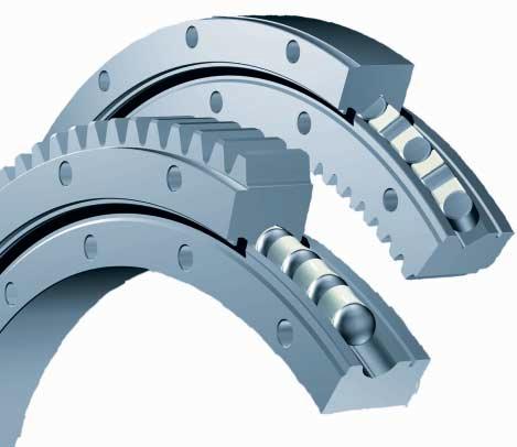
11 SLEWING RING CHARACTERISTICS, APPLICATIONS Slewing rings are large-sized bearings which are able to accommodate combined load, i.e. axial, radial loads and tilting moment. They are usually provided with holes for fixing bolts, internal or external gear, lubrication holes and seals, which allow a compact and economical arrangement. They often enable elimination of many components necessary in the classical bearing arrangement. PSL slewing rings have proven ability in the following applications - construction, mobile and pillar cranes, - shovel, digging-wheel excavators, - revolving grabs and winches, - graders, - logging industry machines, - loaders, vehicles for waste removal, hydraulic grippers, - axles and undercarriages, - assembly and access platforms, - robots, manipulators and positioners, - machine tools, - special equipment (rescue vehicles, aerials, feller bunchers and tunnel machines, drilling equipment, wind-power plants, cleaning and bottle filling machines). Compactness, accuracy and smooth operation with relatively high rigidity, together with simple mounting and reliability in operation are qualities that allow the use of these bearings in all industrial branches.
Precision Ball Screw/Spline
 58-2E Models BNS-A, BNS, NS-A and NS Seal Outer ring Shim plate Seal Spline nut Seal Collar Shim plate Seal End cap Ball Outer ring Ball screw nut Outer ring Ball Retainer Retainer Outer ring Point of
Identification Number
 Identification Number The specification of Micro Linear Way LWL is specified by the identification number, which consists of a model code, a size, a part code, a preload symbol, a classification symbol,
XR Series. Introduction. Design Features. Availability. Applications
 Kaydon Bearings Slewing Ring Bearings Catalog 390 Introduction The consists of Kaydon cross roller bearings. They provide a high degree of stiffness and low rotational torque within a minimal envelope.
The basic dynamic load rating C is a statistical number and it is based on 90% of the bearings surviving 50 km of travel carrying the full load.
 Technical data Load Rating & Life Under normal conditions, the linear rail system can be damaged by metal fatigue as the result of repeated stress. The repeated stress causes flaking of the raceways and
S.C. Rulmenti S.A. Barlad Romania Republicii Street No
 SELECTION OF BEARING SIZE Basic load ratings The size of a bearing is selected considering the load in the used rolling bearing and also depends on the operational rating life and prescribed operating
+ + = integer (13-15) πm. z 2 z 2 θ 1. Fig Constrained Gear System Fig Constrained Gear System Containing a Rack
 πm. z 2 z 2 θ 1. Fig Constrained Gear System Fig Constrained Gear System Containing a Rack") Figure 13-8 shows a constrained gear system in which a rack is meshed. The heavy line in Figure 13-8 corresponds to the belt in Figure 13-7. If the length of the belt cannot be evenly divided by circular
Figure 13-8 shows a constrained gear system in which a rack is meshed. The heavy line in Figure 13-8 corresponds to the belt in Figure 13-7. If the length of the belt cannot be evenly divided by circular
Bearing Internal Clearance and Preload
 . Bearing Internal Clearance and Preload. Bearing internal clearance Bearing internal clearance is the amount of internal free movement before mounting. As shown in Fig.., when either the inner ring or
AE / AER Series. AER Series
 AE / AER Series Characteristic Highlights True helical gear design Precision helical gearing increases tooth to tooth contact ratio by over % vs spur gearing. The helix angle produces smooth and quiet
Planetary Screw Assemblies PLSA
 Planetary Screw Assemblies PLSA Ernst-Sachs-Straße 100 97424 Schweinfurt Tel. +49 9721 937-0 Fax +49 9721 937-275 www.boschrexroth.com Catalog "Planetary Screw Assemblies PLSA" R310XX 3308 (2014.01) Dear
SNL plummer block housings, 2, 3, 5 and 6 series Other bearing housings Large SNL plummer block housings
 Bearing housings SNL plummer block housings, 2, 3, 5 and 6 series... 1033 Other bearing housings... 1058 Large SNL plummer block housings... 1058 SONL plummer block housings... 1059 SDG plummer block housings...
 Identification The of -Lube Linear Roller Way Super MX is identified by the identification, which consists of model code, size, part code, material symbol preload symbol, classification symbol, interchangeable
Prediction of Life of Rolling Pairs in Cycloidal Gear Design
 Mechanics and Mechanical Engineering Vol. 9, No. 2 (2005) 77 88 c Technical University of Lodz Prediction of Life of Rolling Pairs in Cycloidal Gear Design Manfred Chmurawa Silesian University of Technology,
second PLSA line R310EN 3308 ( )
") 01_1 Planetary st Headline_36 Screw Assemblies pt/14.4 mm second PLSA line R310EN 3308 (2011-09) 2 Planetary Screw Assemblies PLSA Planetary Screw Assemblies PLSA Product Overview 3 Nuts, Screws, Screw
01_1 Planetary st Headline_36 Screw Assemblies pt/14.4 mm second PLSA line R310EN 3308 (2011-09) 2 Planetary Screw Assemblies PLSA Planetary Screw Assemblies PLSA Product Overview 3 Nuts, Screws, Screw
BEARINGS Pillow Blocks
 The bearing size is usually selected according to the required bearing life and reliability under a specified type of load charged on the bearing. The load applied to the bearing operating under a static
Stress Analysis Lecture 3 ME 276 Spring Dr./ Ahmed Mohamed Nagib Elmekawy
 Stress Analysis Lecture 3 ME 276 Spring 2017-2018 Dr./ Ahmed Mohamed Nagib Elmekawy Axial Stress 2 Beam under the action of two tensile forces 3 Beam under the action of two tensile forces 4 Shear Stress
Classic Mini ( ) Transmission Bearing Load Estimates During Service
 Transmission Bearing Load Estimates During Service") Classic Mini (1959 2000) Transmission Bearing Load Estimates During Service Purpose The removal and replacement of the nuts at the ends of the first and third motion shafts in the classic Mini transmission
Classic Mini (1959 2000) Transmission Bearing Load Estimates During Service Purpose The removal and replacement of the nuts at the ends of the first and third motion shafts in the classic Mini transmission
C-Lube Linear Way ML Linear Way L ML LWL
 -Lube Linear ay ML Linear ay L MLLL -Lube Maintenance ree Series -Lube Linear ay ML ML long term maintenance free supported! The aquamarine end plate is the symbol of maintenance free. Identification umber
Helical Gears n A Textbook of Machine Design
 1066 n A Textbook of Machine Design C H A P T E R 9 Helical Gears 1. Introduction.. Terms used in Helical Gears. 3. Face Width of Helical Gears. 4. Formative or Equivalent Number of Teeth for Helical Gears.
C-Lube Linear Way ML ML MLF
 Maintenance ree & U.S. PTTD C-Lube Linear ay Variation of C-Lube Linear ay Shape Length of slide unit Model code C-Lube Linear ay is a linear motion rolling guide, incorporating the C-Lube as a components
Application nr. 7 (Connections) Strength of bolted connections to EN (Eurocode 3, Part 1.8)
 Strength of bolted connections to EN (Eurocode 3, Part 1.8)") Application nr. 7 (Connections) Strength of bolted connections to EN 1993-1-8 (Eurocode 3, Part 1.8) PART 1: Bolted shear connection (Category A bearing type, to EN1993-1-8) Structural element Tension
Application nr. 7 (Connections) Strength of bolted connections to EN 1993-1-8 (Eurocode 3, Part 1.8) PART 1: Bolted shear connection (Category A bearing type, to EN1993-1-8) Structural element Tension
ER2 Short-head Electric Chain Hoist
 O/M NO.SHER2-0903-CE-00 ER2 Short-head Electric Chain Hoist (250kg to 5t) Operation Manual (SHER2M/SHER2SG/SHER2SP) Introduction The KITO Short-head Electric Chain Hoist is intended for effective use in
R-Plus System Frontespizio_R_PlusSystem.indd 1 11/06/ :32:02
 R-Plus System R-Plus System R-Plus system R-Plus system description Fig. R-Plus system R-Plus System is Rollon s series of rack & pinion driven actuators. Rollon R-Plus System series linear units are designed
Cam Roller Guides. The Drive and Control Company. Service Automation. Electric Drives and Controls. Linear Motion and Assembly Technologies
 Industrial Hydraulics Electric Drives and Controls Linear Motion and Assembly Technologies Pneumatics Service Automation Mobile Hydraulics Cam Roller Guides The Drive and Control Company Linear Motion
Load Washers. Force. for Forces of 7, kn. F z. Type 9001A A 9081B, 9091B
 Force Load Washers for Forces of 7,5... 1 200 kn Type 9001A... 9071A 9081B, 9091B 1-component force sensor for measuring dynamic and quasistatic forces in z direction. F z Calibrated measuring range 100
Planetary Screw Assemblies PLSA
 Planetary Screw Assemblies PLSA R310EN 3308 (2011-09) The Drive & Control Company C/ Centauro, 13 Área Empresarial Las Cubiertas 28971-Griñón (Madrid) T. 0034 91 126 6627 info@diversiatec.com www.diversiatec.com
Investigation of basic elements loading and tension of heavy hydraulic presses for metallurgical production
 Investigation of basic elements loading and tension of heavy hydraulic presses for metallurgical production Ganush V. I. National metallurgical academe of Ukraine Ostroverhov N. P., Sultan A. V., Dzichkovky
Course: Technology II Training course topic: Metrology
 Department of machining, process planning and metrology ver.2017-01 Following problems and tasks will be solved during the first two weeks of the training courses of Technology II. Detailed information
Linear guide drives. Synchronous shafts The use of synchronous shafts enables several linear axes to be operated with one drive.
 Linear guide drives Drive concept The linear guides are driven via the hollow shaft in the drive head. The drive head is used to directly install a motor or alternatively (in connection with a center shaft)
Rotary modules.
 Rotary modules www.comoso.com www.comoso.com Rotary modules ROTARY MODULES Series Size Page Rotary modules RM swivel unit 156 RM 08 160 RM 10 162 RM 12 164 RM 15 168 RM 21 172 RM rotor 176 RM 50 180 RM
Miniature (SEB Type) Tapped-Hole rail Types: Slide guides with clearance holes are standard and tapped holes are available upon request.
 Tapped-Hole rail Types: Slide guides with clearance holes are standard and tapped holes are available upon request.") Miniature (SE Type) The SE type slide guide is a linear motion bearing in which the ball elements roll along two tracking grooves. This is the smallest and lightest slide guide series offered by Nippon
Miniature (SE Type) The SE type slide guide is a linear motion bearing in which the ball elements roll along two tracking grooves. This is the smallest and lightest slide guide series offered by Nippon
 Identification The specification of C-Lube Linear ay is identified by the identification, which consists of a model code, a size, a part code, a material code, a preload symbol, a classification symbol,
PRECISION GEARS Spur Gears
 Spur Gears Description Symbol Unit Equation Normal Module m n Transverse Module m t = m n Normal Pressure Angle a n degrees = 2 Transverse Pressure Angle a t degrees = a n Number of Teeth z Profile Shift
Lesson of Mechanics and Machines done in the 5th A-M, by the teacher Pietro Calicchio. THE GEARS CYLINDRICAL STRAIGHT TEETH GEARS
 MESA PROJECT Lesson of Mechanics and Machines done in the 5th A-M, 2012-2013 by the teacher Pietro Calicchio. THE GEARS To transmit high power are usually used gear wheels. In this case, the transmission
Miniature Slide Guide Series with Retained Ball now Offers Complete Selection
 Miniature Slide Guide Series with Retained Ball now Offers Complete Selection Wide type of Miniature Slide Guide, providing greater allowable moment, is now available with retained ball structure. Due
P R E C I S I O N G E A R S Spur Gears
 Spur Gears Description Symbol Unit Equation Normal Module m n Transverse Module m t = m n Normal Pressure Angle α n degrees = 2 Transverse Pressure Angle α t degrees = α n Number of Teeth z Profile Shift
Dimensions of propulsion shafts and their permissible torsional vibration stresses
 (Feb 2005) (orr.1 Mar 2012) (orr.2 Nov 2012) Dimensions of propulsion shafts and their permissible torsional vibration stresses.1 Scope This UR applies to propulsion shafts such as intermediate and propeller
HPG xxx 030 C1 C2 C3. High performance angle gearboxes. Output. Input. Drawings. C with option motor flange. View x. Centering View y.
 HPG 030 1 2 3 Input Output 1 View M6 ( deep) 0 Ø4 H (2.2 deep) 18.0 M6 ( deep) 0 2 3 M6 ( deep) 2 13.0 4 2.0 18.0 24.0 M Ø12 k6 6 M6 ( deep) M6 ( deep) 3 Eample HPG 030 2 with option motor flange 0 M6
ENGINEERING INFORMATION TABLE OF CONTENTS SHAFT AND HOUSING FITS LUBRICATION LIFE AND LOAD RATINGS RADIAL CLEARANCE CHART
 ENGINEERING INFORMATION TABLE OF CONTENTS ENGINEERING INFORMATION SHAFT AND HOUSING FITS LUBRICATION LIFE AND LOAD RATINGS RADIAL CLEARANCE CHART SHAFT AND HOUSING FITS FOR METRIC RADIAL BALL AND ROLLER
Heat Transfer Analysis of Machine Tool Main Spindle
 Technical Paper Heat Transfer Analysis of Machine Tool Main Spindle oshimitsu HIRASAWA Yukimitsu YAMAMOTO CAE analysis is very useful for shortening development time and reducing the need for development
Lecture Slides. Chapter 14. Spur and Helical Gears
 Lecture Slides Chapter 14 Spur and Helical Gears The McGraw-Hill Companies 2012 Chapter Outline Cantilever Beam Model of Bending Stress in Gear Tooth Fig. 14 1 Lewis Equation Lewis Equation Lewis Form
Design against fluctuating load
 Design against fluctuating load In many applications, the force acting on the spring is not constants but varies in magnitude with time. The valve springs of automotive engine subjected to millions of
CONNECTION DESIGN. Connections must be designed at the strength limit state
 CONNECTION DESIGN Connections must be designed at the strength limit state Average of the factored force effect at the connection and the force effect in the member at the same point At least 75% of the
SOLUTION (17.3) Known: A simply supported steel shaft is connected to an electric motor with a flexible coupling.
 Known: A simply supported steel shaft is connected to an electric motor with a flexible coupling.") SOLUTION (17.3) Known: A simply supported steel shaft is connected to an electric motor with a flexible coupling. Find: Determine the value of the critical speed of rotation for the shaft. Schematic and
SOLUTION (17.3) Known: A simply supported steel shaft is connected to an electric motor with a flexible coupling. Find: Determine the value of the critical speed of rotation for the shaft. Schematic and
ATF 90G-4. Operating, Service and Maintenance Manual. Vehicle identification no: WFN4 RUL R
 Operating, Service and Maintenance Manual ATF 90G-4 Vehicle identification no: WFN4 RUL R5 72045 Manufacturer FAUN GmbH Postfach 10 01 08 D - 91205 Lauf a. d. Pegnitz Tel: (09123) 185-0 Fax: (09123) 7
Product description. Compact Modules. Characteristic features. Further highlights
 4 Compact Modules Product description Characteristic features Five fine-tuned sizes based on a compact precision aluminum profile with two integrated pre-tensioned ball rail systems Identical external
870. Vibrational analysis of planetary gear trains by finite element method
 870. Vibrational analysis of planetary gear trains by finite element method Pei-Yu Wang 1, Xuan-Long Cai 2 Department of Mechanical Design Engineering, National Formosa University Yun-Lin County, 632,
Vane Type Rotary Actuators Series Variations
 Vane Type Rotary Actuators Series Variations Vane Type Exterior CRB Series 0,, 0,, CRBU Series 0,, 0,, CRB Series, 6, 80, Has a compact body with exterior dimensions that do not change regardless of the
VIBRATION ANALYSIS OF TIE-ROD/TIE-BOLT ROTORS USING FEM
 VIBRATION ANALYSIS OF TIE-ROD/TIE-BOLT ROTORS USING FEM J. E. Jam, F. Meisami Composite Materials and Technology Center Tehran, IRAN jejaam@gmail.com N. G. Nia Iran Polymer & Petrochemical Institute, Tehran,
12/25/ :27 PM. Chapter 14. Spur and Helical Gears. Mohammad Suliman Abuhaiba, Ph.D., PE
 Chapter 14 Spur and Helical Gears 1 2 The Lewis Bending Equation Equation to estimate bending stress in gear teeth in which tooth form entered into the formulation: 3 The Lewis Bending Equation Assume
A 954 C HD. Technical Description Hydraulic Excavator. Machine for Industrial Applications
 Technical Description Hydraulic Excavator A 95 C HD litronic` Machine for Industrial Applications Operating Weight 165,800 170,0 lb Engine Output 36 hp (0 kw) Technical Data Engine Rating per ISO 99 0
Overview. Dry Friction Wedges Flatbelts Screws Bearings Rolling Resistance
 Friction Chapter 8 Overview Dry Friction Wedges Flatbelts Screws Bearings Rolling Resistance Dry Friction Friction is defined as a force of resistance acting on a body which prevents slipping of the body
Theory & Practice of Rotor Dynamics Prof. Rajiv Tiwari Department of Mechanical Engineering Indian Institute of Technology Guwahati
 Theory & Practice of Rotor Dynamics Prof. Rajiv Tiwari Department of Mechanical Engineering Indian Institute of Technology Guwahati Module - 8 Balancing Lecture - 1 Introduce To Rigid Rotor Balancing Till
Research Article Dynamic Carrying Capacity Analysis of Double-Row Four-Point Contact Ball Slewing Bearing
 Mathematical Problems in Engineering Volume 215, Article ID 8598, 7 pages http://dx.doi.org/1.1155/215/8598 Research Article Dynamic Carrying Capacity Analysis of Double-Row Four-Point Contact Ball Slewing
ZF Maschinenantriebe GmbH Industrial Drives. Planetary gearboxes Economy Series for Servomotors
 ZF Maschinenantriebe GmbH Industrial rives Planetary gearboxes Economy Series for Servomotors 2 ZF-uoplan 2K Two-speed Gearboxes ZF-Ecolift Elevator Gearboxes ZF-Servoplan G ompact Gearbox ZF-Tiratron
CTV series CHARACTERISTICS LINEAR UNITS
 CTV series CHARACTERISTICS The CTV series describes s with a precision ball screw drive and two parallel, integrated, Zerobacklash rail guides. Compact dimensions allow high performance features such as,
Load Washers. Force kn until kn. Type 9101A A
 Force Load Washers 0... 20 kn until 0... 700 kn Type 9101A... 9107A Force sensor for measuring quasistatic and dynamic forces in industrial monitoring tasks. F z The force sensors are delivered uncalibrated
Mitigation of Diesel Generator Vibrations in Nuclear Applications Antti Kangasperko. FSD3020xxx-x_01-00
 Mitigation of Diesel Generator Vibrations in Nuclear Applications Antti Kangasperko FSD3020xxx-x_01-00 1 Content Introduction Vibration problems in EDGs Sources of excitation 2 Introduction Goal of this
Chapter 11. Bearing Types. Bearing Load. The Reliability Goal. Selection of Tapered Roller Bearings
 Chapter 11 Rolling Contact Bearing Bearing Types Bearing Life Bearing Load Bearing Survival The Reliability Goal Selection of Ball and Straight Roller Bearings Selection of Tapered Roller Bearings 1 Introduction
POLE WHEELS. Where the shaft is very large a cost-effective alternative is to add a pole band (see following section).
.") A pole wheel on the target shaft is required when using contactless sensors to generate a signal. Often an existing gear wheel can be used but where none is present a special gear, slotted or holed disk
A pole wheel on the target shaft is required when using contactless sensors to generate a signal. Often an existing gear wheel can be used but where none is present a special gear, slotted or holed disk
Questionaire Gears from Plastic:
 Wolf Kunststoff-Gleitlager GmbH Heisenbergstr. 63-65 Industriegebiet II 50169 Kerpen - Türnich Deutschland Telefon: +49 2237 9749-0 Telefax: +49 2237 9749-20 Email: info@zedex.de Internet: www.zedex.de
Product Description. Further highlights. Outstanding features. 4 Bosch Rexroth Corporation Miniature Linear Modules R310A 2418 (2009.
 4 Bosch Rexroth orporation Miniature Linear Modules R310A 2418 (2009.05) Product Description Outstanding features Rexroth Miniature Linear Modules are precise, ready-to-install linear motion systems that
New Representation of Bearings in LS-DYNA
 13 th International LS-DYNA Users Conference Session: Aerospace New Representation of Bearings in LS-DYNA Kelly S. Carney Samuel A. Howard NASA Glenn Research Center, Cleveland, OH 44135 Brad A. Miller
UNI EN ISO 9001:2008 UNI EN ISO 14001:2004 BS OHSAS 18001:2007 EC DIRECTIVE 2014/34/EU (ATEX) CERTIFIED MANAGEMENT SYSTEM
 CERTIFIED MANAGEMENT SYSTEM") EN ISM-BSM CERTIFIED Technology Made in Italy Since 1955 the Varvel Group has been making speed reducers and variators for light industry applications. Reliable partner in power transmission equipment
EN ISM-BSM CERTIFIED Technology Made in Italy Since 1955 the Varvel Group has been making speed reducers and variators for light industry applications. Reliable partner in power transmission equipment
Lightweight. Geislinger Gesilco
 Lightweight Geislinger Gesilco The Geislinger Gesilco product range is based on more than 20 years of experience in developing fibre composite couplings and shafts. The maintenance-free composite membranes
Note: Read section (12-1) objective of this chapter (Page 532)
 objective of this chapter (Page 532)") References: Machine Elements in Mechanical Design by Robert L. Mott, P.E. (Chapter 12 Note: Read section (12-1 objective of this chapter (Page 532 Page 1 of 29 Shaft Design Procedure (Sec. 12-2, Page 532
References: Machine Elements in Mechanical Design by Robert L. Mott, P.E. (Chapter 12 Note: Read section (12-1 objective of this chapter (Page 532 Page 1 of 29 Shaft Design Procedure (Sec. 12-2, Page 532
The SynchMotion. Retainer
 106 G99TE13-0809 Linear Guideways QE Series 2-9 QE Type Quiet Linear Guideway, with SynchMotion TM Technology The development of HIIN-QE linear guideway is based on a four-row circular-arc contact. The
( ) 5. Bearing internal load distribution and displacement. 5.1 Bearing internal load distribution
 5. Bearing internal load distribution and displacement. 5.1 Bearing internal load distribution") 5. internal load distribution and displacement 5. internal load distribution This section will begin by examing the effect of a radial load F r and an axial load F a applied on a single-row bearing with
5. internal load distribution and displacement 5. internal load distribution This section will begin by examing the effect of a radial load F r and an axial load F a applied on a single-row bearing with
MEMS Project 2 Assignment. Design of a Shaft to Transmit Torque Between Two Pulleys
 MEMS 029 Project 2 Assignment Design of a Shaft to Transmit Torque Between Two Pulleys Date: February 5, 206 Instructor: Dr. Stephen Ludwick Product Definition Shafts are incredibly important in order
Thermohydrodynamic Lubrication Characteristics of High-Speed Tilting Pad Journal Bearings
 Thermohydrodynamic Lubrication Characteristics of High-Speed Tilting Pad Journal Bearings OGATA Hideki : Manager, Vibration Engineering & Tribology Department, Research Laboratory, Corporate Research &
1 Input data. Profis Anchor Company: Specifier: Address: Phone I Fax: Page: Project: Sub-Project I Pos. No.
 1 Specifier's comments: Check of Existing Base plate (B6)- According to max. forces on Node No. 11979, LC 1.4(D.L.+WX) 1 Input data Anchor type and diameter: HIT-HY 200 + HIT-V-F (8.8) M27 Seismic/Filling
1 Input data. Profis Anchor Company: Specifier: Address: Phone I Fax: Page: Project: Sub-Project I Pos. No.
 1 Specifier's comments: Design of Typical Baseplate B1 according to Max. forces in Node No. (5984), LC19 (1.2D+1.6S+0.8WY CASE B) 1 Input data Anchor type and diameter: HIT-HY 200 + HIT-V (8.8) M24 Seismic/Filling
Automated Spur Gear Designing Using MATLAB
 Kalpa Publications in Engineering Volume 1, 2017, Pages 493 498 ICRISET2017. International Conference on Research and Innovations in Science, Engineering &Technology. Selected Papers in Engineering Automated
Lexium integrated drives
 Presentation GBX planetary gearbox Presentation In many cases the axis controller requires the use of a planetary gearbox for adjustment of speed of rotation and torque; the accuracy required by the application
Entrance exam Master Course
 - 1 - Guidelines for completion of test: On each page, fill in your name and your application code Each question has four answers while only one answer is correct. o Marked correct answer means 4 points
5. STRESS CONCENTRATIONS. and strains in shafts apply only to solid and hollow circular shafts while they are in the
 5. STRESS CONCENTRATIONS So far in this thesis, most of the formulas we have seen to calculate the stresses and strains in shafts apply only to solid and hollow circular shafts while they are in the elastic
Members Subjected to Torsional Loads
 Members Subjected to Torsional Loads Torsion of circular shafts Definition of Torsion: Consider a shaft rigidly clamped at one end and twisted at the other end by a torque T = F.d applied in a plane perpendicular
FLENDER drives Fundamental Principles of Mechanical Engineering
 FLENDER drives Fundamental Principles of Mechanical Engineering Technical Handbook Technical Drawings Standardization 2 Physics 3 Mathematics / Geometry 4 Mechanics / Strength of Materials 5 Hydraulics
TABLE OF CONTENT Scope 2 Alignment Systems and Procedures 2 Balancing 8 Lubrication System 10 Preservation of Spare Parts 12
 Page : 1 of 21 Project Engineering Standard www.klmtechgroup.com KLM Technology #03-12 Block Aronia, Jalan Sri Perkasa 2 Taman Tampoi Utama 81200 Johor Bahru Malaysia TABLE OF CONTENT Scope 2 Alignment
Shaft Locking Devices
 External Shaft ocking evice Available sizes: Page # S 900 Self-centering Exceptional concentricity Suitable for hollow shafts Axial hub position fixe uring clamping etric 14mm to 240mm arger sizes on request
LINE TECH Linear Modules. Ready to built-in linear modules with drive
 Ready to built-in linear modules with drive Anodized profile, produced in extrusion molding method Linear rail guiding system (LM3 LM5) Actuation by ball screw, high-helix lead _ screw or toothed belt
Nonlinear Rolling Element Bearings in MADYN 2000 Version 4.3
 - 1 - Nonlinear Rolling Element Bearings in MADYN 2000 Version 4.3 In version 4.3 nonlinear rolling element bearings can be considered for transient analyses. The nonlinear forces are calculated with a
CALIBRATION MECHANISM FOR INFRARED SPACE TELESCOPE. Patrice Kerhousse
 CALIBRATION MECHANISM FOR INFRARED SPACE TELESCOPE Patrice Kerhousse Alcatel space industries Boulevard du Midi, BP 99-06156 Cannes la Bocca Cedex Telephone : 33-(0)4-92-92-72-38 / Fax : 33-(0)4-92-92--20
4. SHAFTS. A shaft is an element used to transmit power and torque, and it can support
 4. SHAFTS A shaft is an element used to transmit power and torque, and it can support reverse bending (fatigue). Most shafts have circular cross sections, either solid or tubular. The difference between
ilearnalignment Alignment Training Subjects
 ilearnalignment Alignment Training Subjects The following is a list of the subjects covered in the ilearnalignment training system. The complete detail is shown. Alignment Fundamentals - An Introduction
Levers. 558 A Textbook of Machine Design
 558 A Textbook of Machine Design C H A P T E R 15 Levers 1. Introduction.. Application of Levers in Engineering Practice.. Design of a Lever. 4. Hand Lever. 5. Foot Lever. 6. Cranked Lever. 7. Lever for
Identification system for short product names. Changes/amendments at a glance. 2 Bosch Rexroth AG OBB omega modules R ( )
") Omega Modules OBB 2 OBB omega modules R9990079 (206-05) Identification system for short product names Short product name Example: O B B - 085 - N N - System = Omega module Guideway = Ball Rail System Drive
Omega Modules OBB 2 OBB omega modules R9990079 (206-05) Identification system for short product names Short product name Example: O B B - 085 - N N - System = Omega module Guideway = Ball Rail System Drive
3 Hours/100 Marks Seat No.
 *17304* 17304 14115 3 Hours/100 Marks Seat No. Instructions : (1) All questions are compulsory. (2) Illustrate your answers with neat sketches wherever necessary. (3) Figures to the right indicate full
SlimLine Sensors (SLS)
") Force SlimLine Sensors (SLS) Measurement of Dynamic and Quasistatic Forces, 0 3 kn up to 0 80 kn Quartz sensor series with extremely flat design for measuring dynamic and quasistatic forces. High resolution,
Force SlimLine Sensors (SLS) Measurement of Dynamic and Quasistatic Forces, 0 3 kn up to 0 80 kn Quartz sensor series with extremely flat design for measuring dynamic and quasistatic forces. High resolution,
T20WN. Data Sheet. Torque transducers. Special features. Installation example with bellows couplings. B en
 T20WN Torque transducers Data Sheet Special features - Nominal (rated) torques 0.1 N m, 0.2 N m, 0. N m, 1 N m, 2 N m, N m, 10 N m, 20 N m, 0 N m, 100 N m, 200 N m - Accuracy class: 0.2 - Contactless transmission
H a r m o n i c P l a n e t a r y
 H a r m o n i c P l a n e t a r y HPG Series Planetary Gearhead Total Motion Control P r e c i s i o n G e a r i n g & M o t i o n C o n t r o l Harmonic Drive LLC is the world s largest manufacturer of
Example 4: Design of a Rigid Column Bracket (Bolted)
") Worked Example 4: Design of a Rigid Column Bracket (Bolted) Example 4: Design of a Rigid Column Bracket (Bolted) Page : 1 Example 4: Design of a Rigid Column Bracket (Bolted) Determine the size of the
Worked Example 4: Design of a Rigid Column Bracket (Bolted) Example 4: Design of a Rigid Column Bracket (Bolted) Page : 1 Example 4: Design of a Rigid Column Bracket (Bolted) Determine the size of the
The University of Melbourne Engineering Mechanics
 The University of Melbourne 436-291 Engineering Mechanics Tutorial Four Poisson s Ratio and Axial Loading Part A (Introductory) 1. (Problem 9-22 from Hibbeler - Statics and Mechanics of Materials) A short
Maintenance Free C-Sleeve Linear Way ML ME MH MUL
 Maintenance ree C-Sleeve Linear ay M M MUL CAT-A e aim to be a Technology-Developing company taking customer-need as primary source for the development. ith our original technologies and creativities,
EDEXCEL NATIONAL CERTIFICATE/DIPLOMA FURTHER MECHANICAL PRINCIPLES AND APPLICATIONS UNIT 11 - NQF LEVEL 3 OUTCOME 4 - LIFTING MACHINES
 EDEXCEL NATIONAL CERTIFICATE/DIPLOMA FURTHER MECHANICAL PRINCIPLES AND APPLICATIONS UNIT 11 - NQF LEVEL 3 OUTCOME 4 - LIFTING MACHINES CONTENT Be able to determine the operating characteristics of lifting
STATIC AND DYNAMIC ANALYSIS OF A PUMP IMPELLER WITH A BALANCING DEVICE PART I: STATIC ANALYSIS
 Int. J. of Applied Mechanics and Engineering, 04, vol.9, No.3, pp.609-69 DOI: 0.478/ijame-04-004 STATIC AND DYNAMIC ANALYSIS OF A PUMP IMPELLER WITH A BALANCING DEVICE PART I: STATIC ANALYSIS C. KUNDERA
Not all thin-section bearings are created equal. KAYDON new capacity calculations. Robert Roos, Scott Hansen
 Not all thin-section bearings are created equal KAYDON new capacity calculations Robert Roos, Scott Hansen A white paper from KAYDON Bearings Division Table of Contents Abstract... pg. Introduction...
BD-04a: Check Machine Geometry and Lost Motion
 Page 1 of 14 BD-04a: Check Machine Geometry and Lost Motion SAFETY FIRST o Follow all Caterpillar facility safety standards when performing this task. o A hoist will be necessary for moving the cube or
MODULE F: SIMPLE CONNECTIONS
 MODULE F: SIMPLE CONNECTIONS This module of CIE 428 covers the following subjects Connector characterization Failure modes of bolted shear connections Detailing of bolted connections Bolts: common and
Selection table for guided systems (crank driven)
") Selection table for guided systems (crank driven) One mass shaker brute-force system One mass shaker natural frequency system Two mass shaker fast-runner system with reaction force-compensation Single
Selection table for guided systems (crank driven) One mass shaker brute-force system One mass shaker natural frequency system Two mass shaker fast-runner system with reaction force-compensation Single
APEX DYNAMICS, INC. Staianless
 APE DYNAMICS, INC. HIGH PRECISION HIGH SPEED PLANETARY GEARBOES AF / AFR Series Staianless High precision high speed planetary gearboxes AF / AFR series Apex Dynamics, Inc. is the world s most productive