Identification system for short product names. Changes/amendments at a glance. 2 Bosch Rexroth AG OBB omega modules R ( )
|
|
|
- Cory Peters
- 5 years ago
- Views:
Transcription

1 Omega Modules OBB
2 2 OBB omega modules R (206-05) Identification system for short product names Short product name Example: O B B N N - System = Omega module Guideway = Ball Rail System Drive = Toothed Belt Drive Size = 055 / 085 / 20 Version = Standard model Generation = Product generation Short product name Using the short product name, Rexroth linear axes can be identified according to their product family, size, version and product generation. Changes/amendments at a glance Catalog structure New catalog number New product designation Revised dimensional drawings "Delivery form" additional chapter "Calculation" expanded chapter "EasyHandling" additional chapter Additional chapters "Switches", "Extensions" and "Distributors" "Power cable chains" chapter deleted Technical modifications Increase of the dynamic load capacities and moments Revised table structure of the tech. data tables and drive data Integration of new motor types (MSM) Technical details of clamping element (LKPS) Chapters "Operating conditions" and "Lubrication" revised "Parameterization" chapter amended Order example Query sheet
3 R (206-05) OBB omega modules Omega modules OBB Product overview Product description Load ratings and sizes 6 Structural design 7 Delivery form 9 Technical data General technical data Drive data 0 Deflection 2 Deflection charts Calculations Calculation principles Mounting orientation HORIZONTAL 20 Mounting orientation VERTICAL 2 Calculation example Mounting orientation HORIZONTAL 26 Mounting orientation VERTICAL 28 Configuration and ordering OBB-055 Configuration and ordering 0 Dimensions 2 OBB-085 Configuration and ordering Dimensions 6 OBB-20 Configuration and ordering 8 Dimensions 0 Attachments and accessories Switch mounting frame moves (carriage fixed) 2 Switch mounting carriage moves (frame fixed) Cable duct 6 Socket and plug 7 Switches 52 Extension pieces 56 Distributors 60 Extensions for passive distributors 62 Combination examples 6 Mounting 66 Carriage with clamping element Carriage 70 Clamping element (LKPS) 70 Attachment of additional devices End plate for attachment 7 Shock absorber 72 IndraDyn S servo motors MSK 7 IndraDyn S servo motors MSM 76 EasyHandling 78 Service and information Operating conditions Normal operating conditions 82 Design notes 82 Required and supplementary documentation 82 Lubrication 8 Documentation 8 Parameterization 8 Further information 85 Ordering example OBB-085 Configuration and ordering 86 Inquiry/order form 88


 or angular planetary gearbox (WPG) with different gear ratios Pneumatic clamping elements (optional) Extensive range of accessories available Sectors: Handling and assembly Electronics and")

4 OBB omega modules R (206-05) Product overview Product description Omega modules (OBB) with ball rail systems and toothed belt drive for travel speeds up to 5.0 m/s. Omega modules are ready-to-install linear axes for any desired mounting orientation in freely configurable lengths up to 5500 mm. Due to the design, Omega modules are particularly well suited for applications where the frame enters the working area. Characteristic features: Extremely compact precision aluminum profile with integrated Rexroth ball rail system for optimal travel Carriage with one-point lubrication With locating holes in the carriage and on the end plates Driven with toothed belts for high dynamics and high travel speed Mountable switches Available complete with motor, controller and control unit With planetary gearbox (PG) or angular planetary gearbox (WPG) with different gear ratios Pneumatic clamping elements (optional) Extensive range of accessories available Sectors: Handling and assembly Electronics and semiconductor industry Automotive suppliers and OEMs Robotics and automation Special-purpose machines Packaging technology Building services Plastics processing Textile industry Application areas: Pick and place Handling systems Component assembly systems, palletizers Feed units for machine tools Testing and analysis systems Feed units in transfer lines Load shifters For mounting, maintenance and start-up, see the Instructions. Mounting option Fastening thread and locating holes Versatile mounting options are provided by the fastening threads and locating holes on the two end plates of the frame. Easy mounting thanks to locating holes in the carriage


")

: a carriage with planetary")
5 R (206-05) OBB omega modules 5 Frame HK moves OBB as a vertical axis Installation case: Frame moves (carriage fixed) OBB as a horizontal axis Installation case: Frame moves (carriage fixed) Carriage TT moves OBB as a horizontal axis Installation case: Carriage moves (frame mounted) On request: OBB as horizontal axis with two carriages Installation case: Carriages move independently of each other (frame fixed). Representation (example): a carriage with planetary gearbox, a carriage with angular gear.
6 6 OBB omega modules R (206-05) Product overview Load ratings and sizes Note on dynamic load ratings and torques: B Determination of the dynamic load ratings and torques is based on a total travel of 00,000 m. Often only 50,000 m of total travel are actually stipulated. For comparison: Multiply values C, M t and M L by a factor of.26. H H A Size Dimensions (mm) Load ratings A/H B H L max C (N) OBB OBB OBB C = dynamic load rating L max = maximum length of the linear motion system Suitable loads (Recommended values based on experience) z z As far as the desired service life is concerned, loads of up to approximately 20 % of the dynamic characteristic values (C, M t, M L ) have proved acceptable. x y C F z M t /M x max M L/M z max x Here the following must not be exceeded: The maximum permissible drive torque The maximum permissible load The maximum permissible travel speed The maximum permissible acceleration y M L /M y max F y C
 8 Clamping hub for motor attachment 9 Angular planetary gearbox (WPG) 0 Motor Planetary gearbox (PG) 2 Mounting flange Version without gear For customer-built motor attachment 2 5 7")
7 R (206-05) OBB omega modules 7 Structural design Design (without switches) Frame 2 Carriage End plate Belt clamp 5 Toothed belt 6 Lube port (at both end faces) 7 Air port (for carriage with clamping element) 8 Clamping hub for motor attachment 9 Angular planetary gearbox (WPG) 0 Motor Planetary gearbox (PG) 2 Mounting flange Version without gear For customer-built motor attachment Version with angular planetary gearbox Version with planetary gearbox 2 0
 5 Control strip on the frame 6 Socket and plug 7 Switch mounting profile 5 6 5 2 7 Carriage moves (frame fixed) Frame 2 Carriage Mechanical switch (with attachments) Proximity switch")
8 8 OBB omega modules R (206-05) Product overview Structural design Attachments Frame moves (carriage fixed) Frame 2 Carriage Mechanical switches (with attachments) Proximity switch (with attachments) 5 Control strip on the frame 6 Socket and plug 7 Switch mounting profile Carriage moves (frame fixed) Frame 2 Carriage Mechanical switch (with attachments) Proximity switch (with attachments) 5 Switching angle (on the carriage) 6 Socket and plug Accessories 8 Shock absorber Shock absorbers are available as accessories and can be ordered separately with the relevant material number (see page 72). 8 8
9 R (206-05) OBB omega modules 9 Delivery form Version Motor attachment Omega modules are delivered completely ready-mounted. In addition to the Omega module itself, the assembly also includes the motor attachment and motor options if they were included in the order. If a combination of motor and motor attachment has been selected, then the attachment of the components is done as shown in the figure which also shows the location of the motor connector. The motor attachment version is selected or defined during the product configuration and is part of the order code. MG0 MG02 MG0 MG0 MG0 Accessories Lubrication Documentation Optional accessories like the cable duct, switch, switching angles and socket with plugs are included as loose parts in the delivery. Omega modules are delivered with initial greasing. Information about lubricants can be found in the section Lubrication. The manual, safety information and a declaration of incorporation required for assembly and maintenance are included with each Omega module.
10 0 OBB omega modules R (206-05) Technical data General technical data Observe the Calculation page 20 section! Size Carriage Dynamic characteristic values Maximum permissible loads L ca C M t M L M x max M y max M z max F y max F z max Clamping element Guideway Version Carriage Holding force (mm) (N) (Nm) (Nm) (Nm) (Nm) (Nm) (N) (N) (N) OBB without with 70 OBB without with 690 OBB without with 200 Drive data Size Gear type i M ) P u ) v ) max M ) Rs Moved part (carriage TT / frame HK) k ) J fix k ) J var k ) J m d Belt type F ) bp F t perm 2) a max (Nm) (mm/rev) (m/s) (Nm) (kgmm 2 ) (kgmm) (mm 2 ) (mm) (N) (N) (m/s 2 ) OBB-055 without TT AT HK PG TT HK TT HK TT HK WPG TT HK TT HK TT HK OBB-085 without TT AT HK PG TT HK TT HK WPG TT HK TT HK OBB-20 without TT AT HK PG TT HK WPG TT HK ) Maximum power that can be transmitted through the engaging teeth that are in the belt pulley. 2) The permissible tensile load of the belt cross section (belt elasticity limit) is specified for better comparability. This value represents the load limit with respect to the plastic deformation and may not be used to determine the maximum permitted drive torque. ) The specified values apply for the relevant combination shown (OBB without gear or OBB with gear) and are shown reduced based on the motor shaft. For information on the use of the values, see section Calculation.
11 R (206-05) OBB omega modules Length Version Mass carriage Mass frame L ad 2) s min ) L max m ca (kg) Clamping element k g fix k g var I y I z (mm) (mm) (mm) without with (kg) (kg/mm) (cm ) (cm ) Drive i= with PG with WPG Drive i= with PG with WPG Drive i= with PG with WPG.08.8 ) Minimum required travel distance to ensure a reliable lubrication distribution, see Operating conditions. For short-stroke applications with travel distances < s min, please ask. 2) The dimension L ad is required for the length calculation (see section Configuration and ordering for the relevant sizes) PG WPG TT HK = planetary gearbox = angular planetary gearbox = carriage = frame Note Values for the gear are not listed in the Technical data tables, as the gear is part of the linear motion system and is already taken into account in the technical values. Mass of the Omega module Weight calculation does not include motor or switch. m s = k g fix + k g var L + m ca k g fix = constant for fixed-length portion of the mass (kg) k g var = constant for the variable-length portion of the mass (kg/mm) L = length of frame (mm) m s = mass of the linear motion system (kg) m ca = mass of the carriage (kg) a max = maximum permissible acceleration C = dynamic load rating d = diameter of belt pulley F bp = maximum belt drive transmission force F t perm = permissible cable pull strength F y max,f z max = maximum permissible load in y- or z-direction I y,i z = planar moment of inertia i = gear ratio k J fix = constant for fixed-length portion of mass moment of inertia k J var = constant for length-variable portion of mass moment of inertia k J m = constant for mass-specific portion of mass moment of inertia L ca = carriage length L ad = additional length L max = maximum length of the linear motion system M t,m L = dynamic load moment M x max,m y max,m z max = maximum permitted torsional moment around the x-, y-, z-axis M L = dynamic longitudinal moment load capacity M t = dynamic torsional moment load capacity M p = maximum permissible drive torque M Rs = frictional torque of system (on the drive journal) m ca = moved mass of carriage s min = minimum required travel distance u = lead constant v max = maximum permissible travel speed
12 2 OBB omega modules R (206-05) Technical data Deflection A special feature of Omega modules is the possibility to mount them by the carriage, which remains stationary while the frame moves. If a force acts on the overhanging frame in the area of the end plate (F) (direction of force transverse to the travel direction X), the frame undergoes a deflection (f) dependent on the length (L ) (distance from the center of the carriage to the end of the frame). When the OBB is used as a vertical axis in a portal, a deflection of the frame occurs due to the acceleration forces of the horizontal axes. This deflection is reversible, i.e. deflection occurs for as long as the acceleration forces are acting. Example Omega module OBB-055: L = 800 mm F = 00 N, force acting in z-direction f =.2 mm L F f
13 R (206-05) OBB omega modules Deflection charts for loads from the z and y directions OBB-055 The following charts apply for a carriage fixed to the mounting base over the entire area (see section Mounting by the carriage on page 66). For larger lengths or loads, please ask. Y X F z Z f (mm) 2 F = 50 N F = 00 N F = 200 N L (mm) Y X Z f (mm) 2 F y F = 50 N F = 00 N F = 200 N L (mm)
14 OBB omega modules R (206-05) Technical data Deflection Deflection charts for loads from the z and y directions OBB-085 The following charts apply for a carriage fixed to the mounting base over the entire area (see section Mounting by the carriage on page 66). For larger lengths or loads, please ask. Y X F z Z f (mm) 2 F = 00 N F = 200 N F = 00 N L (mm) Y X Z f (mm) 2 F y F = 00 N F = 200 N F = 00 N L (mm)
15 R (206-05) OBB omega modules 5 OBB-20 Y X F z Z f (mm) 2 F = 200 N F = 500 N F = 900 N L (mm) Y X Z f (mm) 2 F y F = 200 N F = 500 N F = 900 N L (mm)


16 6 OBB omega modules R (206-05) Calculations Calculation principles The correct dimensioning and assessment of an application requires structured consideration of the drive train as a whole. The basic element of the drive train is the configuration comprising the linear motion system, the transmission element (gear) and the motor which can be ordered in that constellation in the catalog. Drive train Configuration Load Omega module Transmission element Motor Controller Drive train Configuration Load Omega module Transmission element Motor Controller
17 R (206-05) OBB omega modules 7 Maximum permissible load When selecting linear motion systems, it is essential to consider the upper limits for permissible loads and forces, as specified in the section "General technical data" on page 0. The values stated there are system-related. In other words, the upper. limits are determined not only by the load ratings of the bearing points but also include structural design and material-related considerations. Conditions for combined loads: F y F z M x F + F + M y y max z max M + M z x max M + y max M < z max Service life The service life of the rolling bearing points contained in a linear motion system can be calculated using the formulas given below. The rolling bearing point that is relevant to the service life in a linear motion system with toothed belt drive is generally the linear guide. The calculated service life specification for the linear motion system is determined by the service life value of the linear guide. Service life of the linear guide The linear guide of a linear motion system must bear the load, the side torques of the motor attachment / motor and any processing forces. Combined equivalent load on bearing of the linear guide: M x M y M z F comb = F y + F z + C + C + C M t M L M L Nominal life Nominal life in meters: Nominal life in hours: y ( F comb ) L = C 0 5 C L L h = 600 v m z Fz M t/m x max ML/My max M L/M z max F C y x C = dynamic load rating (N) F comb = combined equivalent load on bearing (N) F y = force in y-direction (N) F z = force in z-direction (N) L = nominal life in meters (m) L h = nominal life in hours (h) M L = dynamic longitudinal moment load capacity (Nm) M t = dynamic torsional moment load capacity (Nm) M x = torsional moment about the x-axis (Nm) M y = torsional moment about the y-axis (Nm) M z = torsional moment about the z-axis (Nm) v m = average travel speed (m/s)
18 8 OBB omega modules R (206-05) Calculations General Drive design - Basic principles When calculating the required size of drive, the drive train can be subdivided into the mechanical system and the drive itself. The mechanical system includes the linear motion system component (including transmission element gear), as well as taking into account the load. The electric drive is a motor-controller combination with the appropriate performance data. The sizing or dimensioning of the electric drive is done taking the motor shaft as a reference point. When sizing the drive, limit values must be taken into account as well as basic values. The limit values are to be observed in order to avoid damaging the mechanical components. Drive train Mechanical system Drive Load Linear motion system Transmission element Motor Controller Drive design referred to the motor shaft Technical data and formula symbols for the mechanical system The technical values for the linear motion system already include the relevant gear data and take into account the gear ratio. In other words, the corresponding maximum permissible limits for torque and speed, as well as the underlying friction torque and mass moment of inertia with respect to the motor shaft are reduced and can be taken directly from the tables (see section Drive data ). The following technical data with the associated formula symbols are used when considering the basic mechanical system requirements in the design calculations for sizing the drive. The data listed in the table below can be found in the section Technical data or they are determined using the formulas described on the following pages. Mechanical system Load Linear motion system incl. transmission element gear Weight moment (Nm) M 5) g Frictional torque (Nm) ) M ) Rs Mass moment of inertia (kgm 2 ) J ) t J 2) S Max. permissible travel speed (m/s) v ) max Max. permissible rotary speed (min - ) n ) P Max. permissible drive torque (Nm) M ) P ) Determine the value using the appropriate formula 2) Length-dependent value, determined using the appropriate formula ) Use the value from the table ) Any additional process forces are to be taken into consideration as load moments 5) For vertical mounting position: Determine the value using the appropriate formula
19 R (206-05) OBB omega modules 9 Drive sizing referred to the motor shaft: For the drive configuration, all the relevant design calculation values for the mechanical components contained in the drive train must be determined and be expressed in terms of or reduced to the motor shaft. In other words, for a combination of mechanical components within the drive train, this will result in one value for each of the following: Frictional torque M R Mass moment of inertia J ex Maximum permissible travel speed v mech or maximum permissible rotary speed n mech Maximum permissible drive torque M mech The determination of the values for the mechanics in the drive chain based on the reference point motor shaft differs with regard to the frame moves and carriage moves constellation and is compared with the relevant formula to highlight the differences. For better transparency, the installation orientations horizontal and vertical are addressed and outlined in different sections.
20 20 OBB omega modules R (206-05) Calculations Calculations Mounting orientation HORIZONTAL Installation case Frame moves Carriage moves Frictional torque M R The value for the frictional torque of the linear motion system already includes the friction for an appropriately configured gear unit and has been reduced with reference to the motor shaft. Frictional torque Frame moves M R = M Rs Carriage moves M R = M Rs M R = frictional torque at motor journal M Rs = frictional torque of system (Nm) (Nm) Mass moment of inertia J ex The constants used in the formulas k J fix, k J var and k J m are determined dependent on the installation case frame moves or carriage moves and can be found in the table "Drive data" on page 0. The inertia of a configured gear is therefore already taken into account and reduced based on the motor shaft. Mass moment of inertia of the mechanical system Mass moment of inertia of the linear motion system Translatory mass moment of inertia of the additional masses to be moved Frame moves J ex = J s + J t J s = (k J fix + k J var L ) 0 6 Carriage moves J ex = J s + J t J s = (k J fix + k J var L ) 0 6 J t = m ex k J m 0 6 J t = (m ex + m m + m br ) k J m 0 6 J ex = mass moment of inertia of mechanical system (kgm 2 ) J s = mass moment of inertia of linear motion system (without external load) (kgm 2 ) J t = translatory mass moment of inertia of external load referred to the drive journal (kgm 2 ) k J fix = constant for fixed-length portion of mass moment of inertia (kgmm 2 ) k J m = constant for mass-specific portion of mass moment of inertia (mm 2 ) k J var = constant for variable-length portion of mass moment of inertia (kgmm) L = length of the linear motion system (mm) m br = mass of the holding brake (kg) m m = mass of motor (kg) m ex = moved external load (kg)
21 R (206-05) OBB omega modules 2 Maximum permissible travel speed v mech or maximum permissible rotary speed n mech The value for the maximum permissible travel speed of the linear motion system already includes the permissible rotary speed for any gear configured accordingly. Maximum permissible speed Maximum permissible rotary speed Frame moves v mech = v max Carriage moves v mech = v max n mech = v mech i p d n mech = v mech i p d v max = maximum permissible travel speed of the linear motion system (m/s) v mech = maximum permissible travel speed of mechanical system (m/s) n mech = maximum permissible rotary speed of mechanical system (min - ) d = diameter of belt pulley (mm) π = pi ( ) i = gear ratio ( ) Maximum permissible drive torque M mech The lowest (minimum) of all the values for permissible drive torque of all mechanical components contained in the drive train determines the maximum permissible drive torque of the mechanical system which has to be taken into consideration as the upper limit for the drive when sizing the motor. Maximum permissible drive torque Frame moves M mech = M p Carriage moves M mech = M p M p = maximum permissible drive torque of the linear motion system (Nm) M mech = maximum permissible drive torque of mechanical system (Nm) ccwhen considering the complete drive train (mechanical system + motor/controller), the maximum torque of the motor can lie below the maximum value for the mechanical system (Mmech) and thus limit the maximum permissible drive torque of the overall drive train. If the maximum torque of the motor lies above the upper limit for the mechanical system (Mmech), the maximum motor torque must be limited to the permitted value for the mechanical system. Rough guide for pre-selection of the motor The following conditions can be used as a rough guide for pre-selecting the motor. Condition The speed of the motor must be the same as or higher than the rotary speed for the mechanical system (but not exceeding the maximum permissible value). n max n mech n max = maximum rotary speed of motor (min - ) n mech = maximum permissible rotary speed of mechanical system (min - )
22 22 OBB omega modules R (206-05) Calculations Calculations Mounting orientation HORIZONTAL Condition 2 Consideration of the ratio of mass moments of inertia of the mechanical system and the motor. The mass moment of inertia ratio serves as an indicator for the control performance of a motorcontroller combination. The mass moment of inertia of the motors is directly related to the motor size. V = J ex J m + J br V = ratio of mass moments of inertia of drive train and motor ( ) J ex = mass moment of inertia of mechanical system (kgm 2 ) J m = mass moment of inertia, motor (kgm 2 ) J br = mass moment of inertia, motor brake (kgm 2 ) For preselection, experience has shown that the following ratios will result in high control performance. These are not rigid limits, but values exceeding them will require closer consideration of the specific application. Application area V Handling 6.0 Processing.5 Condition Estimation of the ratio of the static load torque to the continuous torque of the motor. The torque ratio must be smaller than or equal to the empirical value of 0.6. By looking at the required motor torque levels, this estimation roughly covers the dynamic characteristics which still have to be determined by plotting an exact movement profile. M stat M M 0 = continuous motor torque (Nm) M stat = static load torque (Nm) Static load torque Frame moves Carriage moves M stat = M R M stat = M R M R = frictional torque at motor journal (Nm) Any additional forces arising from the use of power cable chains, for example, are not included in the observation of the moving total mass and must be taken into account additionally in the calculation where applicable. In the overview Configuration and ordering, users can put together standard configurations, including gears and motor, for the various linear motion system sizes by selecting the appropriate options. By fulfilling the three conditions it is possible to see whether a standard motor selected in a particular configuration will generally be of a suitable size for the specific application. Precise drive design Pre-selecting the motor according to this rough guide is no substitute for the precise design calculations required for the drive, where all moments/torques and speed levels are taken into account. For precise calculation of the electric drive, including consideration of the specific movement profile, please refer to the performance data in the catalogs IndraDrive Cs and IndraDrive C. When sizing the drive, the maximum permitted values for speed, drive torque and acceleration must not be exceeded, in order to avoid damaging the mechanical system!

23 R (206-05) OBB omega modules 2 Mounting orientation VERTICAL Installation case Frame moves Carriage moves Frictional torque M R The value for the frictional torque of the linear motion system already includes the friction for an appropriately configured gear unit and has been reduced with reference to the motor shaft. Frictional torque Frame moves M R = M Rs Carriage moves M R = M Rs M R = frictional torque at motor journal M Rs = frictional torque of system (Nm) (Nm) Mass moment of inertia J ex The constants used in the formulas k J fix, k J var and k J m are determined dependent on the installation case frame moves or carriage moves and can be found in the table "Drive data" on page 0. The inertia of a configured gear is therefore already taken into account and reduced based on the motor shaft. Mass moment of inertia of the mechanical system Mass moment of inertia of the linear motion system Translatory mass moment of inertia of the additional masses to be moved Frame moves J ex = J s + J t J s = (k J fix + k J var L ) 0 6 Carriage moves J ex = J s + J t J s = (k J fix + k J var L ) 0 6 J t = m ex k J m 0 6 J t = (m ex + m m + m br ) k J m 0 6 J ex = mass moment of inertia of mechanical system (kgm 2 ) J s = mass moment of inertia of linear motion system (without external load) (kgm 2 ) J t = translatory mass moment of inertia of external load referred to the drive journal (kgm 2 ) k J fix = constant for fixed-length portion of mass moment of inertia (kgmm 2 ) k J m = constant for mass-specific portion of mass moment of inertia (mm 2 ) k J var = constant for variable-length portion of mass moment of inertia (kgmm) L = length of the linear motion system (mm) m br = mass of the holding brake (kg) m m = mass of motor (kg) m ex = moved external load (kg)
24 2 OBB omega modules R (206-05) Calculations Calculations Mounting orientation VERTICAL Maximum permissible travel speed v mech or maximum permissible rotary speed n mech The value for the maximum permissible travel speed of the linear motion system already includes the permissible rotary speed for any gear configured accordingly. Maximum permissible speed Maximum permissible rotary speed Frame moves v mech = v max Carriage moves v mech = v max v n mech = mech i v n mech = mech i π d π d v max = maximum permissible travel speed of the linear motion system (m/s) v mech = maximum permissible travel speed of mechanical system (m/s) n mech = maximum permissible rotary speed of mechanical system (min - ) d = diameter of belt pulley (mm) π = pi ( ) i = gear ratio ( ) Maximum permissible drive torque M mech The lowest (minimum) of all the values for permissible drive torque of all mechanical components contained in the drive train determines the maximum permissible drive torque of the mechanical system which has to be taken into consideration as the upper limit for the drive when sizing the motor. Maximum permissible drive torque Frame moves M mech = M p Carriage moves M mech = M p M p = maximum permissible drive torque of the linear motion system (Nm) M mech = maximum permissible drive torque of mechanical system (Nm) ccwhen considering the complete drive train (mechanical system + motor/controller), the maximum torque of the motor can lie below the maximum value for the mechanical system (M mech ) and thus limit the maximum permissible drive torque of the overall drive train. If the maximum torque of the motor lies above the upper limit for the mechanical system (M mech ), the maximum motor torque must be limited to the permitted value for the mechanical system. Rough guide for pre-selection of the motor The following conditions can be used as a rough guide for pre-selecting the motor. Condition The speed of the motor must be the same as or higher than the rotary speed for the mechanical system (but not exceeding the maximum permissible value). n max n mech n max = maximum rotary speed of motor (min - ) n mech = maximum permissible rotary speed of mechanical system (min - ) Condition 2 Consideration of the ratio of mass moments of inertia of the mechanical system and the motor. The mass moment of inertia ratio serves as an indicator for the control performance of a motorcontroller combination. The mass moment of inertia of the motors is directly related to the motor size. V = J ex J m + J br V = ratio of mass moments of inertia of drive train and motor ( ) J ex = mass moment of inertia of mechanical system (kgm 2 ) J m = mass moment of inertia, motor (kgm 2 ) J br = mass moment of inertia, motor brake (kgm 2 )
25 R (206-05) OBB omega modules 25 For preselection, experience has shown that the following ratios will result in high control performance. These are not rigid limits, but values exceeding them will require closer consideration of the specific application. Application area V Handling 6.0 Processing.5 Condition Estimation of the ratio of the static load torque to the continuous torque of the motor. The torque ratio must be smaller than or equal to the empirical value of 0.6. By looking at the required motor torque levels, this estimation roughly covers the dynamic characteristics which still have to be determined by plotting an exact movement profile. M stat M M 0 = continuous motor torque (Nm) M stat = static load torque (Nm) Static load torque Weight moment Moved total mass Frame moves M stat = M R + M g m tot mb g M g = d M g = d i m tot mb = m ex + m mb m mb = k g fix + k g var L Carriage moves M stat = M R + M g m tot ca g i m tot ca = m ex + m ca + m m + m br d = diameter of belt pulley (mm) M R = frictional torque at journal (Nm) m tot ca = total mass with moving carriage (kg) m tot mb = total mass with moving frame (kg) m mb = mass of the moving frame (kg) k g fix = fixed mass proportion on the frame (kg) k g var = variable mass proportion on the frame (kg/mm) M g = weight moment (Nm) m ca = mass of the carriage incl. gear (kg) m ex = moved external load (kg) m m = mass of motor (kg) m br = mass of the holding brake (kg) Any additional forces arising from the use of power cable chains, for example, are not included in the observation of the moving total mass and must be taken into account additionally in the calculation where applicable. In the overview Configuration and ordering, users can put together standard configurations, including gears and motor, for the various linear motion system sizes by selecting the appropriate options. By fulfilling the three conditions it is possible to see whether a standard motor selected in a particular configuration will generally be of a suitable size for the specific application. Precise drive design Pre-selecting the motor according to this rough guide is no substitute for the precise design calculations required for the drive, where all moments/torques and speed levels are taken into account. For precise calculation of the electric drive, including consideration of the specific movement profile, please refer to the performance data in the catalogs IndraDrive Cs and IndraDrive C. When sizing the drive, the maximum permitted values for speed, drive torque and acceleration must not be exceeded, in order to avoid damaging the mechanical system!
26 26 OBB omega modules R (206-05) Calculations Calculation example Mounting orientation HORIZONTAL Arrangement: Carriage moves (frame mounted on the mounting base) Output data In a handling task in horizontal installation position, a mass of 50 kg is to be moved by 2000 mm at a travel speed of.5 m/s. The frame should be mounted on the mounting base (carriage moves). No additional axial forces act. The selection was made based on the technical data and the installation space: 2000 mm 50 kg Omega module OBB-20: Carriage length = 0 mm (without clamping element) Motor attachment via angular planetary gearbox, i = 9 with servo motor MSK 076C without brake Module length L: (In most cases, the recommended limit for excess travel is 2x lead constant. The excess travel must be greater than the excess travel stopping distance, which is calculated for an exact design of the electrical drive.) L = s max + L ca + L ad Excess travel: s e = 2 u = = 75.7 = 76 mm Max. travel distance: s max = s eff + 2 s e = = 2 52 mm Module length: L = = mm Frictional torque M R : (including the gear with gear ratio i = 9) Linear module: M R = M Rs M Rs = 2.02 Nm Mass moment of inertia J ex : (including the gear with gear ratio i = 9) J ex = J s + J t Linear module: J s = (k J fix + k J var + L) 0 6 = ( ) 0 6 = kgm 2 External load: J t = (m ex + m m + m br ) k J m 0 6 = ( ) = kgm 2 Moment of inertia: J ex = = kgm 2 Maximum permissible rotary speed n mech : (Motor attachment via gear, without consideration of the motor) Limit value application n mech = (V mech i ) / π d Max. permissible travel speed: V mech = V max =.86 m/s Max. permissible rotary speed: n mech = ( ) / π 08.2) = 2 95 min - Maximum speed of the application M mech : Speed: v mech =.5 m/s (Motor attachment via gear) Speed: n mech = ( ) / π 08.2) Limit value application = 2 82 min - Maximum permissible drive torque M mech : (Motor attachment via gear) Limit value application Drive torque: M mech = M P M mech = 7. Nm
27 R (206-05) OBB omega modules 27 Checking the motor preselection: selected motor MSK 076C without brake Condition : Result: Speed: n max n mech condition fulfilled motor size OK Condition 2: Mass moment of inertia ratio: V = J ex / (J m + J Br ) Motor inertia: J m = kgm 2 Brake moment of inertia: J Br = 0 kgm 2 (without brake) Inertia ratio: V = /( ) = 0.96 Condition for handling: V condition fulfilled motor size OK Condition : Torque ratio: M stat / M Static Load torque: M stat = M R + Mg Weight moment: M g = 0 Nm (horizontal mounting orientation) Static Load torque: M stat = 2.02 Nm Continuous motor torque: M 0 = 2 Nm Torque ratio: 2.02 / 2 = condition fulfilled motor size OK Omega module OBB-20 Length L = mm Max. travel distance s max = 2 52 mm Carriage length L ca = 0 mm Drive toothed belt drive Motor mounting via angular planetary gearbox Gear ratio i = 9 Preselected motor: MSK 076C without brake Arrangement: Frame mounted on the mounting base, carriage moving Mounting orientation horizontal For precise sizing of the electric drive, the motor-controller combination must always be considered, as the performance data (e.g. maximum useful speed and maximum torque) will depend on the controller used. When doing this, the following data must be considered: Frictional torque: M R = 2.02 Nm Mass moment of inertia: J ex = kgm 2 Speed: v mech =.5 m/s (n mech = 2 82 min - ) Limit value for Drive torque: M mech = 7. Nm The motor torque must be limited to 7. Nm on the drive side! Limit value for acceleration: a max = 50 m/s 2 Limit value for speed: v mech =.86 m/s (n mech = 2 95 min - ) After the excess travel stopping distance has been determined during the exact design, check whether the selected excess travel is sufficient or whether, if appropriate, an adjustment must be made. Besides the preferred type MSK 076C, other motors with identical connection dimensions can be adapted while taking care not to exceed the calculated limits.
28 28 OBB omega modules R (206-05) Calculations Calculation example Mounting orientation VERTICAL Arrangement: Frame moves (carriage mounted on the mounting base) Output data In a handling task in vertical installation position, a mass of 20 kg is to be moved by 000 mm at a travel speed of.5 m/s. No additional axial forces act. The frame should enter the working range (frame moves). The selection was made based on the technical data and the installation space: 000 mm Omega module OBB-085: Carriage length = 260 mm (without clamping element Motor attachment via angular planetary gearbox, i = 8 with servo motor MSK 050C wit brake 20 kg Module length L: (In most cases, the recommended limit for excess travel is 2x lead constant. The excess travel must be greater than the excess travel stopping distance, which is calculated for an exact design of the electrical drive.) L = s max + L ca + L ad Excess travel: s e = 2 u = 2.88 = 6.76 = 6 mm Max. travel distance: s max = s eff + 2 s e = = 28 mm Module length: L = = 58 mm Frictional torque M R : (including the gear with gear ratio i = 8) Linear module: M R = M Rs M Rs = 0.9 Nm Mass moment of inertia J ex : (including the gear with gear ratio i = 8) J ex = J s + J t Linear module: J s = (k J fix + k J var + L) 0 6 = ( ) 0 6 = kgm 2 External load: J t = m ex k J m 0 06 = kgm 2 = kgm 2 Moment of inertia: J ex = = kgm 2 Maximum permissible rotary speed n mech : (Motor attachment via gear, without consideration of the motor) Limit for mechanical system n mech = (V mech i ) / π d Max. permissible travel speed: V mech = V max = 2. m/s Max. permissible rotary speed: n mech = ( ) / π 8.7) = 009 min - Maximum speed of the application M mech : Speed: v mech =.5 m/s (Motor attachment via gear) Speed: n mech = ( ) / π 8.7) Limit value application = 2 82 min - Maximum permissible drive torque M mech : (Motor attachment via gear) Limit for mechanical system Drive torque: M mech = M P M mech = 5 Nm
29 R (206-05) OBB omega modules 29 Checking the motor preselection: selected motor MSK 050C with brake Condition : Result: Speed: n max n mech condition fulfilled motor size OK Condition 2: Mass moment of inertia ratio: V = J ex / (J m + J Br ) Motor inertia: J m = kgm 2 Brake moment of inertia: J Br = kgm 2 (with brake) Inertia ratio: V = /( ) = 2. Condition for handling: V condition fulfilled motor size OK Condition : Torque ratio: M stat / M Static Load torque: M stat = M R + M g Weight moment: M g = d (m ex + m mb ) g / i Mass of the moving frame: m mb = k g fix + k g var L = = 7. kg Moved external load m ex = 20 kg M g = 8.7 ( ) 9.8 / =.86 Nm Static Load torque: M stat = = 2.79 Nm Continuous motor torque: M 0 = 5 Nm Torque ratio: 2.79/5 = Omega module OBB-085 Length L = 58 mm Max. travel distance s max = 28 mm Carriage length L ca = 260 mm Drive toothed belt drive Motor mounting via angular planetary gearbox Gear ratio i = 8 Preselected motor: MSK 050C with brake Arrangement: Carriage fixed on the mounting base, frame moves Mounting orientation vertical For precise sizing of the electric drive, the motor-controller combination must always be considered, as the performance data (e.g. maximum useful speed and maximum torque) will depend on the controller used. When doing this, the following data must be considered: Frictional torque: M R = 0.9 Nm Mass moment of inertia: J ex = kgm 2 Speed: v mech =.5 m/s (n mech = 2 82 min - ) Limit value for Drive torque: M mech = 5 Nm The motor torque must be limited to 5 Nm on the drive side! Limit value for acceleration: a max = 50 m/s 2 Limit value for speed: v mech = 2. m/s (n mech = 009 min - ) After the excess travel stopping distance has been determined during the exact design, check whether the selected excess travel is sufficient or whether, if appropriate, an adjustment must be made. Besides the preferred type MSK 050C, other motors with identical connection dimensions can be adapted while taking care not to exceed the calculated limits. condition fulfilled motor size OK
30 0 OBB omega modules R (206-05) Configuration and ordering OBB-055 Configuration and ordering Short product name, length OBB-055-NN-,... mm Guideway Drive Carriage Reduction L ca = 20 mm Version 2) without with with drive (MA), without gear i = MA0, hollow shaft with clamping hub i = i = i = 5 i = 8 Clamping element with gear (MG), angular planetary gearbox WPG MG0 MG0 MG02 MG MG0 with gear (MG), planetary gearbox PG Ordering example: see Inquiry/order Note: When a shock absorber is used, the maximum travel distance is reduced due to the construction (s max ). For the calculation, the maximum travel distance must therefore be reduced by the value s red per side or per shock absorber, see section Accessories.
31 R (206-05) OBB omega modules Motor attachment Motor Switching system ) Documentation Speed Attachment kit ) for motor without with standard report reduction with gear i = MG0 MG0 MG02 MG0 Brake i = 5 55 MSK 00C i = Without switch and without cable duct Carriage moves Switch: PNP NC PNP NO Mechanical Cable duct ) 20 Socket-plug 7 i = i = 8 5 i = i = 5 MSM 0C 8 9 MSK 00C Switching angle 6 Frame moves Switch: PNP NC PNP NO Mechanical Socket-plug 7 Two control strips 9 0 i = 5 2 MSM 0C 8 9 i = 8 0 ) The delivery length of the cable duct corresponds to the length of the profiled support. For a different length, please order the cable duct as a single item (ordering Switches and attachments page ) 2) When the servo motor is mounted, the delivery is only made in accordance with the motor assembly shown in the Delivery form section (note the position of the motor connectors)! ) Attachment kit can also be delivered without motor. When ordering, enter the motor type 00! ) The switches are selected according to the installation situation (carriage / frame moves)! See section Switch mounting. Length L (mm): L = s max + L ca + L ad L ca = carriage length (mm) L ad = additional length (mm) s max = s eff + 2 s e (for the value, see the table in the section General technical data ) s max = maximum travel distance (mm) s eff = effective travel distance (mm) s e = excess travel (mm)
32 2 OBB omega modules R (206-05) Configuration and ordering OBB-055 Dimensions All dimensions are provided in mm, drawings not to scale s e 20 s max /2 78 s max /2 ( deep) s eff /2 6 s eff /2 L ad /2 (M5 0 deep) L ad /2 s e 55 6 x 20 (=20) M6 ) 26,6 Ø D 62 ( deep) 6 L/2 L One-point lubrication (grease lubrication) at either of the two funnel-type lube nipples DIN 05-A M8x Ø2 H7 Locating holes 2. deep Ø2 H7 Locating holes 2. deep Carriage with clamping unit and air ports MA0 MG0, MG02, MG0, MG0 8,5 Ø H6 (26 deep) L ge ) Cylinder screw ISO 762 C L m

33 R (206-05) OBB omega modules Ø2 H7 Locating holes 2. deep 52 7,5 7,5 5, ,5 C For dimensions of end plate, see section Attachment of additional devices D 7,5 A 2 0,8 C 6,7 8, 50, 6,2 B 2,5 5,5 D, 7,5 B ,2 2,2 6,2 A 9, L ge MG0 Motor ) Dimensions (mm) Gear unit Motor MG MG D L m 0/02/0/0 0 without with L ge C L ge brake brake MSK 00C MSM 0C ) For the connector position of the motor, observe section Delivery form L = length D = motor width C = gear height L m = motor length L ge = gear length D L m L ca = carriage length (mm) L ad = additional length (mm) (for the value, see the table in the section General technical data ) s max = maximum travel distance (mm) s eff = effective travel distance (mm) s e = excess travel (mm)
34 OBB omega modules R (206-05) Configuration and ordering OBB-085 Configuration and ordering Short product name, length OBB-085-NN-,... mm Guideway Drive Carriage Reduction L ca = 260 mm L ca = 08 mm Version 2) without with i = i = 5 i = 8 Clamping element with drive (MA), without gear i = MA0, hollow shaft with clamping hub with gear (MG), angular planetary gearbox WPG MG0 MG0 MG02 MG MG0 with gear (MG), planetary gearbox PG Ordering example: see Inquiry/order Note: When a shock absorber is used, the maximum travel distance is reduced due to the construction (s max ). For the calculation, the maximum travel distance must therefore be reduced by the value s red per side or per shock absorber, see section Accessories.
35 R (206-05) OBB omega modules 5 Motor attachment Motor Switching system ) Documentation Speed reduction Attachment kit ) with gear i = MG0 MG02 MG0 MG0 for motor without with standard report brake i = 5 MSK 050C i = i = 8 MSM 0B 0 i = 5 0 MSK 050C i = 8 2 Without switch and without cable duct Carriage moves Switch: PNP NC PNP NO Mechanical Cable duct ) 20 Socket-plug 7 Switching angle 6 Frame moves Switch: PNP NC PNP NO Mechanical Socket-plug 7 Two control strips 0 i = 8 MSM 0B 0 ) The delivery length of the cable duct corresponds to the length of the profiled support. For a different length, please order the cable duct as a single item (ordering Switches and attachments page ) 2) When the servo motor is mounted, the delivery is only made in accordance with the motor assembly shown in the Delivery form section (note the position of the motor connectors)! ) Attachment kit can also be delivered without motor. When ordering, enter the motor type 00! ) The switches are selected according to the installation situation (carriage / frame moves)! See section Switch mounting. Length L (mm): L = s max + L ca + L ad L ca = carriage length (mm) L ad = additional length (mm) s max = s eff + 2 s e (for the value, see the table in the section General technical data ) s max = maximum travel distance (mm) s eff = effective travel distance (mm) s e = excess travel (mm)
36 6 OBB omega modules R (206-05) Configuration and ordering OBB-085 Dimensions 260 All dimensions are s max /2 s 92 max /2 provided in mm, ( deep) drawings not to scale s e s eff /2 s s 77 eff /2 e L ad /2 L ad /2 (M5 0 deep) 98 ( deep) 50 6 L/2 One-point lubrication (grease lubrication) at either of 6 the two funnel-type lube nipples DIN 05-A M8x L 0 6 x 0 (= 20) Ø6 H7 Locating holes. deep 08 6 x 0 (= 20) Ø6 H7 Locating holes. deep Ø6 H7 Locating holes. deep 8 8 Carriage with clamping unit and air ports MA0 MG0, MG02, MG0, MG0 2,5 Ø20 H6 ( deep) M8 ) 9 Ø60 D L ge ) Cylinder screw ISO 762 C L m
37 R (206-05) OBB omega modules 7 Ø6 H7 Locating holes. deep 75 5,5 5, , ,5 D For dimensions of end plate, see section Attachment of additional devices A 6,7 C 8,5 0 80,5 6,5 25 8, C B, D 20, 0,2 2,2 6,2 2,7 6 8,2 5, 2, ,5 B A L ge MG0 Motor ) Dimensions (mm) Gear unit Motor MG MG D L m 0/02/0/0 0 without with L ge C L ge brake brake MSK 050C MSM 0B ) For the connector position of the motor, observe section Delivery form L = length D = motor width C = gear height L m = motor length L ge = gear length D L m L ca = carriage length (mm) L ad = additional length (mm) (for the value, see the table in the section General technical data ) s max = maximum travel distance (mm) s eff = effective travel distance (mm) s e = excess travel (mm)
38 8 OBB omega modules R (206-05) Configuration and ordering OBB-20 Configuration and ordering Short product name, length OBB-20-NN-,... mm Guideway Drive Carriage Reduction L ca = 0 mm Version 2) without with i = i = 9 Clamping element with drive (MA), without gear i = MA0, hollow shaft with clamping hub with gear (MG), angular planetary gearbox WPG MG0 MG0 MG02 MG MG0 with gear (MG), planetary gearbox PG Ordering example: see Inquiry/order Note: When a shock absorber is used, the maximum travel distance is reduced due to the construction (s max ). For the calculation, the maximum travel distance must therefore be reduced by the value s red per side or per shock absorber, see section Accessories.
39 R (206-05) OBB omega modules 9 Motor attachment Motor Switching system ) Documentation Speed reduction i = Attachment kit ) with gear MG0 MG02 MG0 MG0 for motor without with standard report brake Without switch and without cable duct Carriage moves Switch: PNP NC PNP NO Mechanical Cable duct ) 20 i = 9 2 MSK 076C 92 9 i = 9 0 MSK 076C 92 9 Socket-plug 7 Switching angle 6 Frame moves Switch: PNP NC PNP NO Mechanical Socket-plug 7 Two control strips 0 ) The delivery length of the cable duct corresponds to the length of the profiled support. For a different length, please order the cable duct as a single item (ordering Switches and attachments page ) 2) When the servo motor is mounted, the delivery is only made in accordance with the motor assembly shown in the Delivery form section (note the position of the motor connectors)! ) Attachment kit can also be delivered without motor. When ordering, enter the motor type 00! ) The switches are selected according to the installation situation (carriage / frame moves)! See section Switch mounting. Length L (mm): L = s max + L ca + L ad L ca = Carriage length (mm) L ad = additional length (mm) s max = s eff + 2 s e (for the value, see the table in the section General technical data ) s max = maximum travel distance (mm) s eff = effective travel distance (mm) s e = excess travel (mm)
40 0 OBB omega modules R (206-05) Configuration and ordering OBB-20 Dimensions All dimensions are provided in mm, drawings not to scale s e s max /2 0 2( deep) s max /2 s eff /2 0 s eff /2 (M8 deep) s e L ad /2 L ad /2 6 ( deep) 7 22 L/2 One-point lubrication (grease lubrication) at either of the two funnel-type lube nipples DIN 05-A M8x L x 0 (= 20) Ø6 H7 Locating holes -. deep Ø6 H7 Locating holes -. deep 0 Carriage with clamping unit and air ports MA0 MG0, MG02, MG0, MG0 7 (8 deep) 8 M0 ) Ø25 F7 Ø62 L ge D C L m ) Cylinder screw ISO 762
41 R (206-05) OBB omega modules Ø6 H7 Locating holes. deep 6,5 67,5 67, A For dimensions of end plate, see section Attachment of additional devices 00 A 20, B C 2,6 5 C 2,7 6 6,7 8, ,2 8,2 5, B A L ge MG0 Motor ) Dimensions (mm) Gear unit Motor MG MG D L m 0/02/0/0 0 without with L ge C L ge brake brake MSK 076C ) For the connector position of the motor, observe section Delivery form L = length D = motor width C = gear height L m = motor length L ge = gear length D L m L ca = carriage length (mm) L ad = additional length (mm) (for the value, see the table in the section General technical data ) s max = maximum travel distance (mm) s eff = effective travel distance (mm) s e = excess travel (mm)
 5 Overview of switching system 6 Mechanical switches (with attachments) Proximity switch (with attachments) 5 Control strip on the frame 6 Socket and")
42 2 OBB omega modules R (206-05) Attachments and accessories Switch mounting frame moves (carriage fixed) Switching principle Proximity or mechanical switches on the carriage (TT) Switch activation via control strip on the frame (HK) 5 Overview of switching system 6 Mechanical switches (with attachments) Proximity switch (with attachments) 5 Control strip on the frame 6 Socket and plug 7 Switch mounting profile 5 7 Pos. Description OBB-055 OBB-085 OBB-20 Material number Material number Material number included in (option ) ) included in (option ) ) included in (option ) ) Mechanical switch with attachments R (65) R (65) R (65) Mechanical switch R (65) R (65) R (65) Proximity switch, PNP NC R (6) R (6) R (6) Proximity switch, PNP NO R (6) R (6) R (6) Attachments for proximity switch R (6), (6) R (6), (6) R (6), (6) 5 2 control strips with attachments R (9) R () R (2) 6 Socket + plug R (7) R (7) R (7) 7 Switch mounting profile with attachments R (9) R () R (2) ) For options, see Configuration and ordering OBB-055,5 5 HK 0, +0,2 0 6,5 HK 2,5 +0, TT 7 TT 7 Proximity switches with attachments Mechanical switches with attachments
43 R (206-05) OBB omega modules OBB-085,5 0, +0,2 5 2,5 +0,2 HK 0 6,5 HK TT TT Proximity switches with attachments Mechanical switches with attachments OBB-20,5 5 2,5 +0,2 HK 0, +0,2 0 6,5 HK TT TT Proximity switches with attachments Mechanical switches with attachments
 Overview of switching system Mechanical switch (with attachments) Proximity switch (with attachments) 5 Switching angle 6 Socket and plug 7 Cable duct 6 7 5 7")
44 OBB omega modules R (206-05) Attachments and accessories Switch mounting carriage moves (frame fixed) Switching principle Proximity or mechanical switches on the frame (HK) Switch activation via switching angle on the carriage (TT) Overview of switching system Mechanical switch (with attachments) Proximity switch (with attachments) 5 Switching angle 6 Socket and plug 7 Cable duct Pos. Description OBB-055 OBB-085 OBB-20 Material number Material number Material number included in (option ) ) included in (option ) ) included in (option ) ) Mechanical switch with attachments R (75) R (75) R (75) Mechanical switch without attachments R (75) R (75) R (75) Proximity switch, PNP NC R (6) R (6) R (6) Proximity switch, PNP NO R (6) R (6) R (6) Attachments for proximity switch R (7), (7) R (7), (7) R (7), (7) 5 Switching angle with attachments R (6) R (6) R (6) 6 Socket + plug R (7) R (7) R (7) 7 Cable duct, L K = R ) (20) R ) (20) R ) (20) ) For options, see Configuration and ordering 2) A length must always be specified when ordering cable ducts. For example R , 285 mm. L K = length of the cable duct (mm) OBB-055 TT HK 20 0, +0,2 6,5 2 5 TT HK 20 2,5 +0,2 5 2 TT HK 28,5 26 Proximity switches with attachments Mechanical switches with attachments Cable duct
45 R (206-05) OBB omega modules 5 OBB-085 TT TT HK 28,5 0, +0,2 9 2 HK 2,5 +0, Proximity switches with attachments / cable duct Mechanical switches with attachments OBB-20 TT TT HK 28,5 0, +0,2 9 2 HK 2,5 +0, Proximity switches with attachments / cable duct Mechanical switches with attachments
46 6 OBB omega modules R (206-05) Attachments and accessories Cable duct The cable duct is fastened in the T-slots on the side of the frame. Fastening screws widen the profile and give the cable duct a secure hold. For the slot position, see Configuration and ordering tables and Dimension drawings. The cable duct will accommodate up to two cables for mechanical switches and three cables for proximity switches. Fastening screws and cable grommets are included. 20 7


47 R (206-05) OBB omega modules 7 Socket and plug Attach the socket at the end with the sensors or switches. The socket and plug are not pre-wired. Since the mounting arrangements allow shifting of the switches, the switch activation points can be optimized during commissioning. The plug can be mounted in three directions. R ,5 9 27,5 0,5 2,5,5 PG 6 Ø26 6-pin plug 60 Use Socket and plug Material number R75005 Designation for OBB-055, -085, -20 Version angled, for suspension in the lateral slot of the OBB Operating current per contact max. 8 A Operating voltage 50 V AC/DC. Connection type Straight socket, 6-pin, soldered connection 2. Connection type Coupling / flange socket, 6-pin, soldered connection Cable bushing, housing seal with hole 2x5.5 mm, x.5 mm adaptable seal, max. mm diameter incl. cap and blind plug Cable bushing, plug Bolting with strain relief Connection cross-section 0. mm Cable diameter 0 mm Ambient temperature -20 C to +25 C Protection class Certifications and approvals

48 8 OBB omega modules R (206-05) Attachments and accessories Sensors Proximity sensor with free line end 6,6 L, 22,2,0 ØD 0,0 0, 6,5,0 LED 0,5 6,0 R5000 R5000 BN + R5000 R50002 BN + BK BK BN BK BU L+ NO M PNP - NO BU BN BK BU L+ NC M PNP - NC BU BN + BN + BK BK NPN - NO BU NPN - NC BU
49 R (206-05) OBB omega modules 9 Material numbers / technical data Use Limit switch Reference switch Limit switch Reference switch Material number R5000 R5000 R50002 R5000 Designation BES 57-5-NO-C-0 BES NO-C-0 BES NO-C-0 BES NO-C-0 Functional principle proximity Operating voltage 0-0 V DC Load current 200 ma Switching function PNP/normally closed (NC) PNP/normally open (NO) NPN/normally closed (NC) NPN/normally open (NO) Connection type Line m, -pin, free line end Function indication Short-circuit protection Reverse polarity protection Switching frequency 2.5 khz Max. perm. approach speed depending on the switch flag length Suitable for drag chains ) Can withstand torsion ) Weld spark resistant ) Cable cross-section ) x0. mm 2 Cable diameter D ).5 ±0. mm Bending radius, static ) 2 mm Bending radius, dynamic ) 2 mm Bending cycles ) Ambient temperature -0 C to +70 C Protection class IP65 MTTFd MTTFd = 80 years (acc. to EN ISO 89-) MTTFd = 585 years Certifications and approvals 2) ) Technical data only for the cast-on connection line at the proximity sensor. Even more performance, e.g. extension cables are offered for use in a power cable chain (see the following pages). 2) For these products no certificate is necessary for introduction into the Chinese market.

50 50 OBB omega modules R (206-05) Attachments and accessories Sensors Proximity sensor with M8x plug 6,6 L 6,5 22,2,,0 ØD M8x 0, 6,5 LED,0 0,0 0,5 6,0 R R PNP - NO + R90209 R PNP - NC + L+ NO M L+ NC M + + NPN - NO NPN - NC
51 R (206-05) OBB omega modules 5 Material numbers / technical data Use Limit switch Reference switch Limit switch Reference switch Material number R90209 R R R Designation BES 57-5-NO-C- S BES NO-C- S BES NO-C- S BES NO-C- S Functional principle proximity Operating voltage 0-0 V DC Load current 200 ma Switching function PNP/normally closed (NC) PNP/normally open (NO) NPN/normally closed (NC) NPN/normally open (NO) Connection type Cable 0.2 m and plug M8 x, -pin with knurled screw Function indication Short-circuit protection Reverse polarity protection Switching frequency 2.5 khz Max. permissible approach speed depending on the switch flag length Suitable for drag chains ) Can withstand torsion ) Weld spark resistant ) Cable cross-section ) x0. mm 2 Cable diameter D ).5 ±0.5 mm Bending radius, static ) 2 mm Bending radius, dynamic ) 2 mm Bending cycles ) Ambient temperature -0 C to +70 C Protection class IP65 MTTFd (acc. to EN ISO 89- ) MTTFd = 80 years MTTFd = 585 years Certifications and approvals 2) ) Technical data only for the cast-on connection line at the proximity sensor. Even more performance, e.g. extension cables are offered for use in a power cable chain (see the following pages). 2) For these products no certificate is necessary for introduction into the Chinese market.
 /7 ) 26 25 NC C + C-NC /")
52 52 OBB omega modules R (206-05) Attachments and accessories Switches Mechanical switch Ø8 Ø, Ø5 9,5 20,5 6 M2x,5 2) /7 ) NC C + C-NC / C-NO NO
53 R (206-05) OBB omega modules 5 Material numbers / technical data Use Limit switch Material number R5006 ) R ) Designation BNS 89-X96-99-R- BNS 89-X50-99-R-0 Functional principle Mechanical, roller Operating voltage 250 V AC Load current 5 A Switching function Single-pole changeover/ (NC: C+NC, NO: C+NO) Connection type Screw connection, without line Function indication Switching frequency. Hz Max. permissible approach speed m/s Ambient temperature -5 C to +85 C Protection class IP67 B0d value 5x0 6 (wet area); 0x0 6 (dependent on current load (dry area)) Certifications and approvals, housing Certifications and approvals, switching element

54 5 OBB omega modules R (206-05) Attachments and accessories Switches Mechanical sensor with M8x plug Ø8 Ø, Ø5 9,5 20, M8x 26 8,9 R9082 L+ NO M + PNP - NO R90825 L+ NC M PNP - NC + R90826 L+ NO M NPN - NO + R90827 L+ NC M NPN - NC +
55 R (206-05) OBB omega modules 55 Material numbers / technical data Use Limit switch Reference switch Limit switch Reference switch Material number R90825 R9082 R90827 R90826 Designation BNS 89-X R-0 BNS 89-X00-99-R-0 BNS 89-X00-99-R-0 BNS 89-X00-99-R-0 Functional principle Mechanical, roller Operating voltage 0-0 VDC Load current 200 ma Switching function PNP/normally closed (NC) PNP/normally open (NO) NPN/normally closed (NC) NPN/normally open (NO) Connection type Cable 0.2 m and plug M8 x, -pin with knurled screw Function indication Short-circuit protection Reverse polarity protection Switching frequency. Hz Max. perm. approach m/s speed Suitable for drag chains ) Can withstand torsion ) Weld spark resistant ) Cable cross-section ) x0. mm 2 Cable diameter D ). ±0.2 mm Bending radius, static ) 2 mm Bending radius, dynamic ) 2 mm Bending cycles ) Ambient temperature 5 C to +70 C Protection class IP65 B0d value 5x0 6 (wet area); 0x0 6 dependent on current load (dry area) Certifications and approvals 2) ) Technical data only for the cast-on connection line at the mechanical switch. Even more performance, e.g. extension cables are offered for use in a power cable chain (see the following pages). 2) For these products no certificate is necessary for introduction into the Chinese market.
56 56 OBB omega modules R (206-05) Attachments and accessories Extension pieces Assembled single-sided Drawing Connection scheme brown (BN) (+) blue (BU) ( ) black (BK) (signal) a b c 0 M8x 75 ±25 9 L 20 Material numbers Use Extension cable Material number R9602 R969 R9620 Designation Length (L) 5.0 m 0.0 m 5.0 m. Connection type Straight socket, M8 x, -pin 2. Connection type free line end
57 R (206-05) OBB omega modules 57 Assembled double-sided Connection scheme Drawing brown (BN) (+) blue (BU) ( ) black (BK) (signal) a b c 0 M8x M8x 0 75 ±25 9 L 2 Material numbers Use Extension cable Material number R962 R9622 R962 R962 Designation Length (L) 0.5 m.0 m 2.0 m 5.0. Connection type Straight socket, M8x, -pin 2. Connection type Straight socket, M8x, -pin Technical data for single and double-sided pre-assembled extensions Function indication Operating voltage indicator Operating voltage 0-0 V DC Type of cable PUR black Suitable for drag chains Can withstand torsion Weld spark resistant Cable cross-section x0.25 mm 2 Cable diameter D. ±0.2 mm Bending radius, static 5xD Bending radius, dynamic 0xD Bending cycles > 0 million Max. perm. travel speed. m/s - at 5 m travel distance (typ.) to 5 m/s - at 0.9 m travel distance Max. perm. acceleration 0 m/s 2 Ambient temperature, fixed lay -0 C to +85 C Ambient temperature, flexible lay -25 C to +85 C Protection class IP68 Certifications and approvals a) Contour for corrugated tube inner diameter 6.5 mm b) Cable grommet c) Cable label in accordance with labeling directive
58 58 OBB omega modules R (206-05) Attachments and accessories Extension pieces Plug Drawing 0,8 Connection scheme View Plug side R9088,5 M8x SW R M2x 2 2 Material numbers / technical data Use Plug, single Material number R9088 R Designation Version straight Operating current per contact max. A Operating voltage max. 2 V AC/DC Connection type Straight socket, M8x, -pin Insulation displacement contact technology, self-locking screw thread Function indication - Operating voltage indicator - Connection cross-section mm 2 Ambient temperature -25 C to +85 C Protection class IP67 (plugged in & screwed down) Certifications and approvals Straight socket, M2x, -pin Insulation displacement contact technology, self-locking screw thread
59 R (206-05) OBB omega modules 59 Adapter Drawing Connection scheme R959 5 M2x M8x 2 R Ø5 M2x 2 M8x M8x brass nickel-plated Material numbers / technical data Use Adapter Adapter or distributor Material number R959 R9592 Designation Version straight for sensor straight, for - 2 sensors Operating current per contact max. A Operating voltage max. 2 V AC/DC. Connection type Straight socket, M8x, -pin, self-locking screw thread 2. Connection type Straight plug, M2x, -pin, self-locking screw thread Function indication Operating voltage indicator Connection cross-section Ambient temperature -25 C to +85 C Protection class IP67 (plugged in & screwed down) Certifications and approvals 2 x straight sockets, M8x, -pin, self-locking screw thread Straight plug, M2x, -pin, self-locking screw thread
60 60 OBB omega modules R (206-05) Attachments and accessories Distributors Passive distributors R ,8 20,5,5 9,2 5,9 R R9592 R R ( ) 7 (+) 5 2 ( ) 7 (+) 5 2 gn ye ye ye ye 2 2 Material numbers / technical data Use Passive distributors Material number R R R9592 Designation Version straight, for - sensors Operating current per contact max. 2 A Operating voltage 2 V DC Switching logic PNP NPN. Connection type x straight socket, M8x, -pin, self-locking screw thread See the adapter for technical 2. Connection type Straight plug, M2x, 8-pin, self-locking screw thread data and drawing Function indication Operating voltage indicator Connection cross-section - Ambient temperature 20 to +70 C Protection class IP67 (plugged in and screwed down) Certifications and approvals

61 R (206-05) OBB omega modules 6 Accessories for passive distributors 5 25,8 0 Holding plate 8 28 Ø5,5 Screw plug Material numbers / technical data Use For passive distributor R9592 For passive distributors R902577/ R Holding plate R907 Designation Packaging unit pc. Screw plug R90722 Designation Packaging unit 0 pc.
62 62 OBB omega modules R (206-05) Attachments and accessories Extensions for passive distributors Extensions for passive plugs R97982 R9798 R97980 R M2 2 R ±25 L = 5 m M2 2 R ±25 8 L = 5 m 20 M BN 2 BK BU 5 M R ±25 6,5 L = 5 m,5 M M R ±25,5 L = 5 m WH BN GN YE GY PK BU RD
63 R (206-05) OBB omega modules 6 Material numbers / technical data Use Extension cable for passive distributor R9592 Extension cable for passive distributors R / R Material number R97982 R97980 R9798 R9798 Designation Length 5.0 m 5.0 m 5.0 m 5.0 m. Connection type Straight socket, M2x, -pin Straight socket, M2x, 8-pin 2. Connection type Straight plug, M2x, -pin free line end Straight plug, M2x, 8-pin free line end Function indication Operating voltage indicator Type of cable PUR black PUR gray Operating voltage 0 V AC/DC Operating current per contact max. A per contact max. 2 A per contact Suitable for drag chains Can withstand torsion Weld spark resistant Cable cross-section x0. mm 2 8x0. mm 2 Cable diameter D.7 ±0.2 mm 6.2 ±0. mm Bending radius, static 5 x D Bending radius, dynamic 0 x D Bending cycles > 0 million Max. perm. travel speed. m/s - at 5 m travel distance (typ.) to 5 m/s - at 0.9 m travel distance Max. perm. acceleration 0 m/s 2 Ambient temperature, fixed lay 0 C to +80 C (90 C max h) Ambient temperature, flexible lay -25 C to +80 C (90 C max h) Protection class IP67 (plugged in & screwed down) Certifications and approvals

64 6 OBB omega modules R (206-05) Attachments and accessories Combination examples End of range (-) Reference End of range (+) Extensions cable for sensors Plug Sensors with plug Sensors with free line end Plug Line specification: Suitable for drag chains, can withstand torsion, weld spark resistant Adapter

65 R (206-05) OBB omega modules 65 End of range (-) Reference End of range (+) Screw plug Sensors with plug Passive distributors Extensions cable for passive distributors Line specification: Suitable for drag chains, can withstand torsion, weld spark resistant Sensors with free line end Plug Holding plate Higher-level control Sensors with plug Passive distributors
66 66 OBB omega modules R (206-05) Attachments and accessories Mounting General notes The Omega modules are mounted using various fastening elements: Clamping fixtures Sliding blocks Square nuts Screws for T-slots as per DIN 787 (not shown). Centering rings on carriage as positioning aids Length dependent on base. Fastening with clamping fixtures HK Mounting by the carriage (TT) (frame moves) Fastening with sliding blocks HK Mounting by the carriage (frame moves) OBB A B C D (mm) (mm) (mm) (mm) TT TT A ± 0, C B Centering rings HK Centering rings D TT
67 R (206-05) OBB omega modules 67 Mounting by the frame (HK) (carriage moves) c c Do not fix the Omega module at the end plates! The frame is the main load-bearing part! Fastening with clamping fixtures Mounting by the frame (carriage moves) Fastening with sliding blocks OBB A B C (mm) (mm) (mm) TT TT HK HK A ± 0, B C
: pieces per side/m C A B Type 2 F H E D Size Mounting on.")

68 68 OBB omega modules R (206-05) Attachments and accessories Mounting Clamping fixtures Recommended number of clamping fixtures for the installation case carriage moves (frame fixed): pieces on side opposite motor 2 pieces on motor side Recommended number of clamping fixtures for the installation case frame moves (carriage fixed): pieces per side/m C A B Type 2 F H E D Size Mounting on... Countersink ISO 762 for Number Holes Dimensions (mm) Material number N A B C D E F H OBB-055 Carriage M R Frame M R OBB-085 Carriage M R Frame M R OBB-20 Carriage M R Frame M R Centering rings The centering ring serves as a positioning aid and for positive locking when mounting customer attachments to the carriage. It creates a positive-locking connection with good reproducibility. Material: Steel (stainless) D ØF ØC ØA ØB D ØF ØC ØA H 2 Mounting ØA a b c ØB ØA H H 2 E a) Customer attachment b) Centering ring c) Carriage OBB Size Dimensions (mm) Material number Ø ØA ØB C D E ØF H H 2 (mm) H7/k6 H7/k6 ± Carriage R R R , R R End plate 055, R R R R R R
69 R (206-05) OBB omega modules 69 Sliding blocks and springs The spring serves as a mounting and positioning aid. (only for OBB-085 and OBB-20) D A C B M E M F E Overview of sliding blocks Dimensions (mm) for thread Material number Sliding block Material number Spring A B C D E F M R M R7 0 0 R M5 R R M5 R M R R M5 R R M6 R R M8 R R M6 R M R R M5 R7 0 0 R M6 R R M8 R R M8 R Sliding blocks for lateral mounting on frame Size A E G (mm) (mm) (mm) OBB OBB OBB G
70 70 OBB omega modules R (206-05) Attachments and accessories Carriage with clamping element Carriage For carriages with integrated clamping element there is a standard air port () at each end face of the carriage opposite the lube nipples. Connection on an air port is sufficient. Clamping element (LKPS) The clamping element is only used for clamping (static holding) linear axes It is closed in deenergized state due to the spring energy accumulator (NC). The clamping element can be used as a tried-and-tested part in conjunction with a suitable function test and in category control units in accordance with DIN EN ISO 89-:2006. If the risk assessment of the user specifies a Performance Level (s. Appendix A, DIN EN ISO 89-:2006) that requires a higher category, additional measures are required in the control technology to ensure that the start-up from the rest position is upheld or prevented safely. For further instructions and information, please refer to documentation belonging to this product. ccthe clamping element may only be used when the axis is at a standstill! The clamping element may not be used as a braking unit! Use for emergency braking of a moving mass is not permitted! Clamping actions while the mass is moving may result in the clamping element and the linear guide being destroyed! Air pressure: 0 bar Clamping by spring force When the pressure drops, the clamping profiles are pressed against the guide rail by means of a spring energy accumulator. A quick venting valve is required for fast response. Air pressure: bar Release by air pressure The clamping profiles are held apart by compressed air. Allows free movement Size OBB-055 OBB-085 OBB-20 Holding force ) 00 N 750 N 00 N Pressure min. (release pressure) 5.5 bar Pressure max. 8.0 bar Spring energy accumulator ü Clamping cycles up to 5 mill. (B0d value) 2) Braking cycles not permitted Connector connection for tubing Ø mm Actuation pneumatic theor. air consumption per cycle at 6 bar 2 cm 5 cm 7 cm Air quality lubricated air in accordance with ISO 857- class, filter mesh size 25 µm ) Static holding of the Omega module carriage or frame with axial forces up to the relevant specified value. 2) The B0d-value specifies the number of switching cycles, until 0% of the components have failed dangerously.

 M (x) Locating holes for centering rings Ø9 H7 M5 (8x) M6 (x) OBB-20")
71 R (206-05) OBB omega modules 7 Attachment of additional devices End plate for attachment The end plates of the Omega modules feature mounting holes, threads and locating holes for attachment of additional devices. Further information on possible combinations with the Omega module OBB is available in the catalog Connection technology for linear motion systems. OBB ± 0,2 0 OBB-085 8,5 ± 0, ± 0,2 0 8,5 ± 0, Ø9 H7 M5 (5x) M (x) Locating holes for centering rings Ø9 H7 M5 (8x) M6 (x) OBB-20 9 ± 0, ± 0, Locating holes for centering rings Ø2 H7 M6 (2x) M6 (8x)

.")

72 72 OBB omega modules R (206-05) Attachments and accessories Shock absorber Suitable shock absorbers are available for end position cushioning of the Omega module. The shock absorber serves to avoid damage in the event of uncontrolled movements. It is not suitable for continuous operation. Notes Follow the mounting instructions. Shortened stroke ccthe maximum travel distance is shortened if a shock absorber is installed. Note: When a shock absorber is used, the maximum travel distance is reduced due to the construction (s max ). For the calculation, the maximum travel distance must therefore be reduced by the value s red per side or per shock absorber. If the carriage is at the end of the maximum travel distance, the front face of the carriage is on the damper head. s max Carriage Ls Stroke Ls ØD H H A B G Mounting bracket Size Material number ) Dimensions (mm) A B H H L 2) S L S L S Stroke Ø D G OBB-055 R M x.5 2 OBB-085 R M x.5 OBB-20 R M5 x.5 6 ) Scope of delivery: holding ring, shock absorber and mounting material 2) Carriage with clamping element Shock absorber Size Max. mass to be braked Energy absorption s ) red Weight (Mounting bracket and shock absorber) (kg) (Nm/stroke) (mm) (kg) OBB OBB OBB ) Reduction of the maximum travel distance of the Omega module (minimum value per side or damper)
73 R (206-05) OBB omega modules 7

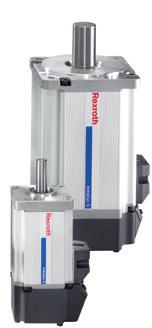
74 7 OBB omega modules R (206-05) Attachments and accessories IndraDyn S servo motors MSK B G E D A H H 2 H C C L m R A F Schematic motor illustration Motor Dimensions (mm) A B C C ØD ØE ØF ØG H H H 2 L m R k6 j6 without holding brake with holding brake MSK 00C R8 MSK 050C R8 MSK 076C R2 Motor data Motor n max M 0 M max M br J m J br m m m br (min - ) (Nm) (Nm) (Nm) (kgm 2 ) (kgm 2 ) (kg) (kg) MSK 00C MSK 050C MSK 076C Motor data independent of the Omega module J br = mass moment of inertia of holding brake J m = mass moment of inertia of the motor L m = length of the motor M 0 = torque at standstill M br = holding torque of holding brake when switched off M max = maximum possible motor torque m m = mass of motor m br = mass of the holding brake n max = maximum speed
75 R (206-05) OBB omega modules 75 Option number ) Motor Material number Version Type designation Holding brake Without With 86 MSK00C-0600 R X MSK00C-0600-NN-M-UG0-NNNN 87 R90606 X MSK00C-0600-NN-M-UG-NNNN 88 MSK050C-0600 R92985 X MSK050C-0600-NN-M-UG0-NNNN 89 R X MSK050C-0600-NN-M-UG-NNNN 92 MSK076C-050 R98098 X MSK076C-050-NN-M-UG0-NNNN 9 R957 X MSK076C-050-NN-M-UG-NNNN ) From Configuration and ordering table Version Plain shaft with shaft seal Multi-turn absolute encoder M (Hiperface) Cooling system: natural convection Protection class IP65 (housing) With or without holding brake Notes The motors can be supplied complete with controllers and control units. For further motor types and more information on motors, controllers and control units, please refer to the following Rexroth catalogs on drive technology: Drive System Rexroth IndraDrive, R Automation systems and control components, R Rexroth IndraDyn S Synchronous Motors MSK, R Recommended motor/controller combination Motor MSK 00C-0600 MSK 00C-0600 MSK 050C-0600 MSK 076C-050 Controller HCS 0.E-W0008 HCS 0.E-W008 HCS 0.E-W0028 HCS 0.E-W005 Torque/speed characteristic (schematic) M (Nm) M max M 0 n (min ) n max

76 76 OBB omega modules R (206-05) Attachments and accessories IndraDyn S servo motors MSM G A E D F H L m B C C Schematic motor illustration Motor Dimensions (mm) A B C C ØD ØE ØF ØG H L m k6 j6 Without holding brake With holding brake MSM 0C MSM 0B Motor data Motor n max M 0 M max M br J m J br m m m br (min - ) (Nm) (Nm) (Nm) (kgm 2 ) (kgm 2 ) (kg) (kg) MSM 0C MSM 0B J br J m L m = mass moment of inertia of holding brake = mass moment of inertia of the motor = length of the motor M 0 = torque at standstill M br = holding torque of the holding brake (normally closed) M max = maximum possible motor torque m m = mass of motor m br = mass of holding brake n max = maximum speed
77 R (206-05) OBB omega modules 77 Option number ) Motor Material number Version Type designation Holding brake Without With 8 MSM 0C-000 R925 X MSM 0C-000-NN-M5-MH0 9 R926 X MSM 0C-000-NN-M5-MH 0 MSM 0B-000 R927 X MSM 0B-000-NN-M5-MH0 R928 X MSM 0B-000-NN-M5-MH ) From Configuration and ordering table Version: Plain shaft without shaft seal Mutiturn absolute encoder M5 (20 bit, absolute encoder function only available with buffer battery) Cooling system: natural convection Protection class IP5 (shaft IP0) With or without holding brake Metal round connector M7 Notes The motors can be supplied complete with controllers and control units. For further motor types and more information on motors, controllers and control units, please refer to the following Rexroth catalogs: Drive System Rexroth IndraDrive, R Automation systems and control components, R Rexroth IndraDyn S Synchronous Motors MSM R9297 Recommended motor/controller combination Motor Controller MSM 0C-000 HCS 0.E-W0009 MSM 0B-000 HCS 0.E-W00 Torque/speed characteristic (schematic) M (Nm) M max M 0 n (min ) n max

78 78 OBB omega modules R (206-05) EasyHandling The perfect system solution for every application Efficient production processes are the key to your success in the marketplace. Today s environment, defined by rapid change and short product cycles, demands flexible systems with an optimal design and configuration. EasyHandling gives you the tools you need to automate your handling applications with greater ease, speed, and efficiency. EasyHandling is more than just a modular collection of mechanical components; it takes an evolutionary step forward by providing an all-inclusive system solution our best solution for your requirements.

79 R (206-05) OBB omega modules 79 EasyHandling Easier. Faster. More Economical. Easier to get results that fit Tailor-made solutions just like that with support throughout. Faster route to your ideal application Effortless adaptation, even to future requirements fast and flexible scalability. More economical through unparalleled efficiency Optimizes processes from project planning through to operations with significant savings on resources. Engineering up to 70% faster EasyHandling tools help users right from the component selection stage, proposing solutions with all the necessary information on parts lists, technical data and CAD drawings. Installation saves up to 60% on time Thanks to positive-locking interfaces, the mechanical components are perfectly aligned and accurately connected right away. Start-up reduces your effort by up to 90% With the smart start-up assistant EasyWizard, parameterization and configuration become child's play. Your handling system will be ready to go in just a few clicks. Production more economical and more efficient Rexroth enhances the system effectiveness still further with smart application tools: The drive controller software outputs maintenance-related messages to the user based on operating hours and travel to help schedule servicing at the right intervals. The result: longer life and reduced risk of failure. Future developments continuous improvement Prepare for future market developments now: One of the great features of EasyHandling systems is their systematic openness. The flexibility of the mechanical and electrical components allows you to adapt quickly and efficiently to new production requirements.


80 80 OBB omega modules R (206-05) EasyHandling EasyHandling more than just a kit of components The modular system concept that ideally builds on itself


81 R (206-05) OBB omega modules 8 basic Made-to-measure mechanics EasyHandling basic contains all the mechatronic components you need to build complete, single- or multi-axis systems to match your individual needs. All of the component interfaces are systematically standardized, making it possible to combine them at will. Practical tools and aids make selection and configuration even easier. comfort Getting started even faster EasyHandling comfort expands the Basic component range by adding powerful servo drives with multiple protocol capability. The universal, smart control units are ideally suited for a variety of handling tasks. Unique: with the EasyWizard start-up assistant, linear systems are ready to use after entering just a few product-specific parameters. advanced Controls for demanding requirements With the freely scalable, high-performing motion logic control system, EasyHandling advanced makes configuration and handling even easier. Predefined functions covering more than 90 percent of all handling applications eliminate the need for lengthy programming. For more information about EasyHandling, see the brochure EasyHandling more than just a kit of components R
82 82 OBB omega modules R (206-05) Service and information Operating conditions Normal operating conditions Ambient temperature No passing below the dew point 0 C... 0 C ϑ Load 0.2 C Travel distance s min ) OBB mm OBB mm OBB-20 5 mm Contamination Not permitted ) Minimum travel distance to ensure a reliable lubrication distribution. Design notes ccmoved parts: Safety devices and guards necessary c c For vertical installations: Arresting devices necessary to protect against falling loads Required and supplementary documentation For further instructions and information, please refer to documentation belonging to this product. Safety Instructions for Linear Motion Systems You can find PDF files of these documents in the Internet at We would also be pleased to send you the documents. If you are unsure about using this product, please contact Bosch Rexroth.
83 R (206-05) OBB omega modules 8 Lubrication Lubrication notes Omega modules receive basic lubrication with Dynalub 50 and are only designed for grease lubrication using a manual grease gun. The only maintenance required is relubrication of the integrated Ball Rail System via one of the two funnel-type lube nipples (). Lubrication point Funnel-type lube nipple DIN 05 Type D Lubricants For lubricant quantities and intervals, see Instructions for Omega Modules. Size Grease Material number OBB-055 OBB-085 Dynalub 50 (Bosch Rexroth) R (Cartridge 00 g) OBB-20 NLGI grade 2 lithium-based high-performance grease as per DIN 588 (KP2K-20 as per DIN 5825) Alternative greases Elkalub GLS 5 / N2 (Chemie-Technik) Castrol Longtime PD2 (Castrol) c c Do not use greases containing solid particles (e.g. graphite or MoS 2 )! ccfor lubrication in short-stroke applications (travel path < s min ), please consult us. Documentation Standard report Option 0 The standard report serves to confirm that the checks listed in the report have been carried out and that the measured values lie within the permissible tolerances. Controls listed in the standard report: functional checks of mechanical components functional checks of electrical components design is in accordance with order confirmation

 8 u = lead constant (mm/rev) 9 v max = max. speed (m/s) 0 a max = max.")
84 8 OBB omega modules R (206-05) Service and information Parameterization (commissioning) Besides reference information for the production of the linear motion system, there are also technical parameters specified for commissioning on the nameplate. 2 MNR: R25678 TYP: OBB-085-NN- CS: D-979 Schweinfurt Made in Germany FD: s max (mm) u (mm/u) v max (m/s) a max (m/s 2 ) M max (Nm) d i ccw Material number 2 Type designation Size Customer information 5 Date of manufacture 6 Manufacturing location 7 s max = max. travel range (mm) 8 u = lead constant (mm/rev) 9 v max = max. speed (m/s) 0 a max = max. acceleration (m/s 2 ) M max = max. drive torque at motor journal (Nm) 2 d = rotational direction of the motor to move in positive direction CW CCW Clockwise Counter clockwise i = gear ratio X For Omega modules, the nameplate is mounted on the carriage on the drive side. (See fig.) MNR: R25678 TYP: OBB-085-NN- CS: D-979 Schweinfurt Made in Germany 720 FD: 8 s max (mm) u (mm/u) v max (m/s) a max (m/s 2 ) M max (Nm) d i ccw 8


85 R (206-05) OBB omega modules 85 Further information Bosch Rexroth homepage: Omega module product information: linear-motion-technology/linear-motion-systems/omega-module/index
Product description. Compact Modules. Characteristic features. Further highlights
 4 Compact Modules Product description Characteristic features Five fine-tuned sizes based on a compact precision aluminum profile with two integrated pre-tensioned ball rail systems Identical external
Product Description. Further highlights. Outstanding features. 4 Bosch Rexroth Corporation Miniature Linear Modules R310A 2418 (2009.
 4 Bosch Rexroth orporation Miniature Linear Modules R310A 2418 (2009.05) Product Description Outstanding features Rexroth Miniature Linear Modules are precise, ready-to-install linear motion systems that
R310EN 2403 ( ) The Drive & Control Company
 The Drive & Control Company") Feed Modules VKK R310EN 2403 (2008.09) The Drive & Control Company Linear Motion and Assembly Technologies Ball Rail Systems Roller Rail Systems Linear Bushings and Shafts Ball Screw Drives Linear Motion
Feed Modules VKK R310EN 2403 (2008.09) The Drive & Control Company Linear Motion and Assembly Technologies Ball Rail Systems Roller Rail Systems Linear Bushings and Shafts Ball Screw Drives Linear Motion
Drive Units with Ball Screw Drives R310EN 3304 ( ) The Drive & Control Company
 The Drive & Control Company") Drive Units with Ball Screw Drives R310EN 3304 (2007.05) The Drive & Control Company Linear Motion and Assembly Technologies Ball Rail Systems Roller Rail Systems Linear Bushings and Shafts Precision Ball
Drive Units with Ball Screw Drives R310EN 3304 (2007.05) The Drive & Control Company Linear Motion and Assembly Technologies Ball Rail Systems Roller Rail Systems Linear Bushings and Shafts Precision Ball
Linear guide drives. Synchronous shafts The use of synchronous shafts enables several linear axes to be operated with one drive.
 Linear guide drives Drive concept The linear guides are driven via the hollow shaft in the drive head. The drive head is used to directly install a motor or alternatively (in connection with a center shaft)
Cam Roller Guides. The Drive and Control Company. Service Automation. Electric Drives and Controls. Linear Motion and Assembly Technologies
 Industrial Hydraulics Electric Drives and Controls Linear Motion and Assembly Technologies Pneumatics Service Automation Mobile Hydraulics Cam Roller Guides The Drive and Control Company Linear Motion
CTV series CHARACTERISTICS LINEAR UNITS
 CTV series CHARACTERISTICS The CTV series describes s with a precision ball screw drive and two parallel, integrated, Zerobacklash rail guides. Compact dimensions allow high performance features such as,
Rotary modules.
 Rotary modules www.comoso.com www.comoso.com Rotary modules ROTARY MODULES Series Size Page Rotary modules RM swivel unit 156 RM 08 160 RM 10 162 RM 12 164 RM 15 168 RM 21 172 RM rotor 176 RM 50 180 RM
R-Plus System Frontespizio_R_PlusSystem.indd 1 11/06/ :32:02
 R-Plus System R-Plus System R-Plus system R-Plus system description Fig. R-Plus system R-Plus System is Rollon s series of rack & pinion driven actuators. Rollon R-Plus System series linear units are designed
LINE TECH Linear Modules. Ready to built-in linear modules with drive
 Ready to built-in linear modules with drive Anodized profile, produced in extrusion molding method Linear rail guiding system (LM3 LM5) Actuation by ball screw, high-helix lead _ screw or toothed belt
Precision Ball Screw/Spline
 58-2E Models BNS-A, BNS, NS-A and NS Seal Outer ring Shim plate Seal Spline nut Seal Collar Shim plate Seal End cap Ball Outer ring Ball screw nut Outer ring Ball Retainer Retainer Outer ring Point of
Linear Motion Slides. The Drive and Control Company. Service Automation. Electric Drives and Controls. Linear Motion and Assembly Technologies
 Industrial Hydraulics Electric Drives and Controls inear Motion and ssembly Technologies Pneumatics Service utomation Mobile Hydraulics inear Motion Slides The Drive and Control Company The Product Range
Selection Calculations For Linear & Rotary Actuators
 H-8 For Electric Linear Slides and Electric Cylinders First determine your series, then select your product. Select the actuator that you will use based on the following flow charts: Selection Procedure
ZF Maschinenantriebe GmbH Industrial Drives. Planetary gearboxes Economy Series for Servomotors
 ZF Maschinenantriebe GmbH Industrial rives Planetary gearboxes Economy Series for Servomotors 2 ZF-uoplan 2K Two-speed Gearboxes ZF-Ecolift Elevator Gearboxes ZF-Servoplan G ompact Gearbox ZF-Tiratron
Variable Displacement Plug-In Motor A6VE. Series 6, for open and closed circuits Axial tapered piston, bent axis design
 rueninghaus Hydromatik Series 6, for open and closed circuits xial tapered piston, bent axis design Size 28...20 Nom. pressure up to 400 bar Peak pressure up to 40 bar RE 9606/0.97 RE 9606/0.97 replaces
Actuators with ball monorail guidance system and ball screw drive MKUVE15-KGT, MKUVE20-KGT
 Actuators with ball monorail guidance system and ball screw drive MKUVE15-KGT, MKUVE20-KGT Product overview Actuators with ball monorail guidance system and ball screw drive Actuators with ball monorail
ElectroMechanical Cylinder LEMC
 www.lmotion.ru lmotionmail@ya.ru.: (9)9160 ElectroMechanical Cylinder LEMC THE POWER OF KNOWLEDGE ENGINEERING www.lmotion.ru lmotionmail@ya.ru.: (9)9160 ElectroMechanical Cylinder LEMC enefits High efficiency
ElectroMechanical Cylinder LEMC
 ElectroMechanical Cylinder EMC ElectroMechanical Cylinder EMC enefits High eficiency ong service life from use of SKF planetary roller screw Compact and robust structural design Modular concept with multiple
Lexium integrated drives
 Presentation GBX planetary gearbox Presentation In many cases the axis controller requires the use of a planetary gearbox for adjustment of speed of rotation and torque; the accuracy required by the application
T20WN. Data Sheet. Torque transducers. Special features. Installation example with bellows couplings. B en
 T20WN Torque transducers Data Sheet Special features - Nominal (rated) torques 0.1 N m, 0.2 N m, 0. N m, 1 N m, 2 N m, N m, 10 N m, 20 N m, 0 N m, 100 N m, 200 N m - Accuracy class: 0.2 - Contactless transmission
UNI EN ISO 9001:2008 UNI EN ISO 14001:2004 BS OHSAS 18001:2007 EC DIRECTIVE 2014/34/EU (ATEX) CERTIFIED MANAGEMENT SYSTEM
 CERTIFIED MANAGEMENT SYSTEM") EN ISM-BSM CERTIFIED Technology Made in Italy Since 1955 the Varvel Group has been making speed reducers and variators for light industry applications. Reliable partner in power transmission equipment
EN ISM-BSM CERTIFIED Technology Made in Italy Since 1955 the Varvel Group has been making speed reducers and variators for light industry applications. Reliable partner in power transmission equipment
the foundation of any business starts here
 the foundation of any business starts here TABLE OF CONTENT The Company... 3 Electric Motors... 4 Gearboxes... 5 Automation Products... 6 Electric Components... 9 Pneumatics... 12 Hydraulics... 13 Handling
Selection Calculations For Motorized Actuators
 Selection Calculations/ Selection Calculations For Linear Slides and Cylinders Select from the EZS Series, EZS Series for Cleanroom Use, EZC Series First determine your series, then select your model.
Compendium Screw Jacks
 Compendium Screw Jacks Screw Jack Technology Overview of chapters Useful information Project planning Screw jacks Bevel gear boxes Lifting screw protective covers Couplings and connecting shafts Accessories
NR ROTARY RING TABLE: FLEXIBLE IN EVERY RESPECT
 NR FREELY PROGRAMMABLE ROTARY TABLES NR ROTARY RING TABLE All NR rings allow customer-specific drive motors to be connected NR ROTARY RING TABLE: FLEXIBLE IN EVERY RESPECT WHEN IT S GOT TO BE EXACT We
Points. Precision Positioning Table TU. Variation. Major product specifications With flange
 9 0 Precision Positioning Table Ball screw inear Points lide table with high accuracy and high rigidity in a single structure lide table Compact and slim type positioning table with an original U-shaped
Digital AC Motors MHD
 Digital AC Motors MHD090 8-1 8 MHD090 8.1 Technical Data Description Symbol Unit MHD090B-035 Type of cooling Natural Natural Surface Liquid Motor overtemperature 60 K 100 K 60 K/100 K 60 K/100 K Electric
Vane Type Rotary Actuators Series Variations
 Vane Type Rotary Actuators Series Variations Vane Type Exterior CRB Series 0,, 0,, CRBU Series 0,, 0,, CRB Series, 6, 80, Has a compact body with exterior dimensions that do not change regardless of the
The basic dynamic load rating C is a statistical number and it is based on 90% of the bearings surviving 50 km of travel carrying the full load.
 Technical data Load Rating & Life Under normal conditions, the linear rail system can be damaged by metal fatigue as the result of repeated stress. The repeated stress causes flaking of the raceways and
ER2 Short-head Electric Chain Hoist
 O/M NO.SHER2-0903-CE-00 ER2 Short-head Electric Chain Hoist (250kg to 5t) Operation Manual (SHER2M/SHER2SG/SHER2SP) Introduction The KITO Short-head Electric Chain Hoist is intended for effective use in
APEX DYNAMICS, INC. Staianless
 APEX DYNAMICS, INC. HIGH PRECISION PLANETARY GEARBOXES AE / AER Series Staianless High precision high speed planetary gearboxes AE / AER series Apex Dynamics, Inc. is the world s most productive manufacturer
HPG xxx 030 C1 C2 C3. High performance angle gearboxes. Output. Input. Drawings. C with option motor flange. View x. Centering View y.
 HPG 030 1 2 3 Input Output 1 View M6 ( deep) 0 Ø4 H (2.2 deep) 18.0 M6 ( deep) 0 2 3 M6 ( deep) 2 13.0 4 2.0 18.0 24.0 M Ø12 k6 6 M6 ( deep) M6 ( deep) 3 Eample HPG 030 2 with option motor flange 0 M6
Ball screw. Linear. Coupling cover. 1Positioning table of a structure with enhanced sealing property. 3 High corrosion resistance
 Cleanroom Precision Positioning Table TC Ball screw TC EB Slide table inear Way Side cover Stainless sheet Motor bracket inear Coupling cover Pipe threads for suction connector Points ight weight, low
Vacuum capacitors overview Capacitor selection guides
 JENNINGS TECHNOLOGY Vacuum capacitors overview Capacitor selection guides Capacitors by type Capacitor type Vacuum variable Capacity max. (pf) Test voltage / Hz Model no. series Page number 7.,, 1 CVDD-
Identification Number
 Identification Number The specification of Micro Linear Way LWL is specified by the identification number, which consists of a model code, a size, a part code, a preload symbol, a classification symbol,
Backlash-free Torque Limiting Clutches
 ES -Compact Backlash-free Torque Limiting Clutches www..de Instant separation on overload Permanent backlash-free torque transmission Readable torque adjustment Synchronous, ratchetting and overload designs
SIZING AND SELECTION. According to DIN 740 part 2 SIZING
 SIZING SIZING AND SELECTION According to DIN 740 part 2 RW-AMERICA.COM 7 SIZING AND SELECTION SAFETY COUPLINGS ST SYMBOLS T AR = Disengagement torque of the coupling (Nm) K = Service factor T max = Maximum
ROTARY MOTION CONTROL
 ROTARY MOTION CONTROL Technical Data Sheet Nexen Mechanical Torque Limiter Family PMT / PMK / PMC 2TC 2CC ECC PCC Mechanical Torque Limiter The trend in industry is to design and incorporate more automation
Example of Calculating the Nominal Life
 Condition (Horizontal Installation) Assumed model number : KR 5520A LM Guide unit (C = 800N, C 0 = 6900N) Ball Screw unit (C a = 620N, C 0a = 9290N) Bearing unit(fixed Side) (C a = 7600N, P 0a = 990N)
Members Subjected to Torsional Loads
 Members Subjected to Torsional Loads Torsion of circular shafts Definition of Torsion: Consider a shaft rigidly clamped at one end and twisted at the other end by a torque T = F.d applied in a plane perpendicular
APEX DYNAMICS, INC. Staianless
 APE DYNAMICS, INC. HIGH PRECISION HIGH SPEED PLANETARY GEARBOES AF / AFR Series Staianless High precision high speed planetary gearboxes AF / AFR series Apex Dynamics, Inc. is the world s most productive
 Selection of jack size No. 5 Check again with ball screw jack Type J-B. Yes. Set the hand wheel radius if the screw jack is to be used for manual operation. Yes. Yes. Specification Select temporarily the
SKF actuators available for quick delivery. Selection guide
 SKF actuators available for quick delivery Selection guide A wide range of SKF actuators available for quick delivery Industrial actuator 24 Volt DC Load range 1 000 to 4 000 N Speed range 5 to 52 mm/s
Moment of inertia and angular acceleration with Cobra 3
 Principle A known torque is applied to a body that can rotate about a fixed axis with minimal friction. Angle and angular velocity are measured over the time and the moment of inertia is determined. The
DRS 61: Incremental encoders, number of lines and zero pulse width freely programmable DRS 60: Incremental Encoders with Zero-Pulse-Teach
 NEW DRS : Incremental encoders, number of lines and zero pulse width freely programmable DRS : s with Zero-Pulse-Teach Further highlights of this generation of encoders: Simple zero-pulse-teach by pressing
The perfect Torque Limiting Clutch for
 The perfect Torque Limiting Clutch for Machine Tools Packaging Machinery Printing and Paper Machinery Automated Systems Power Transmission compact, backlash-free torque limiting clutch Immediate disengagement
BSD MODULFLEX R Torsionally Rigid Couplings
 BSD MODULFLEX R Torsionally Rigid Couplings for T1F Torque Flange View B Thread opening turned in sectionel plane b b 6 b 7 b 2 b 8 b 3 b za View A A B NVm 1 NVm View A btot Reference dimension X X 2 NVm
Check-Q-meter. Table of contents. Features. Functions. RE 27551/ /10 Replaces: Type FD
 Check-Q-meter RE /0.0 /0 Replaces: 09.9 Type FD Nominal size... Series ax. Operating pressure 0 bar ax. Flow 0 l/min K9/ Table of contents Contents Page Features Functions Ordering details Symbols Functional
TSCHAN S US Elastische Kupplungen Flexible Couplings TNS Flexible Couplings. Partner for Performance
 US 11 2015 TSCHAN S Elastische Kupplungen Flexible Couplings TNS Flexible Couplings Partner for Performance www.ringfeder.com Welcome to your system supplier for every aspect of power transmission Today
API 11E - Specification for Pumping Units
 API 11E - Specification for Pumping Units 5 Beam Pump Structure Requirements 5.1 General Requirements for beam pump structures are specified in the following sections. Only loads imposed on the structure
Dynamic Tests on Ring Shear Apparatus
 , July 1-3, 2015, London, U.K. Dynamic Tests on Ring Shear Apparatus G. Di Massa Member IAENG, S. Pagano, M. Ramondini Abstract Ring shear apparatus are used to determine the ultimate shear strength of
Experiment Instructions. Deformation of Frames
 Experiment Instructions SE 0.20 Deformation of Frames Experiment Instructions This manual must be kept by the unit. Before operating the unit: - Read this manual. - All participants must be instructed
Technical Reference Selection calculations Motors Motorized Actuators Cooling Fans Technical Service Life Reference Standard AC Motors
 calculations... H-2 H-2 H Technical Reference H-8 H-28... H-29 AC... H-33... H-0 AC... H-6... H-55... H-58... H-66... H-68... H-77 H- / For Selecting a motor that satisfies the specifications required
3D Drawing - CARIF 260 BSA
 D Drawing - CARIF 0 BSA DRAWING CODE DRAWING NAME NUMBER ASS000 Basement ASS00 Vice Base ASS00 Vice A ASS00B Vice B ASS00 Frame A ASS00B Frame B ASS000 Frame Cylinder A ASS000B Frame Cylinder B ASS000
Planetary Screw Assemblies PLSA
 Planetary Screw Assemblies PLSA Ernst-Sachs-Straße 100 97424 Schweinfurt Tel. +49 9721 937-0 Fax +49 9721 937-275 www.boschrexroth.com Catalog "Planetary Screw Assemblies PLSA" R310XX 3308 (2014.01) Dear
Series MHY2/MHW Angular Gripper. Cam actuation style is now standardized! MHZ2 MHZJ2 MHQ MHL2 MHR MHK MHS MHC2 MHT2 MHY2 MHW2 MRHQ 2.
 18 Angular Gripper Cam Style Rack & Pinion Style Series / Cam actuation style is now standardized! 2.8-1 18 Angular Gripper 18 Angular Gripper Series / Cam Style Rack & Pinion Style Series / Series MHY/Cam
Calculating the Applied Load
 The LM Guide is capable of receiving loads and moments in all directions that are generated due to the mounting orientation, alignment, gravity center position of a traveling object, thrust position and
Rodless cylinders Series 1600
 Rodless cylinders Series 00 Basic version 0.Ø.stroke.0.M Max. stroke mt.) AL AI RA RB AF TC AM L LA+stroke AH TD AE TA RV Possibility of a single feed cylinder head AI AP AB AC AD TD TE TB AG RT Left head
Rail Guide Modular Linear Actuators DSM
 Roller Guide Modular Linear Actuators DLM, DLVM Rail Guide Modular Linear Actuators DSM nookindustries.com toll-free (800) 32-7800 25 DLM 20, 60, 200 Linear Motor Drive Specifications Function: This unit
Planetary Screw Assemblies PLSA
 Planetary Screw Assemblies PLSA R310EN 3308 (2011-09) The Drive & Control Company C/ Centauro, 13 Área Empresarial Las Cubiertas 28971-Griñón (Madrid) T. 0034 91 126 6627 info@diversiatec.com www.diversiatec.com
DRIFTER PLOW-IN-A-BOX ASSEMBLY / OWNER S MANUAL
 DRIFTER PLOW-IN-A-BOX ASSEMBLY / OWNER S MANUAL Part No: 10-0550 OPERATING INSTRUCTIONS Congratulations! You ve just purchased one of the industry s top plow systems. The DRIFTER Plow System works great
Hilti North America Installation Technical Manual Technical Data MI System Version
 MIC-SA-MAH 174671 Hilti North America Installation Technical Manual Technical Data MI System Version 1. 08.017 Terms of common cooperation / Legal disclaimer The product technical data published in these
External gear pump Type G3, Series 3X
 NS to 5 External gear pump Type G3, Series 3X Up to 2 bar Up to 5.2 cm 3 RE 039/07.00 Replaces: 03.00 Plain bearings for high loads Mono-block bearing New principle of hydrostatic gap compensation Drive
EXPERIMENTAL RESEARCH REGARDING TRANSIENT REGIME OF KINEMATIC CHAINS INCLUDING PLANETARY TRANSMISSIONS USED IN INDUSTRIAL ROBOTS
 International Journal of Modern Manufacturing Technologies ISSN 2067 3604, Vol. VIII, No. 1 / 2016 EXPERIMENTAL RESEARCH REGARDING TRANSIENT REGIME OF KINEMATIC CHAINS INCLUDING PLANETARY TRANSMISSIONS
CONTENTS INDEX P. 2 P. 3-4 PRODUCT FEATURES P. 5-6 PRODUCT STRUCTURE P. 7-8 PRODUCT APPLICATIONS PRODUCT SELECTION P P. 11 MODEL LIST P.
 EMER-FLEX COUPLING CONTENTS INDEX PRODUCT FEATURES PRODUCT STRUCTURE PRODUCT APPLICATIONS PRODUCT SELECTION MODEL LIST NEF-HUB NES Series P. 2 P. 3-4 P. 5-6 P. 7-8 P. 9- P. P. 2 P. 3-4 NEF Series Spacer
Monoca rrier TM CBLOCK C1-C22 C23-C68 C69-C88
 C-1 TM 1. Features C1 2. Classifications and Series C. Optional Components C. Selection of.1. Procedures for Selecting C.2. Rigidity C.. Maximum Speed C.. Accuracy Grade C.. Stroke and Ball Screw Lead
HRN/HRN-C Series Hydraulic Vane Rotary Actuators
 HRN/ Hydraulic Vane Rotary Actuators Vane Actuators Tork-Mor HRN Contents Features... 2 Ordering Information... Engineering Data / Specifications... Dimensions... Features... 1 Ordering Information...12
STANDARD & OPTION 1 X, Y, Z axis linear scale 2 Saddle slideway cover 3 Table slideway cover 4 Table Splash guard 5 Working light 6 Coolant circulatio
 STANDARD & OPTION X, Y, Z axis linear scale 2 Saddle slideway cover 3 Table slideway cover Table Splash guard 5 Working light 6 Coolant circulation system 7 8 ITEM Bolts & leveling pads for installation
ø6, ø10, ø15, ø20, ø25, ø32, ø40, ø50, ø63 How to Order Switch rail Nil Standard stroke Refer to page 12 for standard stroke.
 Magnetically Coupled Rodless Cylinder: Direct Mount ype Series ø, ø, ø, ø, ø, ø, ø, ø0, ø Direct mount type mm mm mm mm mm mm mm 0 0 mm mm 00 MB Piping type Both sides piping type Centralized piping type
C-Lube Linear Way ML ML MLF
 Maintenance ree & U.S. PTTD C-Lube Linear ay Variation of C-Lube Linear ay Shape Length of slide unit Model code C-Lube Linear ay is a linear motion rolling guide, incorporating the C-Lube as a components
CHAPTER 17 FLEXIBLE MECHANICAL ELEMENTS LECTURE NOTES DR. HAFTIRMAN
 CHAPTER 17 LEXIBLE MECHANICAL ELEMENTS LECTURE NOTES DR. HATIRMAN lexible Mechanical Elements Belts Roller chains Wire rope lexible shafts lexible Mechanical Elements Belts, ropes, chains, and other similar
1 High precision, high rigidity positioning table
 TSHM CTHM 11 116 Precision Positioning Table H Ball screw TSH M Ball screw Slide table inear Way Bed inear Points 1 High precision, high rigidity positioning table High precision, high rigidity positioning
PLOW MOUNT KIT FOR POLARIS RANGER P/N ASSEMBLY / OWNERS MANUAL
 PLOW MOUNT KIT FOR POLARIS RANGER P/N 34-3010 ASSEMBLY / OWNERS MANUAL Application PLOW PUSH FRAME NO. 34-0000 or 34-0070 Before you begin, please read these instructions and check to be sure all parts
THE NEW 1.1 MN m TORQUE STANDARD MACHINE OF THE PTB BRAUNSCHWEIG/GERMANY
 THE NEW 1.1 MN m TORQUE STANDARD MACHINE OF THE PTB BRAUNSCHWEIG/GERMANY D. Peschel 1, D. Mauersberger 1, D. Schwind 2, U. Kolwinski 2 1 Solid mechanics department, PTB, Germany 2 Gassmann Theiss Messtechnik
VOLUMEC. Valve Position Indicator 5
 VOLUMEC Valve Position Indicator 5 2 KRACHT CORP. 8600 S Wilkinson Way Unit A Perrysburg, OH 43551 USA P +1 419 874 1000 F +1 419 874 1006 flowmeters@krachtcorp.com www.krachtcorp.com VOLUMEC Valve Position
second PLSA line R310EN 3308 ( )
") 01_1 Planetary st Headline_36 Screw Assemblies pt/14.4 mm second PLSA line R310EN 3308 (2011-09) 2 Planetary Screw Assemblies PLSA Planetary Screw Assemblies PLSA Product Overview 3 Nuts, Screws, Screw
01_1 Planetary st Headline_36 Screw Assemblies pt/14.4 mm second PLSA line R310EN 3308 (2011-09) 2 Planetary Screw Assemblies PLSA Planetary Screw Assemblies PLSA Product Overview 3 Nuts, Screws, Screw
AE / AER Series. AER Series
 AE / AER Series Characteristic Highlights True helical gear design Precision helical gearing increases tooth to tooth contact ratio by over % vs spur gearing. The helix angle produces smooth and quiet
Clausing Industrial, Inc. Variable Speed 20" Single and Multi-spindle, Belt Drive Industrial Drill Presses
 www.clausing-industrial.com Variable Speed 20" Single and Multi-spindle, Belt Drive Industrial Drill Presses Clausing Industrial, Inc. Two Speed Variable Speeds 150-2000rpm Variable Speeds 200-1300rpm
Servomotors Order Catalog. LSP-Servomotors with optional planetary gearbox Stall torque 0.18 to 110 Nm
 Servomotors Order Catalog LSP-Servomotors with optional planetary gearbox Stall torque 0.8 to 0 Nm Order Catalogue LSP Servomotors ID no.: 08.8B.-0 Date: 0/07 Subject to technical change without notice.
BASE. Rotary limit switch. OptiOnS. FEAtuRES. CERtiFiCAtiOnS
 Rotary limit switch BASE Rotary limit switch used to control and measure the movement of industrial machines. Its compact size make it suitable for use in narrow spaces. FEAtuRES It consists of a gear
AF SERIES AWEA MECHANTRONIC CO., LTD. High Performance Vertical Machining Center AGENT ISO 9001 ISO 14001
 AWEA MECHANTRONIC CO., LTD. HEADQUARTERS 629, Suezhetou Section, Kwanpu Rd., Wenshan Li, Hsinpu, Hsinchu, Taiwan TEL : +886-3-88-191 FAX : +886-3-88-19 Website : www.awea.com CENTRAL TAIWAN SCIENCE PARK
U.S. Patents 6,290,217 6,244,579
 CR CR Series Overview U.S. Patents 6,90,7 6,,579 For the best in vibration isolation capabilities, choose Enidine s. Smaller than traditional wire ropes, these unique isolators provide cost-effective,
Lightweight. Geislinger Gesilco
 Lightweight Geislinger Gesilco The Geislinger Gesilco product range is based on more than 20 years of experience in developing fibre composite couplings and shafts. The maintenance-free composite membranes
MonocarrierTM Monocarrier
 Monocarrier TM Significantly saves designing load of machinery through an integration of linear motion components in one unit. Demonstrates high performance in a wide range of applications, including assembling
Load Washers. Force. for Forces of 7, kn. F z. Type 9001A A 9081B, 9091B
 Force Load Washers for Forces of 7,5... 1 200 kn Type 9001A... 9071A 9081B, 9091B 1-component force sensor for measuring dynamic and quasistatic forces in z direction. F z Calibrated measuring range 100
AC Synchronous Motors
 AC Synchronous Motors A C S Y N C H R O N O U S M O T O R S AC Synchronous Motors Kollmorgen AC synchronous motors are high pole count motors that naturally turn at slower speeds (72 or 60 rpm). at 72
SNL plummer block housings, 2, 3, 5 and 6 series Other bearing housings Large SNL plummer block housings
 Bearing housings SNL plummer block housings, 2, 3, 5 and 6 series... 1033 Other bearing housings... 1058 Large SNL plummer block housings... 1058 SONL plummer block housings... 1059 SDG plummer block housings...
ENSC387: Introduction to Electromechanical Sensors and Actuators LAB 3: USING STRAIN GAUGES TO FIND POISSON S RATIO AND YOUNG S MODULUS
 ENSC387: Introduction to Electromechanical Sensors and Actuators LAB 3: USING STRAIN GAUGES TO FIND POISSON S RATIO AND YOUNG S MODULUS 1 Introduction... 3 2 Objective... 3 3 Supplies... 3 4 Theory...
Sensor Accessories. Rotary Motion Accessory Pack. Pendulum Rod with two masses, Angular Momentum disc set and Linear Rack with mini c-clamp
 Sensor Accessories Rotary Motion Accessory Pack (Product No 3288) Pendulum Rod with two masses, Angular Momentum disc set and Linear Rack with mini c-clamp DATA HARVEST Data Harvest Group Ltd 1 Eden Court,
Facts and figures MULTILIFT SELECT 15
 Facts and figures MULTILIFT SELECT 15 www.arburg.com MULTILIFT SELECT 15 Technical data min. 180 Stroke Z-axis Stroke X-axis Clamping face fixed mould platen 220 E A D K Stroke Y axis 195 B 2) C 157 P
System Components. Electric Motors.
 System Components Electric Motors www.powerjacks.com Contents.1. Electric Motors.1.1. AC Motors.1.. AC Motor Performance 0 rpm ( pole).1.. AC Motor Performance 00 rpm ( pole).1.. AC Motors with Integral
APPENDIX. SELECTING THE SureServo SERVO SYSTEM. In This Appendix... Selecting the SureServo Servo System...B 2. Leadscrew - Example Calculations...
 SELECTING THE SureServo SERVO SYSTEM APPENDIX B In This Appendix... Selecting the SureServo Servo System............B 2 The Selection Procedure......................................B 2 How many pulses
Stress Analysis Lecture 3 ME 276 Spring Dr./ Ahmed Mohamed Nagib Elmekawy
 Stress Analysis Lecture 3 ME 276 Spring 2017-2018 Dr./ Ahmed Mohamed Nagib Elmekawy Axial Stress 2 Beam under the action of two tensile forces 3 Beam under the action of two tensile forces 4 Shear Stress
Variable Speed 20" Single and Multi-spindle, Belt Drive Industrial Drill Presses
 www.clausing-industrial.com Variable Speed 20" Single and Multi-spindle, Belt Drive Industrial Drill Presses Two Speed Variable Speeds 150-2000rpm Variable Speeds 200-1300rpm Variable Speeds 300-2000rpm
Servo Motor Selection Flow Chart
 Servo otor Selection Flow Chart START Selection Has the machine Been Selected? YES NO Explanation etermine the size, mass, coefficient of References friction, and external forces of all the moving part
RGS08 Linear Rails: RGS08 Non-Motorized With and Without Guide Screw. RGS08 Non-Motorized Linear Rails
 RGS08 RGS08 Non-Motorized With and Without Guide RGS08 Non-Motorized Linear Rails RG Series linear rails are available: RGS08 Non-Motorized, -driven linear rail RGS08 Non-Motorized linear rail without
Technical Guide TG-19-C-001-E D. Produced by: rendav Date: Modifications: See last page CALIBRE 2500
 Technical Guide TG-19-C-001-E D Produced by: rendav Date: 04.06.2009 3 Modifications: See last page CALIBRE 2500 Version A Version B Version C 111/2 Ø 25,60 mm 1 2 3 Height on movement Power reserve Number
Moment of inertia and angular acceleration
 Principle A known torque is applied to a body that can rotate about a fixed axis with minimal friction. Angle and angular velocity are measured over the time and the moment of inertia is determined. The
THE LOSMANDY G-11 MOUNT
 Checking the parts THE LOSMANDY G-11 MOUNT Depending on which accessories you ordered, your G-11 mount was shipped in four or more boxes. The contents of each box are as follows: Equatorial Mount Adjustable
Dimensional drawing face mount flange radial. R = bending radius min. 40 mm. Dimensional drawing face mount flange axial
 Incremental Encoder DRS/DRS, face mount flange up to 8,2 Dimensional drawing face mount flange radial Incremental Encoder Connector or cable outlet Protection class up to IP s TTL and HTL Zero-Pulse-Teach