March 24, Chapter 4. Deflection and Stiffness. Dr. Mohammad Suliman Abuhaiba, PE
|
|
|
- Archibald Chase
- 6 years ago
- Views:
Transcription
1 Chapter 4 Deflection and Stiffness 1
2 2 Chapter Outline Spring Rates Tension, Compression, and Torsion Deflection Due to Bending Beam Deflection Methods Beam Deflections by Superposition Strain Energy Castigliano s Theorem Deflection of Curved Members Statically Indeterminate Problems Compression Members General Long Columns with Central Loading Intermediate-Length Columns with Central Loading Columns with Eccentric Loading Struts or Short Compression Members Suddenly Applied Loading
3 3 Force vs Deflection Elasticity:property of a material that enables it to regain its original configuration after deformation Spring: a mechanical element that exerts a force when deformed
4 4 Force vs Deflection Linear spring Nonlinear stiffening spring Nonlinear softening spring Fig. 4 1
5 5 Spring Rate Spring rate For linear springs, k constant is constant, spring
6 6 Axially-Loaded Stiffness Total extension or contraction of a uniform bar in tension or compression Spring constant, with k = F/d
7 7 Torsionally-Loaded Stiffness Angular deflection (radians) of a uniform solid or hollow round bar subjected to a twisting moment T Torsional spring constant for round bar
8 8 Deflection Due to Bending Curvature of beam subjected to bending moment M Curvature of plane curve
9 9 Deflection Due to Bending Slope of beam at any point x along the length If slope is very small, denominator of Eq. 4.9 approaches unity:
10 10 Deflection Due to Bending Recall Eqs. 3-3 & 3-4
11 Example 4-1 For the beam in Fig. 4 2, the bending moment equation, for 0 x l, is Using Eq. (4 12), determine the equations for slope & deflection of the beam, slopes at ends, and max deflection. Fig. 4 2
12 12 HW Assignment #4-1 Problem 4-1 Due Monday 17/3/2014
13 13 Beam Deflection Methods 1. Superposition 2. Moment-area method 3. Numerical integration 4. Castigliano energy method 5. Finite element software
14 14 Beam Deflection by Superposition Table A-9 Roark s Formulas for Stress & Strain

15 Example 4-2 Consider the uniformly loaded beam with a concentrated force as shown in Fig Using superposition, determine the reactions and deflection as a function of x. Fig. 4 3

16 Example 4-3 Consider the beam in Fig. 4 4a. Determine the deflection equations using superposition. Fig. 4 4
17 Example 4-4 Figure 4 5a shows a cantilever beam with an end load. Normally we model this problem by considering the left support as rigid. After testing the rigidity of the wall it was found that the translational stiffness of the wall was k t force per unit vertical deflection, and the rotational stiffness was k r moment per unit angular (radian) deflection (see Fig. 4 5b). Determine the deflection equation for the beam under the load F.

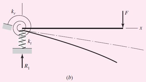
18 Example 4-4 Fig. 4 5
19 19 HW Assignment #4-2 Problems: 4.10, 4.14, 4.41 Due Wednesday 19/3/2014
20 20 Strain Energy External work done on elastic member while deforming it is transformed into strain energy, or potential energy. Strain energy = average force deflection
21 21 Some Common Strain Energy Formulas Axial loading, k = AE/l from Eq. (4-4), Torsional loading, k = GJ/l from Eq. (4-7)
22 22 Some Common Strain Energy Formulas Direct shear loading, Bending loading,
23 23 Some Common Strain Energy Formulas Transverse shear loading, C = modifier dependent on x-sectional shape

24 24 Some Common Strain Energy Formulas Table 4 1: Strain-Energy Correction Factors for Transverse Shear

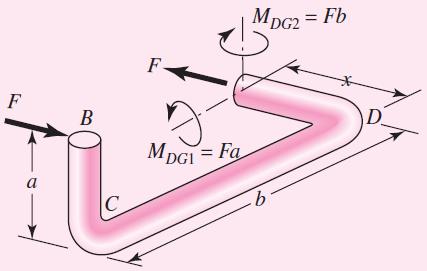
25 Example 4-8 A cantilever beam with a round cross section has a concentrated load F at the end, as shown in Fig. 4 9a. Find the strain energy in the beam. Fig. 4 9
26 26 Castigliano s Theorem Forces act on elastic systems subject to small displacements Displacement corresponding to any force along its direction = partial derivative of total strain energy wrt force For rotational displacement, in radians,
27 Example 4-9 The cantilever of Ex. 4 8 is a carbon steel bar 10 in long with a 1-in diameter and is loaded by a force F = 100 lbf. a. Find max deflection using Castigliano s theorem, including that due to shear. b. What error is introduced if shear is neglected? Fig. 4 9
28 28 Utilizing a Fictitious Force Apply a fictitious force Q at the point, and in the direction, of the desired deflection. Set up the equation for total strain energy including energy due to Q. Take derivative of total strain energy wrt Q Set Q to zero
29 29 Finding Deflection Without Finding Energy Partial derivative is moved inside the integral. For example, for bending,
30 Common Deflection Equations

31 Example 4-10 Using Castigliano s method, determine the deflections of points A and B due to the force F applied at the end of the step shaft shown in Fig The second area moments for sections AB and BC are I 1 and 2I 1, respectively. Fig. 4 10

32 Example 4-11 For the wire form of diameter d shown in Fig. 4 11a, determine the deflection of point B in the direction of the applied force F (neglect the effect of transverse shear). Fig. 4 11

33 Example 4-11
34 34 HW Assignment #4-3 Problems: 4.67, 4.70 Due Saturday 22/3/2014
35 35 Deflection of Curved Members Four strain energy terms due to: 1. Bending moment M 2. Axial force F q 3. Bending moment due to F q 4. Transverse shear F r
36 36 Deflection of Curved Members Strain energy due to bending moment M r n = radius of neutral axis
37 37 Deflection of Curved Members Strain energy due to axial force F q
38 38 Deflection of Curved Members Strain energy due to bending moment from F q
39 39 Deflection of Curved Members Strain energy due to transverse shear F r
40 40 Deflection of Curved Members Combining four energy terms Deflection by Castigliano s method

41 41 Deflection of Curved Members
42 42 Deflection of Curved Members
43 43 Deflection of Thin Curved Members R/h > 10, eccentricity is small Strain energies approximated with regular energy equations: Rdq dx As R increases, bending component dominates all other terms

44 Example 4-12 The cantilevered hook shown in Fig. 4 13a is formed from a round steel wire with a diameter of 2 mm. The hook dimensions are l = 40 & R = 50 mm. A force P of 1 N is applied at point C. Use Castigliano s theorem to estimate deflection at point D at the tip. Fig. 4 13
45 45 HW Assignment #4-4 Problems: 4.78 Due Monday 24/3/2014
46 46 Statically Indeterminate Problems Redundant supports: extra constraint supports A deflection equation is required for each redundant support.
47 47 Procedure 1 for Statically Indeterminate Problems 1. Choose redundant reactions 2. Write equations of static equilibrium for remaining reactions in terms of applied loads & redundant reactions. 3. Write deflection equations for points at locations of redundant reactions in terms of applied loads and redundant reactions. 4. Solve equilibrium & deflection equations
48 Example 4-14 The indeterminate beam 11 of Appendix Table A 9 is reproduced in Fig Determine the reactions using procedure 1. Fig. 4 16
49 49 Procedure 2 for Statically Indeterminate Problems 1. Write equations of static equilibrium in terms of applied loads & unknown restraint reactions. 2. Write deflection equation in terms of applied loads and unknown restraint reactions. 3. Apply boundary conditions to deflection equation consistent with restraints. 4. Solve the set of equations.
50 Example 4-15 The rods AD & CE shown in Fig. 4 17a each have a diameter of 10 mm. The second area moment of beam ABC is I = 62.5(10 3 ) mm 4. The modulus of elasticity of the material used for the rods and beam is E = 200 GPa. The threads at the ends of the rods are singlethreaded with a pitch of 1.5 mm. The nuts are first snugly fit with bar ABC horizontal. Next the nut at A is tightened one full turn. Determine the resulting tension in each rod and the deflections of points A and C.
51 Example 4-15 Fig. 4 17
52 52 HW Assignment #4-5 Problems: 4.95, 4.97 Due Wednesday 26/3/2014
53 53 Compression Members Column: A member loaded in compression either its length or eccentric loading causes it to experience more than pure compression
54 54 Compression Members Four categories of columns 1. Long columns with central loading 2. Intermediate-length columns with central loading 3. Columns with eccentric loading 4. Struts or short columns with eccentric loading
55 55 Long Columns with Central Loading When P reaches critical load, column becomes unstable & bending develops rapidly
56 56 Euler Column Formula Pin-ended column, Other end conditions: apply a constant C for each end condition

57 57 Recommended Values for End Condition Constant Table 4-2: End-Condition Constants for Euler Columns [to Be Used with Eq. (4 43)]
58 58 Long Columns with Central Loading I = Ak 2, Euler column formula becomes l/k = slenderness ratio, to classify columns according to length categories. P cr /A = critical unit load necessary to place the column in a condition of unstable equilibrium
59 Euler Curve 59 P cr /A vs l/k, with C = 1 gives curve PQR Fig. 4 19
60 60 Long Columns with Central Loading Vulnerability to failure near point Q Buckling is sudden & catastrophic, a conservative approach near Q is desired T is defined such that P cr /A = S y /2, giving
61 61 Condition for Use of Euler Equation (l/k) > (l/k) 1, use Euler equation (l/k) (l/k) 1, use a parabolic curve between S y & T
62 62 Intermediate-Length Columns with Central Loading Intermediate-length columns, (l/k) (l/k) 1, use a parabolic curve between S y and T General form of parabola
63 63 Intermediate-Length Columns with Central Loading If parabola starts at S y, then a = S y
64 64 Columns with Eccentric Loading M = -P(e+y) d 2 y/dx 2 =M/EI Fig. 4 20
65 65 Columns with Eccentric Loading Boundary conditions: y = 0 at x = 0 and at x = l
66 66 Columns with Eccentric Loading At midspan where x = l/2
67 67 Columns with Eccentric Loading Max compressive stress: Substituting M max from Eq. (4-48)
68 68 Columns with Eccentric Loading Using S yc as the maximum value of s c, and solving for P/A, we obtain the secant column formula
69 69 Secant Column Formula ec/k 2 = eccentricity ratio Fig. 4 21
70 Example 4-16 Develop specific Euler equations for the sizes of columns having a. Round cross sections b. Rectangular cross sections
71 Example 4-17 Specify the diameter of a round column 1.5 m long that is to carry a maximum load estimated to be 22 kn. Use a design factor n d = 4 and consider the ends as pinned (rounded). The column material selected has a minimum yield strength of 500 MPa and a modulus of elasticity of 207 GPa.
 For round columns, Eq. (4 46) yields (b) For round columns, Eq.")
72 Example 4-18 Repeat Ex for J. B. Johnson columns. (a) For round columns, Eq. (4 46) yields (b) For round columns, Eq. (4 46) yields
73 Example 4-19 Choose a set of dimensions for a rectangular link that is to carry a maximum compressive load of 5000 lbf. The material selected has a minimum yield strength of 75 kpsi and a modulus of elasticity E = 30 Mpsi. Use a design factor of 4 and an end condition constant C = 1 for buckling in the weakest direction, and design for a. a length of 15 in b. a length of 8 in with a minimum thickness of 0.5 in.
74 74 Struts or Short Compression Members Strut: short member loaded in compression If eccentricity exists, max stress is at B with axial compression and bending.
75 75 Struts or Short Compression Members Differs from secant equation in that it assumes small effect of bending deflection If bending deflection is limited to 1% of e, then from Eq. 4-44, the limiting slenderness ratio for strut is
76 Example 4-20 Figure 4 23a shows a workpiece clamped to a milling machine table by a bolt tightened to a tension of 2000 lbf. The clamp contact is offset from the centroidal axis of the strut by a distance e = 0.10 in, as shown in part b of the figure. The strut, or block, is steel, 1 in square and 4 in long, as shown. Determine the maximum compressive stress in the block.

77 Example 4-20 Fig. 4 23
78 78 HW Assignment #4-6 Problems: 4.107, Due Saturday 29/3/2014
79 79 Suddenly Applied Loading Weight falls from distance h and suddenly applies a load to a cantilever beam Find deflection and force applied to beam due to impact
80 80 Suddenly Applied Loading Abstract model considering beam as simple spring Table A-9: beam 1, k= F/y =3EI/l 3 Assume beam to be massless, so no momentum transfer, just energy transfer Loss of potential energy from change of elevation is W(h + d)
81 81 Suddenly Applied Loading Increase in potential energy from compressing spring is kd 2 /2 Conservation of energy W(h + d) = kd 2 /2

82 82 Suddenly Applied Loading Maximum deflection Maximum force
Lecture Slides. Chapter 4. Deflection and Stiffness. The McGraw-Hill Companies 2012
 Lecture Slides Chapter 4 Deflection and Stiffness The McGraw-Hill Companies 2012 Chapter Outline Force vs Deflection Elasticity property of a material that enables it to regain its original configuration
Chapter 4 Deflection and Stiffness
 Chapter 4 Deflection and Stiffness Asst. Prof. Dr. Supakit Rooppakhun Chapter Outline Deflection and Stiffness 4-1 Spring Rates 4-2 Tension, Compression, and Torsion 4-3 Deflection Due to Bending 4-4 Beam
Mechanical Design in Optical Engineering
 OPTI Buckling Buckling and Stability: As we learned in the previous lectures, structures may fail in a variety of ways, depending on the materials, load and support conditions. We had two primary concerns:
Mechanics of Materials II. Chapter III. A review of the fundamental formulation of stress, strain, and deflection
 Mechanics of Materials II Chapter III A review of the fundamental formulation of stress, strain, and deflection Outline Introduction Assumtions and limitations Axial loading Torsion of circular shafts
Chapter 5 Elastic Strain, Deflection, and Stability 1. Elastic Stress-Strain Relationship
 Chapter 5 Elastic Strain, Deflection, and Stability Elastic Stress-Strain Relationship A stress in the x-direction causes a strain in the x-direction by σ x also causes a strain in the y-direction & z-direction
D : SOLID MECHANICS. Q. 1 Q. 9 carry one mark each. Q.1 Find the force (in kn) in the member BH of the truss shown.
 in the member BH of the truss shown.") D : SOLID MECHANICS Q. 1 Q. 9 carry one mark each. Q.1 Find the force (in kn) in the member BH of the truss shown. Q.2 Consider the forces of magnitude F acting on the sides of the regular hexagon having
D : SOLID MECHANICS Q. 1 Q. 9 carry one mark each. Q.1 Find the force (in kn) in the member BH of the truss shown. Q.2 Consider the forces of magnitude F acting on the sides of the regular hexagon having
QUESTION BANK SEMESTER: III SUBJECT NAME: MECHANICS OF SOLIDS
 QUESTION BANK SEMESTER: III SUBJECT NAME: MECHANICS OF SOLIDS UNIT 1- STRESS AND STRAIN PART A (2 Marks) 1. Define longitudinal strain and lateral strain. 2. State Hooke s law. 3. Define modular ratio,
MAAE 2202 A. Come to the PASS workshop with your mock exam complete. During the workshop you can work with other students to review your work.
 It is most beneficial to you to write this mock final exam UNDER EXAM CONDITIONS. This means: Complete the exam in 3 hours. Work on your own. Keep your textbook closed. Attempt every question. After the
CE6306 STRENGTH OF MATERIALS TWO MARK QUESTIONS WITH ANSWERS ACADEMIC YEAR
 CE6306 STRENGTH OF MATERIALS TWO MARK QUESTIONS WITH ANSWERS ACADEMIC YEAR 2014-2015 UNIT - 1 STRESS, STRAIN AND DEFORMATION OF SOLIDS PART- A 1. Define tensile stress and tensile strain. The stress induced
Stress Analysis Lecture 3 ME 276 Spring Dr./ Ahmed Mohamed Nagib Elmekawy
 Stress Analysis Lecture 3 ME 276 Spring 2017-2018 Dr./ Ahmed Mohamed Nagib Elmekawy Axial Stress 2 Beam under the action of two tensile forces 3 Beam under the action of two tensile forces 4 Shear Stress
KINGS COLLEGE OF ENGINEERING DEPARTMENT OF MECHANICAL ENGINEERING QUESTION BANK. Subject code/name: ME2254/STRENGTH OF MATERIALS Year/Sem:II / IV
 KINGS COLLEGE OF ENGINEERING DEPARTMENT OF MECHANICAL ENGINEERING QUESTION BANK Subject code/name: ME2254/STRENGTH OF MATERIALS Year/Sem:II / IV UNIT I STRESS, STRAIN DEFORMATION OF SOLIDS PART A (2 MARKS)
Tuesday, February 11, Chapter 3. Load and Stress Analysis. Dr. Mohammad Suliman Abuhaiba, PE
 1 Chapter 3 Load and Stress Analysis 2 Chapter Outline Equilibrium & Free-Body Diagrams Shear Force and Bending Moments in Beams Singularity Functions Stress Cartesian Stress Components Mohr s Circle for
Mechanics of Materials Primer
 Mechanics of Materials rimer Notation: A = area (net = with holes, bearing = in contact, etc...) b = total width of material at a horizontal section d = diameter of a hole D = symbol for diameter E = modulus
EMA 3702 Mechanics & Materials Science (Mechanics of Materials) Chapter 10 Columns
 Chapter 10 Columns") EMA 370 Mechanics & Materials Science (Mechanics of Materials) Chapter 10 Columns Columns Introduction Columns are vertical prismatic members subjected to compressive forces Goals: 1. Study the stability
EMA 370 Mechanics & Materials Science (Mechanics of Materials) Chapter 10 Columns Columns Introduction Columns are vertical prismatic members subjected to compressive forces Goals: 1. Study the stability
Lecture 15 Strain and stress in beams
 Spring, 2019 ME 323 Mechanics of Materials Lecture 15 Strain and stress in beams Reading assignment: 6.1 6.2 News: Instructor: Prof. Marcial Gonzalez Last modified: 1/6/19 9:42:38 PM Beam theory (@ ME
MECHANICS OF MATERIALS
 STATICS AND MECHANICS OF MATERIALS Ferdinand P. Beer E. Russell Johnston, Jr, John T. DeWolf David E Mazurek \Cawect Mc / iur/» Craw SugomcT Hilt Introduction 1 1.1 What is Mechanics? 2 1.2 Fundamental
[8] Bending and Shear Loading of Beams
![[8] Bending and Shear Loading of Beams](/thumbs/92/110949676.jpg "[8] Bending and Shear Loading of Beams") [8] Bending and Shear Loading of Beams Page 1 of 28 [8] Bending and Shear Loading of Beams [8.1] Bending of Beams (will not be covered in class) [8.2] Bending Strain and Stress [8.3] Shear in Straight
[8] Bending and Shear Loading of Beams Page 1 of 28 [8] Bending and Shear Loading of Beams [8.1] Bending of Beams (will not be covered in class) [8.2] Bending Strain and Stress [8.3] Shear in Straight
QUESTION BANK DEPARTMENT: CIVIL SEMESTER: III SUBJECT CODE: CE2201 SUBJECT NAME: MECHANICS OF SOLIDS UNIT 1- STRESS AND STRAIN PART A
 DEPARTMENT: CIVIL SUBJECT CODE: CE2201 QUESTION BANK SEMESTER: III SUBJECT NAME: MECHANICS OF SOLIDS UNIT 1- STRESS AND STRAIN PART A (2 Marks) 1. Define longitudinal strain and lateral strain. 2. State
COURSE TITLE : APPLIED MECHANICS & STRENGTH OF MATERIALS COURSE CODE : 4017 COURSE CATEGORY : A PERIODS/WEEK : 6 PERIODS/ SEMESTER : 108 CREDITS : 5
 COURSE TITLE : APPLIED MECHANICS & STRENGTH OF MATERIALS COURSE CODE : 4017 COURSE CATEGORY : A PERIODS/WEEK : 6 PERIODS/ SEMESTER : 108 CREDITS : 5 TIME SCHEDULE MODULE TOPICS PERIODS 1 Simple stresses
Members Subjected to Torsional Loads
 Members Subjected to Torsional Loads Torsion of circular shafts Definition of Torsion: Consider a shaft rigidly clamped at one end and twisted at the other end by a torque T = F.d applied in a plane perpendicular
3. BEAMS: STRAIN, STRESS, DEFLECTIONS
 3. BEAMS: STRAIN, STRESS, DEFLECTIONS The beam, or flexural member, is frequently encountered in structures and machines, and its elementary stress analysis constitutes one of the more interesting facets
Assumptions: beam is initially straight, is elastically deformed by the loads, such that the slope and deflection of the elastic curve are
 *12.4 SLOPE & DISPLACEMENT BY THE MOMENT-AREA METHOD Assumptions: beam is initially straight, is elastically deformed by the loads, such that the slope and deflection of the elastic curve are very small,
Module 4 : Deflection of Structures Lecture 4 : Strain Energy Method
 Module 4 : Deflection of Structures Lecture 4 : Strain Energy Method Objectives In this course you will learn the following Deflection by strain energy method. Evaluation of strain energy in member under
PES Institute of Technology
 PES Institute of Technology Bangalore south campus, Bangalore-5460100 Department of Mechanical Engineering Faculty name : Madhu M Date: 29/06/2012 SEM : 3 rd A SEC Subject : MECHANICS OF MATERIALS Subject
Review of Strain Energy Methods and Introduction to Stiffness Matrix Methods of Structural Analysis
 uke University epartment of Civil and Environmental Engineering CEE 42L. Matrix Structural Analysis Henri P. Gavin Fall, 22 Review of Strain Energy Methods and Introduction to Stiffness Matrix Methods
needed to buckle an ideal column. Analyze the buckling with bending of a column. Discuss methods used to design concentric and eccentric columns.
 CHAPTER OBJECTIVES Discuss the behavior of columns. Discuss the buckling of columns. Determine the axial load needed to buckle an ideal column. Analyze the buckling with bending of a column. Discuss methods
: APPLIED MECHANICS & STRENGTH OF MATERIALS COURSE CODE : 4021 COURSE CATEGORY : A PERIODS/ WEEK : 5 PERIODS/ SEMESTER : 75 CREDIT : 5 TIME SCHEDULE
 COURSE TITLE : APPLIED MECHANICS & STRENGTH OF MATERIALS COURSE CODE : 4021 COURSE CATEGORY : A PERIODS/ WEEK : 5 PERIODS/ SEMESTER : 75 CREDIT : 5 TIME SCHEDULE MODULE TOPIC PERIODS 1 Simple stresses
Chapter 3. Load and Stress Analysis
 Chapter 3 Load and Stress Analysis 2 Shear Force and Bending Moments in Beams Internal shear force V & bending moment M must ensure equilibrium Fig. 3 2 Sign Conventions for Bending and Shear Fig. 3 3
INTRODUCTION TO STRAIN
 SIMPLE STRAIN INTRODUCTION TO STRAIN In general terms, Strain is a geometric quantity that measures the deformation of a body. There are two types of strain: normal strain: characterizes dimensional changes,
MECH 401 Mechanical Design Applications
 MECH 40 Mechanical Design Applications Dr. M. K. O Malley Master Notes Spring 008 Dr. D. M. McStravick Rice University Design Considerations Stress Deflection Strain Stiffness Stability Often the controlling
7.5 Elastic Buckling Columns and Buckling
 7.5 Elastic Buckling The initial theory of the buckling of columns was worked out by Euler in 1757, a nice example of a theory preceding the application, the application mainly being for the later invented
Methods of Analysis. Force or Flexibility Method
 INTRODUCTION: The structural analysis is a mathematical process by which the response of a structure to specified loads is determined. This response is measured by determining the internal forces or stresses
ε t increases from the compressioncontrolled Figure 9.15: Adjusted interaction diagram
 CHAPTER NINE COLUMNS 4 b. The modified axial strength in compression is reduced to account for accidental eccentricity. The magnitude of axial force evaluated in step (a) is multiplied by 0.80 in case
D : SOLID MECHANICS. Q. 1 Q. 9 carry one mark each.
 GTE 2016 Q. 1 Q. 9 carry one mark each. D : SOLID MECHNICS Q.1 single degree of freedom vibrating system has mass of 5 kg, stiffness of 500 N/m and damping coefficient of 100 N-s/m. To make the system
18.Define the term modulus of resilience. May/June Define Principal Stress. 20. Define Hydrostatic Pressure.
 CE6306 STREGNTH OF MATERIALS Question Bank Unit-I STRESS, STRAIN, DEFORMATION OF SOLIDS PART-A 1. Define Poison s Ratio May/June 2009 2. What is thermal stress? May/June 2009 3. Estimate the load carried
Purpose of this Guide: To thoroughly prepare students for the exact types of problems that will be on Exam 3.
 ES230 STRENGTH OF MTERILS Exam 3 Study Guide Exam 3: Wednesday, March 8 th in-class Updated 3/3/17 Purpose of this Guide: To thoroughly prepare students for the exact types of problems that will be on
COLUMNS: BUCKLING (DIFFERENT ENDS)
") COLUMNS: BUCKLING (DIFFERENT ENDS) Buckling of Long Straight Columns Example 4 Slide No. 1 A simple pin-connected truss is loaded and supported as shown in Fig. 1. All members of the truss are WT10 43
COLUMNS: BUCKLING (DIFFERENT ENDS) Buckling of Long Straight Columns Example 4 Slide No. 1 A simple pin-connected truss is loaded and supported as shown in Fig. 1. All members of the truss are WT10 43
Chapter 3. Load and Stress Analysis. Lecture Slides
 Lecture Slides Chapter 3 Load and Stress Analysis 2015 by McGraw Hill Education. This is proprietary material solely for authorized instructor use. Not authorized for sale or distribution in any manner.
MECHANICS OF SOLIDS. (For B.E. Mechanical Engineering Students) As per New Revised Syllabus of APJ Abdul Kalam Technological University
 As per New Revised Syllabus of APJ Abdul Kalam Technological University") MECHANICS OF SOLIDS (For B.E. Mechanical Engineering Students) As per New Revised Syllabus of APJ Abdul Kalam Technological University Dr. S.Ramachandran, M.E., Ph.D., Mr. V.J. George, M.E., Mr. S. Kumaran,
MECHANICS OF SOLIDS (For B.E. Mechanical Engineering Students) As per New Revised Syllabus of APJ Abdul Kalam Technological University Dr. S.Ramachandran, M.E., Ph.D., Mr. V.J. George, M.E., Mr. S. Kumaran,
Engineering Science OUTCOME 1 - TUTORIAL 4 COLUMNS
 Unit 2: Unit code: QCF Level: Credit value: 15 Engineering Science L/601/10 OUTCOME 1 - TUTORIAL COLUMNS 1. Be able to determine the behavioural characteristics of elements of static engineering systems
CHAPTER 5. Beam Theory
 CHPTER 5. Beam Theory SangJoon Shin School of Mechanical and erospace Engineering Seoul National University ctive eroelasticity and Rotorcraft Lab. 5. The Euler-Bernoulli assumptions One of its dimensions
[5] Stress and Strain
![[5] Stress and Strain](/thumbs/95/123344550.jpg "[5] Stress and Strain") [5] Stress and Strain Page 1 of 34 [5] Stress and Strain [5.1] Internal Stress of Solids [5.2] Design of Simple Connections (will not be covered in class) [5.3] Deformation and Strain [5.4] Hooke s Law
[5] Stress and Strain Page 1 of 34 [5] Stress and Strain [5.1] Internal Stress of Solids [5.2] Design of Simple Connections (will not be covered in class) [5.3] Deformation and Strain [5.4] Hooke s Law
CHAPTER -6- BENDING Part -1-
 Ishik University / Sulaimani Civil Engineering Department Mechanics of Materials CE 211 CHAPTER -6- BENDING Part -1-1 CHAPTER -6- Bending Outlines of this chapter: 6.1. Chapter Objectives 6.2. Shear and
PDDC 1 st Semester Civil Engineering Department Assignments of Mechanics of Solids [ ] Introduction, Fundamentals of Statics
![PDDC 1 st Semester Civil Engineering Department Assignments of Mechanics of Solids [ ] Introduction, Fundamentals of Statics](/thumbs/92/109382806.jpg "PDDC 1 st Semester Civil Engineering Department Assignments of Mechanics of Solids [ ] Introduction, Fundamentals of Statics") Page1 PDDC 1 st Semester Civil Engineering Department Assignments of Mechanics of Solids [2910601] Introduction, Fundamentals of Statics 1. Differentiate between Scalar and Vector quantity. Write S.I.
Page1 PDDC 1 st Semester Civil Engineering Department Assignments of Mechanics of Solids [2910601] Introduction, Fundamentals of Statics 1. Differentiate between Scalar and Vector quantity. Write S.I.
R13. II B. Tech I Semester Regular Examinations, Jan MECHANICS OF SOLIDS (Com. to ME, AME, AE, MTE) PART-A
 PART-A") SET - 1 II B. Tech I Semester Regular Examinations, Jan - 2015 MECHANICS OF SOLIDS (Com. to ME, AME, AE, MTE) Time: 3 hours Max. Marks: 70 Note: 1. Question Paper consists of two parts (Part-A and Part-B)
SET - 1 II B. Tech I Semester Regular Examinations, Jan - 2015 MECHANICS OF SOLIDS (Com. to ME, AME, AE, MTE) Time: 3 hours Max. Marks: 70 Note: 1. Question Paper consists of two parts (Part-A and Part-B)
UNIT 1 STRESS STRAIN AND DEFORMATION OF SOLIDS, STATES OF STRESS 1. Define stress. When an external force acts on a body, it undergoes deformation.
 UNIT 1 STRESS STRAIN AND DEFORMATION OF SOLIDS, STATES OF STRESS 1. Define stress. When an external force acts on a body, it undergoes deformation. At the same time the body resists deformation. The magnitude
Comb resonator design (2)
") Lecture 6: Comb resonator design () -Intro Intro. to Mechanics of Materials School of Electrical l Engineering i and Computer Science, Seoul National University Nano/Micro Systems & Controls Laboratory
Lecture 6: Comb resonator design () -Intro Intro. to Mechanics of Materials School of Electrical l Engineering i and Computer Science, Seoul National University Nano/Micro Systems & Controls Laboratory
UNIT IV FLEXIBILTY AND STIFFNESS METHOD
 SIDDHARTH GROUP OF INSTITUTIONS :: PUTTUR Siddharth Nagar, Narayanavanam Road 517583 QUESTION BANK (DESCRIPTIVE) Subject with Code : SA-II (13A01505) Year & Sem: III-B.Tech & I-Sem Course & Branch: B.Tech
SRI CHANDRASEKHARENDRA SARASWATHI VISWA MAHAVIDHYALAYA
 SRI CHANDRASEKHARENDRA SARASWATHI VISWA MAHAVIDHYALAYA (Declared as Deemed-to-be University under Section 3 of the UGC Act, 1956, Vide notification No.F.9.9/92-U-3 dated 26 th May 1993 of the Govt. of
MECHANICS OF MATERIALS
 Third E CHAPTER 2 Stress MECHANICS OF MATERIALS Ferdinand P. Beer E. Russell Johnston, Jr. John T. DeWolf Lecture Notes: J. Walt Oler Texas Tech University and Strain Axial Loading Contents Stress & Strain:
SAULT COLLEGE OF APPLIED ARTS & TECHNOLOGY SAULT STE. MARIE, ONTARIO COURSE OUTLINE STRENGTH OF MATERIALS MECHANICAL TECHNOLOGY
 (/.- SAULT COLLEGE OF APPLIED ARTS & TECHNOLOGY SAULT STE. MARIE, ONTARIO COURSE OUTLINE Course Title: Code No.: Program: Semester: Date: Author: STRENGTH OF MATERIALS MCH 202 MECHANICAL TECHNOLOGY THREE
Unit III Theory of columns. Dr.P.Venkateswara Rao, Associate Professor, Dept. of Civil Engg., SVCE, Sriperumbudir
 Unit III Theory of columns 1 Unit III Theory of Columns References: Punmia B.C.,"Theory of Structures" (SMTS) Vol II, Laxmi Publishing Pvt Ltd, New Delhi 2004. Rattan.S.S., "Strength of Materials", Tata
CHAPTER 4: BENDING OF BEAMS
 (74) CHAPTER 4: BENDING OF BEAMS This chapter will be devoted to the analysis of prismatic members subjected to equal and opposite couples M and M' acting in the same longitudinal plane. Such members are
Elastic Stability Of Columns
 Elastic Stability Of Columns Introduction: Structural members which carry compressive loads may be divided into two broad categories depending on their relative lengths and cross-sectional dimensions.
DEPARTMENT OF CIVIL ENGINEERING
 KINGS COLLEGE OF ENGINEERING DEPARTMENT OF CIVIL ENGINEERING SUBJECT: CE 2252 STRENGTH OF MATERIALS UNIT: I ENERGY METHODS 1. Define: Strain Energy When an elastic body is under the action of external
Downloaded from Downloaded from / 1
 PURWANCHAL UNIVERSITY III SEMESTER FINAL EXAMINATION-2002 LEVEL : B. E. (Civil) SUBJECT: BEG256CI, Strength of Material Full Marks: 80 TIME: 03:00 hrs Pass marks: 32 Candidates are required to give their
INSTITUTE OF AERONAUTICAL ENGINEERING (Autonomous) Dundigal, Hyderabad
 Dundigal, Hyderabad") INSTITUTE OF AERONAUTICAL ENGINEERING (Autonomous) Dundigal, Hyderabad -00 04 CIVIL ENGINEERING QUESTION BANK Course Name : STRENGTH OF MATERIALS II Course Code : A404 Class : II B. Tech II Semester Section
INSTITUTE OF AERONAUTICAL ENGINEERING (Autonomous) Dundigal, Hyderabad -00 04 CIVIL ENGINEERING QUESTION BANK Course Name : STRENGTH OF MATERIALS II Course Code : A404 Class : II B. Tech II Semester Section
The University of Melbourne Engineering Mechanics
 The University of Melbourne 436-291 Engineering Mechanics Tutorial Four Poisson s Ratio and Axial Loading Part A (Introductory) 1. (Problem 9-22 from Hibbeler - Statics and Mechanics of Materials) A short
STRESS STRAIN AND DEFORMATION OF SOLIDS, STATES OF STRESS
 1 UNIT I STRESS STRAIN AND DEFORMATION OF SOLIDS, STATES OF STRESS 1. Define: Stress When an external force acts on a body, it undergoes deformation. At the same time the body resists deformation. The
Mechanics of Solids. Mechanics Of Solids. Suraj kr. Ray Department of Civil Engineering
 Mechanics Of Solids Suraj kr. Ray (surajjj2445@gmail.com) Department of Civil Engineering 1 Mechanics of Solids is a branch of applied mechanics that deals with the behaviour of solid bodies subjected
ME Final Exam. PROBLEM NO. 4 Part A (2 points max.) M (x) y. z (neutral axis) beam cross-sec+on. 20 kip ft. 0.2 ft. 10 ft. 0.1 ft.
 M (x) y. z (neutral axis) beam cross-sec+on. 20 kip ft. 0.2 ft. 10 ft. 0.1 ft.") ME 323 - Final Exam Name December 15, 2015 Instructor (circle) PROEM NO. 4 Part A (2 points max.) Krousgrill 11:30AM-12:20PM Ghosh 2:30-3:20PM Gonzalez 12:30-1:20PM Zhao 4:30-5:20PM M (x) y 20 kip ft 0.2
ME 323 - Final Exam Name December 15, 2015 Instructor (circle) PROEM NO. 4 Part A (2 points max.) Krousgrill 11:30AM-12:20PM Ghosh 2:30-3:20PM Gonzalez 12:30-1:20PM Zhao 4:30-5:20PM M (x) y 20 kip ft 0.2
Structural Dynamics Lecture Eleven: Dynamic Response of MDOF Systems: (Chapter 11) By: H. Ahmadian
 By: H. Ahmadian") Structural Dynamics Lecture Eleven: Dynamic Response of MDOF Systems: (Chapter 11) By: H. Ahmadian ahmadian@iust.ac.ir Dynamic Response of MDOF Systems: Mode-Superposition Method Mode-Superposition Method:
Structural Dynamics Lecture Eleven: Dynamic Response of MDOF Systems: (Chapter 11) By: H. Ahmadian ahmadian@iust.ac.ir Dynamic Response of MDOF Systems: Mode-Superposition Method Mode-Superposition Method:
2. Determine the deflection at C of the beam given in fig below. Use principal of virtual work. W L/2 B A L C
 CE-1259, Strength of Materials UNIT I STRESS, STRAIN DEFORMATION OF SOLIDS Part -A 1. Define strain energy density. 2. State Maxwell s reciprocal theorem. 3. Define proof resilience. 4. State Castigliano
If the number of unknown reaction components are equal to the number of equations, the structure is known as statically determinate.
 1 of 6 EQUILIBRIUM OF A RIGID BODY AND ANALYSIS OF ETRUCTURAS II 9.1 reactions in supports and joints of a two-dimensional structure and statically indeterminate reactions: Statically indeterminate structures
Consider an elastic spring as shown in the Fig.2.4. When the spring is slowly
 .3 Strain Energy Consider an elastic spring as shown in the Fig..4. When the spring is slowly pulled, it deflects by a small amount u 1. When the load is removed from the spring, it goes back to the original
Stress Analysis Lecture 4 ME 276 Spring Dr./ Ahmed Mohamed Nagib Elmekawy
 Stress Analysis Lecture 4 ME 76 Spring 017-018 Dr./ Ahmed Mohamed Nagib Elmekawy Shear and Moment Diagrams Beam Sign Convention The positive directions are as follows: The internal shear force causes a
PERIYAR CENTENARY POLYTECHNIC COLLEGE PERIYAR NAGAR - VALLAM THANJAVUR. DEPARTMENT OF MECHANICAL ENGINEERING QUESTION BANK
 PERIYAR CENTENARY POLYTECHNIC COLLEGE PERIYAR NAGAR - VALLAM - 613 403 - THANJAVUR. DEPARTMENT OF MECHANICAL ENGINEERING QUESTION BANK Sub : Strength of Materials Year / Sem: II / III Sub Code : MEB 310
FINAL EXAMINATION. (CE130-2 Mechanics of Materials)
") UNIVERSITY OF CLIFORNI, ERKELEY FLL SEMESTER 001 FINL EXMINTION (CE130- Mechanics of Materials) Problem 1: (15 points) pinned -bar structure is shown in Figure 1. There is an external force, W = 5000N,
UNIVERSITY OF CLIFORNI, ERKELEY FLL SEMESTER 001 FINL EXMINTION (CE130- Mechanics of Materials) Problem 1: (15 points) pinned -bar structure is shown in Figure 1. There is an external force, W = 5000N,
Critical Load columns buckling critical load
 Buckling of Columns Buckling of Columns Critical Load Some member may be subjected to compressive loadings, and if these members are long enough to cause the member to deflect laterally or sideway. To
FLEXIBILITY METHOD FOR INDETERMINATE FRAMES
 UNIT - I FLEXIBILITY METHOD FOR INDETERMINATE FRAMES 1. What is meant by indeterminate structures? Structures that do not satisfy the conditions of equilibrium are called indeterminate structure. These
71- Laxmi Nagar (South), Niwaru Road, Jhotwara, Jaipur ,India. Phone: Mob. : /
, Niwaru Road, Jhotwara, Jaipur ,India. Phone: Mob. : /") www.aarekh.com 71- Laxmi Nagar (South), Niwaru Road, Jhotwara, Jaipur 302 012,India. Phone: 0141-2348647 Mob. : +91-9799435640 / 9166936207 1. Limiting values of poisson s ratio are (a) -1 and 0.5 (b)
www.aarekh.com 71- Laxmi Nagar (South), Niwaru Road, Jhotwara, Jaipur 302 012,India. Phone: 0141-2348647 Mob. : +91-9799435640 / 9166936207 1. Limiting values of poisson s ratio are (a) -1 and 0.5 (b)
Advanced Structural Analysis EGF Section Properties and Bending
 Advanced Structural Analysis EGF316 3. Section Properties and Bending 3.1 Loads in beams When we analyse beams, we need to consider various types of loads acting on them, for example, axial forces, shear
CHAPTER 5 Statically Determinate Plane Trusses
 CHAPTER 5 Statically Determinate Plane Trusses TYPES OF ROOF TRUSS TYPES OF ROOF TRUSS ROOF TRUSS SETUP ROOF TRUSS SETUP OBJECTIVES To determine the STABILITY and DETERMINACY of plane trusses To analyse
CHAPTER 5 Statically Determinate Plane Trusses TYPES OF ROOF TRUSS
 CHAPTER 5 Statically Determinate Plane Trusses TYPES OF ROOF TRUSS 1 TYPES OF ROOF TRUSS ROOF TRUSS SETUP 2 ROOF TRUSS SETUP OBJECTIVES To determine the STABILITY and DETERMINACY of plane trusses To analyse
Sample Question Paper
 Scheme I Sample Question Paper Program Name : Mechanical Engineering Program Group Program Code : AE/ME/PG/PT/FG Semester : Third Course Title : Strength of Materials Marks : 70 Time: 3 Hrs. Instructions:
Only for Reference Page 1 of 18
 Only for Reference www.civilpddc2013.weebly.com Page 1 of 18 Seat No.: Enrolment No. GUJARAT TECHNOLOGICAL UNIVERSITY PDDC - SEMESTER II EXAMINATION WINTER 2013 Subject Code: X20603 Date: 26-12-2013 Subject
UNIT-I STRESS, STRAIN. 1. A Member A B C D is subjected to loading as shown in fig determine the total elongation. Take E= 2 x10 5 N/mm 2
 UNIT-I STRESS, STRAIN 1. A Member A B C D is subjected to loading as shown in fig determine the total elongation. Take E= 2 x10 5 N/mm 2 Young s modulus E= 2 x10 5 N/mm 2 Area1=900mm 2 Area2=400mm 2 Area3=625mm
2 marks Questions and Answers
 1. Define the term strain energy. A: Strain Energy of the elastic body is defined as the internal work done by the external load in deforming or straining the body. 2. Define the terms: Resilience and
MECE 3321: Mechanics of Solids Chapter 6
 MECE 3321: Mechanics of Solids Chapter 6 Samantha Ramirez Beams Beams are long straight members that carry loads perpendicular to their longitudinal axis Beams are classified by the way they are supported
ME 323 Examination #2 April 11, 2018
 ME 2 Eamination #2 April, 2 PROBLEM NO. 25 points ma. A thin-walled pressure vessel is fabricated b welding together two, open-ended stainless-steel vessels along a 6 weld line. The welded vessel has an
Chapter 2: Deflections of Structures
 Chapter 2: Deflections of Structures Fig. 4.1. (Fig. 2.1.) ASTU, Dept. of C Eng., Prepared by: Melkamu E. Page 1 (2.1) (4.1) (2.2) Fig.4.2 Fig.2.2 ASTU, Dept. of C Eng., Prepared by: Melkamu E. Page 2
OUTCOME 1 - TUTORIAL 3 BENDING MOMENTS. You should judge your progress by completing the self assessment exercises. CONTENTS
 Unit 2: Unit code: QCF Level: 4 Credit value: 15 Engineering Science L/601/1404 OUTCOME 1 - TUTORIAL 3 BENDING MOMENTS 1. Be able to determine the behavioural characteristics of elements of static engineering
NAME: Given Formulae: Law of Cosines: Law of Sines:
 NME: Given Formulae: Law of Cosines: EXM 3 PST PROBLEMS (LESSONS 21 TO 28) 100 points Thursday, November 16, 2017, 7pm to 9:30, Room 200 You are allowed to use a calculator and drawing equipment, only.
CIVIL DEPARTMENT MECHANICS OF STRUCTURES- ASSIGNMENT NO 1. Brach: CE YEAR:
 MECHANICS OF STRUCTURES- ASSIGNMENT NO 1 SEMESTER: V 1) Find the least moment of Inertia about the centroidal axes X-X and Y-Y of an unequal angle section 125 mm 75 mm 10 mm as shown in figure 2) Determine
Sub. Code:
 Important Instructions to examiners: ) The answers should be examined by key words and not as word-to-word as given in the model answer scheme. ) The model answer and the answer written by candidate may
675(1*7+ 2) 0$7(5,$/6
 0$7(5,$/6") 675(1*7+ 2) 0$7(5,$/6 (MECHANICS OF SOLIDS) (As per Leading Universities Latest syllabus including Anna University R2013 syllabus) Dr. S.Ramachandran, Professor and Research Head Faculty of Mechanical
675(1*7+ 2) 0$7(5,$/6 (MECHANICS OF SOLIDS) (As per Leading Universities Latest syllabus including Anna University R2013 syllabus) Dr. S.Ramachandran, Professor and Research Head Faculty of Mechanical
IDE 110 Mechanics of Materials Spring 2006 Final Examination FOR GRADING ONLY
 Spring 2006 Final Examination STUDENT S NAME (please print) STUDENT S SIGNATURE STUDENT NUMBER IDE 110 CLASS SECTION INSTRUCTOR S NAME Do not turn this page until instructed to start. Write your name on
Chapter 12 Elastic Stability of Columns
 Chapter 12 Elastic Stability of Columns Axial compressive loads can cause a sudden lateral deflection (Buckling) For columns made of elastic-perfectly plastic materials, P cr Depends primarily on E and
MECHANICS OF MATERIALS
 CHATR Stress MCHANICS OF MATRIALS and Strain Axial Loading Stress & Strain: Axial Loading Suitability of a structure or machine may depend on the deformations in the structure as well as the stresses induced
1-1 Locate the centroid of the plane area shown. 1-2 Determine the location of centroid of the composite area shown.
 Chapter 1 Review of Mechanics of Materials 1-1 Locate the centroid of the plane area shown 650 mm 1000 mm 650 x 1- Determine the location of centroid of the composite area shown. 00 150 mm radius 00 mm
EMA 3702 Mechanics & Materials Science (Mechanics of Materials) Chapter 2 Stress & Strain - Axial Loading
 Chapter 2 Stress & Strain - Axial Loading") MA 3702 Mechanics & Materials Science (Mechanics of Materials) Chapter 2 Stress & Strain - Axial Loading MA 3702 Mechanics & Materials Science Zhe Cheng (2018) 2 Stress & Strain - Axial Loading Statics
MA 3702 Mechanics & Materials Science (Mechanics of Materials) Chapter 2 Stress & Strain - Axial Loading MA 3702 Mechanics & Materials Science Zhe Cheng (2018) 2 Stress & Strain - Axial Loading Statics
Chapter 1 General Introduction Instructor: Dr. Mürüde Çelikağ Office : CE Building Room CE230 and GE241
 CIVL222 STRENGTH OF MATERIALS Chapter 1 General Introduction Instructor: Dr. Mürüde Çelikağ Office : CE Building Room CE230 and GE241 E-mail : murude.celikag@emu.edu.tr 1. INTRODUCTION There are three
Using the finite element method of structural analysis, determine displacements at nodes 1 and 2.
 Question 1 A pin-jointed plane frame, shown in Figure Q1, is fixed to rigid supports at nodes and 4 to prevent their nodal displacements. The frame is loaded at nodes 1 and by a horizontal and a vertical
[7] Torsion. [7.1] Torsion. [7.2] Statically Indeterminate Torsion. [7] Torsion Page 1 of 21
![[7] Torsion. [7.1] Torsion. [7.2] Statically Indeterminate Torsion. [7] Torsion Page 1 of 21](/thumbs/88/115835122.jpg "[7] Torsion. [7.1] Torsion. [7.2] Statically Indeterminate Torsion. [7] Torsion Page 1 of 21") [7] Torsion Page 1 of 21 [7] Torsion [7.1] Torsion [7.2] Statically Indeterminate Torsion [7] Torsion Page 2 of 21 [7.1] Torsion SHEAR STRAIN DUE TO TORSION 1) A shaft with a circular cross section is
[7] Torsion Page 1 of 21 [7] Torsion [7.1] Torsion [7.2] Statically Indeterminate Torsion [7] Torsion Page 2 of 21 [7.1] Torsion SHEAR STRAIN DUE TO TORSION 1) A shaft with a circular cross section is
ENG1001 Engineering Design 1
 ENG1001 Engineering Design 1 Structure & Loads Determine forces that act on structures causing it to deform, bend, and stretch Forces push/pull on objects Structures are loaded by: > Dead loads permanent
STRENGTH OF MATERIALS-I. Unit-1. Simple stresses and strains
 STRENGTH OF MATERIALS-I Unit-1 Simple stresses and strains 1. What is the Principle of surveying 2. Define Magnetic, True & Arbitrary Meridians. 3. Mention different types of chains 4. Differentiate between
Problem d d d B C E D. 0.8d. Additional lecturebook examples 29 ME 323
 Problem 9.1 Two beam segments, AC and CD, are connected together at C by a frictionless pin. Segment CD is cantilevered from a rigid support at D, and segment AC has a roller support at A. a) Determine
5. What is the moment of inertia about the x - x axis of the rectangular beam shown?
 1 of 5 Continuing Education Course #274 What Every Engineer Should Know About Structures Part D - Bending Strength Of Materials NOTE: The following question was revised on 15 August 2018 1. The moment
NORMAL STRESS. The simplest form of stress is normal stress/direct stress, which is the stress perpendicular to the surface on which it acts.
 NORMAL STRESS The simplest form of stress is normal stress/direct stress, which is the stress perpendicular to the surface on which it acts. σ = force/area = P/A where σ = the normal stress P = the centric
Structural Analysis Laboratory. Michael Storaker, Sam Davey and Rhys Witt. JEE 332 Structural Analysis. 4 June 2012.
 Structural Analysis Laboratory Michael Storaker, Sam Davey and Rhys Witt JEE 332 Structural Analysis 4 June 2012 Lecturer/Tutor Shinsuke Matsuarbara 1 Contents Statically Indeterminate Structure Objective...