MECH 401 Mechanical Design Applications
|
|
|
- Samson Owens
- 6 years ago
- Views:
Transcription
1 MECH 401 Mechanical Design Applications Dr. M. O Malley Master Notes Spring 008 Dr. D. M. McStravick Rice University
2 Updates HW 1 due Thursday ( ) Last time Introduction Units Reliability engineering Materials This week Load and stress analysis Quiz #1 is Jan 9 (in class) Covers material through Chapter 3 (first weeks of class)
3 Equilibrium Basic equations of equilibrium enable determination of unknown loads on a body For a body at rest, (recalling from statics) ΣF 0 ΣM 0 For a body in motion, (recalling from dynamics) ΣF ma ΣM Iα
4 Determining loads Machine and structural components are load-carrying members We need to be able to analyze these loads in order to design components for the proper conditions Determining loads Engines/compressors operate at known torques and speeds (easy!) Airplane structure loads depend on air turbulence, pilot decisions (not so easy) Experimental methods / past performance Often we can determine loads by using a free body diagram (FBD) Gives a concise view of all the forces acting on a rigid body
5 Steps for drawing FBD s 1. Choose your body and detach it from all other bodies and the ground sketch the contour. Show all external forces From ground From other bodies Include the weight of the body acting at the center of gravity (CG) 3. Be sure to properly indicate magnitude and direction Forces acting on the body, not by the body 4. Draw unknown external forces Typically reaction forces at ground contacts Recall that reaction forces constrain the body and occur at supports and connections 5. Include important dimensions
6 Example Drawing FBD s Fixed crane has mass of 1000 kg Used to lift a 400 kg crate Find: Determine the reaction forces at A and B CG 1.5 m A 400 kg B m 4m A-Pin-Rxforces B - Rocker - 1 Rx force
7 Crane example (FBD s) cont. CG 1.5 m A B m 4m 400 kg A-Pin-Rxforces B - Rocker - 1 Rx force 1. Choose your body and detach it from all other bodies and the ground sketch the contour. Show all external forces (from ground, from other bodies). Include weight of the body acting at the center of gravity (CG) 3. Be sure to properly indicate magnitude and direction (acting ON the body, not BY the body)
8 Crane example (FBD s) cont. CG 1.5 m A 400 kg Ay 400 kg B m 4m A-Pin-Rxforces B - Rocker - 1 Rx force Ax 1000 kg 4. Draw unknown external forces (typically reaction forces at ground contacts). Recall that reaction forces constrain the body and occur at supports and connections 5. Include important dimensions 1.5 m B Ay Ax B m (400 kg)(9.81 m/s ) 3.5 kn W (1000 kg)(9.81 m/s ) 9.81 kn 4m
9 Find A x, A y, and B ΣF x 0 ΣF y 0 ΣM 0 Find B: ΣM A 0 B(1.5) (9.81)() (3.5)(6) 0 B kn Which forces contribute to ΣM A? B, 9.81, 3.5 Which forces contribute to ΣF X? A x, B Which forces contribute to ΣF y? A y, 9.81, 3.5 Find A x : ΣFx 0 A x + B 0 A x kn A x kn 1.5 m Ax B Ay (400 kg)(9.81 m/s ) 3.5 kn W (1000 kg)(9.81 m/s )9.81kN Find A y : ΣFy 0 A y A y 33.3 kn m 4m
10 3-D Equilibrium example transmission belts pass over sheaves welded to an axle supported by bearings at B and D A radius.5 C radius Rotates at constant speed Find T and the reaction forces at B, D Assumptions: Bearing at D exerts no axial thrust Neglect weights of sheaves and axle
11 Draw FBD Detach the body from ground (bearings at B and D) Insert appropriate reaction forces 4 lb 18 lb B z B y D z 30 lb T D y
12 Solve for reaction forces for each axis If we sum moments about x (along the shaft), what forces are involved? 4lb, 18lb, 30 lb, T If we sum moments about y, what forces are involved? 4lb, 18lb, D z 4 lb If we sum moments about z, what forces are involved? 30lb, T, D y 18 lb B z B y D z If we sum forces in y, what forces will we need to consider? B y, 30lb, T, D y 30 lb T D y If we sum forces in Z, what forces do we need to consider? 4lb, 18lb, B z, D z
j (70 lb)k D (33.")
13 Solve for reaction forces for each axis ΣM x 0 (4)(.5) 18(.5) + 30() T() T 37.5 lb ΣM y 0 (4)(8) + (18)(8) D z (1) D z 8 lb ΣM z 0 -(30)(6) (37.5)(6) + D y (1) D y lb 4 lb ΣF y 0 B y D y B y + D y 67.5 B y lb 18 lb B z B y D z ΣF z B z + D z 4 + D z B z B z 70 lb 30 lb T D y B (33.75 lb)j (70 lb)k D (33.75 lb)j + (8 lb)k
14 Linearly Elastic Material Behavior Some linearly elastic materials: Metals Wood Concrete Plastic Ceramic and glass Linearly elastic materials obey Hooke s Laws!
15 Uniaxial Stress State Hooke s Law in uniaxial tension-compression: σ x Eε x Also, for isotropic and homogenous material Poisson s Ratio y x x x ν -ε y / ε x 0 (cork) < ν < 0.5 (rubber)
16 Thermal Stresses Expansion of Parts due to temperature without constraint no stresses with constraint stress buildup Expansion of a rod vs. a hole Differential Thermal Expansion Two material with differential thermal expansion rates that are bound together Brass and steel Metals vs. plastic
17 Hooke s Law for Shear τ Gγ G? Shear Modulus Modulus of Rigidity Note: No equivalent to Poisson for shear (no coupling between axes) yx xy
18 Relating E and G G E (1 + ν ) For linearly elastic, homogenous, isotropic material characterized by TWO independent parameters
19 Hooke s Law for Biaxial Stress State y ε x σ x E σ y ν E x xy x ε y σ E y σ x ν E yx y τ γ xy G xy
20 Hooke s Law for triaxial state of stress Most general case of static loading Coupled: zy yz zx y yx xy xz x ( ) σ x ν ε x σ y + σ z E E σ y ν ε y x + E E σ E ν E ( σ σ ) z ( σ σ ) z ε z x + y z Decoupled: Note: G E (1 + ν ) τ γ xy G xy τ xz γ xz G τ γ yz G yz
21 More on Hooke s Law Used to relate loading to stress state through geometry Analytical solutions for classical forms of loading Axial cases: Column in tension (trivial) Column in compression (non-trivial) We ll do this later Other cases: Beam in pure bending Beam in bending and shear Shaft in torsion
22 Column in tension Uniaxial tension σ F A Hooke s Law ε ε x ε z y σ E y ν F EA F EA
23 Beam in pure bending What does PURE mean? Moment is constant along the beam Other assumptions Symmetric cross-section Uniform along the length of the beam Linearly elastic Homogenous Constant properties throughout Isotropic Equal physical properties along each axis Enable geometric arguments Enable the use of Hooke s Law to relate geometry (ε) to stress (σ)
 from the neutral axis (at y 0) If homogenous (E constant), neutral axis passes through the centroid Uniaxial tension: ε ε x y ε My EI z ν My EI M Z (section modulus) I z A y")
24 Beam in pure bending Result Mc σ x I z I Z c I is the area moment of inertia: M is the applied bending moment c is the point of interest for stress analysis, a distance (usually y max ) from the neutral axis (at y 0) If homogenous (E constant), neutral axis passes through the centroid Uniaxial tension: ε ε x y ε My EI z ν My EI M Z (section modulus) I z A y da

25 Example Beam with rectangular cross-section
26 Beam in pure bending example, cont.
27 Example Find the maximum tensile and compressive stresses in the I-beam Beam in pure bending -- Mc σ I
28 Review of centroids Recall Parallel Axis Theorem I I + c Ad I is the moment of inertia about any point I c is moment of inertia about the centroid A is area of section d is distance from section centroid to axis of I
29 Example, cont. Recall: c and I defined with respect to the neutral axis (NA) First, we ll need to find I So We need to find the neutral axis Assume the I-beam is homogenous NA passes through the centroid of the cross-section
30 Finding the centroid Neutral axis passes through the centroid of the cross-sectional area Divide into simple-shaped sections to find the centroid of a composite area y y i A A i i y ( h )( ) ( h hb + + h)( hb) 4 3 3hb + hb 3 4 h
31 Finding I Moment of Inertia Red dot shows centroid of the composite area that we just found Similarly, we can find the moment of inertia of a composite area I I z I I i yellow z + I blue Use parallel axis theorem to find I for the blue and yellow areas Moment of inertia about a different point is the moment of inertia of the section about its centroid plus the area of the section times square of the distance to the point I Ic + Ad
32 Finding I Moment of Inertia, cont. I ( 6b)( h ) 3 yellow + 1 ()( b h) ( )( h ) 3 3hb bh 43 4 ( )( 3 ) 3 hb h bh I blue I I I blue + yellow 15 bh 48 3
 to the neutral axis Total height of cross-section h + h/ 10h/4 Neutral axis is at")
33 Finding the bending stresses Maximum tensile stress occurs at the base 3 Mc M ( 4 h) 36 M σ base 3 15 I bh 15 bh Maximum compressive stress occurs at the top 48 7 ( h) Mc M 4 15 bh 84 M 15 bh σ top 3 I 48 Note, y is the distance from the point of interest (top or base) to the neutral axis Total height of cross-section h + h/ 10h/4 Neutral axis is at 3h/4
34 Beams in bending and shear Assumptions for the analytical solution: σ x Mc / I holds even when moment is not constant along the length of the beam τ xy is constant across the width
35 Calculating the shear stress for beams in bending V(x) shear force I I z area moment of inertia about NA (neutral axis) b(y) width of beam Q ( y) A yda τ xy VQ Ib Where A is the area between yy and the top (or bottom) of the beam cross-section General observations about Q: Q is 0 at the top and bottom of the beam Q is maximum at the neutral axis τ 0 at top and bottom of cross-section τ max at neutral axis Note, V and b can be functions of y
36 Usually we have common cross-sections τ max for common shapes on page 136 Example: Rectangular cross-section Q b h y Shear and normal stress distributions across the crosssection
37 Relative magnitudes of normal and shear stresses Rectangular cross-section τ 3 max σ V 4 A max My I P 3 4 bh 3 PL bh 3P 8bh τ σ max max 1 4 h l For THIS loading, if h << L, then τ max << σ max and τ can be neglected


38 Shafts in torsion T Assumptions Constant moment along length No lengthening or shortening of shaft Linearly elastic Homogenous Where J is the polar moment of inertia Note: J A r Circular shaft Hollow shaft da τ z θ 4 πd J 3 π J d o d i [ ] Tr J T T
39 Recap: Primary forms of loading Axial Pure bending σ σ F A Mc I Bending and shear Torsion Mc σ I VQ τ Ib τ Tr J
40 Questions So, when I load a beam in pure bending, is there any shear stress in the material? What about uniaxial tension? Yes, there is! The equations on the previous slide don t tell the whole story Recall: When we derived the equations above, we always sliced the beam (or shaft) perpendicular to the long axis If we make some other cut, we will in general get a different stress state
41 General case of planar stress Infinitesimal piece of material: A general state of planar stress is called a biaxial stress state Three components of stress are necessary to specify the stress at any point σ x σ y τ xy
42 Changing orientation Now let s slice this element at any arbitrary angle to look at how the stress components vary with orientation We can define a normal stress (σ) and shear stress (τ) Adding in some dimensions, we can now solve a static equilibrium problem
43 Static equilibrium equations y x l cosφ l sinφ σ σ ( cosφ ) dl τ ( sinφ ) dl σ xdy τ xydx ( sinφ ) dl + τ ( cosφ ) dl σ dx τ dy y xy
44 From equilibrium We can find the stresses at any arbitrary orientation (σ x, σ y, τ xy ) ) cos( ) sin( ) sin( ) cos( ) sin( ) cos( φ τ φ σ σ τ φ τ φ σ σ σ σ σ φ τ φ σ σ σ σ σ xy y x xy xy y x y x y xy y x y x x
45 Mohr s Circle These equations can be represented geometrically by Mohr s Circle Stress state in a known orientation: Draw Mohr s circle for stress state: φ is our orientation angle, which can be found by measuring FROM the line XY to the orientation axis we are interested in


46 Question from before Is a beam in pure bending subjected to any shear stress? Take an element Draw Mohr s Circle τ max occurs at the orientation φ 90º φ 45º σ My I
47 Special points on Mohr s Circle σ 1, Principal stresses At this orientation, one normal stress is maximum and shear is zero Note, σ 1 > σ τ max Maximum shear stress (in plane) At this orientation, normal stresses are equal and shear is at a maximum Why are we interested in Mohr s Circle?

48 Mohr s Circle, cont. A shaft in torsion has a shear stress distribution: τ Tr J Why does chalk break like this? Look at an element and its stress state: τ Tr J
49 Mohr s circle for our element: σ 1 and σ are at φ 90º Therefore φ 45 º This is the angle of maximum shear! The angle of maximum shear indicates how the chalk will fail in torsion
50 Example #1 σ x -4 σ y -81 τ xy 30 cw x at (σ x, τ xy ) x at ( -4, 30) y at (σ y, τ yx ) y at ( -81, -30) Center σ + x σ y Radius R τ xy,0 σ x σ ,0 y 30 + ( 61.5,0) 4 ( 81) 35.8
51 Example #1, cont. Now we have: x at ( -4, 30) y at ( -81, -30) C at (-61.5, 0) R 35.8 Find principal stresses: σ 1 C x + R -5.7 σ C x R τ max R 35.8 Orientation: φ tan 1 τ xy σ x σ y tan o cw Recall, φ is measured from the line XY to the principal axis. This is the same rotation direction you use to draw the PRINCIPAL ORIENTATION ELEMENT
52 Example #1, cont. Orientation of maximum shear At what orientation is our element when we have the case of max shear? From before, we have: σ 1 C x + R -5.7 σ C x R τ max R 35.8 φ 8.5 º CW φ max φ 1, + 45º CCW φ max 8.5 º CW + 45º CCW 16.5 º CCW
53 Example # σ x 10 σ y -40 τ xy 50 ccw x at (σ x, τ xy ) x at ( 10, -50) y at (σ y, τ yx ) y at ( -40, 50) Center σ + x σ y Radius, ,0 ( 40,0) R τ xy σ x + σ y ( 40) 94.3
54 Example #, cont. Now we have: x at ( 10, -50) y at ( -40, 50) C at (40, 0) R 94.3 Find principal stresses: σ 1 C x + R σ C x R τ max R 94.3 Orientation: φ tan 1 τ xy σ x σ y tan 1 10 ( 50) ( 40) 3.0 Recall, φ is measured from the line XY to the principal axis. This is the same rotation direction you use to draw the PRINCIPAL ORIENTATION ELEMENT o ccw
55 Example #, cont. Orientation of maximum shear At what orientation is our element when we have the case of max shear? From before, we have: σ 1 C x + R σ C x R τ max R 94.3 φ 16.0 º CCW φ max φ 1, + 45º CCW φ max 16.0 º CCW + 45º CCW 61.0 º CCW º CW 9.0 º CW
56 3-D Mohr s Circle and Max Shear Max shear in a plane vs. Absolute Max shear Biaxial State of Stress Still biaxial, but consider the 3-D element
57 3-D Mohr s Circle τ max is oriented in a plane 45º from the x-y plane (φ 90º) When using max shear, you must consider τ max (Not τ x-y max )
58 Out of Plane Maximum Shear for Biaxial State of Stress Case 1 σ 1, > 0 σ 3 0 σ 1 τ max Case σ,3 < 0 σ 1 0 σ 3 τ max Case 3 σ 1 >0, σ 3 < 0 σ 0 τ max σ 1 σ 3
59 Additional topics we will cover 3-13 stress concentration 3-14 pressurized cylinders 3-18 curved beams in bending 3-19 contact stresses
60 Stress concentrations We had assumed no geometric irregularities Shoulders, holes, etc are called discontinuities Will cause stress raisers Region where they occur stress concentration Usually ignore them for ductile materials in static loading Plastic strain in the region of the stress is localized Usually has a strengthening effect Must consider them for brittle materials in static loading Multiply nominal stress (theoretical stress without SC) by K t, the stress concentration factor. Find them for variety of geometries in Tables A-15 and A-16 We will revisit SC s
61 Stresses in pressurized cylinders Pressure vessels, hydraulic cylinders, gun barrels, pipes Develop radial and tangential stresses Dependent on radius 0 for o o i o i i r o i o i i t p r r r r p r r r r r p r σ σ

62 Stresses in pressurized cylinders, cont. Longtudincal stresses exist when the end reactions to the internal pressure are taken by the pressure vessel itself ri pi σ l r r These equations only apply to sections taken a significant distance from the ends and away from any SCs o i
63 Thin-walled vessels If wall thickness is 1/0 th or less of its radius, the radial stress is quite small compared to tangential stress ( σ ) ( σ ) σ l t t avg max pd 4t i pd t p i ( d + t) i t
64 Curved-surface contact stresses Theoretically, contact between curved surfaces is a point or a line When curved elastic bodies are pressed together, finite contact areas arise Due to deflections Areas tend to be small Corresponding compressive stresses tend to be very high Applied cyclically Ball bearings Roller bearings Gears Cams and followers Result fatigue failures caused by minute cracks surface fatigue
 Exists on the load axis Define area of contact a for spheres b and L for")
65 Contact stresses Contact between spheres Area is circular Contact between cylinders (parallel) Area is rectangular Define maximum contact pressure (p 0 ) Exists on the load axis Define area of contact a for spheres b and L for cylinders
66 Contact stresses - equations First, introduce quantity Δ, a function of Young s modulus (E) and Poisson s ratio (ν) for the contacting bodies Then, for two spheres, p ν ν Δ + E E F ( 1/ R + 1/ R ) 1 Δ a / R FΔ / R For two parallel cylinders, F ( 1/ R + 1/ R ) 1 p0 LΔ b 1.13 L FΔ ( 1/ R + ) 1 1/ R
67 Contact stresses Contact pressure (p 0 ) is also the value of the surface compressive stress (σ z ) at the load axis Original analysis of elastic contact 1881 Heinrich Hertz of Germany Stresses at the mating surfaces of curved bodies in compression: Hertz contact stresses
68 Contact stresses Assumptions for those equations Contact is frictionless Contacting bodies are Elastic Isotropic Homogenous Smooth Radii of curvature R 1 and R are very large in comparison with the dimensions of the boundary of the contact surface


69 Elastic stresses below the surface along load axis (Figures4-43 and 4-45 in JMB) Surface Cylinders Below surface Spheres


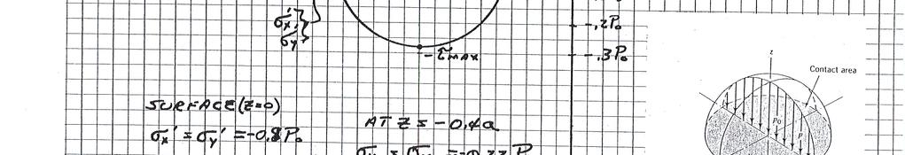
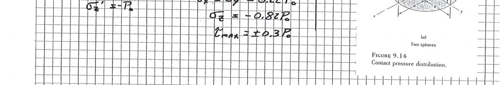
70 Mohr s Circle for Spherical Contact Stress


71 Mohr s Circle for Roller Contact Stress

72 Bearing Failure Below Surface
73 Contact stresses Most rolling members also tend to slide Mating gear teeth Cam and follower Ball and roller bearings Resulting friction forces cause other stresses Tangential normal and shear stresses Superimposed on stresses caused by normal loading
74 Curved beams in bending Must use following assumptions Cross section has axis of symmetry in a plane along the length of the beam Plane cross sections remain plane after bending Modulus of elasticity is same in tension and compression
 i")
75 Curved beams in bending, cont. r n σ σ σ i o Ae A da r My Mci Aer ( r y) i n Mc Aer o o
Tuesday, February 11, Chapter 3. Load and Stress Analysis. Dr. Mohammad Suliman Abuhaiba, PE
 1 Chapter 3 Load and Stress Analysis 2 Chapter Outline Equilibrium & Free-Body Diagrams Shear Force and Bending Moments in Beams Singularity Functions Stress Cartesian Stress Components Mohr s Circle for
Failure from static loading
 Failure from static loading Topics Quiz /1/07 Failures from static loading Reading Chapter 5 Homework HW 3 due /1 HW 4 due /8 What is Failure? Failure any change in a machine part which makes it unable
Chapter 3. Load and Stress Analysis
 Chapter 3 Load and Stress Analysis 2 Shear Force and Bending Moments in Beams Internal shear force V & bending moment M must ensure equilibrium Fig. 3 2 Sign Conventions for Bending and Shear Fig. 3 3
Chapter 3. Load and Stress Analysis. Lecture Slides
 Lecture Slides Chapter 3 Load and Stress Analysis 2015 by McGraw Hill Education. This is proprietary material solely for authorized instructor use. Not authorized for sale or distribution in any manner.
Comb resonator design (2)
") Lecture 6: Comb resonator design () -Intro Intro. to Mechanics of Materials School of Electrical l Engineering i and Computer Science, Seoul National University Nano/Micro Systems & Controls Laboratory
Lecture 6: Comb resonator design () -Intro Intro. to Mechanics of Materials School of Electrical l Engineering i and Computer Science, Seoul National University Nano/Micro Systems & Controls Laboratory
Mechanics of Materials II. Chapter III. A review of the fundamental formulation of stress, strain, and deflection
 Mechanics of Materials II Chapter III A review of the fundamental formulation of stress, strain, and deflection Outline Introduction Assumtions and limitations Axial loading Torsion of circular shafts
Advanced Structural Analysis EGF Section Properties and Bending
 Advanced Structural Analysis EGF316 3. Section Properties and Bending 3.1 Loads in beams When we analyse beams, we need to consider various types of loads acting on them, for example, axial forces, shear
Solution: The moment of inertia for the cross-section is: ANS: ANS: Problem 15.6 The material of the beam in Problem
 Problem 15.4 The beam consists of material with modulus of elasticity E 14x10 6 psi and is subjected to couples M 150, 000 in lb at its ends. (a) What is the resulting radius of curvature of the neutral
2. Rigid bar ABC supports a weight of W = 50 kn. Bar ABC is pinned at A and supported at B by rod (1). What is the axial force in rod (1)?
. What is the axial force in rod (1)?") IDE 110 S08 Test 1 Name: 1. Determine the internal axial forces in segments (1), (2) and (3). (a) N 1 = kn (b) N 2 = kn (c) N 3 = kn 2. Rigid bar ABC supports a weight of W = 50 kn. Bar ABC is pinned at
IDE 110 S08 Test 1 Name: 1. Determine the internal axial forces in segments (1), (2) and (3). (a) N 1 = kn (b) N 2 = kn (c) N 3 = kn 2. Rigid bar ABC supports a weight of W = 50 kn. Bar ABC is pinned at
Chapter 8 Structural Design and Analysis. Strength and stiffness 5 types of load: Tension Compression Shear Bending Torsion
 Chapter 8 Structural Design and Analysis 1 Strength and stiffness 5 types of load: Tension Compression Shear Bending Torsion Normal Stress Stress is a state when a material is loaded. For normal forces
Homework No. 1 MAE/CE 459/559 John A. Gilbert, Ph.D. Fall 2004
 Homework No. 1 MAE/CE 459/559 John A. Gilbert, Ph.D. 1. A beam is loaded as shown. The dimensions of the cross section appear in the insert. the figure. Draw a complete free body diagram showing an equivalent
UNIVERSITY OF SASKATCHEWAN ME MECHANICS OF MATERIALS I FINAL EXAM DECEMBER 13, 2008 Professor A. Dolovich
 UNIVERSITY OF SASKATCHEWAN ME 313.3 MECHANICS OF MATERIALS I FINAL EXAM DECEMBER 13, 2008 Professor A. Dolovich A CLOSED BOOK EXAMINATION TIME: 3 HOURS For Marker s Use Only LAST NAME (printed): FIRST
STRESS. Bar. ! Stress. ! Average Normal Stress in an Axially Loaded. ! Average Shear Stress. ! Allowable Stress. ! Design of Simple Connections
 STRESS! Stress Evisdom! verage Normal Stress in an xially Loaded ar! verage Shear Stress! llowable Stress! Design of Simple onnections 1 Equilibrium of a Deformable ody ody Force w F R x w(s). D s y Support
Samantha Ramirez, MSE. Stress. The intensity of the internal force acting on a specific plane (area) passing through a point. F 2
 passing through a point. F 2") Samantha Ramirez, MSE Stress The intensity of the internal force acting on a specific plane (area) passing through a point. Δ ΔA Δ z Δ 1 2 ΔA Δ x Δ y ΔA is an infinitesimal size area with a uniform force
Samantha Ramirez, MSE Stress The intensity of the internal force acting on a specific plane (area) passing through a point. Δ ΔA Δ z Δ 1 2 ΔA Δ x Δ y ΔA is an infinitesimal size area with a uniform force
Mechanical Properties of Materials
 Mechanical Properties of Materials Strains Material Model Stresses Learning objectives Understand the qualitative and quantitative description of mechanical properties of materials. Learn the logic of
[8] Bending and Shear Loading of Beams
![[8] Bending and Shear Loading of Beams](/thumbs/92/110949676.jpg "[8] Bending and Shear Loading of Beams") [8] Bending and Shear Loading of Beams Page 1 of 28 [8] Bending and Shear Loading of Beams [8.1] Bending of Beams (will not be covered in class) [8.2] Bending Strain and Stress [8.3] Shear in Straight
[8] Bending and Shear Loading of Beams Page 1 of 28 [8] Bending and Shear Loading of Beams [8.1] Bending of Beams (will not be covered in class) [8.2] Bending Strain and Stress [8.3] Shear in Straight
Name (Print) ME Mechanics of Materials Exam # 1 Date: October 5, 2016 Time: 8:00 10:00 PM
 ME Mechanics of Materials Exam # 1 Date: October 5, 2016 Time: 8:00 10:00 PM") Name (Print) (Last) (First) Instructions: ME 323 - Mechanics of Materials Exam # 1 Date: October 5, 2016 Time: 8:00 10:00 PM Circle your lecturer s name and your class meeting time. Gonzalez Krousgrill
Name (Print) (Last) (First) Instructions: ME 323 - Mechanics of Materials Exam # 1 Date: October 5, 2016 Time: 8:00 10:00 PM Circle your lecturer s name and your class meeting time. Gonzalez Krousgrill
Stress and Strain ( , 3.14) MAE 316 Strength of Mechanical Components NC State University Department of Mechanical & Aerospace Engineering
 MAE 316 Strength of Mechanical Components NC State University Department of Mechanical & Aerospace Engineering") (3.8-3.1, 3.14) MAE 316 Strength of Mechanical Components NC State Universit Department of Mechanical & Aerospace Engineering 1 Introduction MAE 316 is a continuation of MAE 314 (solid mechanics) Review
(3.8-3.1, 3.14) MAE 316 Strength of Mechanical Components NC State Universit Department of Mechanical & Aerospace Engineering 1 Introduction MAE 316 is a continuation of MAE 314 (solid mechanics) Review
Comb Resonator Design (2)
") Lecture 6: Comb Resonator Design () -Intro. to Mechanics of Materials Sh School of felectrical ti lengineering i and dcomputer Science, Si Seoul National University Nano/Micro Systems & Controls Laboratory
Lecture 6: Comb Resonator Design () -Intro. to Mechanics of Materials Sh School of felectrical ti lengineering i and dcomputer Science, Si Seoul National University Nano/Micro Systems & Controls Laboratory
Downloaded from Downloaded from / 1
 PURWANCHAL UNIVERSITY III SEMESTER FINAL EXAMINATION-2002 LEVEL : B. E. (Civil) SUBJECT: BEG256CI, Strength of Material Full Marks: 80 TIME: 03:00 hrs Pass marks: 32 Candidates are required to give their
Stress Analysis Lecture 3 ME 276 Spring Dr./ Ahmed Mohamed Nagib Elmekawy
 Stress Analysis Lecture 3 ME 276 Spring 2017-2018 Dr./ Ahmed Mohamed Nagib Elmekawy Axial Stress 2 Beam under the action of two tensile forces 3 Beam under the action of two tensile forces 4 Shear Stress
MECHANICS OF MATERIALS
 STATICS AND MECHANICS OF MATERIALS Ferdinand P. Beer E. Russell Johnston, Jr, John T. DeWolf David E Mazurek \Cawect Mc / iur/» Craw SugomcT Hilt Introduction 1 1.1 What is Mechanics? 2 1.2 Fundamental
NAME: Given Formulae: Law of Cosines: Law of Sines:
 NME: Given Formulae: Law of Cosines: EXM 3 PST PROBLEMS (LESSONS 21 TO 28) 100 points Thursday, November 16, 2017, 7pm to 9:30, Room 200 You are allowed to use a calculator and drawing equipment, only.
D : SOLID MECHANICS. Q. 1 Q. 9 carry one mark each.
 GTE 2016 Q. 1 Q. 9 carry one mark each. D : SOLID MECHNICS Q.1 single degree of freedom vibrating system has mass of 5 kg, stiffness of 500 N/m and damping coefficient of 100 N-s/m. To make the system
Mechanics of Materials Primer
 Mechanics of Materials rimer Notation: A = area (net = with holes, bearing = in contact, etc...) b = total width of material at a horizontal section d = diameter of a hole D = symbol for diameter E = modulus
MECE 3321 MECHANICS OF SOLIDS CHAPTER 1
 MECE 3321 MECHANICS O SOLIDS CHAPTER 1 Samantha Ramirez, MSE WHAT IS MECHANICS O MATERIALS? Rigid Bodies Statics Dynamics Mechanics Deformable Bodies Solids/Mech. Of Materials luids 1 WHAT IS MECHANICS
MAAE 2202 A. Come to the PASS workshop with your mock exam complete. During the workshop you can work with other students to review your work.
 It is most beneficial to you to write this mock final exam UNDER EXAM CONDITIONS. This means: Complete the exam in 3 hours. Work on your own. Keep your textbook closed. Attempt every question. After the
PES Institute of Technology
 PES Institute of Technology Bangalore south campus, Bangalore-5460100 Department of Mechanical Engineering Faculty name : Madhu M Date: 29/06/2012 SEM : 3 rd A SEC Subject : MECHANICS OF MATERIALS Subject
Stress Transformation Equations: u = +135 (Fig. a) s x = 80 MPa s y = 0 t xy = 45 MPa. we obtain, cos u + t xy sin 2u. s x = s x + s y.
 s x = 80 MPa s y = 0 t xy = 45 MPa. we obtain, cos u + t xy sin 2u. s x = s x + s y.") 014 Pearson Education, Inc., Upper Saddle River, NJ. All rights reserved. This material is protected under all copyright laws as they currently 9 7. Determine the normal stress and shear stress acting
014 Pearson Education, Inc., Upper Saddle River, NJ. All rights reserved. This material is protected under all copyright laws as they currently 9 7. Determine the normal stress and shear stress acting
Sub. Code:
 Important Instructions to examiners: ) The answers should be examined by key words and not as word-to-word as given in the model answer scheme. ) The model answer and the answer written by candidate may
ME 323 MIDTERM # 1: SOLUTION FALL SEMESTER Time allowed: 1hour
 Instructions ME 2 MIDTERM # : SOLUTION FALL SEMESTER 20 Time allowed: hour. Begin each problem in the space provided on the examination sheets. If additional space is required, use the yellow paper provided.
Lecture 8. Stress Strain in Multi-dimension
 Lecture 8. Stress Strain in Multi-dimension Module. General Field Equations General Field Equations [] Equilibrium Equations in Elastic bodies xx x y z yx zx f x 0, etc [2] Kinematics xx u x x,etc. [3]
3. BEAMS: STRAIN, STRESS, DEFLECTIONS
 3. BEAMS: STRAIN, STRESS, DEFLECTIONS The beam, or flexural member, is frequently encountered in structures and machines, and its elementary stress analysis constitutes one of the more interesting facets
Symmetric Bending of Beams
 Symmetric Bending of Beams beam is any long structural member on which loads act perpendicular to the longitudinal axis. Learning objectives Understand the theory, its limitations and its applications
ENG2000 Chapter 7 Beams. ENG2000: R.I. Hornsey Beam: 1
 ENG2000 Chapter 7 Beams ENG2000: R.I. Hornsey Beam: 1 Overview In this chapter, we consider the stresses and moments present in loaded beams shear stress and bending moment diagrams We will also look at
Stresses in Curved Beam
 Stresses in Curved Beam Consider a curved beam subjected to bending moment M b as shown in the figure. The distribution of stress in curved flexural member is determined by using the following assumptions:
Mechanical Engineering Ph.D. Preliminary Qualifying Examination Solid Mechanics February 25, 2002
 student personal identification (ID) number on each sheet. Do not write your name on any sheet. #1. A homogeneous, isotropic, linear elastic bar has rectangular cross sectional area A, modulus of elasticity
Consider an elastic spring as shown in the Fig.2.4. When the spring is slowly
 .3 Strain Energy Consider an elastic spring as shown in the Fig..4. When the spring is slowly pulled, it deflects by a small amount u 1. When the load is removed from the spring, it goes back to the original
MEMS Project 2 Assignment. Design of a Shaft to Transmit Torque Between Two Pulleys
 MEMS 029 Project 2 Assignment Design of a Shaft to Transmit Torque Between Two Pulleys Date: February 5, 206 Instructor: Dr. Stephen Ludwick Product Definition Shafts are incredibly important in order
Jeff Brown Hope College, Department of Engineering, 27 Graves Pl., Holland, Michigan, USA UNESCO EOLSS
 MECHANICS OF MATERIALS Jeff Brown Hope College, Department of Engineering, 27 Graves Pl., Holland, Michigan, USA Keywords: Solid mechanics, stress, strain, yield strength Contents 1. Introduction 2. Stress
Chapter Objectives. Copyright 2011 Pearson Education South Asia Pte Ltd
 Chapter Objectives To develop the equations of equilibrium for a rigid body. To introduce the concept of the free-body diagram for a rigid body. To show how to solve rigid-body equilibrium problems using
MECHANICS OF MATERIALS
 GE SI CHAPTER 3 MECHANICS OF MATERIALS Ferdinand P. Beer E. Russell Johnston, Jr. John T. DeWolf David F. Mazurek Torsion Lecture Notes: J. Walt Oler Texas Tech University Torsional Loads on Circular Shafts
SOLUTION (17.3) Known: A simply supported steel shaft is connected to an electric motor with a flexible coupling.
 Known: A simply supported steel shaft is connected to an electric motor with a flexible coupling.") SOLUTION (17.3) Known: A simply supported steel shaft is connected to an electric motor with a flexible coupling. Find: Determine the value of the critical speed of rotation for the shaft. Schematic and
SOLUTION (17.3) Known: A simply supported steel shaft is connected to an electric motor with a flexible coupling. Find: Determine the value of the critical speed of rotation for the shaft. Schematic and
Use Hooke s Law (as it applies in the uniaxial direction),
,") 0.6 STRSS-STRAIN RLATIONSHIP Use the principle of superposition Use Poisson s ratio, v lateral longitudinal Use Hooke s Law (as it applies in the uniaxial direction), x x v y z, y y vx z, z z vx y Copyright
0.6 STRSS-STRAIN RLATIONSHIP Use the principle of superposition Use Poisson s ratio, v lateral longitudinal Use Hooke s Law (as it applies in the uniaxial direction), x x v y z, y y vx z, z z vx y Copyright
five Mechanics of Materials 1 ARCHITECTURAL STRUCTURES: FORM, BEHAVIOR, AND DESIGN DR. ANNE NICHOLS SUMMER 2017 lecture
 ARCHITECTURAL STRUCTURES: FORM, BEHAVIOR, AND DESIGN DR. ANNE NICHOLS SUMMER 2017 lecture five mechanics www.carttalk.com of materials Mechanics of Materials 1 Mechanics of Materials MECHANICS MATERIALS
Equilibrium of a Particle
 ME 108 - Statics Equilibrium of a Particle Chapter 3 Applications For a spool of given weight, what are the forces in cables AB and AC? Applications For a given weight of the lights, what are the forces
Stress Analysis Lecture 4 ME 276 Spring Dr./ Ahmed Mohamed Nagib Elmekawy
 Stress Analysis Lecture 4 ME 76 Spring 017-018 Dr./ Ahmed Mohamed Nagib Elmekawy Shear and Moment Diagrams Beam Sign Convention The positive directions are as follows: The internal shear force causes a
STRENGTH OF MATERIALS-I. Unit-1. Simple stresses and strains
 STRENGTH OF MATERIALS-I Unit-1 Simple stresses and strains 1. What is the Principle of surveying 2. Define Magnetic, True & Arbitrary Meridians. 3. Mention different types of chains 4. Differentiate between
CHAPTER 4: BENDING OF BEAMS
 (74) CHAPTER 4: BENDING OF BEAMS This chapter will be devoted to the analysis of prismatic members subjected to equal and opposite couples M and M' acting in the same longitudinal plane. Such members are
Review Lecture. AE1108-II: Aerospace Mechanics of Materials. Dr. Calvin Rans Dr. Sofia Teixeira De Freitas
 Review Lecture AE1108-II: Aerospace Mechanics of Materials Dr. Calvin Rans Dr. Sofia Teixeira De Freitas Aerospace Structures & Materials Faculty of Aerospace Engineering Analysis of an Engineering System
EMA 3702 Mechanics & Materials Science (Mechanics of Materials) Chapter 3 Torsion
 Chapter 3 Torsion") EMA 3702 Mechanics & Materials Science (Mechanics of Materials) Chapter 3 Torsion Introduction Stress and strain in components subjected to torque T Circular Cross-section shape Material Shaft design Non-circular
EMA 3702 Mechanics & Materials Science (Mechanics of Materials) Chapter 3 Torsion Introduction Stress and strain in components subjected to torque T Circular Cross-section shape Material Shaft design Non-circular
MECHANICS OF MATERIALS. Prepared by Engr. John Paul Timola
 MECHANICS OF MATERIALS Prepared by Engr. John Paul Timola Mechanics of materials branch of mechanics that studies the internal effects of stress and strain in a solid body. stress is associated with the
COURSE TITLE : APPLIED MECHANICS & STRENGTH OF MATERIALS COURSE CODE : 4017 COURSE CATEGORY : A PERIODS/WEEK : 6 PERIODS/ SEMESTER : 108 CREDITS : 5
 COURSE TITLE : APPLIED MECHANICS & STRENGTH OF MATERIALS COURSE CODE : 4017 COURSE CATEGORY : A PERIODS/WEEK : 6 PERIODS/ SEMESTER : 108 CREDITS : 5 TIME SCHEDULE MODULE TOPICS PERIODS 1 Simple stresses
[5] Stress and Strain
![[5] Stress and Strain](/thumbs/95/123344550.jpg "[5] Stress and Strain") [5] Stress and Strain Page 1 of 34 [5] Stress and Strain [5.1] Internal Stress of Solids [5.2] Design of Simple Connections (will not be covered in class) [5.3] Deformation and Strain [5.4] Hooke s Law
[5] Stress and Strain Page 1 of 34 [5] Stress and Strain [5.1] Internal Stress of Solids [5.2] Design of Simple Connections (will not be covered in class) [5.3] Deformation and Strain [5.4] Hooke s Law
3D Elasticity Theory
 3D lasticity Theory Many structural analysis problems are analysed using the theory of elasticity in which Hooke s law is used to enforce proportionality between stress and strain at any deformation level.
PERIYAR CENTENARY POLYTECHNIC COLLEGE PERIYAR NAGAR - VALLAM THANJAVUR. DEPARTMENT OF MECHANICAL ENGINEERING QUESTION BANK
 PERIYAR CENTENARY POLYTECHNIC COLLEGE PERIYAR NAGAR - VALLAM - 613 403 - THANJAVUR. DEPARTMENT OF MECHANICAL ENGINEERING QUESTION BANK Sub : Strength of Materials Year / Sem: II / III Sub Code : MEB 310
GATE SOLUTIONS E N G I N E E R I N G
 GATE SOLUTIONS C I V I L E N G I N E E R I N G From (1987-018) Office : F-16, (Lower Basement), Katwaria Sarai, New Delhi-110016 Phone : 011-65064 Mobile : 81309090, 9711853908 E-mail: info@iesmasterpublications.com,
Mechanics of Materials
 Mechanics of Materials 2. Introduction Dr. Rami Zakaria References: 1. Engineering Mechanics: Statics, R.C. Hibbeler, 12 th ed, Pearson 2. Mechanics of Materials: R.C. Hibbeler, 9 th ed, Pearson 3. Mechanics
Aluminum shell. Brass core. 40 in
 PROBLEM #1 (22 points) A solid brass core is connected to a hollow rod made of aluminum. Both are attached at each end to a rigid plate as shown in Fig. 1. The moduli of aluminum and brass are EA=11,000
: APPLIED MECHANICS & STRENGTH OF MATERIALS COURSE CODE : 4021 COURSE CATEGORY : A PERIODS/ WEEK : 5 PERIODS/ SEMESTER : 75 CREDIT : 5 TIME SCHEDULE
 COURSE TITLE : APPLIED MECHANICS & STRENGTH OF MATERIALS COURSE CODE : 4021 COURSE CATEGORY : A PERIODS/ WEEK : 5 PERIODS/ SEMESTER : 75 CREDIT : 5 TIME SCHEDULE MODULE TOPIC PERIODS 1 Simple stresses
ME311 Machine Design
 ME311 Machine Design Lecture : Materials; Stress & Strain; Power Transmission W Dornfeld 13Sep018 airfield University School of Engineering Stress-Strain Curve for Ductile Material Ultimate Tensile racture
CE6306 STRENGTH OF MATERIALS TWO MARK QUESTIONS WITH ANSWERS ACADEMIC YEAR
 CE6306 STRENGTH OF MATERIALS TWO MARK QUESTIONS WITH ANSWERS ACADEMIC YEAR 2014-2015 UNIT - 1 STRESS, STRAIN AND DEFORMATION OF SOLIDS PART- A 1. Define tensile stress and tensile strain. The stress induced
MECHANICS OF MATERIALS
 CHATR Stress MCHANICS OF MATRIALS and Strain Axial Loading Stress & Strain: Axial Loading Suitability of a structure or machine may depend on the deformations in the structure as well as the stresses induced
Chapter 12. Static Equilibrium and Elasticity
 Chapter 12 Static Equilibrium and Elasticity Static Equilibrium Equilibrium implies that the object moves with both constant velocity and constant angular velocity relative to an observer in an inertial
6. Bending CHAPTER OBJECTIVES
 CHAPTER OBJECTIVES Determine stress in members caused by bending Discuss how to establish shear and moment diagrams for a beam or shaft Determine largest shear and moment in a member, and specify where
MECHANICS OF MATERIALS
 2009 The McGraw-Hill Companies, Inc. All rights reserved. Fifth SI Edition CHAPTER 3 MECHANICS OF MATERIALS Ferdinand P. Beer E. Russell Johnston, Jr. John T. DeWolf David F. Mazurek Torsion Lecture Notes:
3 2 6 Solve the initial value problem u ( t) 3. a- If A has eigenvalues λ =, λ = 1 and corresponding eigenvectors 1
 3. a- If A has eigenvalues λ =, λ = 1 and corresponding eigenvectors 1") Math Problem a- If A has eigenvalues λ =, λ = 1 and corresponding eigenvectors 1 3 6 Solve the initial value problem u ( t) = Au( t) with u (0) =. 3 1 u 1 =, u 1 3 = b- True or false and why 1. if A is
Math Problem a- If A has eigenvalues λ =, λ = 1 and corresponding eigenvectors 1 3 6 Solve the initial value problem u ( t) = Au( t) with u (0) =. 3 1 u 1 =, u 1 3 = b- True or false and why 1. if A is
The case where there is no net effect of the forces acting on a rigid body
 The case where there is no net effect of the forces acting on a rigid body Outline: Introduction and Definition of Equilibrium Equilibrium in Two-Dimensions Special cases Equilibrium in Three-Dimensions
PDDC 1 st Semester Civil Engineering Department Assignments of Mechanics of Solids [ ] Introduction, Fundamentals of Statics
![PDDC 1 st Semester Civil Engineering Department Assignments of Mechanics of Solids [ ] Introduction, Fundamentals of Statics](/thumbs/92/109382806.jpg "PDDC 1 st Semester Civil Engineering Department Assignments of Mechanics of Solids [ ] Introduction, Fundamentals of Statics") Page1 PDDC 1 st Semester Civil Engineering Department Assignments of Mechanics of Solids [2910601] Introduction, Fundamentals of Statics 1. Differentiate between Scalar and Vector quantity. Write S.I.
Page1 PDDC 1 st Semester Civil Engineering Department Assignments of Mechanics of Solids [2910601] Introduction, Fundamentals of Statics 1. Differentiate between Scalar and Vector quantity. Write S.I.
MECE 3321: Mechanics of Solids Chapter 6
 MECE 3321: Mechanics of Solids Chapter 6 Samantha Ramirez Beams Beams are long straight members that carry loads perpendicular to their longitudinal axis Beams are classified by the way they are supported
When a rigid body is in equilibrium, both the resultant force and the resultant couple must be zero.
 When a rigid body is in equilibrium, both the resultant force and the resultant couple must be zero. 0 0 0 0 k M j M i M M k R j R i R F R z y x z y x Forces and moments acting on a rigid body could be
PURE BENDING. If a simply supported beam carries two point loads of 10 kn as shown in the following figure, pure bending occurs at segment BC.
 BENDING STRESS The effect of a bending moment applied to a cross-section of a beam is to induce a state of stress across that section. These stresses are known as bending stresses and they act normally
D : SOLID MECHANICS. Q. 1 Q. 9 carry one mark each. Q.1 Find the force (in kn) in the member BH of the truss shown.
 in the member BH of the truss shown.") D : SOLID MECHANICS Q. 1 Q. 9 carry one mark each. Q.1 Find the force (in kn) in the member BH of the truss shown. Q.2 Consider the forces of magnitude F acting on the sides of the regular hexagon having
D : SOLID MECHANICS Q. 1 Q. 9 carry one mark each. Q.1 Find the force (in kn) in the member BH of the truss shown. Q.2 Consider the forces of magnitude F acting on the sides of the regular hexagon having
Structural Analysis I Chapter 4 - Torsion TORSION
 ORSION orsional stress results from the action of torsional or twisting moments acting about the longitudinal axis of a shaft. he effect of the application of a torsional moment, combined with appropriate
3.1 CONDITIONS FOR RIGID-BODY EQUILIBRIUM
 3.1 CONDITIONS FOR RIGID-BODY EQUILIBRIUM Consider rigid body fixed in the x, y and z reference and is either at rest or moves with reference at constant velocity Two types of forces that act on it, the
(48) CHAPTER 3: TORSION
 CHAPTER 3: TORSION") (48) CHAPTER 3: TORSION Introduction: In this chapter structural members and machine parts that are in torsion will be considered. More specifically, you will analyze the stresses and strains in members
(48) CHAPTER 3: TORSION Introduction: In this chapter structural members and machine parts that are in torsion will be considered. More specifically, you will analyze the stresses and strains in members
Announcements. Equilibrium of a Rigid Body
 Announcements Equilibrium of a Rigid Body Today s Objectives Identify support reactions Draw a free body diagram Class Activities Applications Support reactions Free body diagrams Examples Engr221 Chapter
Chapter 5: Torsion. 1. Torsional Deformation of a Circular Shaft 2. The Torsion Formula 3. Power Transmission 4. Angle of Twist CHAPTER OBJECTIVES
 CHAPTER OBJECTIVES Chapter 5: Torsion Discuss effects of applying torsional loading to a long straight member (shaft or tube) Determine stress distribution within the member under torsional load Determine
two structural analysis (statics & mechanics) APPLIED ACHITECTURAL STRUCTURES: DR. ANNE NICHOLS SPRING 2017 lecture STRUCTURAL ANALYSIS AND SYSTEMS
 APPLIED ACHITECTURAL STRUCTURES: DR. ANNE NICHOLS SPRING 2017 lecture STRUCTURAL ANALYSIS AND SYSTEMS") APPLIED ACHITECTURAL STRUCTURES: STRUCTURAL ANALYSIS AND SYSTEMS DR. ANNE NICHOLS SPRING 2017 lecture two structural analysis (statics & mechanics) Analysis 1 Structural Requirements strength serviceability
APPLIED ACHITECTURAL STRUCTURES: STRUCTURAL ANALYSIS AND SYSTEMS DR. ANNE NICHOLS SPRING 2017 lecture two structural analysis (statics & mechanics) Analysis 1 Structural Requirements strength serviceability
Constitutive Equations (Linear Elasticity)
") Constitutive quations (Linear lasticity) quations that characterize the physical properties of the material of a system are called constitutive equations. It is possible to find the applied stresses knowing
Constitutive quations (Linear lasticity) quations that characterize the physical properties of the material of a system are called constitutive equations. It is possible to find the applied stresses knowing
Torsion of shafts with circular symmetry
 orsion of shafts with circular symmetry Introduction Consider a uniform bar which is subject to a torque, eg through the action of two forces F separated by distance d, hence Fd orsion is the resultant
ME Final Exam. PROBLEM NO. 4 Part A (2 points max.) M (x) y. z (neutral axis) beam cross-sec+on. 20 kip ft. 0.2 ft. 10 ft. 0.1 ft.
 M (x) y. z (neutral axis) beam cross-sec+on. 20 kip ft. 0.2 ft. 10 ft. 0.1 ft.") ME 323 - Final Exam Name December 15, 2015 Instructor (circle) PROEM NO. 4 Part A (2 points max.) Krousgrill 11:30AM-12:20PM Ghosh 2:30-3:20PM Gonzalez 12:30-1:20PM Zhao 4:30-5:20PM M (x) y 20 kip ft 0.2
ME 323 - Final Exam Name December 15, 2015 Instructor (circle) PROEM NO. 4 Part A (2 points max.) Krousgrill 11:30AM-12:20PM Ghosh 2:30-3:20PM Gonzalez 12:30-1:20PM Zhao 4:30-5:20PM M (x) y 20 kip ft 0.2
SEMM Mechanics PhD Preliminary Exam Spring Consider a two-dimensional rigid motion, whose displacement field is given by
 SEMM Mechanics PhD Preliminary Exam Spring 2014 1. Consider a two-dimensional rigid motion, whose displacement field is given by u(x) = [cos(β)x 1 + sin(β)x 2 X 1 ]e 1 + [ sin(β)x 1 + cos(β)x 2 X 2 ]e
Sample Questions for the ME328 Machine Design Final Examination Closed notes, closed book, no calculator.
 Sample Questions for the ME328 Machine Design Final Examination Closed notes, closed book, no calculator. The following is from the first page of the examination. I recommend you read it before the exam.
FINAL EXAMINATION. (CE130-2 Mechanics of Materials)
") UNIVERSITY OF CLIFORNI, ERKELEY FLL SEMESTER 001 FINL EXMINTION (CE130- Mechanics of Materials) Problem 1: (15 points) pinned -bar structure is shown in Figure 1. There is an external force, W = 5000N,
UNIVERSITY OF CLIFORNI, ERKELEY FLL SEMESTER 001 FINL EXMINTION (CE130- Mechanics of Materials) Problem 1: (15 points) pinned -bar structure is shown in Figure 1. There is an external force, W = 5000N,
INTRODUCTION TO STRAIN
 SIMPLE STRAIN INTRODUCTION TO STRAIN In general terms, Strain is a geometric quantity that measures the deformation of a body. There are two types of strain: normal strain: characterizes dimensional changes,
STRESS STRAIN AND DEFORMATION OF SOLIDS, STATES OF STRESS
 1 UNIT I STRESS STRAIN AND DEFORMATION OF SOLIDS, STATES OF STRESS 1. Define: Stress When an external force acts on a body, it undergoes deformation. At the same time the body resists deformation. The
9 MECHANICAL PROPERTIES OF SOLIDS
 9 MECHANICAL PROPERTIES OF SOLIDS Deforming force Deforming force is the force which changes the shape or size of a body. Restoring force Restoring force is the internal force developed inside the body
Chapter 5 CENTRIC TENSION OR COMPRESSION ( AXIAL LOADING )
") Chapter 5 CENTRIC TENSION OR COMPRESSION ( AXIAL LOADING ) 5.1 DEFINITION A construction member is subjected to centric (axial) tension or compression if in any cross section the single distinct stress
Chapter 5 CENTRIC TENSION OR COMPRESSION ( AXIAL LOADING ) 5.1 DEFINITION A construction member is subjected to centric (axial) tension or compression if in any cross section the single distinct stress
QUESTION BANK SEMESTER: III SUBJECT NAME: MECHANICS OF SOLIDS
 QUESTION BANK SEMESTER: III SUBJECT NAME: MECHANICS OF SOLIDS UNIT 1- STRESS AND STRAIN PART A (2 Marks) 1. Define longitudinal strain and lateral strain. 2. State Hooke s law. 3. Define modular ratio,
7.4 The Elementary Beam Theory
 7.4 The Elementary Beam Theory In this section, problems involving long and slender beams are addressed. s with pressure vessels, the geometry of the beam, and the specific type of loading which will be
Module 2 Stresses in machine elements. Version 2 ME, IIT Kharagpur
 Module Stresses in machine elements Lesson Compound stresses in machine parts Instructional Objectives t the end of this lesson, the student should be able to understand Elements of force system at a beam
VYSOKÁ ŠKOLA BÁŇSKÁ TECHNICKÁ UNIVERZITA OSTRAVA
 VYSOKÁ ŠKOLA BÁŇSKÁ TECHNICKÁ UNIVERZITA OSTRAVA FAKULTA METALURGIE A MATERIÁLOVÉHO INŽENÝRSTVÍ APPLIED MECHANICS Study Support Leo Václavek Ostrava 2015 Title:Applied Mechanics Code: Author: doc. Ing.
Pressure Vessels Stresses Under Combined Loads Yield Criteria for Ductile Materials and Fracture Criteria for Brittle Materials
 Pressure Vessels Stresses Under Combined Loads Yield Criteria for Ductile Materials and Fracture Criteria for Brittle Materials Pressure Vessels: In the previous lectures we have discussed elements subjected
Name: Fall 2014 CLOSED BOOK
 Name: Fall 2014 1. Rod AB with weight W = 40 lb is pinned at A to a vertical axle which rotates with constant angular velocity ω =15 rad/s. The rod position is maintained by a horizontal wire BC. Determine
IDE 110 Mechanics of Materials Spring 2006 Final Examination FOR GRADING ONLY
 Spring 2006 Final Examination STUDENT S NAME (please print) STUDENT S SIGNATURE STUDENT NUMBER IDE 110 CLASS SECTION INSTRUCTOR S NAME Do not turn this page until instructed to start. Write your name on
SN QUESTION YEAR MARK 1. State and prove the relationship between shearing stress and rate of change of bending moment at a section in a loaded beam.
 ALPHA COLLEGE OF ENGINEERING AND TECHNOLOGY DEPARTMENT OF MECHANICAL ENGINEERING MECHANICS OF SOLIDS (21000) ASSIGNMENT 1 SIMPLE STRESSES AND STRAINS SN QUESTION YEAR MARK 1 State and prove the relationship
R13. II B. Tech I Semester Regular Examinations, Jan MECHANICS OF SOLIDS (Com. to ME, AME, AE, MTE) PART-A
 PART-A") SET - 1 II B. Tech I Semester Regular Examinations, Jan - 2015 MECHANICS OF SOLIDS (Com. to ME, AME, AE, MTE) Time: 3 hours Max. Marks: 70 Note: 1. Question Paper consists of two parts (Part-A and Part-B)
SET - 1 II B. Tech I Semester Regular Examinations, Jan - 2015 MECHANICS OF SOLIDS (Com. to ME, AME, AE, MTE) Time: 3 hours Max. Marks: 70 Note: 1. Question Paper consists of two parts (Part-A and Part-B)
JUT!SI I I I TO BE RETURNED AT THE END OF EXAMINATION. THIS PAPER MUST NOT BE REMOVED FROM THE EXAM CENTRE. SURNAME: FIRST NAME: STUDENT NUMBER:
 JUT!SI I I I TO BE RETURNED AT THE END OF EXAMINATION. THIS PAPER MUST NOT BE REMOVED FROM THE EXAM CENTRE. SURNAME: FIRST NAME: STUDENT NUMBER: COURSE: Tutor's name: Tutorial class day & time: SPRING
QUESTION BANK DEPARTMENT: CIVIL SEMESTER: III SUBJECT CODE: CE2201 SUBJECT NAME: MECHANICS OF SOLIDS UNIT 1- STRESS AND STRAIN PART A
 DEPARTMENT: CIVIL SUBJECT CODE: CE2201 QUESTION BANK SEMESTER: III SUBJECT NAME: MECHANICS OF SOLIDS UNIT 1- STRESS AND STRAIN PART A (2 Marks) 1. Define longitudinal strain and lateral strain. 2. State