MS/Standard how to order
|
|
|
- Dorothy Ward
- 6 years ago
- Views:
Transcription
1
2 /tandard how to order I and I-5015 ype (older ontacts) W () onnector ype designates ilitary tandard * designates service class and with proprietary special * designates service class with proprietary special * designates service class and with proprietary special 2. onnector tyle 100 wall mounting receptacle 101 cable connecting plug 102 box mounting receptacle 10 straight plug plug. ervice lass solid shell for general, non-environmental applications solid shell for pressurized applications environmental resisting environmental resisting with strain relief ( part number only) lightweight environmental resisting., 5.hell size and insert arrangement - see tables, pages ontact ypes designates pin contact designates socket contact 7. Insert otation W, X,, or designate that insert is rotated in its shell from normal position. o letter required for normal (no rotation) position. 8. () strain relief for non-military connectors (or use class) * or insert arrangements over 50 and shell size 0 and above. xceptions: -52, 0-1, 0-9 and 0-5 are approved. onsult mphenol, idney, for availability of alternate finishes, including black and olive drab zinc alloys. roprietary (rimp ontacts) onnector ype 75 connector utilizing silver plated contacts 80 less contacts 85 contacts utilizing 50 micro-inches gold over silver plating 2. ervice lass 8 service class, general duty 7 service class, environmental resisting 190 service class, lightweight environmental resisting. onnector tyle 0 wall mounting receptacle 1 cable connecting plug 2 box mounting receptacle straight plug 8 90 plug. hell ize esignator hell ize hell esignator hell ize hell esignator Insert rrangements ee page ontact ype/lternate Insert otation designates pin, designates socket for normal positioning of inserts. When an alternate position of the connector insert is required to prevent cross-mating, a different letter (other than or ) is used. ee page 25 for description of alternate positions, then convert to mphenol proprietary coding by the following charts: etter in ontacts mphenol etter etter ocket ontacts mphenol etter W W X I X 70
 at sea level ed couplings ingle key/keyway shell polarization ost effective O OIO ive shell styles ineteen shell sizes 05 from 1 to 10 circuits older or crimp contacts, sizes 1-0 accepting")
 available connectors meet the latest")

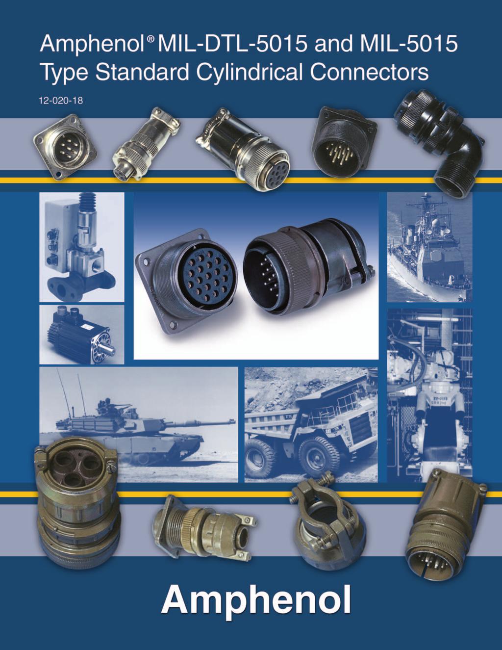
3 mphenol I and I-5015 ype tandard ylindrical onnectors -, - -/ - I II edium to heavy weight cylindrical urable, field-proven design nvironmental resistant esilient inserts Operating voltage to 000 () at sea level ed couplings ingle key/keyway shell polarization ost effective O OIO ive shell styles ineteen shell sizes 05 from 1 to 10 circuits older or crimp contacts, sizes 1-0 accepting 22-0 W. oaxial and thermocouple contact options ive class designations lternate insert positioning ermetic configurations available inc alloy plating (cadmium-free) available connectors meet the latest performance requirements of I hese connectors represent well-proven electrical capability at an acceptable cost for most equipment where durability is important. I features threaded couplings and single key/keyway polarization, representing maximum simplicity in design. pplications include military ground support equipment, ordnance and shipboard installations. mphenol Industrial Operations manufactures five classes of connectors to meet different requirements. lass designations and brief descriptions are listed below. olid hell for general, non-environmental applications. ressurized for use on pressurized bulkheads or pressure barriers; limits air leakage regardless of type and class of plug mated with them. / nvironmental esisting with train elief designed for applications where the connector will be exposed to moisture, vibration, and rapid changes in pressure and temperature. ightweight nvironmental esisting shorter in length and lighter in weight than the and classes, the - offers a high degree of reliability under adverse conditions: recommended for new design applications.


4 /tandard - and - wall mounting receptacle cable connecting plug box mounting receptacle - and - - and - class connectors perform many of the vital functions in powering, testing and ground support systems. lass applications include communications equipment, computers and shipboard installations where mechanical forces and physical parameters are not subject to extreme or rapid environmental changes. lass connectors are most frequently used on pressurized bulkheads or pressure barriers at elevated altitudes or maritime applications. ir leakage is limited to one cubic inch per hour at a pressure differential of 0 lbs. per square inch. hells: hell components are fabricated from high grade aluminum alloy. lectrically conductive cadmium plate finish with an olive drab chromate after-treat offers corrosion resistance. ontacts: ontacts are available in both solder and crimp versions. ins and sockets are machined from copper alloy with a silver plated finish. ize 1 and 12 socket contacts incorporate a closed entry design. efer to pages 9, 7 and 8 for additional contact information. Inserts: Inserts are resilient neoprene, offering high dielectric strength, high arc resistance and resistance to vibration. roprietary design permits pressurization of either pin or socket insert. straight plug 90 degree plug
5 /tandard 100 or wall mounting receptacle oles o complete order number, see how to order pg. 70. or solder well data, see page 7. hell ize lass 2 in ull ± ±.005 ±.01 ia lass * * * * * * * * *** ** 8*** ** * Increase dimension by.12 for size 0 contact only. ** Increase dimension by.02 for size 0 contact only. *** vailable in proprietary version only ±
6 /tandard 101 cable connecting plug o complete order number, see how to order pg. 70. or solder well data, see page 7. hell ize lass 2 in. ull ±.00 ia. ax. lass 2 ± * * * * * * * * *** ** * Increase dimension by.12 for size 0 contact only. ** Increase dimension by.02 for size 0 contact only. *** vailable in proprietary version only.
7 /tandard 102 or box mounting receptacle oles o complete order number, see how to order pg. 70. or solder well data, see page 7. hell ize lass 2 in ull ia ±.005 ±.01 ia * * * * * * * *** ** 8*** ** * Increase dimension by.12 for size 0 contact only. ** Increase dimension by.02 for size 0 contact only. *** vailable in proprietary version only ±.020 7
8 /tandard 10 straight plug Q o complete order number, see how to order pg. 70. or solder well data, see page 7. ll lockwire holes are.05 dia. min. hell ize lass 2 ±.005 ±.00 Q ia. ax. lass 2 ± * * * * * * * * *** ** 8*** ** * Increase dimension by.12 for size 0 contact only. ** Increase dimension by.02 for size 0 contact only. *** vailable in proprietary version only
9 /tandard degree plug Q W o complete order number, see how to order pg. 70. or solder well data, see page 7. ll lockwire holes are.05 dia. min. hell ize lass 2 ±.005 ax. Q ia. ax. ax. lass 2 W ± * * * * * * * * * Increase dimension by.12 for size 0 contact only. 9
.")


10 /tandard -/ wall mounting receptacle cable connecting plug box mounting receptacle - & lass connectors satisfy all the performance requirements of I lass, environmental is also produced, but is no longer listed on the qualified products listing (Q). hese connectors are recommended for conditions where vibration, moisture, pressure and/or temperature are extreme. train relief is supplied on most shell sizes. hells: hell components are fabricated from high grade aluminum alloy. he standard hardware plating is electrically conductive cadmium plated finish with an olive drab chromate after-treatment for corrosion resistance. onsult mphenol, idney, for other plating options. ontacts: ontacts are silver plated copper alloy for maximum corrosion resistance, maximum current carrying capacity and low millivolt drop. ize 1 and 12 socket contacts incorporate a closed entry design. rimp and solder versions are available. efer to pages 9, 7 and 8 for additional contact information. Inserts: esilient neoprene inserts provide an outstanding moisture barrier, high dielectric strength, and resistance to vibration. ither pin or socket insert can be pressurized. train elief lamp: train relief clamps minimize tension at the solder well connection and provide a positive mechanical moisture seal. omplete field serviceability is possible with the strain relief clamp. straight plug 90 degree plug 10
11 /tandard 100/ wall mounting receptacle XX oles o complete order number, see how to order pg. 70. or solder well data, see page 7. hell ize lass 2 in. ull ax ax. ±.005 ±.010 ia * ax. XX in. able learance * Increase dimension by.12 for size 0 contact only. 11
12 /tandard 101/ cable connecting plug XX o complete order number, see how to order pg. 70. or solder well data, see page 7. hell ize lass 2 in. ull ax. ax. * ax. XX in. able learance * Increase dimension by.12 for size 0 contact only. 12
13 /tandard 102 box mounting receptacle oles o complete order number, see how to order pg. 70. or solder well data, see page 7. hell ize lass 2 in. ull ia ±.005 ±.01 ia * * * * * * * * * Increase dimension by.12 for size 0 contact only. 1
14 /tandard 10/ straight plug Q XX o complete order number, see how to order pg. 70. or solder well data, see page 7. ll lockwire holes are.05 dia. min. hell ize lass 2 ±.005 ax. ax. Q ax. * ±.05 XX in. able learance * Increase dimension by.12 for size 0 contact only. 1
15 /tandard degree plug Q o complete order number, see how to order pg. 70. or solder well data, see page 7. ll lockwire holes are.05 dia. min. hell ize lass 2 ±.005 ax. ax. Q ia. ax. ax. lass 2 ± * * * * * * * * * Increase dimension by.12 for size 0 contact only. 15


16 /tandard - wall mounting receptacle cable connecting plug box mounting receptacle - pecification requirements for greater reliability in a shorter, lighter weight environmental resistant connector led to the design of the -. lass connectors satisfy all the performance requirements of I his low profile assembly was attained by moving the axial compression nut and grommet assembly forward and flush with the rear of the insert. he neoprene grommet, with its low coefficient of friction, assures easier threading of wire bundles and quicker assembly and serviceability of the unit. olded webs in each wire hole insure a moisture barrier around each wire. he addition of an O ring at the main joint of all 10 plugs provide a main joint seal supplementary to the interfacial seal, thus insuring a higher degree of reliability when connector halves from different sources are employed. - types are recommended for new design applications. hells: hell components are fabricated from high grade aluminum alloy. ll components have the standard electrically conductive cadmium plated finish with an olive drab chromate after-treatment for corrosion resistance. onsult mphenol, idney, for other plating options. ontacts: ontacts are machined from copper alloy for maximum corrosion resistance, maximum current carrying capacity and low millivolt drop. oth crimp and solder versions are available. efer to pages 9, 7 and 8 for additional contact information. Inserts: esilient neoprene inserts provide an outstanding moisture barrier, maximum vibration resistance and high dielectric strength. ither pin or socket insert can be pressurized. straight plug 1
17 /tandard 100 wall mounting receptacle oles o complete order number, see how to order pg. 70. or solder well data, see page 7. ll lockwire holes are.05 dia. min. hell ize lass 2 in. ull ia. ax ax ia. ax. ±.005 ±.01 lass * * * * * * * * * Increase dimension by.12 for size 0 contact only. ia
18 /tandard 101 cable connecting plug o complete order number, see how to order pg. 70. or solder well data, see page 7. ll lockwire holes are.05 dia. min. hell ize lass 2 in. ull ia. ax. ia. ax. ax. lass 2 ± * * * * * * * * * Increase dimension by.12 for size 0 contact only. 18
19 /tandard 102 box mounting receptacle oles o complete order number, see how to order pg. 70. or solder well data, see page 7. hell ize lass 2 in. ull ia ±.005 ±.01 ia * * * * * * * * * Increase dimension by.12 for size 0 contact only. 19
20 /tandard 10 straight plug Q o complete order number, see how to order pg. 70. or solder well data, see page 7. ll lockwire holes are.05 dia. min. hell ize lass 2 ia. ax. ±.005 ax. ia. ax. Q ia. ax. lass 2 ± * * * * * * * * * Increase dimension by.12 for size 0 contact only. 20
21 21 /tandard contact and insert arrangements
22 /tandard insert arrangements Insert ervice otal ontact ize rrangement ating ontacts Inst Inst Inst Inst /Inst Inst Inst /Inst Insert rrangement ervice ating otal ontacts ontact ize / Inst / Inst Inst Inst / / / / / / / arrangement available only with pin contacts in receptacle and socket contacts in plug
23 /tandard insert arrangements, cont. Insert ervice otal ontact ize rrangement ating ontacts / / / / Inst / / // / // ///Inst // Insert ervice otal ontact ize rrangement ating ontacts / / Inst./ /// / / / /
24 /tandard special insert arrangements Insert rrange ment otal ontacts ontact ize ervice oax** ating /0 2/ * * 20-5* / / 8 8* * i olt * Inst * * Inst Inst oax * * Inst Inst./ * oax oax oax Inst oax * rimp contacts accommodate wire the same size as the contact as well as wire of the next smaller, even size. rrangements identified with an asterisk (*) are exceptions. ee insert arrangement drawings on pages 8-8 for application wire size. ** oaxial cable data can be found on insert arrangement drawings, pages 8-8. or further information on coaxial contacts and cable see catalog Insert rrange ervice ontact ize oax** otal on- ment ating tacts /0 2/ * * * 0 - oax -5 oax oax * * -8 oax / 5 5* * 0- oax oax * * Inst
25 /tandard insert alternate positioning o avoid cross-plugging problems in applications requiring the use of more than one connector of the same size and arrangement, alternate rotations are available as indicated in the accompanying charts. s shown in the diagram below, the front face of the pin insert is rotated within the shell in a clockwise direction from the normal shell key. he socket insert would be rotated counter-clockwise the same number of degrees in respect to the normal shell key. osition W osition X osition osition iew looking into front face of pin insert or rear of socket insert. he following insert arrangements have the same alternate insert rotations for W, X, and, which are: egrees W X Insert egrees rrangement W X Insert rrangement egrees W X Insert rrangement egrees W X
26 /tandard front face of pin insert or rear face of socket insert illustrated ront of ocket Insert ront of ocket Insert Insert rrangement ervice ating umber of ontacts ontact ize Insert rrangement ervice ating Inst. Inst. Inst. umber of ontacts ontact ize otation of otation of 1-7 Insert rrangement ervice ating Inst. umber of ontacts ontact ize Insert rrangement ervice ating umber of ontacts ontact ize O
27 /tandard front face of pin insert or rear face of socket insert illustrated I Insert rrangement ervice ating,,, = ; al. = Inst. umber of ontacts 2 1 2* 10 2 ontact ize Insert rrangement ervice ating Inst. umber of ontacts ontact ize Insert rrangement ervice ating umber of ontacts ** ontact ize I otation of otation of 18-1 Insert rrangement ervice ating Inst.,,, = ; al. = Inst. umber of ontacts ontact ize * = Iron; = onstantan **, = Iron;, = onstantan 27 O
28 28 front face of pin insert or rear face of socket insert illustrated /tandard Insert rrangement ervice ating umber of ontacts ontact ize Insert rrangement ervice ating,,, = ;,,, = Inst. = ; al. = Inst. umber of ontacts ontact ize Insert rrangement ervice ating umber of ontacts ontact ize O otation of otation of I I
29 29 front face of pin insert or rear face of socket insert illustrated /tandard Insert rrangement ervice ating Inst. umber of ontacts ontact ize Insert rrangement ervice ating Inst. umber of ontacts ontact ize Insert rrangement ervice ating umber of ontacts ontact ize O otation of otation of I I
30 0 front face of pin insert or rear face of socket insert illustrated /tandard Insert rrangement ervice ating = ;,,, = umber of ontacts ontact ize Insert rrangement ervice ating = ;,,,, = = ; al. =,,,, = ;,, = umber of ontacts ontact ize Insert rrangement ervice ating = ; al. = umber of ontacts ontact ize O
31 1 front face of pin insert or rear face of socket insert illustrated /tandard Insert rrangement ervice ating,, = ;,, = = ; al. =,,, = ;,, = = ; al. = * umber of ontacts ontact ize Insert rrangement ervice ating,, = ; al. = umber of ontacts ontact ize Insert rrangement ervice ating umber of ontacts ontact ize O I O I *,,, = Iron,,, = onstantan
32 2 front face of pin insert or rear face of socket insert illustrated /tandard Insert rrangement ervice ating,,, = ;,,, = umber of ontacts ontact ize Insert rrangement ervice ating Inst.,, = ; al. = umber of ontacts ontact ize Insert rrangement ervice ating,, = ; al. = umber of ontacts ontact ize O Q W X
33 front face of pin insert or rear face of socket insert illustrated /tandard Insert rrangement ervice ating, = ; = ; al. = = ; al. = umber of ontacts ontact ize Insert rrangement ervice ating umber of ontacts ontact ize Insert rrangement ervice ating = ;,, = ; to = = ;,,,, = ;, = ; al. = Inst., = ;, = ; al. = umber of ontacts ontact ize O otation of W X a b d I W X W X a b d W X a b c d e f g h j k m l Q
34 front face of pin insert or rear face of socket insert illustrated /tandard Insert rrangement ervice ating = ;,,, = umber of ontacts ontact ize Insert rrangement ervice ating,,, = ; al. = umber of ontacts ontact ize Insert rrangement ervice ating,, h, j = Inst.; al. = umber of ontacts ontact ize O W X a b c d e f g h j k m n p r s O O W I X I O W X a b c d e f g h j k I O W X a b c d e I
35 /tandard front face of pin insert or rear face of socket insert illustrated X W O Insert rrangement ervice ating, = ; = ;, = ;, =,,,, = ; al. = umber of ontacts ontact ize I O W X O W X a c d e b f g h j k m r n p q t u v s x w y z I O W 100 otation of 2- Insert rrangement ervice ating umber of ontacts ontact ize Insert rrangement ervice ating = ;, = umber of ontacts 2 ontact ize O
36 /tandard front face of pin insert or rear face of socket insert illustrated I O W X a b c e d f g h k m j t n u p v r s w x y z I O W a X b c d e f g k h j n p m r s u t v w x z y d e f a W b c X I O Insert rrangement ervice ating umber of ontacts ontact ize O Q W X a b c d e f g h j k m n p q r s t u v w x y z O Q W X a b c d e f g h j k m n p q r s t u v w x y z O Q W X a b c d e f g h j k q m n p r s t u v w x y z 100 otation of otation of -10 Insert rrangement ervice ating umber of ontacts ontact ize Q I Q Q d c k j b h a e m f W g X Insert rrangement ervice ating,, Q = ; al. = = ; al. = umber of ontacts ontact ize O
37 /tandard front face of pin insert or rear face of socket insert illustrated 100 I O W X a b c d e f g h j t k n p m u w v r s 110 I O W X a b c e d f g m h j t k n u v p w r s 100 a d e f W b c X I O x z y x z y 100 otation of otation of otation of -9 Insert rrangement ervice ating umber of ontacts ontact ize W X a b c d e h j f g k m W X a b c d f g h i j k m n p q r s t u v w x y z I O W X a b c d e Insert rrangement ervice ating umber of ontacts ontact ize I O Q W X a b c d g h i e f l m j o k n p q r s t u W X a b c d f g q h i j k m n p r s t u v w x y z W X Insert rrangement ervice ating umber of ontacts ontact ize O
38 8 pecial equirements for more complex circuits prompted mphenol to provide inserts not covered by the drawings. Illustrated here and on the following pages are insert layouts which have from one contact (high tension) to the 10 contact insert in shell size. any of these special inserts are also available in alternate keyway arrangements. lease contact mphenol, idney, for additional information on special circuit application requirements. front face of pin insert or rear face of socket insert illustrated Insert rrangement ervice ating umber of ontacts 7 19 * 7* 5 5 ontact ize for #1 or 1 wire 12 1 Insert rrangement ervice ating = ; al. = = ; al. = umber of ontacts * 1 5 7* 1* 8 8* 8 5 ontact ize 8 for #10 or 12 wire 1 12 for #10 wire 1 12 for #1 wire for #1 or 1 wire 12 1 Insert rrangement ervice ating i-olt umber of ontacts * 12 5* 1 5* 7 ontact ize 8 for #10 or 12 wire 1, for #10 or 12 wire ,, for #8 wire * olderless O
39 pecial front face of pin insert or rear face of socket insert illustrated 90 Insert rrangement ervice ating Inst. umber of ontacts 7 7 7* ontact ize for #10 or 12 wire Q 90 W X Insert rrangement ervice ating Inst. umber of ontacts 2* 5* ontact ize 8 8 for #10 or 12 wire 8 8 for #1 wire (oax) -188/ or -17/ Q W X a Insert rrangement ervice ating Inst. umber of ontacts ontact ize * olderless O
40 pecial front face of pin insert or rear face of socket insert illustrated Insert rrangement ervice ating umber of ontacts 2 1 9* * * 9* 7* 7 9 ontact ize 8 12 (oax) -59/ for #10 wire 1 8 for #10 wire 8 1 or -2/ (,, ) I Insert rrangement ervice ating umber of ontacts ontact ize W X a b c d f g h i j k m n p q r s t u v w x y z 90 a b c j k d X i m f q r W h n g p s v t u w 90 W otation of 2-15 Insert rrangement ervice ating Inst. t, u = ; al. = Inst. umber of ontacts ontact ize * olderless O
41 pecial front face of pin insert or rear face of socket insert illustrated c d e a b W X O I X W p n w m k v j i q a b s t c d f h g Insert rrangement ervice ating ** umber of ontacts ontact ize 1 12 for #10 wire 12 0 (oax) -71/ (oax) -11/ 1 8 (oax) -11/ or -179/ a X W I O W X O W X a b c d e f g h j k q m n p r s t u v w x y z Q Insert rrangement ervice ating ** Inst. umber of ontacts ontact ize 1 8 (oax) -12/ (oax) -12/ 1 1 (oax) -58/ Q Insert rrangement ervice ating 8, 9 = umber of ontacts ontact ize (oax) -180/ ** onsult mphenol, idney, for service rating of power contacts. O
42 pecial front face of pin insert or rear face of socket insert illustrated O W X a b c d e f g h j k n q m p r s t u v w x y z b a c X s m k d W t r n j q p f i g h Insert rrangement ervice ating umber of ontacts ontact ize W X k a r s b t m c n d W X a b c d f g h i j k I O W X a b c j i q h p f g m n p q r s t u v w x y z h n r d j x u e f g k t p v w z y s m Insert rrangement ervice ating ** umber of ontacts ontact ize 1 8 for # wire 1 12 for #10 wire 1 12 for #10 wire 0 (oax) -11/, -12/ or -1/ W X a b c d f g h i j k m n p q r s t u v w x y z Insert rrangement ervice ating umber of ontacts ontact ize 0 (oax) -59/, -2/ 12 1 (oax) -2/ 1 8 (oax) -187/ or -71/ ** onsult mphenol, idney, for service rating of power contacts. O
43 pecial front face of pin insert or rear face of socket insert illustrated Insert rrangement ervice ating umber of ontacts ontact ize 1 for #1 wire Q d c k b j h a e m f g W X Insert rrangement ervice ating = ; al. = umber of ontacts ontact ize for #10 wire (oax) -58/ 1 for #12 wire z d e y Q f x g O w h v c X j b a u W k t m s n r p q 5 Insert rrangement ervice ating umber of ontacts ontact ize / O /0
44 pecial front face of pin insert or rear face of socket insert illustrated I O W c a Q X b Insert rrangement ervice ating umber of ontacts ontact ize Insert rrangement ervice ating umber of ontacts ontact ize h g p f d n c m b a i j q k W X 1 2 Insert rrangement ervice ating umber of ontacts ontact ize 1 for #1 wire (oax) -12/ 0 (oax) -/ O
45 pecial front face of pin insert or rear face of socket insert illustrated W X Insert rrangement ervice ating umber of ontacts ontact ize 1 (oax) -59/ Insert rrangement ervice ating umber of ontacts ontact ize 1 (oax) -9/ 1 12 (oax) -2/ 0 (oax) -9/ or -21/ Insert rrangement ervice ating umber of ontacts ontact ize for #1 wire O
46 pecial front face of pin insert or rear face of socket insert illustrated Insert rrangement ervice ating umber of ontacts ontact ize 1 1 for #1 wire 0(oax) -115/ Insert rrangement ervice ating Inst. umber of ontacts ontact ize / Insert rrangement ervice ating umber of ontacts ontact ize /0 O /0 /0
47 pecial front face of pin insert or rear face of socket insert illustrated W X a b c d f g h i j k m n p q r t u v w s x y z W X W X h g f p n d m c b q a i k W j X Insert rrangement ervice ating umber of ontacts ontact ize (oax) -12/ (oax) -1/ W X a b c d e f g h j k m n p r s Insert rrangement ervice ating umber of ontacts ontact ize 1 0 (oax) -1/ 12 O
48 pecial front face of pin insert or rear face of socket insert illustrated Insert rrangement ervice ating umber of ontacts ontact ize (oax) -59/ Insert rrangement ervice ating umber of ontacts ontact ize (oax) -21/ O
49 hermocouple contact availability complete line of cylindrical connectors containing thermocouple insert arrangements is available. he contact layout for a particular arrangement will be found in either the /tandard contact arrangement section, pages 2-7, or the pecial contact arrangement section, pages 8-8. ll thermocouple contact layouts may contain either iron, alumel, chromel, constantan, standard (copper) or brass (dummy) contacts. ee the thermocouple tabulations on the following pages. he following abbreviations are used in the contact material column in the charts that follow. lso, thermocouple contacts are color coded as shown. (his identification is made by means of small dots of stain on the solder well end of the contact). bbreviation aterial olor ode Ir. Iron lack on. onstantan ellow u. opper lloy / h. hromel White l. lumel reen ummy rass / ontact ize Well Inside ia WI W Well epth older Well arrel Outside ia ± O WI I hromel - lumel II Iron - onstantan se wire in accordance with I-W-588 se wire in accordance with I-W-585 9
50 hermocouple hell ize and rrg. imilar to rrg. otal ontacts ontact ize 12 1 in Insert otation W = Ir.; = on = u.; = on = l.; = h one = Ir.; = on.; = u one = l.; = h.; = u one = l.; = h one = h.; = on one = h.; = l.; = u one = h.; = l one = Ir.; = on one = u.; = on one = u.; = l.; = Ir one, = on.; = h one, = h.; = l. ontact aterial = h.; = l = Ir.; = on = u.; = on one = l.; = h = h.; = l = Ir.; = on one = Ir.; = on one = u.; = on one = h.; = on one = h.; = l = l.; = h , = u.; = l.; = h = Ir.; = on ,, = Ir.;,, = on , = Ir.;, = on = Ir.; = on.;, = u , = l.;, = h = l.; = h.; = u = u.; = on one = l.; = h = l.; = h.; = Ir.; = on.;, = u one, = l.;, = h.; = Ir.; = on one, = on.;, = u one,., = u.;,, = on one = l.; = h.; alance = u = h.; = on.;, = u one = on.; = h.; = u one, = h.;, = l one,, = u.; = on one = on.; = u one, = u.; = l.; = h. 50
51 hermocouple hell ize and rrg. imilar to rrg. otal ontacts ontact ize 12 1 in Insert otation W one, = h.;, = l one, = u.;, = on one, = l.;, = h one, = l.;, = h one = h.; = l. ontact aterial one = h.; = l one = l.; = h.; alance = u one = on.; alance = u = l.; = h = l.; = h.;, = u = l.; = h.; = u = on.; = u one = l.; = u.; = h one = on.;, = u one = l.; = h one = on.; = u one = Ir.;, = on.; = u.;, = ummy one = Ir.; = on.; = h.; = l.; = ummy one, = Ir.;, = on.;, = ummy one, = l.;, = h ,,,, I = Ir.;,,,, = on ,, = l.;,, = h , = Ir.;,, = on.; = u , = l.;,, = h.; = u one, = Ir.;, = on.; = h.; = l one,, = Ir.;,, = on one, = on.;, = u one = Ir.; = on.; alance = u one,,,, I = u.;,,,, = on one,, = u.;,, = on one, = l.;, = h.; = u one = l.; = h.; alance = u one = Ir.; = on.; = h.; = l.; = u one = on.; alance = u one = on.; alance = u one = l.; = h.; alance = u one = h.; = l.; = Ir.; = u.;, = on = Ir.; = on.; = h.; = l ,,, = Ir.;,,, = on = h.; = l.; alance = u ,, = u.; alance = on ,, = l.;,, = h.; = u one = l.; = h.; alance = u. 51
Amphenol MS/97 SERIES STANDARD CIRCULAR THREAD COUPLED SOLDER AND CRIMP CONNECTORS
 mphenol TO O. 0/0 /9 I T IU T OU O I OTO 9 I T IU YOT OU O I OTO , 9 9 I Introduction mphenol and 9 series are two series of threadcoupled connectors designed to meet the operating requirements of I 0.
High Power Contacts - Up to 850A
 8 Series igh Power Contacts igh Power Contacts - Up to 850 esigned to meet the harshest military requirements where high power and shielding are needed. 3 aluminum shell sizes available Size 19 (450 max);
Amphenol AIB/GT Series MIL-DTL-5015
 OI & IIY mphenol I/ eries I--5015 IOV OUI OV I--5015 he I/ eries replaces the threaded coupling used in I--5015 with a positive, quick-mating, three-point reverse bayonet lock for improved performance.
How To Order SHELL SIZE MATERIAL AND CONTACT TERMINATION CONTACT ARRANGEMENT ALTERNATE INSERT POLARIZATION
 Pin contacts in a compression glass seal older pot or eyelet termination eak rate not in excess of.01 micron cu. ft./hr. 0 psi differential causes no detectable leakage in excess of.01 micron cu. ft./hr.
ITT Cannon CA-B/CB Series Bayonet Connectors
 I annon -/ eries ayonet onnectors IIO U 5015 O I IOV YO OUI I annon - / series bayonet connectors are similar to standard I--5015 (I-5015), but use an improved coupling system - a quick-mating 3-point
MS AND 97B - SERIES ACR
 9 I 060 Introduction mphenol and 9 series are two series of thread & ayonetcoupled connectors designed to meet the operating requirements of I0. vailable in a variety of styles and classes, these connectors
Series Shrink Boot Adapters. Series Shrink Boot, EMI/RFI, Strain Relief. Series Shrink Boot, EMI/RFI, Shield Sock
 Product Selection Guide How For a complete Table of Contents please see the last page of this book Series 310 - Shrink Boot Adapters The adapters in this section are designed to accommodate lipped-type
Amphenol C 091 A/B/D. Circular Connectors. Amphenol-Tuchel Electronics GmbH
 Amphenol C 091 A/B/D Circular Connectors Amphenol-Tuchel Electronics GmbH General information These connectors are designed and produced in conformity with the low-voltage directive (/3/EWG) respectively
D-DF. Right angle version: full gold plating over 2µm. Straight version: full gold plating over 2µm
 - -ub connectors - crew-machined ontacts I MHIN ONTT ONNTOR HRTRITI pecifications onnectors according to MIL 208 - N925-H5 Materials and lating hells teel tinned, with dimples on plug connector Insulator
Connector~Tech Providing Harsh Environment Connector
 Connector~Tech www.connectortech.com.au Providing Harsh Environment Connector SOLUTIONS Tajimi TC18 series connectors are water-pro up to 30 meters in depth. Economical and highly reliable construction
General-purpose Multi-Contact Circular Waterproof Connectors
 General-purpose Multi-ontact ircular Waterproof onnectors RM-W Series Plug _ straight Ø. Ø Long backshell Overview High performance waterproof circular connectors and cable assemblies used in variety of
Amphenol. Amphenol-Tuchel Electronics GmbH. Circular Connectors C 091 A/B/D Series
 Amphenol Amphenol-Tuchel Electronics GmbH Circular Connectors C 09 A/B/D Series The Company Amphenol-Tuchel Electronics GmbH is a member of the USA based Amphenol Corporation. With our own global presence
The Working Environment
 How How The Working Environment The broad range of backshell types available today makes it critical for interconnect engineers, and others tasked with the responsibility of specifying connector accessories
Imformation of C091D series
 Imformation of C09D series The QTY of contacts is -pin to -pin, the connection method for the thread type, pinhole connections for welding type, press-fit and PCB type. This series of connectors to prevent
A B C D E F G H J K L M N P Q
 onnectors Vertical ount Vertical ount rinted ircuit oard icro - ilter onnectors. These vertical mount connectors are ideal for flexible circuit or motherboard applications. ey eatures include gold plated
Introduction RUSSIAN CONNECTORS
 RUSSIN CONNECTORS Introduction mphenol Russian Series are of threaded coupled connectors designed to meet the operating requirements of Indian Defense Standard Joint Services Specifications JSS 00, issued
SERIES 10 ELEKTRISCHE STECKVERBINDER FÜR MEERES- UND MARINETECHNIK HIGH PERFORMANCE UNDERWATER ELECTRICAL CONNECTORS
 SERIES 0 ELEKTRISHE STEKVERINDER FÜR MEERES- UND MRINETEHNIK HIGH PERFORMNE UNDERWTER ELETRIL ONNETORS Leinestraße D-9 Neumünster Tel. +9 - - 98-0 Fax +9 - - 98 - http://www.gisma-connectors.de E-Mail:
PCB Hermetic Box Mounting Receptacle Commercial
 PCB Hermetic Box ounting Receptacle 2 PCE R1 2 PCE R2 2 PCE.913.093 ccess PRT # ee chart below 4 PCE.005 T 4 PCE BND d Base nsert Type/lt. Tail Number rrg. Keying Finish ength 501-35 P 1 B PCB T TCKOUT
DIM. A (+ 0,05 0,51) .135 ±.015 (3,43 ± 0,38) COMMON LUG INTEGRAL ASSEMBLY NUT, DO NOT REMOVE 1/4-32 UNEF-2A THREAD
 .135 ±.015 (3,43 ± 0,38) COMMON LUG INTEGRAL ASSEMBLY NUT, DO NOT REMOVE 1/4-32 UNEF-2A THREAD") Multi-Deck SERIES 0 SERIES 0 0." Diameter, / Amp, Standard, Military SR FEATURES Proven Quality in Thousands of Applications Gold-plated Contact System 0,,, 0 and 0 Angle Options MIL Qualified Versions
Multi-Deck SERIES 0 SERIES 0 0." Diameter, / Amp, Standard, Military SR FEATURES Proven Quality in Thousands of Applications Gold-plated Contact System 0,,, 0 and 0 Angle Options MIL Qualified Versions
SIM Mono Module Push Pull Connectors
 SIM Mono Module Push Pull Connectors EN RINC 809 Immeuble le Doublon avenue Dubonnet 90 COURBEVOIE Cedex FRNCE Version. Tel : (0) 9 0 0 00 Fax : (0) 9 0 0 0 www. amphenol-airlb. fr PRESENTTION PRT NUMBERING
TX14/15 SERIES CONNECTORS
 The leaf-type design (non-pin) contact of this board-to-board connector is superior in reliability and stability due to its resistance to twisting. The receptacle (TX1) and plug (TX15) combination can
PERFORMANCE SPECIFICATION SHEET
 INCH-POUND MIL-PRF-64266/21 w/ AMENDMENT 1 1 December 2014 MIL-PRF-64266/21 6 November 2013 PERFORMANCE SPECIFICATION SHEET CONNECTORS, FIBER OPTIC, CIRCULAR, PLUG AND RECEPTACLE STYLE, MULTIPLE REMOVABLE
8D Series Common Section
 MIL-DTL-38999 qualified crimp contacts - 1.27µm gold plated #22D type Part number Ø M39029/58 360 M39029/56 348 Conductor section AWG Conductor section mm² External Ø over insulator Min Max Min Max Min
Quad 10GBASE-T to XAUI Converter
 T-ENET-QU-10G PS-248-3 FETURES + + (4) 10G Ethernet hannels + + Protocol conversion between 10GSE-T and XUI + + Perfect for routing multiple 10 Gigabit Ethernet connections into systems and to and from
Ÿ 9-50-way std density Ÿ way high Density Ÿ Mixed layout constructions ( e.g. 7W2, 9W4, 17W5) Ÿ Power constructions in 20A -40A ( e.g.
 Ÿ Power constructions in 20A -40A ( e.g.") Ÿ 9-50-way std density Ÿ 15-78 way high Density Ÿ Mixed layout constructions ( e.g. 7W2, 9W4, 17W5) Ÿ Power constructions in 20A -40A ( e.g., 3W3, 5W5, 8W8) Ÿ Feed-through capacitor & pi filter constructions
Ÿ 9-50-way std density Ÿ 15-78 way high Density Ÿ Mixed layout constructions ( e.g. 7W2, 9W4, 17W5) Ÿ Power constructions in 20A -40A ( e.g., 3W3, 5W5, 8W8) Ÿ Feed-through capacitor & pi filter constructions
HARTING D-Sub Selection Guide
 HARTING D-Sub Selection Guide People Power Partnership D-Sub Selection Guide D-Sub Device Connectivity HARTING Connectivity & Networks generates solutions throughout the triad of Installation Technology,
CONNECTORS, ELECTRICAL, RECTANGULAR, MICROMINIATURE, NON-REMOVABLE GAUGE 26 PCB PIN CONTACTS BASED ON TYPE 8MCG
 Page 1 of 27 CONNECTORS, ELECTRICAL, RECTANGULAR, MICROMINIATURE, NON-REMOVABLE GAUGE 26 PCB PIN CONTACTS BASED ON TYPE 8MCG Issue 6 June 2018 Document Custodian: European Space Agency see https://escies.org
180 Angular Gripper. Series MHY2/MHW2. Cam actuation style is now standardised! 5-241
 18 Angular Gripper Cam tyle Rack & Pinion tyle eries MHY2/MHW2 Cam actuation style is now standardised! -21 18 Angular Gripper Cam tyle Rack & Pinion tyle eries MHY2/MHW2 eries MHY/Cam tyle Light and compact
Amphenol Amphenol-Tuchel Electronics GmbH. C 091 A/B/D Series. Circular Connectors.
 mphenol mphenol-tuchel Electronics GmbH C 09 //D Series Circular Connectors www.industrial-amphenol.com Note from the CEO Ladies and Gentlemen, For over years mphenol has enjoyed success as the interconnection
PERFORMANCE SPECIFICATION SHEET
 INCH-POUND MIL-PRF-64266/13A w/ Amendment 1 1 December 2014 SUPERSEDING MIL-PRF-64266/13A 15 October 2013 PERFORMANCE SPECIFICATION SHEET CONNECTORS, FIBER OPTIC, CIRCULAR, PLUG AND RECEPTACLE STYLE, MULTIPLE
fischer connectors General Catalogue Edition 5.2
 fischer connectors Edition. General Catalogue SUMMARY Ordering Information Mechanical Specifications Electrical Specifications Thermocouple Connectors Part number system and definitions, Body styles Coaxial,
1. Based on the design and application considerations select the backshell type from the Backshell Family section in pages: 1-3
 How to select a suitable Backshell? 1. Based on the design and application considerations select the backshell type from the Backshell Family section in pages: 1-3 2. Go thru the Angle/profile and Coupling
Single Socket and Horizontal Metering
 idwest lectric Products Single Socket and Horizontal etering G pproved Single Socket etering G pproved pplication Information idwest s Single Socket etering products are designed for residential use. They
Absolute encoders multiturn
 elektronischer electronic multiturn, Multiturn, magnetic magnetisch Sendix M66 / M68 (shaft / hollow shaft) The Sendix M6 with Energy Harvesting Technology is an electronic multiturn encoder in miniature
MS & 97B - Series ACRMS
 & 97 eries 0 0 I ntroduction & age ontents Introduction mphenol & 97 series are two series of thread & ayonet coupled connectors designed to meet the operating requirements of I0. available in a variety
C Electrical Connector Subsea / Underwater / Marine
 www.r-marine.com Tel: + 0 ax: + 0 0 mail: sales@r-marine.com lectrical onnector Subsea / Underwater / Marine The most common applications: ROV ive ell onnectors Underwater ameras and Lights Underwater
Nickel-Plated Brass Push-In Fittings - NPTF/INCH
 /INCH Tube Connections: External /8, 5/32, /4, 5/6, 3/8, /2 Thread Connections 0-32 UNF, /8, /4, 3/8, /2 Reusable thread seal, PTFE seal ring (Teflon ) - Pro-Fit Standard - Camozzi s all metal fittings
Product Data Sheet PD-0053-A
 Product Data Sheet PD-0053-A 3M Mini D Ribbon (MDR) Connector MDR Surface Mount 102XX-1210 XE 102XX-1S10 XE Page: 1 of 11 Table of Contents 1.0 SCOPE...2 2.0 PRODUCT TESTED...2 3.0 GENERAL CONDITIONS...2
PRODUCT SPECIFICATION
 CONNECTOR CONNECTOR 1 of 6 CONNECTOR 1.0 SCOPE This Product Specification covers the dip type for 13pins slimline SATA receptacle connector. 2.0 PRODUCT DESCRIPTION 2.1 PRODUCT NAME AND SERIES NUMER(S)
HDE SERIES CONNECTOR TABLE OF CONTENTS
 HDE SERIES COECTOR TLE OF COTETS Product pplications Code Logic Code Logic Continued / Examples HDE Features Product Options Component Dimensions 9 Receptacle Dimensions 0 Grommets - Insert rrangements
3M Pak 10 Plug, PK10 series PK10-XXXPX-X-DA. 3M Pak 10 Socket, PK10 series PK10-XXXSX-X-DA
 Page of 8 M Pak 0 Plug, PK0 series PK0-XXXPX-X-DA M Pak 0 Socket, PK0 series PK0-XXXSX-X-DA Product Specification Revised 08-0- Page of 8 Table of Contents Title Page.............................................................................
Series MHY2/MHW Angular Gripper. Cam actuation style is now standardized! MHZ2 MHZJ2 MHQ MHL2 MHR MHK MHS MHC2 MHT2 MHY2 MHW2 MRHQ 2.
 18 Angular Gripper Cam Style Rack & Pinion Style Series / Cam actuation style is now standardized! 2.8-1 18 Angular Gripper 18 Angular Gripper Series / Cam Style Rack & Pinion Style Series / Series MHY/Cam
Table of Contents Pin-Configuration Selection Guide for HDE, HDS, & EFP
 Table of Contents -Configuration Selection Guide for HDE, HDS, & EFP Service Voltage Rating... Electrical Service Ratings... Ampacity Ratings by Contact... Electrical Service Ratings Explained... Operating
Single Module EN4165 ARINC BACC 65 EN4165. The New Standard Connector for Aircraft equipment and cabin systems. Advantages
 Single Module EN4165 ARINC 809 - BACC 65 EN4165 The New Standard Connector for Aircraft equipment and cabin systems. Advantages Light weight composite, modularity, color coded, push pull coupling are the
Size A DIN EN
 Size A DIN EN 70-0 Actuators 0 series DIN EN 70-0 +, + ow and high housing Degree of protection IP6 Wired versions Moulded versions Degree of protection IP67 Contacts Thread Cable outlet Ordering-No. Female
Amphenol. BACKSHELLS For LJT, RNJ, RNJ LP, JT, TV-CTV, SC39 AND SJT connectors. For MIL-DTL series I,II,III and VG96912 connectors
 Amphenol For LJT, RNJ, RNJ LP, JT, TV-CTV, SC39 AND SJT connectors For MIL-DTL-38999 series I,II,III and VG96912 connectors www.38999-solutions.com - www.amphenol-socapex.com
EMI Filtered Connectors
 MI ed onnectors from performance to board space, to cost, we offer many reasons and options for managing MI @ the signal & power I/O Series errite ed onnectors offer a low cost, space saving solution for
Amphenol. Amphenol-Tuchel Electronics GmbH. Series C 146 Heavy Duty Connectors Core Programme
 Amphenol Amphenol-Tuchel Electronics GmbH Series C 146 Heavy Duty Connectors Core Programme The Company General information These connectors are designed and produced in conformity with the voltage directive
Product Data Sheet PD-0037-B
 Product Data Sheet PD-0037-B 3M Shielded Compact Ribbon (SCR) Connector 3M Shielded Compact Ribbon (SCR) Boardmount Right Angle 36110-2220 XX 3 Electronic Solutions Division Page: 1 of 12 Table of Contents
DETAIL SPECIFICATION SHEET
 INCH POUND MIL DTL 28803/1E 1 September 2018 SUPERSEDING MIL D 28803/1E 4 September 2013 DETAIL SPECIFICATION SHEET DISPLAY, OPTOELECTRONIC, SEGMENTED READOUT, BACKLIGHTED, STYLE II (LIGHT EMITTING DIODE),
PRELIMINARY PRODUCT SPECIFICATION. Part Number Product Description Doc Number
 Page 1 PRELIMINARY Page 2 1.0 SCOPE. This specification covers performance, tests and quality requirements for the USB Type C Receptacle range. USB4050, USB4055, USB4060, USB4065. 2.0 PRODUCT NAME AND
Blower Motor 3P Connector
 1. Scope Blower Motor P Connector 1.1 Content This specification covers the requirements for product performance, test methods and quality assurance provisions of Blower Motor P connector. Applicable product
2.3. Rockers. Contents
 . SVRSealed Vehicle SVRSealed Vehicle Rocker Contents Description SVRSealed Vehicle Above Panel Rocker Switch............... Below Panel Rocker Switch............... Technical Data and Specifications..........
Flexitest Switch Assemblies Type FT-19R and FT-19RX Supersedes DB March 2008
 Flexitest Switch Assemblies Type FT-19R and FT-19RX Supersedes DB41-078 March 2008 FT-19R and FT-19RX FT-19R 3RU with Individual Clear Covers APPLICATION FEATURES The type FT-19R (standard length) and
Distinctive Characteristics
 Distinctive haracteristics Miniature Toggles Series M ntirotation design, standard on noncylindrical levers, mates toggle and bushing; bottom of toggle has two fl atted sides which fit into a complementary
Rotary Switches AC09, 16 and 32
 09, 16 and 32 igital code output type escription FUJI series rotary switches offer a wide choice of output codes. They feature sliding u-flashed contacts for high contact reliability. Inhibitor and parity
2mm Hard Metric Connectors
 A KYOCERA GROUP COMPANY 2mm Hard Metric Connectors Contents Introduction........................................ Technical Specifications............................. 2 Multi-Line Module Connectors for
8ST Series VG96912 & JN1003. Connection Technologies
 Connection Technologies Contents Overview Presentation... 06 Applications... 06 A universal product platform... 07 Contact layouts... 08 Contact layouts (matrix)... 12 Cross reference list... 14 Dummy
PERFORMANCE SPECIFICATION SHEET
 INCH-POUND MIL-PRF-22885/77F 2 August 2018 SUPERSEDING MIL-PRF-22885/77E 25 April 2013 PERFORMANCE SPECIFICATION SHEET SWITCHES, PUSH BUTTON, ILLUMINATED, 4-LAMP, 0.75 SQUARE, 7.5 AMPERES, AND LOW LEVEL
Product Series Specification Document
 Product Series 3.96mm pitch board-to-board connectors - Socket SCOPE This document covers 3.96mm socket connectors. The connector will perform to the specifications outlined. All tests have been performed
www. ElectricalPartManuals. com Flexitest Switch Assemblies Type FT-19R and FT-19RX INTL APPLICATION
 Effective: January 2004 Supersedes, dated June 1998 APPLICATION QUALITY FEATURES Descriptive Bulletin 41-078INTL Flexitest Switch Assemblies Type The type FT-19R (standard length) and FT-19RX (extended
(A -A )/(M IL -T )
/(M IL -T )") Kulka M ilitary C las s (A -A -5 9 12 5 )/(M IL -T -5 5 16 4 ) M ilitary C las s : C lo s e d B ac k T h e s e m ilita ry b lo c k s fe a tu re m o ld e d -in te rm in a ls in a n im p ro v e d K u lk
Kulka M ilitary C las s (A -A -5 9 12 5 )/(M IL -T -5 5 16 4 ) M ilitary C las s : C lo s e d B ac k T h e s e m ilita ry b lo c k s fe a tu re m o ld e d -in te rm in a ls in a n im p ro v e d K u lk
Terminal Block Accessories
 Kliptite (Quick onnect) - Single Row Specifications: Terminal lock ccessories Kliptite (Quick onnect) accept standard female wire terminals. These Klipties are ideal for applications that require a positive,
RIGID PVC CONDUIT FITTINGS AND ACCESSORIES
 AND ACCESSORIES APPLICATIONS Utilities Cable, data and communication lines Institutional, commercial, industrial buildings Residential applications, service entrances Street and highway underground feeds
3M HDC Socket.100 Right Angle, PCB, 3 or 4-Row, Solder Tail or Press-Fit HDC Series
 M HDC Socket.100 Right Angle, PCB, or 4-Row, Solder Tail or Press-Fit HDC Series High density -row version, up to 240 contacts single bay Mates with -row single plugs and headers High density 4-row version,
0.3mm Pitch Connector for FPC. FF02S Series
 COMPONENTS PRODUCT INFORMATION NEW 0.3mm Pitch Connector for FPC FF02S Series CONNECTOR MB-0146-2 July 2006 RoHS Compliant Outline The FF02S Series is a 0.3mm pitch low-profiled connector used for FPC
Specifications. Stroke length. Small direct mounting cylinder MDC2 Series. Port size: M3 (For 4, 6, 8 mm bore) M5 (For 10 mm bore) Descriptions
 M5 (For 10 mm bore) Descriptions") mall direct mounting cylinder 2 eries ort size: (or,, mm bore) (or mm bore) I symbol ingle acting spring return type ingle acting spring extend type ouble acting VI. pecifications escriptions ore size
mall direct mounting cylinder 2 eries ort size: (or,, mm bore) (or mm bore) I symbol ingle acting spring return type ingle acting spring extend type ouble acting VI. pecifications escriptions ore size
7000 SERIES THUMBWHEEL SWITCHES
 7000 SERIES THUMBWHEEL SWITCHES The combines heavy-duty construction and a compact package size. Designed to meet demanding military performance specifications, the switch features a unique one-piece housing
PRODUCT SPECIFICATION
 Page 1 Page 2 1.0 SCOPE. This specification covers performance, tests and quality requirements for the SIM Card Connector SIM 2055 (Receiver Type, 6-Pin, SMT, 1.8 & 2.2mm Profiles). 2.0 PRODUCT NAME AND
3M Pak 50 Boardmount Socket, P50 series P50-XXXS-XXX-EA. 3M Pak 50 Boardmount Plug, P50 series P50-XXXP-XXX-EA
 Page of 8 3M Pak 50 Boardmount Socket, P50 series P50-XXXS-XXX-EA 3M Pak 50 Boardmount Plug, P50 series P50-XXXP-XXX-EA Product Specification 78-50-0-7 Revised 08-09- Page of 8 Table of Contents Title
Pin & Socket Connectors
 Passive (friction) lock 1 to 1 circuit housings Panel and PCB mountable One piece strain reliefs available (42148 Series) Mating headers available (See notes 2, 3, and 4) Male and female terminals may
HLMP-1600, HLMP-1601, HLMP-1620, HLMP-1621 HLMP-1640, HLMP-1641, HLMP-3600, HLMP-3601 HLMP-3650, HLMP-3651, HLMP-3680, HLMP-3681
 HLMP-16, HLMP-161, HLMP-162, HLMP-1621 HLMP-16, HLMP-161, HLMP-36, HLMP-361 HLMP-365, HLMP-3651, HLMP-368, HLMP-3681 T 1 3 / (5 mm), T-1 (3 mm), 5 Volt, 12 Volt, Integrated Resistor LED Lamps Data Sheet
6 5 /10 0 /13 0 W a t t s E C S S e r ie s A C D C. S p e c if ic a t io n. G e n e r a l. In p u t. E n v ir o n m e n t a l.
 6 5 /0 0 /3 0 W a t t s E C S S e r ie s IT & M e d ic a l S a fe ty A p p ro va ls 6 5 /8 0 /0 0 W C o nve c tio n c o o le d R a ting s C la s s I & C la s s II C o ns truc tio n Ind us try S ta nd a
PRODUCT SPECIFICATION
 SCOPE 1.25mm 9(& 2$ 2 This specification covers the 1.25 mm PITCH WIRE TO BOARD CONNECTOR (DUAL TYPE) series PRODUCT NAME AND PART NUMBER
Qualification Test Report
 Qualification Test Report 501-97 28Jun10 Rev E Connector, Shielded, Miniature Circular DIN, PCB Mounted 1. INTRODUCTION 1.1. Purpose Testing was performed on Tyco Electronics Mini DIN Printed Circuit Board
ø6, ø10, ø15, ø20, ø25, ø32, ø40, ø50, ø63 How to Order Switch rail Nil Standard stroke Refer to page 12 for standard stroke.
 Magnetically Coupled Rodless Cylinder: Direct Mount ype Series ø, ø, ø, ø, ø, ø, ø, ø0, ø Direct mount type mm mm mm mm mm mm mm 0 0 mm mm 00 MB Piping type Both sides piping type Centralized piping type
WIESON TECHNOLOGIES CO., LTD.
 TABLE OF CONTENT 1. Scope.... 2 2. Reference Documents. 2 3. Material and Components.... 2 4. Design and Construction.... 2 5. Rating.. 2 6. Performance and Test Descriptions. 2 7. Test Requirements and
CBRD30CP3 & BOWRD30CP INSTRUCTION MANUAL
 CBRD30CP3 & BOWRD30CP INSTRUCTION MANUAL PROLOGUE Your BSA Illuminated sight is for use on both compound and standard bows. Each version of the BSA illuminated sight has a specific reticle to help maintain
TABLE OF CONTENT Designation code
 TLE OF CONTENT code How to read sensor designations Circuit diagrams according to EN 60752 Functional description Operating mode of capacitive sensors 5 pplications pplication areas of capacitive sensors
DRAWING ISO 200 REV. "R" TYP TYP SLOT OPTIONAL .130 TYP KNURL STYLE - MFG. OPTION
 .500 SHELL I.D. 0.39.135 F T TOP ENTRY H J K SLOT OPTIONAL E END ENTRY G.062.062 0.49 P.130 KNURL STYLE - MFG. OPTION R S M DIMENSIONS PART # P N CABLE ENTRY ISO - 100 0.36 0.37 02 THRU 33 ISO - 200 0.57
RJ Connector. IP 67 Receptacle I Unmated & Mated Overmolded with Cable I Mated Field Installable I Mated. RJ Connector I Range Overview
 RJ Connector RJ Connector I Range Overview RJ Connector IP 67 Receptacle I Unmated & Mated I Mated I Mated 8-1 TW Technology Co., td. RJ Connector I Range Overview Range Overview Receptacle and Mating
File E28476 Vol. 7 Sec. 44 Page 1 Issued: Vol. 23 Sec. 18 Revised: Vol. 67 Sec. 4 and Report D E S C R I P T I O N
 File E28476 Vol. 7 Sec. 44 Page 1 Issued: 1990-08-07 Vol. 23 Sec. 18 Revised: 2014-04-18 PRODUCT COVERED: USR - Series SL.156 Connectors. D E S C R I P T I O N USR - SL-156 Connectors, Receptacle Part
FASTON Terminals (Insulated and Uninsulated)
") FSTON Terminals (Insulated and Uninsulated) FSTON ousings FSTON ousings Product Facts Straight, right-angle, multiple position and special application housings available Various materials and temperature
FSTON Terminals (Insulated and Uninsulated) FSTON ousings FSTON ousings Product Facts Straight, right-angle, multiple position and special application housings available Various materials and temperature
This specification covers the requirements for product performance, test methods and quality assurance provisions of FG Terminal.
 DESIGN OBJECTIVES The product described in this document has not been fully tested to ensure conformance to the requirements outlined below. Therefore AMP Ltd makes no representation or warranty, express
CUSTOM MODULES (Commercial / Moisture Resistant / Hermetic)
") TO O (ommercial / oisture esistant / ermetic) apabilities: ustomers looking for application specific custom power modules benefit from owerex s years of experience in chip manufacturing and design / engineering.
TO O (ommercial / oisture esistant / ermetic) apabilities: ustomers looking for application specific custom power modules benefit from owerex s years of experience in chip manufacturing and design / engineering.
microswitches Low force
 0/06 Subminiature MICOSWITCHES - PEMIUM V - 870 High precision flexible leaf snap-action mechanism Operation without balance-point, even at extremely slow actuating speed atings from ma Vc up to (6) A
Precision Ball Screw/Spline
 58-2E Models BNS-A, BNS, NS-A and NS Seal Outer ring Shim plate Seal Spline nut Seal Collar Shim plate Seal End cap Ball Outer ring Ball screw nut Outer ring Ball Retainer Retainer Outer ring Point of
DC~40GHz) Interface Dimensions. Microwave Town mm Connectors
 Interface Dimensions. Microwave Town mm Connectors") s Series (DC~40GHz DC~40GHz) MicrowaveTown connectors are 50Ω precision connectors. They are designed with excellent characteristics over the full frequency range up to 40GHz. connectors are mechanically
s Series (DC~40GHz DC~40GHz) MicrowaveTown connectors are 50Ω precision connectors. They are designed with excellent characteristics over the full frequency range up to 40GHz. connectors are mechanically
Points. Precision Positioning Table TU. Variation. Major product specifications With flange
 9 0 Precision Positioning Table Ball screw inear Points lide table with high accuracy and high rigidity in a single structure lide table Compact and slim type positioning table with an original U-shaped
PRODUCT SPECIFICATION 1 SCOPE APPLICABLE STANDARDS CATALOG NO. STRUCTURE..3 4 CONNECTOR SHAPE, DIMENSIONS AND MARTERIALS..
 1 of 1 A Table of Contents: 1 SCOPE.. 3 2 APPLICABLE STANDARDS..... 3 3 CATALOG NO. STRUCTURE..3 4 CONNECTOR SHAPE, DIMENSIONS AND MARTERIALS..3 5 ACCOMMOD CONDUCTORS (CIC).....3 6 PACKAGING CONDITION........3
Series 7500 Formed Metal Bellows Catalog 974C
 Series 00 Formed Metal Bellows Catalog C Innovators of the industry Bellows assemblies for safety valves, control valves, and regulators. When you look for a formed bellows which is reliable, has a long
Number of poles 1-pole 2-pole Minimum Enclosure Contact G2R-1A-E G2R-1-E
 The Best Seller eneral purpose power elays of single-pole0 A and double-pole A. Safety-oriented design with dielectric strength of,000 V between coil and contacts, and surge resistance of 0,000 V. and
Protected. Main specifications. Additional specifications. Product adaptations
 Protected 83 06 Double break switching Options for operation in stable positions Choice of actuators and fixing positions Main specifications Standard 83 06 0 stable lever positions 83 06 4 stable plunger
ORBITAL WELD PERMANENT FITTING
 ORBITAL WELD PERMANENT FITTING DESIGN CONCEPT: Weld fitting design offers smallest envelope, lightest weight and strongest joint among all other mechanical fitting joints. Navy test results showed an average
Intelligence is Simplicity
 Intelligence is implicity lmo armonica, ello, assoon ervo rives and Motor ackages lmo offers servo drive and motor solutions for the industrial market. Our servo drive and motor packages offer high-end
 Capacitors and Inductors Resistor: a passive element which dissipates energy only Two important passive linear circuit elements: 1) Capacitor 2) Inductor Introduction Capacitor and inductor can store energy
Thermal-Magnetic Circuit Breaker 2210-S2..
 Thermal-Magnetic Circuit Breaker -S.. Description One, two and three pole thermal-magnetic circuit breakers with trip-free mechanism and toggle actuation (S-type TM CBE to EN 60934/IEC 934). Designed for
HD 049 HD 069 HD 172 HD 319 HD 419 HD 619. Operating pressure up to 8700 psi Nominal flow rate up to gpm us
 H i g h P re s s u re i l t e r K i t s H 049 H 069 H 172 H 319 H 419 H 619 Operating pressure up to 8700 psi Nominal flow rate up to 118.9 gpm 40.95-3us e s c r i p t i o n pplication In the high pressure
Installation and Operation Manual. AllSync Plus Wired Clocks
 and Operation Manual AllSync Plus Wired Clocks Part # H004881 Rev. 4 September 2018 Safety Precautions AllSync Plus Clock & Operation Manual Troubleshooting General Operation Introduction Safety Precautions
Designer Series Knobs
 esigner Series Knobs ap ot P0N 0N P1N 1N P2N 2N P3N 3N NUT LRN iam. eight iam. epth.500.505.435.026.700.605.485.026.900.760.640.114 1.250.630.750.114 TO OMPLT PRT NUMR Style ole olor N 1 Round ap P 0 P