Fukushima Daiichi Nuclear Power Station Unit 2 Primary Containment Vessel Internal Investigation
|
|
|
- Alan Thompson
- 5 years ago
- Views:
Transcription
1 Fukushima Daiichi Nuclear Power Station Unit 2 Primary Containment Vessel Internal Investigation April 26, 2018 Tokyo Electric Power Company Holdings, Inc.

 Scope of this investigation Fallen grating 1 Control rod")
 Control rod drive")

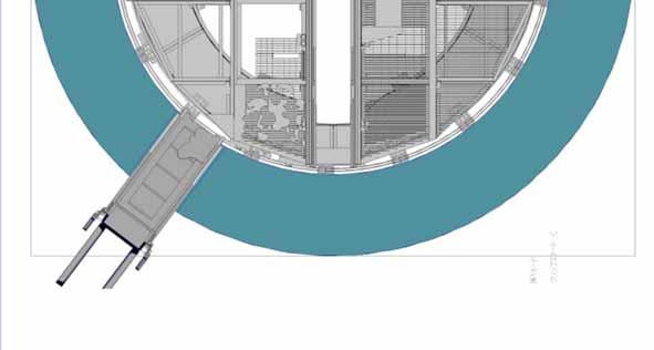
2 1. Primary containment vessel internal investigation overview Investigation Overview : The investigation focused on the area beneath the platform where fuel debris might be present. (January 2018) Scope of this investigation Fallen grating 1 Control rod drive mechanism (CRD) replacement rails Primary Containment Vessel(PCV) Pedestal Pedestal opening RPV Fallen grating 2(No hole) Control rod drive mechanism (CRD) housing Platform Approx. 7.2m Containment vessel penetration used for this investigation (X-6 penetration) Scope of PCV internal investigation implemented this time Subfloor Worker access opening 1

 2017 investigation) 2Control rod drive mechanism (CRD)")


3 2. Scope of access of survey unit Pedestal opening Survey unit Telescopic survey device Piece of fallen grating 2 Piece of fallen grating 1 (Seen during January (Seen during January 2017 investigation) 2017 investigation) 2Control rod drive mechanism (CRD) housing 1Platform Control rod drive mechanism (CRD) replacement rails Top of platform Approx. 3.2m Approx. 0.3m Approx.. 2.0m Control rod drive mechanism (CRD) replacer Worker access opening 3Mid-level work platform 4Bottom of pedestal Bottom of pedestal Scope of access of survey unit this time Cable tray 2

.")
 were found to be damaged and fallen, which may indicate the path of the fallen fuel debris in consideration of the")
 investigation) Tilted grating Direction of camera Blind spots in the")


 :Measures the level of neutron flux in the")
4 3. Investigation results 1Top of Platform Pedestal opening CRD replacer LPRM cable PIP cable Pedestal wall Scope of fallen grating Scope of remaining grating Piece of fallen grating CRD replacer Slot opening TIP guide tube Pedestal wall Platform frame Piece of fallen grating 1 (Seen during January 2017 investigation) No significant damage was seen to the CRD replacer or platform frame, etc., and the conditions of these objects remain unchanged from the last investigation (January 2017). Structures in the foreground of the camera image (TIP guide tube, PIP cable and grating, etc.) were found to be damaged and fallen, which may indicate the path of the fallen fuel debris in consideration of the relatively large amount of adhered substances on top of the platform frame. Piece of fallen grating 2 (Seen during January 2017) investigation) Tilted grating Direction of camera Blind spots in the background of the camera image prevent observation of structure deformation or damage, as well as the conditions of the fallen grating and adhered substances. As with the previous investigation (January 2017) no damage was seen to the inner walls of the pedestal within the scope of the observed area. No image taken for this area Adhered substance (above frame) Piece of fallen grating 2 (Seen during January 2017) Grating Fallen grating 1 cannot be seen in this image LPRM(Local Power Range Monitor) :Measures the level of neutron flux in the reactor TIP (Traversing In-core Probe) :Used to calibrate the LPRM PIP (control rod Position Indicator Probe) :Used to detect the position of the control rods (Reference) Inside Unit 2 pedestal Image source and rendering: International Research Institute for Nuclear Decommissioning(IRID) 3

 Camera direction Area directly above fallen grating")


 Within the scope that was")

5 3. Investigation results 2Around CRD housing (1/2) CRD housing Enlarged In foreground of camera image In foreground of camera image CRD flange Hanger rod Support bar Piece of fallen grating 1 (Seen during January 2017 investigation) Camera direction Area directly above fallen grating 1 In background of camera image (Reference) Unit 5 CRD housing In background of camera image Hanger rod, Support bar :Meant to support the load of the CRD (Control Rod Drive Mechanism) housing if it falls The CRD housing supports directly above the piece of fallen grating 1 shows no significant deformation or damage and remains unchanged since the last investigation (January 2017) Within the scope that was investigated none of the CRD housing supports appear to have fallen. Image source and rendering: International Research Institute for Nuclear Decommissioning(IRID) 4
 Inside Unit 5")


6 3. Investigation results 2Around CRD housing (2/2) In foreground of CRD housing Camera direction Enlarged camera image PIP cables and LPRM cables obscured by adhered substance CRD flange Hanger rod PIP cable Support bar In background of camera image (Reference) Inside Unit 5 pedestal Parts of the TIP guide tube, PIP cables and LPRM cables could not CRD housing Bottom of CRD Support bracket LPRM ケーブル cables be observed due to adhered substances. PIP cables The grating directly below the areas where parts of the TIP guide tube, PIP cables and LPRM cables could not be observed was found to have fallen. LPRM(Local Power Range Monitor) :Measures the level of neutron flux in the reactor Pedestal Underground access hole Platform CRD replacer Flat bar Slot opening Image source and rendering: International Research Institute for Nuclear Decommissioning(IRID) 5


 It was confirmed that the grating (Sections A~C) in the foreground of the")

7 3. Investigation results 3Mid-level work platform Grating section D has yet to be surveyed Piece of fallen grating 2 Mid-level work platform Section C Mid-level work platform Section B (Area directly below fallen grating 2) Platform Rotation motor A B C D Mid-level work platform Mid-level work platform Section A Checking fallen pieces of grating Camera direction Adhered substance Mid-level work platform frame Image source and rendering: International Research Institute for Nuclear Decommissioning(IRID) It was confirmed that the grating (Sections A~C) in the foreground of the location where the camera was lowered has fallen. Locations where Section B and C grating has fallen show the same conditions as the platform. No significant deformation or damage was seen to the mid-level work platform frame 6
 Worker access opening Adhered")


 During Unit 2 outage This structure was removed from inside the PCV when the")
8 3. Investigation results 4Bottom of pedestal (1/4) Condition of structures and distribution of deposits Piece of fallen grating 1 (Seen during January 2017 investigation) Worker access opening Adhered substance (Mid-level work platform frame) Slot opening CRD replacer rotating frame Worker access opening Mid-level work platform frame Strut Side of cable tray CRD replacer elevator Area around cable trays that was checked Camera direction Bolt remover No significant deformation or damage was seen to structures such as the CRD replacer rotating frame, mid-level work platform frame, struts, or cable trays, etc. Pebble and clay-like deposits cover the entire bottom of the pedestal. Although the deposits appear to be solidified molten material, it is possible that the temperature of the deposits when this substance started to accumulate on top of the cable tray was not hot enough to cause deformation of the cable trays in consideration of the fact that no deformation of the cable trays (4mm thick stainless steel) could be observed. Cable tray (Reference) During Unit 2 outage This structure was removed from inside the PCV when the reactor was in operation Image source and rendering: International Research Institute for Nuclear Decommissioning(IRID) 7


9 3. Investigation results 4Bottom of pedestal (2/4) Cooling water injection status Piece of fallen grating 1 (Seen during January 2017 investigation) Puddles Puddle CRD replacer elevator Puddle Puddle Deposits above cable tray Cable tray notch Cable tray notch Camera direction Considering that cooling water is pouring in and that the temperature around the bottom of the pedestal is approximately 21 it is assumed that the deposits are being kept cool and stable by the cooling water thatʼs being injected. Puddles were found on the side of the worker access opening and in cable trays through the cable tray notches. Bolt remover Cable tray notch (Reference) During Unit 2 outage This structure was removed from inside the PCV when the reactor was in operation Image source and rendering: International Research Institute for Nuclear Decommissioning(IRID) 8
 Resting position of fallen top tie plate(near pedestal inner wall) Resting position of fallen spring-like objects Side of")
 Unit 5 elevator When looking at the center of the pedestal")
 was not clearly defined thereby suggesting that the height of deposits in this area may exceed 70cm at some points.")

 could be")

10 3. Investigation results 4Bottom of pedestal (3/4) Detailed look at deposit distribution (1) Camera direction Piece of fallen grating 1 (Seen during January 2017 investigation) Resting position of fallen top tie plate(near pedestal inner wall) Resting position of fallen spring-like objects Side of cable tray Worker access opening Puddle Puddle CRD replacer elevator Area where deposits are relatively high (Directly below fallen platform grating 1) Resting place of fallen pipe-like object Resting place of fallen rod-like object (Reference) Unit 5 elevator When looking at the center of the pedestal from the location of the lowered camera the step in elevation that should be present around the cable tray on the left side (approximately 70cm in height) was not clearly defined thereby suggesting that the height of deposits in this area may exceed 70cm at some points. The height of deposits around the CRD replacer elevator appears to be between 40cm to 50cm considering the extent to which the elevator is buried. Furthermore, when looking from the position where the camera was lowered, it was confirmed that the height of the deposits in the area behind the elevator are lower than the cable tray. When viewing the left side of the center of the pedestal from the location where the camera was lowered parts of a fuel assembly (top tie plate) could be seen and fallen objects shaped like rods, pipes, and springs, could be seen in the vicinity. Furthermore, since the height of deposits in this area is higher than that in the surrounding Approx. 50 cm areas, it is possible that the area directly above this location marks one of the paths by which fuel debris fell. Height of deposits in which the CRD replacer elevator is buried Image source and rendering: International Research Institute for Nuclear Decommissioning(IRID) 9
 Piece of fallen grating 1 (Seen during January")


11 3. Investigation results 4Bottom of pedestal (4/4) Detailed look at deposit distribution (2) Piece of fallen grating 1 (Seen during January 2017 investigation) Camera direction Side of cable tray Area where deposits may be higher than other areas Worker access opening Side of cable tray Cable tray side CRD replacer elevator Resting place of fallen rod-like object Area shown in photo on the right Area where deposits may be higher than other areas Resting place of fallen grating-like object Spots where the height of deposits may be higher than those in the surrounding area were found near the worker access opening. Considering the distribution of these deposits it is possible that there may be multiple locations at which fuel debris fell in addition to the location to the left of the center of the pedestal when looking from the position of the lowered camera. Grate-like fallen objects were found in the vicinity of the location where the height of deposits may be higher than the surrounding area. Rod-shaped falling objects were found near the cable tray. Resting place of fallen rod-like object In regards to the conditions outside the worker access opening, it cannot be confirmed whether or not deposits leaked outside of the pedestal because this area cannot be seen in the images obtained during this investigation. Resting place of fallen grating-like object Image source and rendering: International Research Institute for Nuclear Decommissioning(IRID) 10


12 3. Investigation results 5Bottom of pedestal (pedestal wall) Pedestal Area not surveyed yet Worker access opening 1 2 Cable tray Position where camera was lowered to 3 4 CRD replacer rotating frame Although the epoxy paint is flaking off and the surface is rough, no significant deformation or damage was found to the inner walls of the pedestal. Image source: International Research Institute for Nuclear Decommissioning(IRID) 11

13 4. Inscription on top tie plate Part of fuel assembly (top tie plate) Pedestal inner wall Part of fuel assembly (top tie plate) Pebble-like deposits The inscription on the top type plate found at the bottom of the pedestal was examined in order to find out the charging location of the fuel assembly from which it came. Starting from the left the following four letters/numbers could be read: F2XN However, since the serial number, which starts with the fifth letter in this series could not be seen we were unable to identify the charging location of the fuel assembly from which this top tie plate originated. Location of inscription Inscription The inscriptions on fuel assemblies charged into Unit 2 are between five to eight digits long (Plant name (F2)) + (Purchase period (V~AB)) + (Abbreviation for seller (N)) + (serial number (1 )) Image source: International Research Institute for Nuclear Decommissioning(IRID) Image rendering: Tokyo Electric Power Company Holdings, Inc. 12


14 Supplement 1 Fuel assembly charging position 132 out of the total 548 fuel assemblies that were in the reactor begin with the inscription F2XN and are followed by a serial number. The locations of these fuel assemblies are shown in the diagram below. Concept diagram of fuel assembly location Location where top tie plate was found CRD replacement rails Charing location of fuel assembly marked as F2XN Charging location of fuel support bracket plug There is no F2XN inscription on the fuel support bracket plug 13
15 5. Conclusion (1/2) <Results of this investigation> Above the platform the structures in the foreground of the image taken with the lowered camera (TIP guide tube, PIP cable, and grating, etc.) have been significantly damaged and/or have fallen, and a relatively large amount of adhered substances were found on top of the frame. On the mid-level work platform grating in the foreground of the images taken with the lowered camera were found to have fallen, much like the conditions above the platform. At the bottom of pedestal no significant deformation was seen to the CRD replacer rotating frame, midlevel work platform frame, struts, or cable tray, etc. Furthermore, considering that cooling water is pouring in and that the temperature around the bottom of the pedestal is approximately 21 it is assumed that the deposits are being kept cool and stable by the cooling water thatʼs being injected. Since the height of the deposits at the bottom of the pedestal is higher on the left side of the center of the pedestal when viewed from the position of the lowered camera, it is possible that the area directly above this location may be one of the paths by which fuel debris fell. At the same time, since deposits on the side of the worker access opening are higher than in the surrounding area it is possible that there are multiple paths by which fuel debris fell. In regards to the conditions outside the worker access opening, it cannot be confirmed whether or not deposits leaked outside of the pedestal because this area cannot be seen in the images obtained during this investigation. 14
16 5. Conclusion (2/2) < Results of this investigation (cont.)> Although the epoxy paint is flaking off and the surface is rough, no significant deformation or damage was found to the inner walls of the pedestal. The inscription on the top tie plate that was found to have fallen to the bottom of the pedestal could not be read completely thereby preventing the charging location of the fuel assembly from which it originated from being identified. <Measures going forward> Since this investigation yielded information about the conditions at the bottom of the pedestal and the structures that exist between the platform and the bottom of the pedestal, we are deliberating the implementation of another investigation using an armshaped access/survey device that can be reinserted through the X-6 penetration to perform a multipurpose survey in order to ascertain dose rate distributions and a detailed distribution of structures inside the PCV which are necessary in order to deliberate methods for removing the debris. 15


17 Supplement 2 Condition of structures and adhered substances found inside the pedestal (1/3) Above Platform Area not surveyed yet CRD replacer Pedestal Condition of grating unknown Piece of fallen grating 2 Platform Piece of fallen grating 1 Tilted grating No obstacles above slot opening Conditions above platform :Adhered substance :Location of fallen grating :Location where grating remains :Camera direction 16


18 Supplement 2 Around the mid-level work platform Condition of structures and adhered substances found inside the pedestal (2/3) Pedestal Cable tray Area not surveyed yet Mid-level work platform Area directly below fallen grating 2 D C Adhered substance B A :Adhered substance :Location of fallen grating :Location where grating remains Mid-level work conditions above platform :Camera direction 17
 Bottom of pedestal Pedestal :Camera direction Cable tray Area not")


19 Supplement 2 Condition of structures and adhered substances found inside the pedestal (3/3) Bottom of pedestal Pedestal :Camera direction Cable tray Area not surveyed yet Worker access opening Deposits above cable tray Area not surveyed yet Worker access opening Location of rodlike fallen object 2 Puddles found Deposits exceed height of cable tray Area where deposits are higher than in other areas Location where cooling water is pouring in Location of spring and rod-like fallen object 1 Location of fallen grate-like object Deposits lower than height of cable tray Location of tie plat and pipe-like fallen object Water surface seen Area where deposits are higher than in other areas CRD replacer rotating frame Puddles and fallen objects found at the bottom of the pedestal Deposits found at the bottom of the pedestal 18


20 Supplement 3 Equipment for accessing and surveying the PCV through the X-6 penetration We are deliberating the implementation of another investigation using an arm-shaped access/survey device that can be reinserted through the X-6 penetration to perform a multipurpose survey in order to ascertain dose rate distributions and a detailed distribution of structures inside the PCV X-6 Isolation valve Pedestal penetration Pedestal Access/survey device X-6 penetration Access/survey device Moves back and forth Proposal for setting up access/survey equipment in front of the X-6 penetration Axis of rotation Telescopic arm PCV Tilt axis Head rotation axis Arm-shaped access/survey device CRD rails Tilt axis CRD rails Pedestal opening PCV PCV side How access/survey equipment shall be used inside the PCV 19


21 Reference 1-1: Other observed structures Fallen object above rotation rails <Visible external characteristics> An object resembling the handle of the top tie plate was found to have fallen on top of the platform rotation rails <Estimated dimensions> Using the height of the rotation rails (approximately 7 cm) as reference, the thickness of the object thought to be the handle was estimated to be approximately 1cm which matches the design dimensions of the handle. <Confirmed facts> No identifying characteristics of the handle could be seen Fallen object above platform rotation rails Piece of fallen grating 2 Approx. 7 cm Platform rotation rails Camera direction Platform rotation rails Rotation rail support bracket Fallen object above platform rotation rails Image source: International Research Institute for Nuclear Decommissioning(IRID) 20
22 Reference 1-2:Other observed structures Pipe-like fallen objects <Visible external characteristics> A pipe-shaped fallen object was found near the location where the top tie plate has fallen at the bottom of the pedestal. A diameter difference can be seen at the end of this object <Estimated dimensions> Using the top tie plate width (approximately 1cm) as reference the width of this pipe was estimated at approximately 2cm. <Confirmed facts> The object could not be identified based upon the visible external characteristics and estimated dimensions Pipe-like fallen objects Diameter difference can be seen at end Resting place of fallen top tie plate Camera direction Top tie plate Enlarged photo Image source: International Research Institute for Nuclear Decommissioning(IRID) 21


23 Reference 1-3:Other observed structures Spring-like fallen objects <Visible external characteristics> A spring-shaped fallen object was found near the location where the top tie plate has fallen at the bottom of the pedestal. <Estimated dimensions> There were no structures that could be used as reference for estimating the dimensions of this object so the dimensions were not estimated. This spring has a relatively small diameter and more than 15 coils. <Confirmed facts> SRNM detectors, LPRM detector and fuel assemblies all use small diameter springs with more than 15 coils, but it could not be determined from what structure this object originated. Location of spring-like fallen objects SRNM (Startup Range Neutron Monitor): Measures the level of neutron flux in the reactor during startup Resting place of fallen top tie plate Camera direction Enlarged photo Image source: International Research Institute for Nuclear Decommissioning(IRID) 22

24 Reference 1-4:Other observed structures Rod-like fallen object (around springs) <Visible external characteristics> A rod-like fallen object was found near the spring-like fallen object at the bottom of the pedestal. <Estimated dimensions> There were no structures that could be used as reference for estimating the dimensions of this object so the dimensions were not estimated. <Confirmed facts> The object does not have sufficient dimensions or structural characteristics to aid in identification. Location of rod-like fallen object (around location of fallen spring) Springs Camera direction Rod-like fallen object Image source: International Research Institute for Nuclear Decommissioning(IRID) 23


25 Reference 1-5:Other observed structures Rod-like fallen object <Visible external characteristics> A Rod-shaped fallen object was found at the bottom of the pedestal. The rod portion of the fallen object appears to have different diameters. <Estimated dimensions> There were no structures that could be used as reference for estimating the dimensions of this object so the dimensions were not estimated. <Confirmed facts> The object does not have sufficient dimensions or structural characteristics to aid in identification. Rod-like fallen object Camera direction Location of rod-like fallen object Image source and rendering: International Research Institute for Nuclear Decommissioning(IRID) 24


26 Reference 1-6:Other observed structures Grate-like fallen object <Visible external characteristics> Plate-like fallen objects were found near the CRD replacer elevator at the bottom of the pedestal. These fallen objects appear to have grating and are buried in deposits. The objects also appear to be deformed. Enlarged photo <Estimated dimensions> There were no structures that could be used as reference for estimating the dimensions of this object so the dimensions were not estimated. <Assessment results> This object is assumed to be grating based on the visible external characteristics. If it is assumed that this grating fell from directly above then it must be from the mid-level work platform because the grating on the platform still remains. However, the mid-level work platform has only been partially examined so it was impossible to identify the location from which this grating originated. Fallen object Grating-like pattern observable Camera direction Resting place of fallen grate-like object Reference :Platform grating Image source: International Research Institute for Nuclear Decommissioning(IRID) 25

![3m Measurement Point a CRD housing CRD replacer Platform Measurement point Dose rate 1 2 [Gy/h] Temp. 2 [ ] a 7 21.0 b 8 21.](/docs-images/81/82708317/images/27-1.jpg "0 CRD replacement rails Top of platform Approx. 3.2m Approx. 0.4m Approx. 1.0m Approx. 0.6m Measurement Point b Measurement Point c Measurement Point d c 8 21.0 d 8 21.")
27 Reference 2:Dose rate and temperature measurements from inside the pedestal Telescopic survey device Piece of fallen grating 1 confirmed during Piece of fallen grating 2 confirmed during January 2017 investigation January 2017 investigation Approx. 0.3m Measurement Point a CRD housing CRD replacer Platform Measurement point Dose rate 1 2 [Gy/h] Temp. 2 [ ] a b CRD replacement rails Top of platform Approx. 3.2m Approx. 0.4m Approx. 1.0m Approx. 0.6m Measurement Point b Measurement Point c Measurement Point d c d :Calibrated using Cs-137 radiation source 2:Degree of error: Dosimeter:±7% Temp. gauge: ±0.5 Bottom of pedestal Cable tray tray 26
 Fuel assembly diagram 27")
28 Reference 3:Overview of fuel assembly parts (top tie plate) Top tie plate (Holds fuel rods together) Fuel rods Water channel Spacer Channel box Bottom tie plate Overview of fuel assembly parts (top tie plate) Fuel assembly diagram 27
29 Reference 4:Example of equipment that uses springs (SRNM detector) Up Spring (diameter: Approx. 2cm) Used to attach tip of SRNM detector to location of attachment (device attached using elastic force of spring) External view of SRNM detector 28
30 Reference 5: Images obtained during January 2017 investigation Piece of fallen grating 2 CRD replacer Pedestal wall Location of fallen grating Tilted grating Piece of fallen grating 1 (Position is approximate since it is not visible in the attached photo) Photo not yet rendered in this location Image source and rendering: International Research Institute for Nuclear Decommissioning(IRID) 29


31 Reference 6:Structures inside the pedestal Platform frame Platform rotation rail CRD rails Rotation rail support bracket Worker access opening 30

 Control")

32 Reference 7:Core internals Reactor Pressure Vessel (RPV) Control Rods CR guide tube Pedestal CRD housing 31
FP release behavior at Unit-2 estimated from CAMS readings on March 14 th and 15 th
 Attachment 2-11 FP release behavior at Unit-2 estimated from CAMS readings on March 14 th and 15 th 1. Outline of the incident and the issue to be examined At Unit-2 of the Fukushima Daiichi NPS, the reactor
TEPCO s Activities on the Investigation into Unsolved Issues in the Fukushima Daiichi NPS Accident
 2015 The Tokyo Electric Power Company, INC. All Rights Reserved. 0 TEPCO s Activities on the Investigation into Unsolved Issues in the Fukushima Daiichi NPS Accident IAEA IEM8 Vienna International Centre,
Detection of Xe135 at Nuclear Reactor of Unit 2, Fukushima Daiichi Nuclear Power Station. November 4, 2011 Tokyo Electric Power Company
 Detection of Xe135 at Nuclear Reactor of Unit 2, Fukushima Daiichi Nuclear Power Station November 4, 2011 Tokyo Electric Power Company On November 1, as a sampling result by the gas control system that
Miniball Flexible Frame
 Miniball Flexible Frame Author: Nigel Warr Date: 6 th March 2015. Contents 1 Overview 2 2 Modifications 3 2.1 Modifications to the height..................................... 3 2.2 Modifications to the
DEVELOPMENT OF DROP WEIGHT IMPACT TEST MACHINE
 CHAPTER-8 DEVELOPMENT OF DROP WEIGHT IMPACT TEST MACHINE 8.1 Introduction The behavior of materials is different when they are subjected to dynamic loading [9]. The testing of materials under dynamic conditions
Employees Contractors
 Attachment Exposure Dose Distribution 1. Effective Dose from External Exposure Table 1 shows the distribution of external exposure dose of workers who were involved in radiation work at the Fukushima Daiichi
Cat. Multi-Processors. Hydraulic Excavators. Multi-Processor/Hydraulic Excavator Compatibility. Features: Maximum Productivity.
 Cat Multi-Processors Hydraulic Excavators Maximum Productivity Big challenges are reduced to small pieces, thanks to high cutting and crushing forces generated by the cross-mounted cylinder. High productivity
Correlation between neutrons detected outside the reactor building and fuel melting
 Attachment 2-7 Correlation between neutrons detected outside the reactor building and fuel melting 1. Introduction The Fukushima Daiichi Nuclear Power Station (hereinafter referred to as Fukushima Daiichi
Employees Contractors
 Attachment Exposure Dose Distribution 1. Effective Dose from External Exposure Table 1 shows the distribution of external exposure dose of workers who were involved in radiation work at the Fukushima Daiichi
product manual H-3220A Benkelman Beam
 05.12 product manual H-3220A Benkelman Beam General The H-3220A Benkelman Beam Apparatus is a convenient and accurate device used for measuring the deflection of flexible pavements under moving wheel
x Builders Level Service Manual
 40-690 22x Builders Level Service Manual Item Description Pages.0 Overall Instrument Assembly 2. Main Assembly 2.2 Telescope Assembly 3.3 Base Assembly 4.4 Frame Assembly 5 2.0 Calibration 6-8 2. Vial
October 2017 November Employees Contractors
 Attachment Exposure Dose Distribution 1. Effective Dose from External Exposure Table 1 shows the distribution of external exposure dose of workers who were involved in radiation work at the Fukushima Daiichi
A PRELIMINARY ALIGNMENT PLAN FOR RIA AT MSU
 IWAA2004, CERN, Geneva, 4-7 October 2004 A PRELIMINARY ALIGNMENT PLAN FOR RIA AT MSU D. P. Sanderson, NSCL-MSU, 1 Cyclotron Lab, East Lansing, MI 48824, USA 1. INTRODUCTION The Rare Isotope Accelerator
SECTION 1 - WHAT IS A BTU METER? BTU's = Flow x ΔT Any ISTEC BTU Meter System consists of the following main components:
 SECTION 1 - WHAT IS A BTU METER? ISTEC BTU Meters measure energy usage by multiplying flow rate and temperature difference. As the water (or other liquid) passes through these lines, the multi-wing turbine
Galileo Telescope Solar Viewer Joseph Hora, Elizabeth Hora 2017/09/18
 Galileo Telescope Solar Viewer Joseph Hora, Elizabeth Hora 2017/09/18 17 7.75 5 2 1.5 3 2 1.5 Materials: (all dimensions in inches) 3x plywood sheet 17 x 7.75 x ½ 3x wood block cut from 2x4: 5 x 2 x 1.5
1. What would be the dose rate of two curies of 60Co with combined energies of 2500 kev given off 100% of the time?
 1.11 WORKSHEET #1 1. What would be the dose rate of two curies of 60Co with combined energies of 500 kev given off 100% of the time?. What would be the dose rate of 450 mci of 137Cs (gamma yield is 90%)?
Vibration-Free Pulse Tube Cryocooler System for Gravitational Wave Detectors I
 1 Vibration-Free Pulse Tube Cryocooler System for Gravitational Wave Detectors I - Vibration-Reduction Method and Measurement - T. Tomaru A, T. Suzuki A, T. Haruyama A, T. Shintomi A, N. Sato A, A. Yamamoto
McQuay Climate Control Singer
 Replacement Parts List No. 055204800 Revision B 01/2017 McQuay Climate Control Singer Vertical Water Source Heat Pump FC, FG, FW 240, 330, 400, 500 Vintages C, D Last Manufactured: 1986 To find your Daikin
Special edition paper
 Development of New Aseismatic Structure Using Escalators Kazunori Sasaki* Atsushi Hayashi* Hajime Yoshida** Toru Masuda* Aseismatic reinforcement work is often carried out in parallel with improvement
Characterization of Large Structures & Components
 Structures & Components KEY BENEFITS Key Drivers: Lack of good knowledge about the position, the identification and the radiological specification of contamination on or inside large components. Significant
OPERATIONS SUPPLEMENT FOR THE COMPARISON AUTOCOLLIMATOR, D600
 STANFORD UNIVERSITY W.W. HANSEN EXPERIMENTAL PHYSICS LABORATORY GRAVITY PROBE B, RELATIVITY GYROSCOPE EXPERIMENT STANFORD, CALIFORNIA 94305-4085 P0354 SU/GP-B P0354 OPERATIONS SUPPLEMENT FOR THE COMPARISON
The Secret Behind the Nobeyama 45-m Radio Telescope s Excellent
 The Secret Behind the Nobeyama 45-m Radio Telescope s Excellent Even now over 30 years after its completion in 1982, the 45 m diameter radio telescope at NAOJ s Nobeyama Radio Observatory boasts world
STUD & TRACK ROLL FORMING MACHINE
 STUD & TRACK ROLL FORMING MACHINE R O L L F O R M E R S U S A I W W W. R O L L F O R M E R S - U S A. C O M Page1 Cantilevered Dual Headed 6,000 lb Decoiler Includes mandrel and stand Can accommodate 22
Analysis for Progression of Accident at Fukushima Dai-ichi Nuclear Power Station with THALES2 code
 Analysis for Progression of Accident at Fukushima Dai-ichi Nuclear Power Station with THALES2 code Toshinori MATSUMOTO, Jun ISHIKAWA, and Yu MARUYAMA Nuclear Safety Research Center, Japan Atomic Energy
The Dynamical Loading of the WWER440/V213 Reactor Pressure Vessel Internals during LOCA Accident in Hot and Cold Leg of the Primary Circuit
 The Dynamical Loading of the WWER440/V213 Reactor Pressure Vessel Internals during LOCA Accident in Hot and Cold Leg of the Primary Circuit ABSTRACT Peter Hermansky, Marian Krajčovič VUJE, Inc. Okružná
CRYOGENIC CONDUCTION COOLING TEST OF REMOVABLE PANEL MOCK-UP FOR ITER CRYOSTAT THERMAL SHIELD
 CRYOGENIC CONDUCTION COOLING TEST OF REMOVABLE PANEL MOCK-UP FOR ITER CRYOSTAT THERMAL SHIELD K. Nam, a D. K. Kang, a W. Chung, a C. H. Noh, a J. Yu, b N. I. Her, b C. Hamlyn-Harris, b Y. Utin, b and K.
Instructions for Parts Books
 Instructions for Parts Books The heading at the top of the page will be the same for the picture of the parts at it is for the page with the part numbers. Definition of column headings on part number pages:
Instruction Manual. Kite-22 Camera Crane Starter Package (KITE-22-STARTER) Exclusive of Weights
 Exclusive of Weights") Instruction Manual Kite-22 Camera Crane Starter Package (KITE-22-STARTER) Exclusive of Weights All rights reserved No part of this document may be reproduced, stored in a retrieval system, or transmitted
Instruction Manual Kite-22 Camera Crane Starter Package (KITE-22-STARTER) Exclusive of Weights All rights reserved No part of this document may be reproduced, stored in a retrieval system, or transmitted
LUDLUM MODEL 42-5 NEUTRON BALL CART. August 2015 Serial Number PR and Succeeding Serial Numbers
 LUDLUM MODEL 42-5 NEUTRON BALL CART August 2015 Serial Number PR149512 and Succeeding Serial Numbers LUDLUM MODEL 42-5 NEUTRON BALL CART August 2015 Serial Number PR149512 and Succeeding Serial Numbers
WM2013 Conference, February 24 28, 2013, Phoenix, Arizona, USA
 The Underwater Spectrometric System Based on CZT Detector for Survey of the Bottom of MR Reactor Pool 13461 Victor Potapov, Alexey Safronov, Oleg Ivanov, Sergey Smirnov, Vyacheslav Stepanov National Research
ALIGNMENT OF THE MSGC BARREL SUPPORT STRUCTURE
 ALIGNMENT OF THE MSGC BARREL SUPPORT STRUCTURE Kari Tammi*, Miikka Kotamäki*, Antti Onnela+, Tommi Vanhala* *HIP, Helsinki Institute of Physics, CERN/EP, CH-1211 GENEVA + CERN, European Laboratory for
SUB-CHAPTER D.1. SUMMARY DESCRIPTION
 PAGE : 1 / 12 CHAPTER D. REACTOR AND CORE SUB-CHAPTER D.1. SUMMARY DESCRIPTION Chapter D describes the nuclear, hydraulic and thermal characteristics of the reactor, the proposals made at the present stage
RYOBI 10 in. TABLE SAW MODEL NUMBER BTS21
 0 1 1 1 1 1 1 1 SEE FIGURE A 1 1 1 1 1 1 1 1 SEE FIGURE C 1 1 1 1 0 1 SEE FIGURE E 1 SEE FIGURE D 1 1 10 1 0 1 1 1 1 1 1 0 1 1 1 1 1 1 1 1 1 1 1 0 1 1 1 1 1 1 1 1 1 0 1 0 1 10 1 0 1 1 0 1 1 SEE FIGURE
LOW PROFILE TRANSFERS
 LOW PROFILE TRANSFERS PARTS CATALOG 1 INDUSTRIAL DRIVE PO BOX 0 SWIFT CURRENT, SASKATCHEWAN, CANADA SH 0L0 PHONE:.66. (NORTH AMERICA) FAX: 06.. WEBSITE: HTTP://WWW.BATCOMFG.COM EMAIL: SALES@BATCO-REM.COM
Neutronics calculations for the ITER Collective Thomson Scattering Diagnostics
 Neutronics calculations for the ITER Collective Thomson Scattering Diagnostics 17 th Meeting on Reactor Physics in the Nordic Countries Göteborg, Sweden May 11-12, 2015 E. Nonbøl 1, E. Klinkby 1, B. Lauritzen
Reliability and Traceability in Radiation Calibration
 Reliability and Traceability in Calibration Sadao Nakashima Teruo Ebato 1. Introduction Fuji Electric has a successful history of delivering radiation measuring equipment used in the controlled areas of
THE LOSMANDY G-11 MOUNT
 Checking the parts THE LOSMANDY G-11 MOUNT Depending on which accessories you ordered, your G-11 mount was shipped in four or more boxes. The contents of each box are as follows: Equatorial Mount Adjustable
OASIS WIRELESS WEATHER STATION
 User Manual 3910-B Royal Avenue, Simi Valley, Ca 93063 805-527-4498 RMIS Part No. 500760 TABLE OF CONTENTS INTRODUCTION General Description 3 General Precautions 3 INSTALLATION Base Preparation 6 Tower
INSTALLATION INSTRUCTIONS FRONT PLOW MOUNT KIT Part Number: Application: Polaris Sportsman 400, 500, 800
 WARN INDUSTRIES, INC. 12900 S.E. Capps Road, Clackamas, OR USA 97015-8903, 1-503-722-1200, FAX: 1-503-722-3000 Customer Service: 1-800-543-9276 Dealer Locator Service: 1-800-910-1122 International Sales/Customer
ERMSAR Results and Progress of Fundamental Research on FP Chemistry. Japan Atomic Energy Agency. May16-18, 2017 Warsaw, Poland
 8 TH CONFERENCE ON SEVERE ACCIDENT RESEARCH ERMSAR 2017 Results and Progress of Fundamental Research on FP Chemistry M.Osaka, K.Nakajima, S. Miwa, F.G.Di Lemma, N.Miyahara, C.Suzuki, E.Suzuki, T.Okane,
Installation Manual For Habu 32 Struts F4 Struts Habu 2 Struts
 Installation Manual For Habu 32 Struts F4 Struts Habu 2 Struts Note: This manual is intended for those who have the E- Flite 15-25 size electric retracts. Index Nose Strut Step 1. Step 2. Step 3. Step
HIMARC Simulations Divergent Thinking, Convergent Engineering
 HIMARC Simulations Divergent Thinking, Convergent Engineering 8117 W. Manchester Avenue, Suite 504 Los Angeles, CA 90293 Ph: (310) 657-7992 Horizontal Superconducting Magnet, ID 1.6m 1 1 Design definition
G-FIRE FLANGE ADAPTERS
 G-FIRE FLANGE ADAPTERS 21 G-FIRE FLANGE ADAPTERS Pictorial Table of Contents MATERIAL SPECIFICATIONS Issue 03, 04, 07 Cert No. 570, 669, 673 For detailed Listing and Approval information see pages 101-10
Visit any one of our 30 locations or visit us on line at
 TYPE IA ALUMINUM 2886509079 2886501870 2886510013 2886510010 2886510014 2886504441 AS3002 2' TYPE IA AS3003 3' TYPE IA AS3004 4' TYPE IA AS3006 6' TYPE IA AS3008 8' TYPE IA AS3010 10' TYPE IA 34.99 57.99
DEVELOPMENT OF HIGH RESOLUTION X-RAY CT TECHNIQUE FOR IRRADIATED FUEL ASSEMBLY
 More Info at Open Access Database www.ndt.net/?id=18598 DEVELOPMENT OF HIGH RESOLUTION X-RAY CT TECHNIQUE FOR IRRADIATED FUEL ASSEMBLY A. Ishimi, K. Katsuyama, H. Kodaka, H. Furuya Japan Atomic Energy
Gas Manifold Installation
 Rheinisch Gas Manifold Installation Mounting of Gas Manifold at FRONT and REAR of CMS DT Muon chamber Definitions for MB, MB, MB, MB4,..., for each +Z and Z Types and for Services at Left and at Right
Coflore Agitated Cell Reactor
 Coflore Agitated Cell Reactor Coflore ACR The Coflore ACR is a lab flow reactor developed by AM Technology for studying chemistry in flow and developing scalable continuous processes. Its flexible design
THREE HOLE SPLICE CLEVIS FOR B52 Standard finishes: ZN, GRN Wt./C 126 Lbs. (57.1 kg)
") CLEVIS FITTINGS B169 TWO HOLE SPLICE Wt./C 84 Lbs. (38.1 kg) B168 THREE HOLE SPLICE Wt./C 126 Lbs. (57.1 kg) B167 Wt./C 178 Lbs. (80.7 kg) 3 1 /2 (88.9) B170 TWO HOLE SPLICE Wt./C 123 Lbs. (55.8 kg) 5
CLEVIS FITTINGS B169 TWO HOLE SPLICE Wt./C 84 Lbs. (38.1 kg) B168 THREE HOLE SPLICE Wt./C 126 Lbs. (57.1 kg) B167 Wt./C 178 Lbs. (80.7 kg) 3 1 /2 (88.9) B170 TWO HOLE SPLICE Wt./C 123 Lbs. (55.8 kg) 5
Lectures on Applied Reactor Technology and Nuclear Power Safety. Lecture No 6
 Lectures on Nuclear Power Safety Lecture No 6 Title: Introduction to Thermal-Hydraulic Analysis of Nuclear Reactor Cores Department of Energy Technology KTH Spring 2005 Slide No 1 Outline of the Lecture
Figure 1 Enlargement of Powdered Activated Carbon by microscope.
 Introduction The following is a description of how the Powdered Activated Carbon (PAC) dosing system operates. Firstly an overview of how the Semi Dry Reactor and the purpose of carbon injection is described.
Simulation of process of hot pilgrim rolling
 Simulation of process of hot pilgrim rolling YURY B. CHECHULIN, Doctor of Engineering Science, Professor EVGENY U. RASKATOV, Doctor of Engineering Science, Professor YURY A. POPOV, post-graduate student
TEST METHOD FOR DETERMINING BREAKAWAY FORCE OF A MAGNET
 STANDARD MDFA 101 95 TEST METHOD FOR DETERMINING BREAKAWAY FORCE OF A MAGNET DISCLAIMER: This test method was developed by representative members of the Magnet Distributor and Fabricators Association (MDFA)
ITTC Recommended Procedures and Guidelines
 and Guidelines Page 1 of 12 22 Table of Contents TUPURPOSE...UT2 TUWORK INSTRUCTION UT2 TU1 TU2 TU3 Introduction.2 Subject and Condition of Calibration...2 TU2.1UT TUSubject and Main Tools of Calibration...UT2
BETA Protecting. Low-Voltage Fuse Systems. LV HRC fuse links. 3/36 Siemens ET B1 2008
 LV HRC fuse links Overview LV HRC fuses are used for installation systems in non-residential, commercial and industrial buildings as well as in switchboards of power supply companies. They therefore protect
MEASUREMENT OF SPENT FUEL ASSEMBLIES IN SPRR-300
 MEASUREMENT OF SPENT FUEL ASSEMBLIES IN SPRR-300 CHEN Wei, HU Zhiyong, YANG Rui Institute of Nuclear Physics and Chemistry, Sichuan, China 1 Preface SPRR-300 is a pool-typed research reactor which uses
Visual Physics 218 Forces & Acceleration [Lab 3]
![Visual Physics 218 Forces & Acceleration [Lab 3]](/thumbs/77/75171410.jpg "Visual Physics 218 Forces & Acceleration [Lab 3]") In this experiment, you will be evaluating the vector nature of forces and Newton s 2 nd Law of Motion using a free-body diagram. You will accomplish this by performing experiments involving both static
In this experiment, you will be evaluating the vector nature of forces and Newton s 2 nd Law of Motion using a free-body diagram. You will accomplish this by performing experiments involving both static
10 - Celestron Telescope II: Operation
 10 - Celestron Telescope II: Operation Purpose: Gain more experience setting up a 6 Celestron telescope, familiarize yourself with the software interface, and acquire an image with the CCD camera. Due:
2 Navier-Stokes Equations
 1 Integral analysis 1. Water enters a pipe bend horizontally with a uniform velocity, u 1 = 5 m/s. The pipe is bended at 90 so that the water leaves it vertically downwards. The input diameter d 1 = 0.1
Rotary Drilling Rotary Drilling Bits
 GE 343 SUBSURFACE EXPLORATION CH 8 Rock Drilling, Testing, and Sampling Text Ch. 7. Dr. Norbert H. Maerz Missouri University of Science and Technology (573) 341-6714 norbert@mst.edu Instructional Objectives
London Examinations IGCSE
 Centre No. Candidate No. Surname Signature Initial(s) Paper Reference(s) 4420/1F London Examinations IGCSE Physics Paper 1F Foundation Tier Monday 31 October 2005 Morning Time: 1 hour 30 minutes Examiner
DEVELOPMENT OF MEASURING SYSTEM FOR STRESS BY MEANS OF IMAGE PLATE FOR LABORATORY X-RAY EXPERIMENT
 Copyright JCPDS - International Centre for Diffraction Data 003, Advances in X-ray Analysis, Volume 46. 6 DEVELOPMENT OF MEASURING SYSTEM FOR STRESS BY MEANS OF IMAGE PLATE FOR LABORATORY X-RAY EXPERIMENT
NATURAL CONVECTION HEAT TRANSFER CHARACTERISTICS OF KUR FUEL ASSEMBLY DURING LOSS OF COOLANT ACCIDENT
 NATURAL CONVECTION HEAT TRANSFER CHARACTERISTICS OF KUR FUEL ASSEMBLY DURING LOSS OF COOLANT ACCIDENT Ito D*, and Saito Y Research Reactor Institute Kyoto University 2-1010 Asashiro-nishi, Kumatori, Sennan,
PREX Background Simulation Update
 PREX Background Simulation Update Rakitha Beminiwattha Syracuse University rakithab@jlab.org 1 Outline PREX-II Collimator Plastic Shielding for Neutrons PREX-II Background Radiation Activation Studies
CBRD30CP3 & BOWRD30CP INSTRUCTION MANUAL
 CBRD30CP3 & BOWRD30CP INSTRUCTION MANUAL PROLOGUE Your BSA Illuminated sight is for use on both compound and standard bows. Each version of the BSA illuminated sight has a specific reticle to help maintain
October 30-31, 2014 Paris
 October 30-31, 2014 Paris Rittal Open Rack Solution Andy Gill & Paul Clements Rittal VP Engineering (Andy), Lead Design Engineer (Paul) Rack - Overview Key Rack Features Include : - Loading to 1400KG 2
Three-dimensional RAMA Fluence Methodology Benchmarking. TransWare Enterprises Inc., 5450 Thornwood Dr., Suite M, San Jose, CA
 Three-dimensional RAMA Fluence Methodology Benchmarking Steven P. Baker * 1, Robert G. Carter 2, Kenneth E. Watkins 1, Dean B. Jones 1 1 TransWare Enterprises Inc., 5450 Thornwood Dr., Suite M, San Jose,
GP-B Telescope Determine Metering Tube Length P0364 Rev -
 Stanford University W.W. Hansen Experimental Physics Laboratory Gravity Probe B Relativity Mission Stanford, California 94305-4085 GP-B Telescope Determine Metering Tube Length P0364 Rev - March 11, 1998
HEAVY DUTY SWING-OUT VALVE
 ISO 900 REGISTERED COMPANY Akron Brass Company. 20 All rights reserved. No portion of this can be reproduced without the express written consent of Akron Brass Company. We will not be responsible for:
Neutronics calculations for the ITER Collective Thomson Scattering Diagnostics
 Downloaded from orbit.dtu.dk on: Sep 04, 2018 Neutronics calculations for the ITER Collective Thomson Scattering Diagnostics Nonbøl, Erik; Klinkby, Esben Bryndt; Lauritzen, Bent; Santos, R. Publication
VVER-1000 Reflooding Scenario Simulation with MELCOR Code in Comparison with MELCOR Simulation
 VVER-1000 Reflooding Scenario Simulation with MELCOR 1.8.6 Code in Comparison with MELCOR 1.8.3 Simulation Jiří Duspiva Nuclear Research Institute Řež, plc. Nuclear Power and Safety Division Dept. of Reactor
Task 3 Desired Stakeholder Outcomes
 Task 3 Desired Stakeholder Outcomes Colby Jensen IRP Kickoff Meeting, Nov 19-20, 2015 Instrumentation Overview Three general levels of core instrumentation: Reactor control and operation Additional reactor
Instructional Objectives
 GE 343 SUBSURFACE EXPLORATION CH 8 Rock Drilling, Testing, and Sampling Text Ch. 7. Dr. Norbert H. Maerz Missouri University of Science and Technology (573) 341-6714 norbert@mst.edu Instructional Objectives
Grounding and Shielding
 Grounding and Shielding Veljko Radeka, BNL Outline Primary guidelines The Liquid Argon Calorimeter system Prevention of EMI and isolation Safety grounds Interface with other subsystems Status of implementation
PRELIMINARY CONCEPT OF A ZERO POWER NUCLEAR REACTOR CORE
 2011 International Nuclear Atlantic Conference - INAC 2011 Belo Horizonte,MG, Brazil, October 24-28, 2011 ASSOCIAÇÃO BRASILEIRA DE ENERGIA NUCLEAR - ABEN ISBN: 978-85-99141-04-5 PRELIMINARY CONCEPT OF
Fatigue Crack Analysis on the Bracket of Sanding Nozzle of CRH5 EMU Bogie
 Journal of Applied Mathematics and Physics, 2015, 3, 577-583 Published Online May 2015 in SciRes. http://www.scirp.org/journal/jamp http://dx.doi.org/10.4236/jamp.2015.35071 Fatigue Crack Analysis on the
«CALCULATION OF ISOTOPE BURN-UP AND CHANGE IN EFFICIENCY OF ABSORBING ELEMENTS OF WWER-1000 CONTROL AND PROTECTION SYSTEM DURING BURN-UP».
 «CALCULATION OF ISOTOPE BURN-UP AND CHANGE IN EFFICIENCY OF ABSORBING ELEMENTS OF WWER-1000 CONTROL AND PROTECTION SYSTEM DURING BURN-UP». O.A. Timofeeva, K.U. Kurakin FSUE EDO «GIDROPRESS», Podolsk, Russia
Technical description of photoelectron spectrometer Escalab 250Xi
 Technical description of photoelectron spectrometer Escalab 250Xi Resource center Physical Methods of Surface Investigations 2014 Table of contents Common description 3 Analytical chamber 8 Preparation
XL-550. Liste de pièces Lista de Piezas Parts List
 SINGER is the exclusive trademark of The Singer Company S.à.r.l or its Affi liates. 0 The Singer Company Limited S.à.r.l or its Affi liates. All rights reseved. XL-0 Liste de pièces Lista de Piezas Parts
HEAVY DUTY SWING-OUT VALVE
 ISO 900 REGISTERED COMPANY HEAVY DUTY SWING-OUT VALVE 52 53 23 5 2 2 3 28 39 NOT USED WITH SZ HANDLE 2 NOT USED WITH SZ HANDLE 5 2 3 7 9 9 Premier Farnell Corporation. 20 All rights reserved. No portion
NEW COMPLEX OF MODERATORS FOR CONDENSED MATTER RESEARCH AT THE IBR-2M REACTOR *
 NEW COMPLEX OF MODERATORS FOR CONDENSED MATTER RESEARCH AT THE IBR-2M REACTOR * S. KULIKOV, E. SHABALIN Joint Institute for Nuclear Research, 141980, JINR, Joliot Curie 6, Dubna, Moscow reg., Russia E-mail:
EDDY CURRENT TESTING
 EDDY CURRENT TESTING Introduction Eddy current inspection is a method that use the principal of electromagnetism as the basis for conducting examinations. Eddy Current NDT is a technique that can test
Conversion Kit for: 7620 and 7820 Swing-Out Valves ft-lbs ft-lbs 8835/ ft-lbs
 ISO 900 REGISTERED COMPANY HEAVY DUTY SWING-OUT VALVE 52 53 23 5 2 2 3 28 39 NOT USED WITH SZ HANDLE 2 NOT USED WITH SZ HANDLE 5 2 3 7 9 9 Premier Farnell Corporation. 20 All rights reserved. No portion
BOLT SIZE Rec.Torque Ft/Lbs. Max Torque Ft/Lbs
 BOLT SIZE Rec.Torque Ft/Lbs Max Torque Ft/Lbs "-0 5 "- "- "- 5 "- "-0 () 7 (9) (5) 5 (0) 9 () 5 () 50 () 70 (95) 00 () 5 (70) 5 (70) 5 () Material Add Suffix to P/N P09 THRU P PIPE CLAMPS FOR RIGID STEEL
3D Drawing - CARIF 260 BSA
 D Drawing - CARIF 0 BSA DRAWING CODE DRAWING NAME NUMBER ASS000 Basement ASS00 Vice Base ASS00 Vice A ASS00B Vice B ASS00 Frame A ASS00B Frame B ASS000 Frame Cylinder A ASS000B Frame Cylinder B ASS000
In-Vessel Retention Analysis for Pressurised Heavy Water Reactors (PHWR) under Severe Core Damage Accident (SCDA)
 under Severe Core Damage Accident (SCDA)") A Presentation on In-Vessel Retention Analysis for Pressurised Heavy Water Reactors (PHWR) under Severe Core Damage Accident (SCDA) By Onkar Suresh Gokhale Reactor Safety Division Bhabha Atomic Research
A Presentation on In-Vessel Retention Analysis for Pressurised Heavy Water Reactors (PHWR) under Severe Core Damage Accident (SCDA) By Onkar Suresh Gokhale Reactor Safety Division Bhabha Atomic Research
EVALUATION OF PWR AND BWR CALCULATIONAL BENCHMARKS FROM NUREG/CR-6115 USING THE TRANSFX NUCLEAR ANALYSIS SOFTWARE
 ANS MC2015 - Joint International Conference on Mathematics and Computation (M&C), Supercomputing in Nuclear Applications (SNA) and the Monte Carlo (MC) Method Nashville, Tennessee April 19 23, 2015, on
Portable Friction Meter HEIDON Tribo Gear μs Type 94i-Ⅱ. Operating Manual
 Portable Friction Meter HEIDON Tribo Gear μs Type 94i-Ⅱ Operating Manual Contents 1. Introduction...3 2. Measurement Principle...4 3. The VCM Principle...5 4. External View and Part Names...6 5. Using
Static stiffness measurements and the alignment of the Big Wheel prototype
 TOB Note 00.11 November 3, 2000 Static stiffness measurements and the alignment of the Big Wheel prototype Harri Katajisto, Kari Tammi, Tommi Vanhala Helsinki Institute of Physics Abstract The static stiffness
INSTALLATION INSTRUCTIONS ATV Plow Blade Part Number: (50 ), (54 ), or (60 ) Application: All Terrain Vehicles
, (54 ), or (60 ) Application: All Terrain Vehicles") INSTALLATION INSTRUCTIONS ATV Plow Blade Part Number: 78950 (50 ), 78954 (54 ), or 78960 (60 ) Application: All Terrain Vehicles Your safety, and the safety of others, is very important. To help you make
INSTALLATION INSTRUCTIONS ATV Plow Blade Part Number: 78950 (50 ), 78954 (54 ), or 78960 (60 ) Application: All Terrain Vehicles Your safety, and the safety of others, is very important. To help you make
ENGINEERING OF NUCLEAR REACTORS. Fall December 17, 2002 OPEN BOOK FINAL EXAM 3 HOURS
 22.312 ENGINEERING OF NUCLEAR REACTORS Fall 2002 December 17, 2002 OPEN BOOK FINAL EXAM 3 HOURS PROBLEM #1 (30 %) Consider a BWR fuel assembly square coolant subchannel with geometry and operating characteristics
RECON. How to Setup the Telescope to Observe. This guide will show you how to setup your telescope for observing. Written By: Brittany McCrigler
 RECON How to Setup the Telescope to Observe This guide will show you how to setup your telescope for observing. Written By: Brittany McCrigler 2017 recon.dozuki.com Page 1 of 30 INTRODUCTION This guide
XL-580. Liste de pièces Lista de Piezas Parts List Copyright SVP Worldwide - All rights reserved
 0 Copyright SVP Worldwide - All rights reserved XL-0 Liste de pièces Lista de Piezas Parts List 0-6 0 March 0 A 0 0 6 6 Singer XL-0 Pos Part No Description 0 0 THRUST WASHER 60 MAIN SHAFT WITH BALANCER
Operating Instructions Validation Tool Kit, KT2 For use with USP Apparatus #1 & #2
 Operating Instructions Validation Tool Kit, KT2 For use with USP Apparatus #1 & #2 P/N VALTOL-KT2 Revision 2.0 October 7, 2014 Prepared by: Quality Lab Accessories, LLC 100 Emlen Way, Suite 108 Telford,
nufacturing Company, L.P San Felipe, Suite
 Mini-Split Heat Pump Outdoor Unit RXS09LVJU RXS12LVJU RXS15LVJU RXS18LVJU RXS24LVJU REPAIR PARTS nufacturing Company, L.P. 5151 San Felipe, Suite 500 www.amana-hac.com www.amana-hac.com This manual is
INSTALLATION INSTRUCTIONS PLOW MOUNT KIT Part Number: Application: Honda Foreman 500
 WARN INDUSTRIES, INC. 12900 S.E. Capps Road, Clackamas, OR USA 97015-8903, 1-503-722-1200, FAX: 1-503-722-3000 Customer Service: 1-800-543-9276 Dealer Locator Service: 1-800-910-1122 International Sales/Customer
/2" Heavy Duty Swing-Out
 Premier Farnell Corporation. 0 All rights reserved. No portion of this can be reproduced without the express written consent of Premier Farnell Corporation. ISO 900 REGISTERED COMPANY We will not be responsible
State of Shimane Nuclear Power Station
 Investors Meeting for FY2014-2Q Financial Results State of Shimane Nuclear Power Station November 11, 2013 The Chugoku Electric Power Co., Inc. 1. Basic approach of the new regulatory standards 1 Under
Altazimuth Mount. Altazimuth Mount
 instruction Manual Orion VersaGo II HD Altazimuth Mount #10104 Orion VersaGo II Altazimuth Mount #10105 #10104 #10105 Providing Exceptional Consumer Optical Products Since 1975 OrionTelescopes.com Customer
ELECTROMAGNETIC-ACOUSTIC TRANSDUCERS FOR IN-SERVICE MANUAL TESTING OF HEATED OBJECTS
 17th World Conference on Nondestructive Testing, 25-28 Oct 2008, Shanghai, China ELECTROMAGNETIC-ACOUSTIC TRANSDUCERS FOR IN-SERVICE MANUAL TESTING OF HEATED OBJECTS Vladimir T. BOBROV, Andrey A. SAMOKRUTOV,
Study of Rupture Directivity in a Foam Rubber Physical Model
 Progress Report Task 1D01 Study of Rupture Directivity in a Foam Rubber Physical Model Rasool Anooshehpoor and James N. Brune University of Nevada, Reno Seismological Laboratory (MS/174) Reno, Nevada 89557-0141