Grounding and Shielding
|
|
|
- Earl Poole
- 5 years ago
- Views:
Transcription
1 Grounding and Shielding Veljko Radeka, BNL Outline Primary guidelines The Liquid Argon Calorimeter system Prevention of EMI and isolation Safety grounds Interface with other subsystems Status of implementation and open questions 17 Jun 02 LAr Electronics ASSO Review Grounding and shielding 1
2 Primary Guidelines Derived from the ATLAS Policy on grounding 1. All detector subsystems will be electrically isolated 2. There will be no connection to ground other than Safety Networks 3. There will be no connection between different detector subsystems Other detailed guidelines have been derived from this primary ones Isolation of power supplies Signal communications by electro-optical or differential transmission lines Detectors in Faraday cages Compatibles with existing safety policies at CERN: Hazard identification by systematic methods (ex. fault tree analysis) Establish a procedure/inspection to verify that the detector design does not compromise safety 17 Jun 02 LAr Electronics ASSO Review Grounding and shielding 2
3 The Liquid Argon Calorimeter system Key points in the implementation of electrical isolation within the subsystem and with respect to other subsystems: 1. Carefully designed faraday cage 2. Clock, trigger, data through optical fibers 3. LVL1 sums Differential transformer Coupled 4. Separate power return for every voltage in each crate 5. LV, HV supplies floating (with safety connections) 6. Mechanical support insulating 7. LAr cryogenics and cooling lines floating 8. Solenoid lines insulated, power supplies floating 9. Slow controls Optical or transformer coupled 10. Sensors isolated 11. General checking for inadvertent connections to various grounds 17 Jun 02 LAr Electronics ASSO Review Grounding and shielding 3
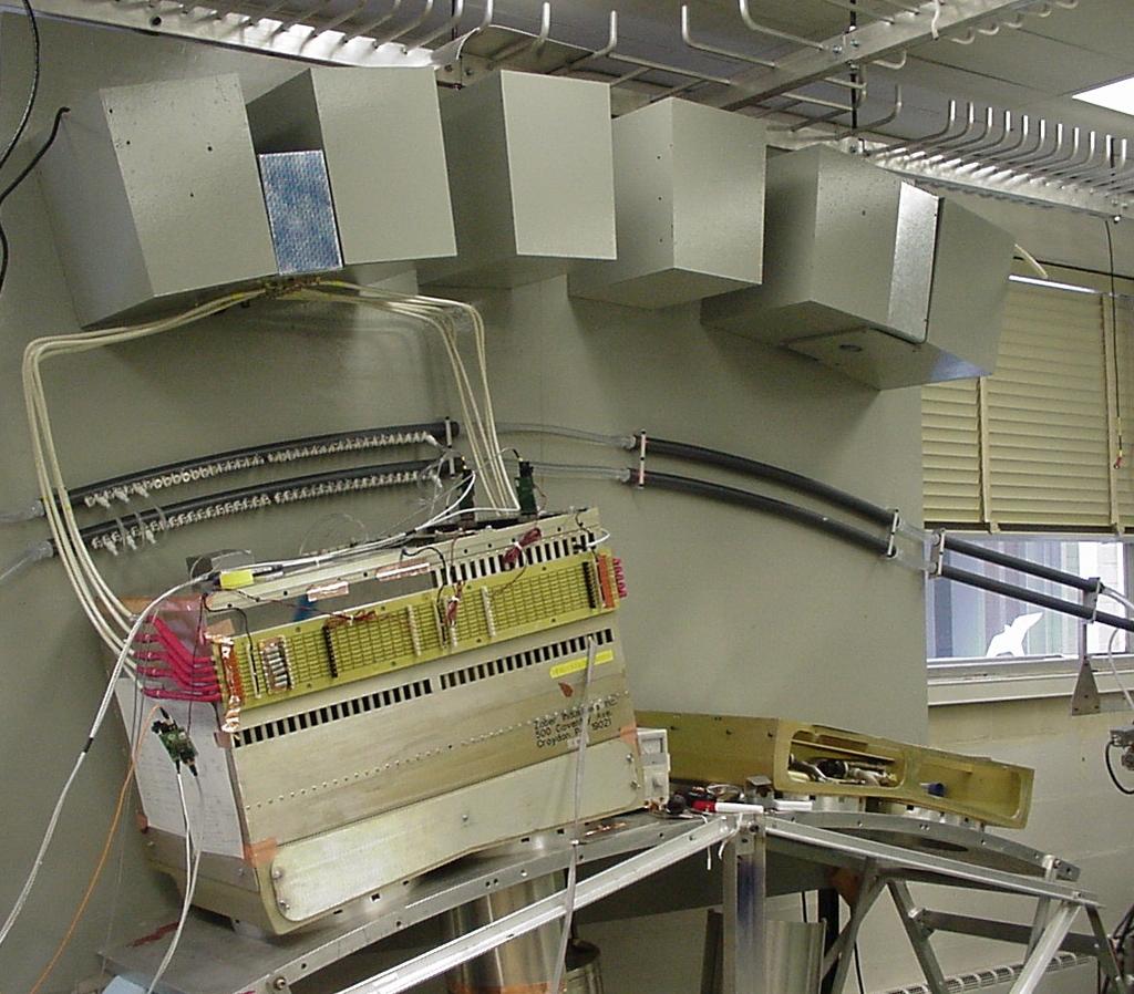
4 Prevention of EMI and isolation (1) To avoid coherent signals in group of read-out channels Noise from digital circuits generated locally on a single read-out board in the crate Cured by careful design of layout, filtering on the board, shielding of preamplifiers, minimization of digital operation on the board EM radiation surrounding the electronics and noise induced by penetration into cryostat/crates Cured by well designed Faraday cage comprised of the cryostat, the feedthrough and the crates. No electrical penetration in the cryostat except for signal and high voltage feedthrough All services (pressure and temperature) filtered in the crates and fed into the cryostat on shielded cables 17 Jun 02 LAr Electronics ASSO Review Grounding and shielding 4

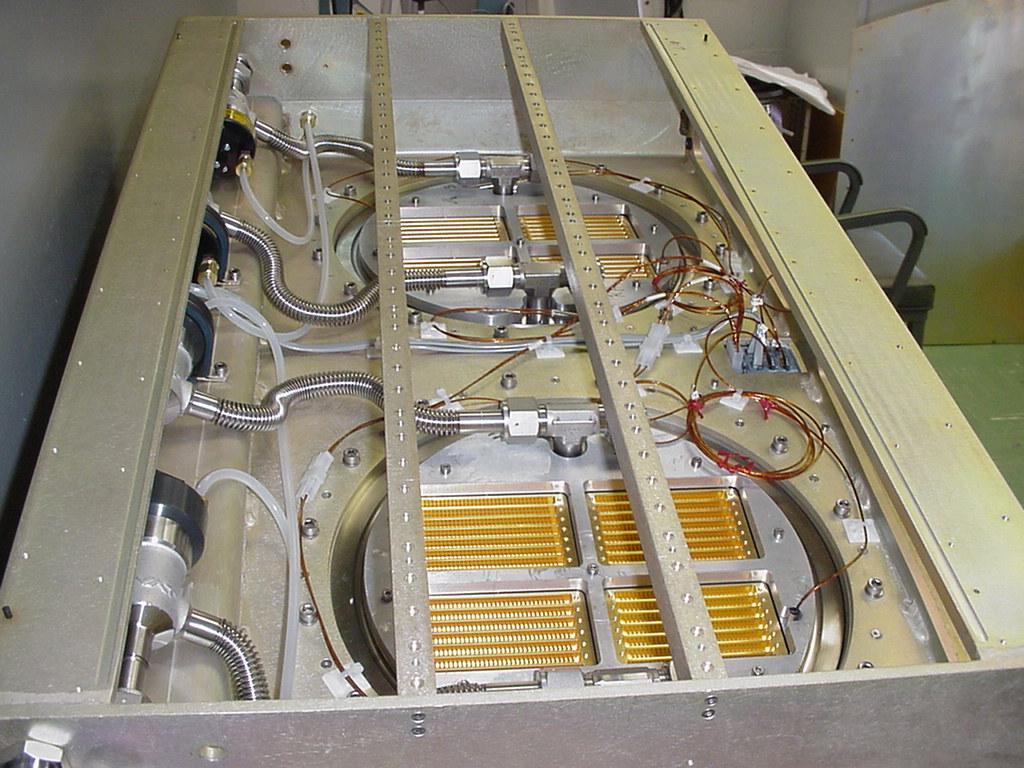
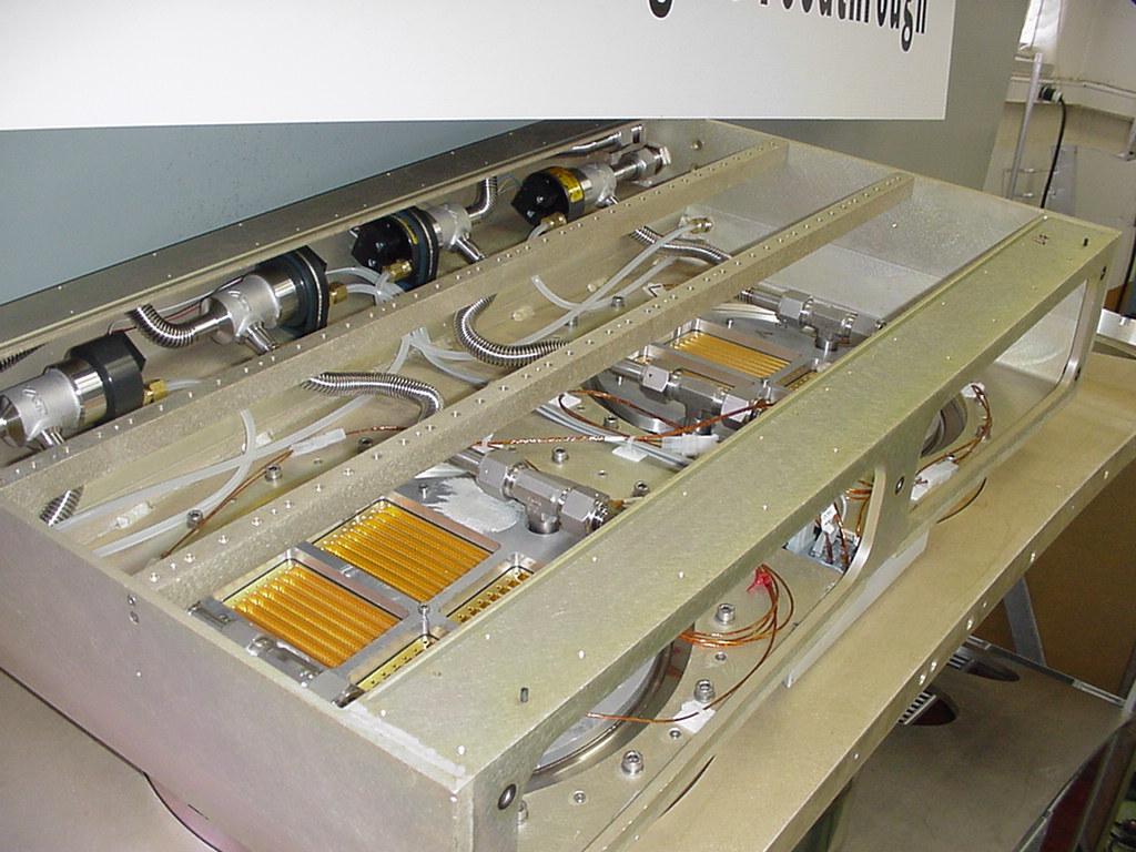
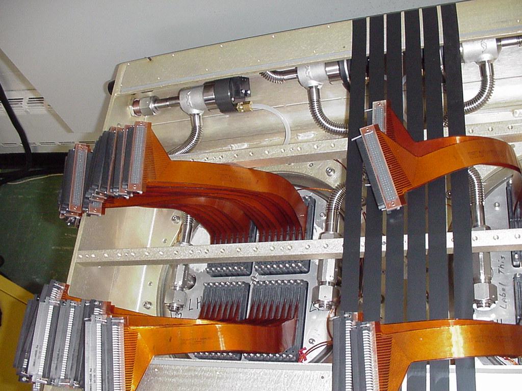
5 ATLAS LAr Calorimeter Readout Electronics Faraday Cage
6 LAr Cal. Vital lines (i.e., Potential ground loops) 1. Lar cryo lines 2. HV supplies 3. Data (opt. fibers) 4. Cooling circuit (water) FEE ~20m ~70m 5. LV supplies 6. Level 1 sums ~ channels 7. clock warm cold Accordion 8. slow control (parameter input) 9. sensors 10. solenoid cryo & supply 1., 4., 11. insulators 2., 5. floating supplies, as in Fig.2 6. differential transmission transformers (balun or signal) 7., 8. opto-couplers (or transformers) 9. insulate sensors; different techniques at various receivers 10. solenoid line to be insulated, power supply floating 12. heater insulated, capacitors to pedestal, floating supply 11. mechanical supports 12. feedthrough heater (dc) Fig. 1
7 1. Coaxial Cables Rules for Entering the Cryostat Shield connected to cryostat before penetrating Faraday cage Short connection, low inductance LAr Cryostat Performed on standard feedthroughs 2. Power Supplies Capacitors with short leads, close to cryostat low inductance connection No net DC Current in Balun to avoid saturating Ferrite (pass power and return). In magnetic field up to ~ gauss, use 3D3 type ferrite B 100 n Balun + 0 _ 100 n LAr 100 n Cryostat 10µ + 0 _ 5-10 turns on Ferrite core to floating power supply S i = cm 3. Probes, HV r to electrode LAr 100 n 100 n Capacitors with short leads, close to cryostat, low inductance connection R > 1 kw can be replaced by L > 1mH when no current flows R Fig. 3
8 Well defined safety ground Safety grounds The ground should be at USA15 To preserve from EMI the Level 1 trigger sum signals The grounding scheme should extend the faraday cage of the calorimeter to include the twisted pair cables coming from the trigger sum board. The common braid of Level 1 cables from each crate needs to be connected to the safety ground (through a ~ 2 cm braided Cu cable) Supplementary safety grounds If the analysis of the whole subsystem identifies a component which if accidentally disconnected could present hazard, then the component must have a supplementary ground connection Such a connection should be through a nonlinear element. 17 Jun 02 LAr Electronics ASSO Review Grounding and shielding 10
9 Prevention of EMI and isolation (2) Currents coming through ground loops It is the most demanding issue since it involves potential connections to equipments at various distance from the cryostat Basic design approach: isolate each cryostat with its read-out from everything else Only one location where a connection to ground will be allowed for DC and low frequencies Cryostats must be insulated at their supports and in all cryogenics lines and services Each read-out crate has to be connected to his own floating power supply The two halves of the accordion stack will be insulated from each other and from their supports and connected to the cryostat at their feedthroughs via signal cables EM end-caps will be treated in the same way 17 Jun 02 LAr Electronics ASSO Review Grounding and shielding 7
10 Safety Ground Detector PA, SCA, ADC 50 ~ 75m Signal & control > 10 µh Level 1 room Receivers DAQ Cs Floating supplies > 100 µh Safety ground
11
12 17 Jun 02 LAr Electronics ASSO Review Grounding and shielding 9
13 Low Voltage Switching Supplies and Rectifier Detector AC Neutral GFI DC 200 V- 300 V Α m Fuse ~ LV Isolated Switching Supply 3 V-12 V Shield connected only at the sending end CRYOSTAT CRATE SAFETY GROUND in Level 1 Room
14 17 Jun 02 LAr Electronics ASSO Review Grounding and shielding 11
15
16
17
18
19
20
21
22
23
24
25
26 3.1 Cryostat/solenoid insulation The general requirement is that the cryostat (both warm and cold walls) are to be isolated electrically from the solenoid and its service. Some specific steps agreed upon in discussions with the cryostat team and the solenoid team are listed here: The solenoid coil, superconducting bus lines and its associated services, i.e., the support cylinder, radiation shield panels, and cooling tubes, are to be electrically isolated from the LAr cryostat cold vessel and the warm vacuum vessel The solenoid coil will be electrically floated in the LAr cryostat, but will be grounded with a resistance of 1-10 k-ohm at the coil power supply (8,000 A). This is important in order to monitor the coil against any other conductive paths (shorts) to ground. This is also consistent with the ATLAS guidelines for all superconducting magnets. The solenoid power supply must minimize the voltage excursions with respect to ground The associated solenoid services are electrically insulated from the LAr cryostat, but they are electrically connected to the support structure for the ATLAS detector together with the solenoid chimney, the control dewar and common cryogenics ( to be provided by CERN) The (thermal) super insulation between the LAr cryostat and the solenoid must include electrical insulation. This can be achieved by adding a few layers of Kapton/mylar. Special care must be taken that there are no penetrations that allow electrical contact and violate electrical insulation. This has to be realized, while allowing sufficient passages to evacuate the solenoid vacuum space.
27 The solenoid chimney and control dewar will have to share a common vacuum with the LAr cryostat, but they must be isolated from the LAr cryostat. Consequently, an insulation flange (such as a G10 disk) is required at the nearest location (order of cm) from the bottom of the chimney ( the chimney is directly connected to the warm wall of the LAr cryostat) The solenoid services in the chimney area are electrically a part of the solenoid, as is ALL of the solenoid monitoring equipment, and thus are insulated from the cryostat Special care must be taken to minimize fluctuations in the voltage across the solenoid. At present, the expected fluctuations are: +/- 12 V in normal operation and 0 to - < 500 V in case of emergency (such as power supply switching off due to power failure or the magnet quench).
28 3.2 Insulation between the central tracker and the cryostat The general requirement is that the cryostat be isolated electrically from the central tracker and its associated services. Items of concern for isolation between these two subsystems are as follows: Tracker support rails. The tracker support rails are welded to the cryostat, and thus electrically are part of the cryostat. Consequently, the central tracker has to be insulated from the rails Tracker services supported on the cryostat inner warm wall. The tracker plans to support part of its services on the cryostat inner wall. These include cooling lines, signal and power cables. All of these have to be insulated from the cryostat inner wall Tracker services on the cryostat head-vessel. Some of the tracker services will be supported on the cryostat head-vessel. All of these services will have to be insulated from the cryostat head vessel Tracker services in the gap region. All the tracker services in the gap, including cooling pipes, cooling manifolds, and patch panels for the electrical connections, need to be supported by the cryostat and tile calorimeter. ALL are to be electrically insulated from the cryostat, as well as from the readout electronics crates that are electrically part of the cryostat Beam support. The beam is suspended from the cryostat head-vessel and the support has to be electrically insulated from the head-vessel so that there is no electrical contact between the beam pipe and the cryostat.
29 3.3 Insulation between the tile calorimeter and the cryostat The general requirement is that the cryostat has to be isolated electrically from the tile calorimeter. Insulation of support interfaces and LAr services in the space between the tile calorimeter and the cryostat concerns the following items Cryostat support legs. The cryostat support legs, that are attached to the tile by bolts, are connected to the tile calorimeter. The support stubs are connected to the cryostat. In between, there will be a thin G10 insulation that will insulate the legs electrically Cryostat wall and the tile inner surface. There is nominally 2 cm of stay-clear area between the cryostat and the tile calorimeter. So, in principle, they should not touch. It is, however, very difficult to guarantee that no loose conducting material will be dropped into that region during assembly. It is recommended that a thin layer of G10, or some other insulating material, be placed in that region to insure electrical isolation. (As some means of protection from accidental LAr spill has been suggested, the same "sheet" could also insure that no liquid drops on the tile.) The responsibility for implementation of this insulating sheet should be defined Cooling manifolds for the readout electronics. The cooling manifolds are not in electrical contact with the readout. The insulation will be made in the tubes that connect the manifold to the cooling plates attached to the front end electronics boards in the readout crates Power supplies for readout crates. The dc-dc converter solution, being investigated to locate the power supplies at the readout crates, will require that the dc-dc converter be supported in the gap and/or in the tile finger region. The dc-dc converter will have to be insulated from the tile.
30 LAr cables in the gap region. All cables that are part of the LAr subsystem will be isolated from the tile. It is also the responsibility of the LAr subsystem to insulate any cable shields from any cable trays attached to the tile calorimeter Tracker services supported on the tile calorimeter. All tracker services that have to pass through the gap will be insulated from the LAr calorimeter. These include all of the cooling pipes, cables, trays, etc. These services have to pass through the tile fingers and the isolation at that point should be defined by the tracker and the tile calorimeter subsystem.
31 3.4 Cryogenics and vacuum lines isolation The general requirement is that the cryostat has to be isolated electrically from the cryogenics and vacuum lines. The cryostat is considered as an entity, since the cold vessel is connected to the warm vessel by the very low resistance of signal returns of all vacuum cables (inside the feedthroughs) in parallel LN2 cooling lines: input and output. There are three nitrogen input and output lines per side in the barrel and two per end cap. They will be insulated by using G10 in the bayonets on the cold and warm lines. The bayonets are installed near the cryostat, about 40 cm from the outer radius of the cryostat. The design for the insulation will be done by the cryogenics team LAr fill line, LAr vacuum exhaust line and LAr dump line. The vacuum space in the LAr fill line is also used as an exhaust in case of a liquid spill to the warm vessel. Thus it has a 6 inch diameter pipe coming out on the side. The lines and the exhaust line have to be insulated.
32 Status of the policy (1) The key elements where possible are part of the design: 1. Most of the elements have been properly designed 2. Some concerns remains in the integration of LAr DCS with the overall DCS An overall review at ATLAS level is advisable 3. Interfaces with other subsystems should be reviewed The cooling system is under design with isolation The distribution of ATLAS services is not final Not all subsystems have a final design in place which can be reviewed against ATLAS grounding policy The LAr grounding policy is not formalized: Some documents exist but they are NOT easily accessible An overall EDMS document needs to be written A check list is needed to verify that the grounding policy is applied During integration and installation During commissioning 17 Jun 02 LAr Electronics ASSO Review Grounding and shielding 12
33 Example of Grounding Configuration Document Power From/To Service type Total/crate Total Actual Sizes (mm) Responsible Grounding Local Power bus 1 NA H. Takai Grounded to Crate through FEB connections Local Power cables in the Gap 10 (5/crate side) NA 15 O.D. each H. Takai Grounded to Crate Local (In the finger region) Power supply to USA1 5 Power supply to 300 Volt power Supply Power supply to ELMB Power Supply 300 V Input cable (shielded twisted pair cable) Interlock for the power supply Power supply monitoring cable NA 1 16/face 1/crate 1 (4 wires) 1 (Up to 24 wires, lines, Voltages, Current, Temperatur e) 16/face 32 total 16/face 32 total 16/face 32 total 32 total 5 O.D. each 5 O.D. each 20 O.D. each 300x300x 150 each Floating Supply, grounded to crate through low voltage cables H. Takai Shielded cable, connected to ground only at the 300V end. H. Takai To be determined H. Takai To be determined
34 Status of the policy (2) The day-by-day verification of the application of the grounding rules needs to be organized: The integration phase of the calorimeters is already started. Feedthrough, pedestals, cryogenics lines, vacuum lines etc. are being installed A supervisor of these activities needs to be nominated 17 Jun 02 LAr Electronics ASSO Review Grounding and shielding 13
Charge readout and double phase
 Charge readout and double phase Vyacheslav Galymov IPN Lyon 1 st annual meeting AIDA-2020 Liquid argon double-phase TPC Concept of double-phase LAr TPC (Not to scale) Anode 0V 2 mm Collection field 5kV/cm
Upgrade plans for the ATLAS Forward Calorimeter at the HL-LHC
 Upgrade plans for the ATLAS Forward Calorimeter at the HL-LHC John Rutherfoord on behalf of the ATLAS Liquid Argon Calorimeter Group Physics Department, University of Arizona, Tucson, AZ 85721, USA E-mail:
The ATLAS Liquid Argon Calorimeter: Construction, Integration, Commissioning Ph. Schwemling on behalf of the ATLAS LAr Group
 The ATLAS Liquid Argon Calorimeter: Construction, Integration, Commissioning Ph. Schwemling on behalf of the ATLAS LAr Group Introduction Construction, Integration and Commissioning on the Surface Installation
LHC HTS CURRENT LEADS
 CERN CH-1211 Geneva 23 Switzerland the Large Hadron Collider project LHC Project Document No. CERN Div./Group or Supplier/Contractor Document No. AT/MEL EDMS Document No. 350602 Date: 2003-07-16 Functional
CRYOGENIC CONDUCTION COOLING TEST OF REMOVABLE PANEL MOCK-UP FOR ITER CRYOSTAT THERMAL SHIELD
 CRYOGENIC CONDUCTION COOLING TEST OF REMOVABLE PANEL MOCK-UP FOR ITER CRYOSTAT THERMAL SHIELD K. Nam, a D. K. Kang, a W. Chung, a C. H. Noh, a J. Yu, b N. I. Her, b C. Hamlyn-Harris, b Y. Utin, b and K.
The Design and Fabrication of a 6 Tesla EBIT Solenoid
 LBNL-40462 SCMAG-593 The Design and Fabrication of a 6 Tesla EBIT Solenoid 1. Introduction M. A. Green a, S. M. Dardin a, R. E. Marrs b, E. Magee b, S. K. Mukhergee a a Lawrence Berkeley National Laboratory,
Microscopy Cryostat System
 OF AMERICA, INC. Microscopy Cryostat System RC102-CFM Microscopy Cryostat offers fast cooldown, high efficiency, lowest thermal drift, excellent temperature stability and ultra low vibration Optical cryostat
THE CERN CRYOGENIC TEST FACILITY FOR THE ATLAS BARREL TOROID MAGNETS
 EUROPEAN ORGANIZATION FOR NUCLEAR RESEARCH European Laboratory for Particle Physics Large Hadron Collider Project LHC Project Report 365 THE CERN CRYOGENIC TEST FACILITY FOR THE ATLAS BARREL TOROID MAGNETS
Critical parameters of
 Critical parameters of superconductors 2005-03-30 Why do this experiment? Superconductivity is a very interesting property from both commercial and basic scientific points of view. Superconductors are
Feasibility of HTS DC Cables on Board a Ship
 Feasibility of HTS DC Cables on Board a Ship K. Allweins, E. Marzahn Nexans Deutschland GmbH 10 th EPRI Superconductivity Conference Feasibility of HTS DC Cables on Board a Ship 1. Can superconducting
Cryo Mezzanine Design and Requirements. David Montanari, Aurélien Diaz, Kevin Haaf LBNF Cryostat, final design review SURF, August 2017
 Cryo Mezzanine Design and Requirements David Montanari, Aurélien Diaz, Kevin Haaf Cryostat, final design review SURF, 21-22 August 2017 Table of Content Who Am I and Where Have I Been? Proximity Cryogenics
EXEMPLAR NATIONAL CERTIFICATE (VOCATIONAL) ELECTRICAL PRINCIPLES AND PRACTICE NQF LEVEL 3 ( ) (X-Paper) 09:00 12:00
 ELECTRICAL PRINCIPLES AND PRACTICE NQF LEVEL 3 ( ) (X-Paper) 09:00 12:00") NATIONAL CERTIFICATE (VOCATIONAL) ELECTRICAL PRINCIPLES AND PRACTICE NQF LEVEL 3 2008 (12041002) (X-Paper) 09:00 12:00 EXEMPLAR This question paper consists of 7 pages. EXEMPLAR -2- NC(V) TIME: 3 HOURS
NATIONAL CERTIFICATE (VOCATIONAL) ELECTRICAL PRINCIPLES AND PRACTICE NQF LEVEL 3 2008 (12041002) (X-Paper) 09:00 12:00 EXEMPLAR This question paper consists of 7 pages. EXEMPLAR -2- NC(V) TIME: 3 HOURS
The KATRIN experiment
 The KATRIN experiment Status and SDS comissioning Philipp Chung-On Ranitzsch for the KATRIN collaboration Insitute for Nuclear Physics, Westfälische Wilhelms-Universität, Münster The KATRIN experiment
HIMARC Simulations Divergent Thinking, Convergent Engineering
 HIMARC Simulations Divergent Thinking, Convergent Engineering 8117 W. Manchester Avenue, Suite 504 Los Angeles, CA 90293 Ph: (310) 657-7992 Horizontal Superconducting Magnet, ID 1.6m 1 1 Design definition
PERFORMANCE OF THE ATLAS LIQUID ARGON FORWARD CALORIMETER IN BEAM TESTS
 1 PERFORMANCE OF THE ATLAS LIQUID ARGON FORWARD CALORIMETER IN BEAM TESTS P.KRIEGER Department of Physics, University of Toronto, Toronto, Ontario M5S 1A7, Canada E-mail: krieger@physics.utoronto.ca A
Superconducting Magnet with a Minimal Steel Yoke for the Future Circular Collider Detector
 Superconducting Magnet with a Minimal Steel Yoke for the Future Circular Collider Detector V. I. Klyukhin Skobeltsyn Institute of Nuclear Physics, Lomonosov Moscow State University, Moscow, 119992, Russia
CURRENT LEADS FOR THE LHC MAGNET SYSTEM
 EUROPEAN ORGANIZATION FOR NUCLEAR RESEARCH European Laboratory for Particle Physics Large Hadron Collider Project LHC Project Report 526 CURRENT LEADS FOR THE LHC MAGNET SYSTEM A. Ballarino Abstract The
ATLAS Hadronic Calorimeters 101
 ATLAS Hadronic Calorimeters 101 Hadronic showers ATLAS Hadronic Calorimeters Tile Calorimeter Hadronic Endcap Calorimeter Forward Calorimeter Noise and Dead Material First ATLAS Physics Meeting of the
SECTION 1 - WHAT IS A BTU METER? BTU's = Flow x ΔT Any ISTEC BTU Meter System consists of the following main components:
 SECTION 1 - WHAT IS A BTU METER? ISTEC BTU Meters measure energy usage by multiplying flow rate and temperature difference. As the water (or other liquid) passes through these lines, the multi-wing turbine
EXPERIMENT 9 Superconductivity & Ohm s Law
 Name: Date: Course number: MAKE SURE YOUR TA OR TI STAMPS EVERY PAGE BEFORE YOU START! Lab section: Partner's name(s): Grade: EXPERIMENT 9 Superconductivity & Ohm s Law 0. Pre-Laboratory Work [2 pts] 1.
PoS(TIPP2014)033. Upgrade of MEG Liquid Xenon Calorimeter. Ryu SAWADA. ICEPP, the University of Tokyo
033. Upgrade of MEG Liquid Xenon Calorimeter. Ryu SAWADA. ICEPP, the University of Tokyo") ICEPP, the University of Tokyo E-mail: sawada@icepp.s.u-tokyo.ac.jp The MEG experiment yielded the most stringent upper limit on the branching ratio of the flavorviolating muon decay µ + e + γ. A major
ICEPP, the University of Tokyo E-mail: sawada@icepp.s.u-tokyo.ac.jp The MEG experiment yielded the most stringent upper limit on the branching ratio of the flavorviolating muon decay µ + e + γ. A major
Cryogenic and Electrical Test Results of a 30 M HTS Power Cable
 Cryogenic and Electrical Test Results of a 3 M HTS Power Cable V. E. Sytnikov 1, V. S. Vysotsky 1, S. S. Fetisov 1, A. A. Nosov 1, Yu.G.Shakaryan 2, V.I.Kochkin 2, A.N.Kiselev 2, Yu.A. Terentyev 2, V.M.Patrikeev
Evaluating ATLAS LAr Front End Board Performance
 Evaluating ATLAS LAr Front End Board Performance Nevis Laboratories, Summer EU 2003 J. Gregson, Carnegie Mellon W. Pontius, Columbia ABSTACT The ATLAS experiment is scheduled to begin operation at the
Remote Display Unit. Installers Handbook Copyright 2001 AirSense Technology Ltd. LM Remote Display Unit Installers Handbook Issue 1.
 Remote Display Unit Installers Handbook Copyright 2001 AirSense Technology Ltd AirSense, ClassiFire, FastLearn PipeCAD, SenseNET, Stratos-HSSD and Stratos-Quadra are trademarks. HSSD is a Registered Trademark.
Muon reconstruction performance in ATLAS at Run-2
 2 Muon reconstruction performance in ATLAS at Run-2 Hannah Herde on behalf of the ATLAS Collaboration Brandeis University (US) E-mail: hannah.herde@cern.ch ATL-PHYS-PROC-205-2 5 October 205 The ATLAS muon
Gesellschaft für Schwerionenforschung mbh (GSI), Planckstrasse 1, D Darmstadt, Germany
, Planckstrasse 1, D Darmstadt, Germany") Proceedings of ICEC 22ICMC 2008, edited by HoMyung CHANG et al. c 2009 The Korea Institute of Applied Superconductivity and Cryogenics 9788995713822 Cold electrical connection for FAIR/ SIS100 Kauschke,
Proceedings of ICEC 22ICMC 2008, edited by HoMyung CHANG et al. c 2009 The Korea Institute of Applied Superconductivity and Cryogenics 9788995713822 Cold electrical connection for FAIR/ SIS100 Kauschke,
MODEL: WB009GMFI19HLD (120V) Wall Mount DC Inverter Fan Coil Unit 9,000 BTUH
 Wall Mount DC Inverter Fan Coil Unit 9,000 BTUH") MODEL: WB009GMFI19HLD (120V) Wall Mount DC Inverter Fan Coil Unit 9,000 BTUH No. Part Name Quantity BOM code List Price Remark 1 Panel assembly 1 201132890609 2 Air filter 2 201132890704 5 Display box
MODEL: WB009GMFI19HLD (120V) Wall Mount DC Inverter Fan Coil Unit 9,000 BTUH No. Part Name Quantity BOM code List Price Remark 1 Panel assembly 1 201132890609 2 Air filter 2 201132890704 5 Display box
Hydra Fault Current Limiting HTS Cable to be Installed in the Consolidated Edison Grid
 Hydra Fault Current Limiting HTS Cable to be Installed in the Consolidated Edison Grid J. McCall, J. Yuan, D. Folts, N. Henderson, American Superconductor D. Knoll, Southwire M. Gouge, R. Duckworth, J.
Measurements of temperature on LHC thermal models
 Measurements of temperature on LHC thermal models Christine Darve 1, Juan Casas 2, Moyses Kuchnir 1 1 : Fermi National Accelerator Laboratory, Batavia, IL, USA 2 : CERN, European Laboratory for Particle
Measurement of Tritium in Helium
 detect and identify Measurement of Tritium in Helium Dr. Alfred Klett Berthold Technologies, Bad Wildbad, Germany 22 nd Annual Air Monitoring Users Group (AMUG) Meeting Palace Station Hotel, Las Vegas,
Les Premières Données dans ATLAS et le Calorimètre à Argon Liquide
 Les Premières Données dans ATLAS et le Calorimètre à Argon Liquide Des muons cosmiques aux premières collisions S. Laplace, P. Iengo Pour le groupe ATLAS-LAPP Plan: Introduction Commissioning du calo Lar
The Cylindrical GEM detector for the KLOE-2 Inner Tracker
 The Cylindrical GEM detector for the KLOE-2 Inner Tracker G. Morello on behalf of the KLOE-2 IT group Exploring Hadron Structure with Tagged Structure Functions, January 18th, Newport News (VA) KLOE-2
Analysis of Eddy Current Distributions in the CMS Magnet Yoke during the Solenoid Discharge
 Analysis of Eddy Current Distributions in the CMS Magnet Yoke during the Solenoid Discharge V. I. Klyukhin, Member, IEEE, D. Campi, B. Curé, A. Gaddi, H. Gerwig, J. P. Grillet, A. Hervé, R. Loveless, and
Electronic calibration of the ATLAS LAr calorimeter and commissioning with cosmic muon signals
 Journal of Physics: Conference Series Electronic calibration of the ATLAS LAr calorimeter and commissioning with cosmic muon signals To cite this article: Carolina Gabaldón and the Atlas LAr Collaboration
Safety Precautions WARNING If critical situations that could lead to user s death or serious injury is assumed by mishandling of the product.
 Safety Precautions Observe the following notices to ensure personal safety or to prevent accidents. To ensure that you use this product correctly, read this User s Manual thoroughly before use. Make sure
EDIPO Test Facility User Specification
 CENTRE DE RECHERCHES EN PHYSIQUE DES PLASMAS ASSOCIATION EURATOM CONFEDERATION SUISSE CRPP-Technologie de la Fusion, CH 5232 Villigen PSI EDIPO Test Facility User Specification INT 213/15 EDIPO/SULTAN
Multiphysics Simulations for the design of a Superconducting magnet for proton therapy
 WIR SCHAFFEN WISSEN HEUTE FÜR MORGEN Paul Scherrer Institut Multiphysics Simulations for the design of a Superconducting magnet for proton therapy Ciro Calzolaio October 19, 2017 OUTLINE Superconducting
Physics 196 Final Test Point
 Physics 196 Final Test - 120 Point Name You need to complete six 5-point problems and six 10-point problems. Cross off one 5-point problem and one 10-point problem. 1. Two small silver spheres, each with
Thermal Field in a NMR Cryostat. Annunziata D Orazio Agostini Chiara Simone Fiacco
 Thermal Field in a NMR Cryostat Annunziata D Orazio Agostini Chiara Simone Fiacco Overall Objective of Research Program The main objective of the present work was to study the thermal field inside the
The Silicon-Tungsten Tracker of the DAMPE Mission
 The Silicon-Tungsten Tracker of the DAMPE Mission Philipp Azzarello, DPNC, University of Geneva for the DAMPE-STK collaboration 10th International Hiroshima Symposium on the Development and Application
DEO XGEM SHIELDING CERN / AD Bertrand LEFORT (TSO) 5/6/2012
 5/6/2012") DEO XGEM SHIELDING CERN / AD Bertrand LEFORT (TSO) blefort@cern.ch 5/6/2012 Problematic XGEM The Antiproton Decelerator (AD) delivers anti-proton beams to five different experiments. The beam is extracted
DEO XGEM SHIELDING CERN / AD Bertrand LEFORT (TSO) blefort@cern.ch 5/6/2012 Problematic XGEM The Antiproton Decelerator (AD) delivers anti-proton beams to five different experiments. The beam is extracted
System design of 60K Stirling-type co-axial pulse tube coolers for HTS RF filters
 System design of 60K Stirling-type co-axial pulse tube coolers for HTS RF filters Y. L. Ju, K. Yuan, Y. K. Hou, W. Jing, J. T. Liang and Y. Zhou Cryogenic Laboratory, Technical Institute of Physics and
He II Heat transfer through a Corrugated Tube - Test Report
 He II Heat transfer through a Corrugated Tube - Test Report Authors: Ch. Darve, Y. Huang, T. Nicol, T. Peterson Keywords: LHC inner triplet, heat exchanger, He II heat transfer, Kapitza resistance. Abstract
The Q Machine. 60 cm 198 cm Oven. Plasma. 6 cm 30 cm. 50 cm. Axial. Probe. PUMP End Plate Magnet Coil. Filament Cathode. Radial. Hot Plate.
 1 The Q Machine 60 cm 198 cm Oven 50 cm Axial Probe Plasma 6 cm 30 cm PUMP End Plate Magnet Coil Radial Probe Hot Plate Filament Cathode 2 THE Q MACHINE 1. GENERAL CHARACTERISTICS OF A Q MACHINE A Q machine
INSTITUTE OF AERONAUTICAL ENGINERING DUNDIGAL ELECTRICAL AND ELECTRONICS ENGINEERING
 INSTITUTE OF AERONAUTICAL ENGINERING DUNDIGAL ELECTRICAL AND ELECTRONICS ENGINEERING Course code : 067(07-08) Course title : High voltage engineering Course structure Lectures Tutorials Practical credits
INSTITUTE OF AERONAUTICAL ENGINEERING (Autonomous) Dundigal, Hyderabad
 Dundigal, Hyderabad") INSTITUTE OF AERONAUTICAL ENGINEERING (Autonomous) Dundigal, Hyderabad - 00 0 Department of Electrical and Electronics Engineering TUTORIAL QUESTION BANK Course Name : HIGH VOLTAGE ENGINEERING Course Code
INSTITUTE OF AERONAUTICAL ENGINEERING (Autonomous) Dundigal, Hyderabad - 00 0 Department of Electrical and Electronics Engineering TUTORIAL QUESTION BANK Course Name : HIGH VOLTAGE ENGINEERING Course Code
RC Circuit (Power amplifier, Voltage Sensor)
") Object: RC Circuit (Power amplifier, Voltage Sensor) To investigate how the voltage across a capacitor varies as it charges and to find its capacitive time constant. Apparatus: Science Workshop, Power
Object: RC Circuit (Power amplifier, Voltage Sensor) To investigate how the voltage across a capacitor varies as it charges and to find its capacitive time constant. Apparatus: Science Workshop, Power
Electrostatics. Apparatus:
 Electrostatics Object: This experiment allows you to investigate the production of static charge, conservation of charge and the behavior of charges on conductors, which are interacting via Coulomb forces.
ATLAS Tile Calorimeter Calibration and Monitoring Systems
 ATLAS Calibration and Monitoring Systems June 19 th -23 rd, 217 Arely Cortes-Gonzalez (CERN) On behalf of the ATLAS Collaboration ATLAS Detector Trigger Hardware based L1 ~1kHz Software based HLT ~1kHz
PHY 101 Practice Exam III Monday, November 27, 2:15-3:35PM
 1 PHY 101 Practice Exam III Monday, November 27, 2:15-3:35PM Please be sure to show your work where it is requested. If no work is shown where it is requested, you will not receive any points. Partial
Physics 2220 Fall 2010 George Williams THIRD MIDTERM - REVIEW PROBLEMS
 Physics 2220 Fall 2010 George Williams THIRD MIDTERM - REVIEW PROBLEMS Solution sets are available on the course web site. A data sheet is provided. Problems marked by "*" do not have solutions. 1. An
PHY3901 PHY3905. Hall effect and semiconductors Laboratory protocol
 PHY3901 PHY3905 Hall effect and semiconductors Laboratory protocol PHY3901 PHY3905 Hall effect and semiconductors Laboratory protocol Objectives Observe and qualitatively understand the phenomenon of transverse
ELECTRO MAGNETIC FIELDS
 SET - 1 1. a) State and explain Gauss law in differential form and also list the limitations of Guess law. b) A square sheet defined by -2 x 2m, -2 y 2m lies in the = -2m plane. The charge density on the
Helium two-phase flow in a thermosiphon open loop
 Presented at the COMSOL Conference 2009 Milan COMSOL Conference 2009 Milan October 14-16 2009 Helium two-phase flow in a thermosiphon open loop Florian Visentin, Bertrand Baudouy CEA Saclay Accelerator,
STATUS OF ATLAS TILE CALORIMETER AND STUDY OF MUON INTERACTIONS. 1 Brief Description of the ATLAS Tile Calorimeter
 STATUS OF ATLAS TILE CALORIMETER AND STUDY OF MUON INTERACTIONS L. E. PRICE Bldg 362, Argonne National Laboratory, Argonne, IL 60439, USA E-mail: lprice@anl.gov (For the ATLAS Tile Calorimeter Collaboration)
Alternating Current (AC): Alternating Current is electric current that reverses directions at regular intervals.
: Alternating Current is electric current that reverses directions at regular intervals.") Glossary Alternating Current (AC): Alternating Current is electric current that reverses directions at regular intervals. American National Standards Institute (ANSI): American National Standards Institute
Glossary Alternating Current (AC): Alternating Current is electric current that reverses directions at regular intervals. American National Standards Institute (ANSI): American National Standards Institute
PHYS320 ilab (O) Experiment 2 Instructions Conservation of Energy: The Electrical Equivalent of Heat
 Experiment 2 Instructions Conservation of Energy: The Electrical Equivalent of Heat") PHYS320 ilab (O) Experiment 2 Instructions Conservation of Energy: The Electrical Equivalent of Heat Objective: The purpose of this activity is to determine whether the energy dissipated by a heating resistor
PHYS320 ilab (O) Experiment 2 Instructions Conservation of Energy: The Electrical Equivalent of Heat Objective: The purpose of this activity is to determine whether the energy dissipated by a heating resistor
Flow-meter calibrations for the ID of the ATLAS Experiment
 Flow-meter calibrations for the ID of the ATLAS Experiment Supervisors: Stephen McMahon and Vaclav Vacek Collaborators: R. Marek, M. Doubek and M. Vítek 31.1.29 CTU IN PRAGUE ATLAS SCT Abstract This report
Calorimetry in particle physics experiments
 Calorimetry in particle physics experiments Unit N. 9 The NA48 ECAL example (LKR) Roberta Arcidiacono R. Arcidiacono Calorimetry 1 Lecture overview The requirements Detector layout & construction Readout
PREX Simulation Update
 PREX Simulation Update Rakitha Beminiwattha Syracuse University rakithab@jlab.org 1 Outline PREX-II Collimator Plastic Shielding for Neutrons PREX-II Background Radiation Effects of Septum Magnet Fringe
Introduction to Blackbody Sources
 Introduction to s This section contains dedicated blackbody sources for low uncertainty calibration of infrared thermometers. A range of portable primary blackbody sources combine high emissivity with
Instruction Manual for EP-20 e/m of the Electron Apparatus
 Instruction Manual for EP-20 e/m of the Electron Apparatus Introduction This self-contained apparatus is designed for the measurement of e/m of the electron by observing the radius of the circular path
Examination Heat Transfer
 Examination Heat Transfer code: 4B680 date: 17 january 2006 time: 14.00-17.00 hours NOTE: There are 4 questions in total. The first one consists of independent sub-questions. If necessary, guide numbers
Commissioning of the ATLAS LAr Calorimeter
 Commissioning of the ATLAS LAr Calorimeter S. Laplace (CNRS/LAPP) on behalf of the ATLAS Liquid Argon Calorimeter Group Outline: ATLAS in-situ commissioning steps Introduction to the ATLAS LAr Calorimeter
Commissioning testing of a 1 MVA Superconducting transformer featuring 2G HTS Roebel cable
 Commissioning testing of a 1 MVA Superconducting transformer featuring 2G HTS Roebel cable Glasson N, Staines M, Allpress N, Badcock R 10:45 2M-LS-O2 OUTLINE Introduction Electrical Design Specifications
PASSIVE COMPONENTS FOR A 3D ENVIRONMENT
 PASSIVE COMPONENTS FOR A 3D ENVIRONMENT Prof. Braham Ferreira Dr. I. Josifovic TU Delft Delft, Netherlands Commercial Power Electronics - drawbacks 2D layout + Non-uniform height + Poor thermal properties
VX25 Enclosure System. Technical documentation PE conductor connection, current carrying capacity
 VX Enclosure System Technical documentation PE conductor connection, current carrying capacity Enclosure system VX Contents Contents. General remarks. Introduction. Notes on the design of the earthing
Status of the physics validation studies using Geant4 in ATLAS
 Status of the physics validation studies using Geant4 in ATLAS On behalf of the ATLAS Geant4 Validation Team A.Dell Acqua CERN EP/SFT, Geneva, CH dellacqu@mail.cern.ch The new simulation for the ATLAS
Demonstration 1: Faraday Ice Pail and Charge Production
 Osservazioni e Misure Lezioni I e II Laboratorio di Elettromagnetismo Demonstration 1: Faraday Ice Pail and Charge Production Equipment Required: Electrometer (ES-9078) Charge Producers (ES-9057B) Earth
ORTEC. SLP Series Silicon Lithium-Drifted Planar Low-Energy X Ray Detector Product Configuration Guide
 ORTEC SLP Series Silicon Lithium-Drifted Planar Low-Energy Ray Detector For x-ray spectroscopy with a nuclear accelerator, radioactive source, or x-ray tube. Premium performance spectroscopy from 1 kev
Electrization of the superconductive windings and tori and the new type of contact potential difference
 Electrization of the superconductive windings and tori and the new type of contact potential difference F.F. Mende Abstract In the article is examined new physical phenomenon the electrocurent contact
Cryostat Assembly. 17 September Martin Nordby, Rafe Schindler, Gary Guiffre, Rick Van Berg
 Cryostat Assembly 17 September 2008 Martin Nordby, Rafe Schindler, Gary Guiffre, Rick Van Berg General Cryostat section views Contents Raft Tower load transfer process Integration fixturing Back end cable
Electrostatics x C.
 Electrostatics Theory The study of charges at rest is called electrostatics. You are no doubt aware that objects can acquire excess amounts of charge by contact. What happens when you walk across a carpeted
5 Hadronic calorimetry
 5 Hadronic calorimetry The hadronic calorimetry of ATLAS (a view of which is presented in Figure -iii) consists of three main devices. In the barrel region ( η
Latest Status of High Temperature Superconducting Cable Projects
 Latest Status of High Temperature Superconducting Cable Projects Y.Ashibe, H.Yumura, M.Watanabe, H.Takigawa, H.Ito, M.Ohya, T.Masuda and M.Hirose Sumitomo Electric Industries, Ltd.Osaka,554-0024 Japan
Ch. 3. Pulsed and Water Cooled Magnets. T. J. Dolan. Magnetic field calculations
 Ch. 3. Pulsed and Water Cooled Magnets T. J. Dolan Magnetic field calculations Coil forces RLC circuit equations Distribution of J and B Energy storage Switching and transmission Magnetic flux compression
Lawrence Berkeley National Laboratory Lawrence Berkeley National Laboratory
 Lawrence Berkeley National Laboratory Lawrence Berkeley National Laboratory Title The Mechanical and Thermal Design for the MICE Focusing Solenoid Magnet System Permalink https://escholarship.org/uc/item/7652n8md
The development of a Roebel cable based 1 MVA HTS transformer
 The development of a Roebel cable based 1 MVA HTS transformer Neil Glasson 11 October 2011 Mike Staines 1, Mohinder Pannu 2, N. J. Long 1, Rod Badcock 1, Nathan Allpress 1, Logan Ward 1 1 Industrial Research
Solution for Fq. A. up B. down C. east D. west E. south
 Solution for Fq A proton traveling due north enters a region that contains both a magnetic field and an electric field. The electric field lines point due west. It is observed that the proton continues
Lab 1: Determination of e/m for the electron
 Lab 1: Determination of e/m for the electron Background Reading: Tipler, Llewellyn pp. 125 130; this covers the original method of Thomson which is somewhat different from that used in this experiment
SPIRAL 2 Commissioning Status
 SPIRAL 2 Commissioning Status Jean-Michel Lagniel (GANIL) for the SPIRAL 2 Team With thanks to the SPIRAL 2 team Page 1 Menu 1- SPIRAL 2 facility (Phase 1) presentation 2- Injector commisionning (Sources
Agenda for Today. Elements of Physics II. Lenz Law. Emf opposes change in flux Faraday s Law Induced EMF in a conducting loop
 Lenz Law Physics 132: Lecture e 22 Elements of Physics II Agenda for Today Emf opposes change in flux Faraday s Law Induced EMF in a conducting loop Physics 201: Lecture 1, Pg 1 Lenz s Law Physics 201:
THE CHARGE-TO-MASS RATIO OF THE ELECTRON (e/m)
") THE CHARGE-TO-MASS RATIO OF THE ELECTRON (e/m) INTRODUCTION In this experiment you will be measuring the charge to mass ratio, e/m, of the electron. The h/e apparatus consists of an electron gun, a helium
THE CHARGE-TO-MASS RATIO OF THE ELECTRON (e/m) INTRODUCTION In this experiment you will be measuring the charge to mass ratio, e/m, of the electron. The h/e apparatus consists of an electron gun, a helium
user's manual nx frequency converters resolver option board opt-bc
 user's manual nx frequency converters resolver option board opt-bc INDEX Document code: ud01039d Date: 18.2.2011 1. Resolver option board OPT-BC... 3 1.1 Resolver basics... 3 1.2 Resolver board features...
Code No: RR Set No. 1
 Code No: RR410209 Set No. 1 1. What are the gases mainly used in insulating medium at high pressures? Which is more suitable? Why? What about its dielectric strength? Explain. [16] 2. (a) Define time lags
THE DIMENSIONING OF ELECTRICAL CONDUCTORS FOR USE IN "PANEL BOARDS" ADDRESSED TO HAZARDOUS AREAS - PART THREE
 July 04 THE DIMENSIONING OF ELECTRICAL CONDUCTORS FOR USE IN "PANEL BOARDS" ADDRESSED TO HAZARDOUS AREAS - PART THREE In this third part. we want to speak about how important is the correct sizing of the
D- Charge Exchange Ionizer for the JINR Polarized Ion Source POLARIS
 D- Charge Exchange Ionizer for the JINR Polarized Ion Source POLARIS V.P. Ershov, V.V.Fimushkin, G.I.Gai, L.V.Kutuzova, Yu.K.Pilipenko, V.P.Vadeev, A.I.Valevich Λ and A.S. Belov Λ Joint Institute for Nuclear
Report CERN-ACC Considerations for a QD0 with Hybrid Technology in ILC
 CERN-ACC-2014-0197 Michele.Modena@cern.ch Report Considerations for a QD0 with Hybrid Technology in ILC M. Modena, A. Aloev #, H. Garcia, L. Gatignon, R. Tomas CERN, Geneva, Switzerland Keywords: ILC Abstract
Status & Plans for the TRIUMF ISAC Facility
 Status & Plans for the TRIUMF ISAC Facility P.W. Schmor APAC 07, Jan 29-Feb 2 Indore, India TRIUMF ISAC Schematic Layout of TRIUMF/ISAC with H- Driver, ISOL Production & Post Accelerators ISAC-II High
PHY 1214 General Physics II
 PHY 1214 General Physics II Lecture 20 Magnetic Flux and Faraday s Law July 6-7, 2005 Weldon J. Wilson Professor of Physics & Engineering Howell Hall 221H wwilson@ucok.edu Lecture Schedule (Weeks 4-6)
Determining Characteristic Impedance and Velocity of Propagation by Measuring the Distributed Capacitance and Inductance of a Line
 Exercise 2-1 Determining Characteristic Impedance and Velocity EXERCISE OBJECTIVES Upon completion of this exercise, you will know how to measure the distributed capacitance and distributed inductance
High-temperature superconducting magnet for use in Saturated core FCL
 High-temperature superconducting magnet for use in Saturated core FCL Z Bar-Haim 1, A Friedman 1,, Y Wolfus, V Rozenshtein 1, F Kopansky, Z Ron 1, E Harel 1, N Pundak 1 and Y Yeshurun 1Ricor-Cryogenic
Silicon Detectors. Particle Physics
 Mitglied der Helmholtz-Gemeinschaft Silicon Detectors for Particle Physics 9. August 2012 Ralf Schleichert, Institut für Kernphysik Outline Different Cameras Silicon Detectors Taking Pictures in Particle
Magnetic Field measurements with Csmagnetometers
 Magnetic Field measurements with Csmagnetometers in nedm project at PSI A.Pazgalev *, M.Cvijovic, P.Knowles, and A.Weis FRAP, Fribourg University, CH-1700 FRIOURG * on leave from IOFFE Phys.-Tech. Instit.,
Experimental Investigation of High-Temperature Superconducting Magnet for Maglev
 Experimental Investigation of High-Temperature Superconducting Magnet for Maglev Ken Nagashima, Masafumi Ogata, Katsutoshi Mizuno, Yuuki Arai, Hitoshi Hasegawa, Takashi Sasakawa Railway Technical Research
To be published in the Proceedings of ICEC-22, Seoul Korea, July 2008 MICE Note 232 1
 To be published in the Proceedings of ICEC-22, Seoul Korea, 21-25 July 2008 MICE Note 232 1 AC Loss Analysis on the Superconducting Coupling in MICE H. Wu, L. Wang, M. A. Green*, L. K. Li, F. Y. Xu, X.
Flow Measurement. SITRANS F M System information SITRANS F M electromagnetic flowmeters. 4/22 Siemens FI
 Function All are based on Faraday s law of induction: U M = B v d k U M = Measured voltage induced in the medium perpendicular to the magnetic field and the flow direction. The voltage is tapped at two
PRACTICE EXAM 2 for Midterm 2
 PRACTICE EXAM 2 for Midterm 2 Multiple Choice Questions 1) In the circuit shown in the figure, all the lightbulbs are identical. Which of the following is the correct ranking of the brightness of the bulbs?
Fault Current Limiter Based on Coated Conductor
 superior performance. powerful technology. Fault Current Limiter Based on Coated Conductor Juan-Carlos H. Llambes, Ph.D. SFCL Program Manager / Senior High Voltage Engineer University of Houston: V. Selvamanickam,
Status and Progress of a Fault Current Limiting HTS Cable To Be Installed In The Consolidated Edison Grid
 Status and Progress of a Fault Current Limiting HTS Cable To Be Installed In The Consolidated Edison Grid J. Yuan, J. Maguire, D. Folts, N. Henderson, American Superconductor D. Knoll, Southwire M. Gouge,