Lectures on Applied Reactor Technology and Nuclear Power Safety. Lecture No 6
|
|
|
- Aubrie Chapman
- 5 years ago
- Views:
Transcription
1 Lectures on Nuclear Power Safety Lecture No 6 Title: Introduction to Thermal-Hydraulic Analysis of Nuclear Reactor Cores Department of Energy Technology KTH Spring 2005 Slide No 1
2 Outline of the Lecture Thermal Issues in Nuclear Reactor Cores Power Generation in Nuclear Reactor Cores Principle of Fluid-Flow and Heat Transfer Slide No 2
3 Thermal Issues in Nuclear Reactors (1) Overview of Main Reactor Components in Light Water Reactors (LWR) Reactor pressure vessel: In Pressurized Water Reactors (PWR) In Boiling Water Reactors (BWR) Fuel Assemblies In BWR In PWR Specific thermal issues in LWRs Slide No 3
 Slide")
4 Schematic of Nuclear Power Plant (PWR) Slide No 4
 Slide")
5 Schematic of Nuclear Power Plant (BWR) Slide No 5
 Slide")
6 Nuclear Reactor Vessel (PWR) Slide No 6
 Slide")
7 Nuclear Reactor Vessel (BWR) Slide No 7
 Slide No")
8 Fuel Assemblies (PWR) Slide No 8

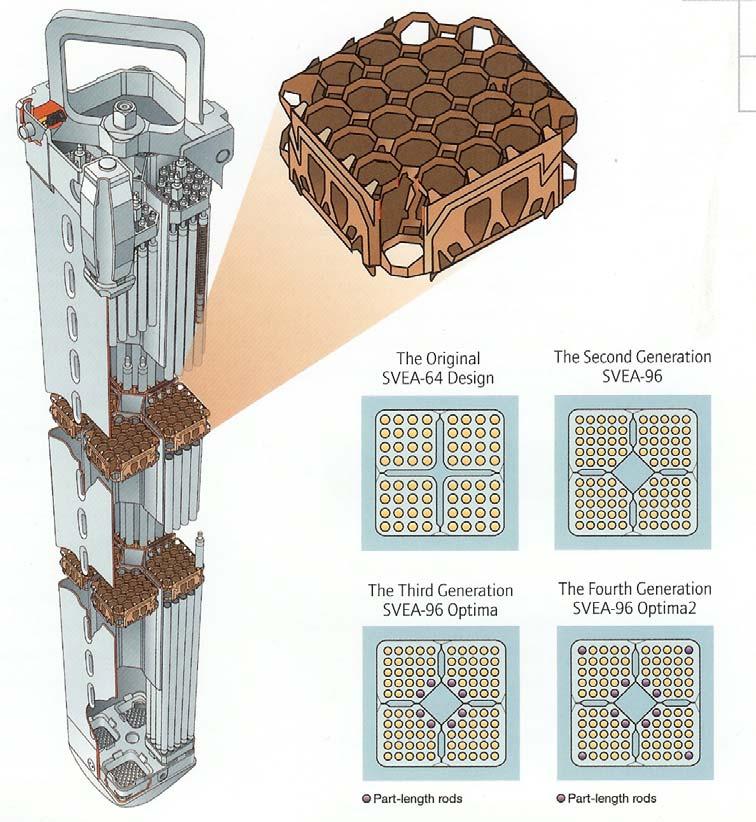
9 Fuel Assemblies (BWR) Slide No 9
10 Energy Cycles in LWRs Fission-product energy in fuel Conduction through fuel Transfer across fuel-clad gas gap Forced convection in coolant in fuel assemblies Transfer from clad surface to coolant Conduction across clad Steam generation due to boiling Steam separation Slide No 10
11 Specific Thermal Issues in LWRs (1) There are several existing reactor concepts in which heat transfer solutions depend on particular design concepts and the choice of coolant Although each reactor design has its own specific thermal problems, the solution of these problems can be approached in standard engineering manners that involve the fluid flow and heat transfer analysis The effort to integrate the heat transfer and fluid mechanics principles to accomplish the desired rate of heat removal from the reactor fuel is termed as the thermal-hydraulic design of a nuclear reactor Slide No 11
12 Specific Thermal Issues in LWRs (2) Important difference between nuclear power plants and conventional power plants: in conventional power plants the temperature is limited to that resulting from combustion of coal, oil or gas temperature can increase continuously in a nuclear reactor when the rate of heat removal is less than the rate of heat generation Such situation could lead to the core damage Slide No 12
13 Specific Thermal Issues in LWRs (3) For a given reactor design, the maximum operating power is limited by some temperature in the system There are several possible factors that will set the limit temperature (and thus the reactor power): material changes of some construction material in the reactor allowable thermal stresses or influence of temperature on corrosion Thus the maximum temperature in a nuclear reactor core must be definitely established under normal reactor operation and this is the goal of the thermal-hydraulic design and analysis of nuclear reactor cores Slide No 13
14 Specific Thermal Issues in LWRs (4) In nuclear reactors the construction materials must be chosen not only on the basis of the thermo-mechanical performance, but also (and often exclusively) on the basis of the nuclear properties Beryllium metal, for example, is an excellent material for use as moderator and reflector, but it is relatively brittle Austenitic stainless steels are used as the cladding for fast reactor fuels, but they tend to swell as a result of exposure at high temperatures to fast neutrons Slide No 14
15 Specific Thermal Issues in LWRs (4) Another peculiarity (and factor that adds problem) of nuclear reactors is that the power densities (e.g. power generated per unit volume) are very high This is required by economical considerations That leads to power densities of approximately 100 MWt/m 3 in PWRs and 55 MWt/m 3 in BWRs A typical sodium-cooled commercial fast breeder reactor has a power density as high as 500 MWt/m 3 In conventional power plants is of the order of 10 MWt/m 3. Slide No 15

16 Power Generation in Nuclear Reactor Cores (1) Chain reaction is the primary source of energy in nuclear reactors Slide No 16
17 Power Generation in Nuclear Reactor Cores (2) The energy released in nuclear fission reaction is distributed among a variety of reaction products characterized by different range and time delays In thermal design, the energy deposition distributed over the coolant and structural materials is frequently reassigned to the fuel in order to simplify the thermal analysis of the core Slide No 17
18 Power Generation in Nuclear Reactor Cores (3) The volumetric fission heat source in the core can be found as, q ( r) = i () ( i) r deσ ( E)( φ r E) ( i) w f N i f, 0 w f (i) here is the recoverable energy released per fission event for i-th fissionable material Slide No 18
19 Power Generation in Nuclear Reactor Cores (4) The simplest model of fission heat distribution would correspond to a bare, homogeneous core One-group flux distribution for such geometry is given as, ν 0r πz φ( r, z) = J 0 ~ cos ~ R H here R ~ and H ~ are effective core dimensions that include extrapolation lengths as well as an adjustment to account for a reflected core Slide No 19
20 Power Generation in Nuclear Reactor Cores (5) For a fuel rod located at r = r f distance from the centerline of the core, the volumetric fission heat source becomes a function of the axial coordinate, z, only: q ( z) = w 2.405r ~ R π z cos H f f Σ f φ0 J 0 ~ Slide No 20
21 Power Generation in Nuclear Reactor Cores (6) There are numerous factors that perturb the power distribution of the reactor core, and the above equation will not be valid For example fuel is usually not loaded with uniform enrichment At the beginning of core life, higher enrichment fuel is loaded toward the edge of the core in order to flatten the power distribution Other factors include the influence of the control rods and variation of the coolant density Slide No 21
22 Power Generation in Nuclear Reactor Cores (7) All these power perturbations will cause a corresponding variation of temperature distribution in the core A usual technique to take care of these variations is to estimate the local working conditions (power level, coolant flow, etc) which are the closest to the thermal limitations Such part of the core is called hot channel and the working conditions are related with so-called hot channel factors Slide No 22
23 Power Generation in Nuclear Reactor Cores (8) One common approach to define hot channel is to choose the channel where the core heat flux and the coolant enthalpy rise is a maximum Working conditions in the hot channel are defined by several ratios of local conditions to core-averaged conditions These ratios, termed the hot channel factors or power peaking factors will be considered in more detail in coming lectures However, it can be mentioned already here that the basic initial plant thermal design relay on these factors Slide No 23
24 Principles of Fluid-Flow and Heat Transfer Heat Conduction Laminar and Turbulent Flows Solid-Fluid Heat Transfer for Single-Phase Flows Slide No 24
25 Heat Conduction (1) Heat conduction refers to the transfer of heat by means of the molecular interactions The central role in heat conduction plays the Fourier law: ( r, t ) = T ( r, t) q λ ( ) here q r,t is the heat flux vector at location r and time t, T(r,t) is the local temperature and λ is the thermal conductivity Slide No 25
26 Heat Conduction (2) A non-stationary heat balance in a finite volume dv is as follows: z q z +dq z q x q y q x +dq x q y +dq y y x q z q dydzdt + q dxdzdt + q dxdydt + q dxdydzdt x y z ( q + dq ) dydzdt ( q + dq ) dxdzdt ( q + dq ) dxdydt = ρc dtdxdydz x x y y z z p Slide No 26
27 Heat Conduction (3) Equation can be simplified as q dxdydzdt dq dydzdt x dq dxdzdt y dq dxdydt z = ρc p dtdxdydz and dividing by dxdydzdt q q x y q z q = ρc x y z or p T t ρc p T t = q q ρ c p T t = q + λ T Slide No 27
28 Heat Conduction (4) In general case, when solid properties are time-andspace dependent, the conduction equation can be written as, t [ ρ( r, t) c( r, t) T ( r, t) ] [ λ( r, t) T ( r, t) ] = q ( r, t) This equation can be solved if proper initial and boundary conditions are specified: Initial conditions specify the temperature distribution at initial time, typically at t = 0, e.g. T(r,0) = f(r) is a given function Boundary conditions describe the temperature behaviour at the boundary. They are of four different kinds, described below Slide No 28
29 Heat Conduction (5) Boundary conditions: Of the first kind (Dirichlet b.c.) when temperature value is given at the boundary, e.g., T ( r, t) = ϕ( r, t) r r= B Of the second kind (Neuman b.c.) when the heat flux at the boundary is given, e.g., q ( r t) ( r, t) T, λ = φ( r, t) r= rb n Of the third kind (Newton b.c.) with convective heat transfer T λ n ( r, t) r= r B = r= r B [ ( ) ( ) ] r, t T r, t * h T r= r B f r= r B Slide No 29
30 Heat Conduction (6) Boundary conditions (cont ed) Of the fourth kind when two solids are in contact, T Example: ( r t) = T ( r, t) T and λ ( r, t) T ( r, t) 1 2 1, = r 2 1 λ2 = rb r= rb n r= r B Steady-state heat conduction through an infinite cylindrical wall. Figure below shows the geometry and the boundary conditions of the case considered in the present example. n r= r B q T f r 1 r 2 r Slide No 30
31 Heat Conduction (7) Conduction equation becomes: d dr r dt dr = 0 T = C ln r + D And the boundary conditions give the constants C and D: dt dt λ = q, λ = h T r= r dr r= r dr r= r 1 2 ( Tf ) 2 C λ r 1 C λ r 2 = = q r1 q, C = λ h ( C ln r + D T ) 2 f, D C = λ hr 2 C ln r 2 + T f D = T f + q r1 λ λ hr2 + ln r 2 Slide No 31
32 Heat Conduction (8) The solution can be thus written as: q r q r q r q r r q r1 T = ln r + ln r2 + + T f = ln + + T λ λ hr λ r hr 2 2 f Slide No 32
33 Laminar and Turbulent Flows (1) To describe the fluid motion, the basic laws for conservation of mass, momentum and energy are invoked For incompressible (e.g. with constant density) flows the equations are as follows: Mass Momentym Energy div( v) = 0 Dv ρ Dt DH ρ Dt = ρg + τ p Dp = + div T Dt ( λ ) + Φ Slide No 33
34 Laminar and Turbulent Flows (2) The majority of fluids obey the Newton s eqation that relates the stress tensor in terms of the strain tensor. Such fluids are termed as the Newtonian fluids τ = µ [ ( ) ] T v + v For a one-dimensional laminar flow (e.g. in pipes), the stress-strain relation becomes: dr dv z τ = µ Slide No 34
35 Laminar and Turbulent Flows (3) Assuming laminar, stationary, adiabatic flow of a Newtonian fluid in a vertical tube, the conservation equations reduce to: 0 = p + ρg + µ 2 v In cylindrical coordinates we have, 2 = 1 r d dr r d dr Slide No 35
36 Laminar and Turbulent Flows (4) Since the velocity in such a flow has only a one component, v z, the momentum conservation equation simplifies to: p ρ g µ which can be solved as: Π = 1 r d dr r dv dr z d dr r 2 2 dvz dvz Πr dvz Πr C Πr = Πr r = + C = + vz = + C ln r + dr dr 2 dr 2 r 4 D D = 2 2 ΠR ΠR r v z = R 2 Slide No 36
37 Laminar and Turbulent Flows (5) The average velocity in the tube can be found as U 1 πr 2 0 R v z ( r) 2πrdr = Π R 8µ 2 And the wall shear stress can be calculated as τ w = dvz ΠR τ ( r) µ = = r= R dr 2 r= R 4µ U R Slide No 37
38 Laminar and Turbulent Flows (6) There are two definitions commonly used in the literature to define friction factors: Darcy friction factor Fanning friction factor λ 4τ 2 ρu w 2 C f τ w = ρ U λ 4 Slide No 38
39 Laminar and Turbulent Flows (7) For laminar flow: λ 64 Re = C f = 16 Re Where Re is the Reynolds number Re = ρud µ Slide No 39
40 Laminar and Turbulent Flows (8) For turbulent flows in smooth tubes, Blasius proposed the following correlation: C f = Re For commercial tubes, which have wall roughness k, Colebrook devised the following formula 1 = 2.0log λ 10 k D Re λ Slide No 40
41 Laminar and Turbulent Flows (9) Colebrook s formula is implicit: this annoyance can be avoided by instead using the Haaland formula: 1 = 1.8log λ 10 k D Re Slide No 41
42 Solid-Fluid Heat Transfer for Single-Phase Flows (1) Heat transfer from the clad surface to the single-phase coolant is often described by the Newton s law of cooling: q = h ( ) T w T f Here h is the heat transfer coefficient. It can be found from the Dittus-Boelter correlation: Nu = 0.023Re 0.8 Pr 0.33 Nu = hd λ Pr = c p µ λ Slide No 42
43 Exercises (1) Exercise 13. A cylindrical core has the extrapolated height and extrapolated radius equal to 3.8 m and 3.2 m, respectively. Calculate the volumetric heat source ratio between the point located in the middle of the central fuel assembly and the point located in a fuel assembly with a distance r f = 1.5 m from the core center and at z = 2.5 m from the inlet of the assembly. Slide No 43
44 Exercises (2) Exercise 14. A cylindrical wall with the internal diameter equal to 8 mm and thickness 0.5 mm is heated on the internal surface with a heat flux equal to 1 MW m -2. Calculate the temperature difference between the inner and the outer surface of the wall, assuming that the thermal conductivity of the wall material is equal to 16 W m -1 K -1. What will be the heat flux on the outer surface of the wall? Slide No 44
45 Exercises (3) Exercise 15. In a horizontal pipe with an internal diameter equal to 10 mm flows water. Calculate the wall shear stress change when mass flux of water increases from 50 to 2000 kg m -2 s -1. Assume that the water density and the dynamic viscosity are constant and equal to 740 kg m -3 and 1.0x10⁻⁴ Pa s, respectively. Slide No 45
46 Exercises (4) Exercise 16. For geometry as in the picture and given Q = 2.5 x 10 4 W, wall conductivity coefficient λ 1 = 16 Wm -1 K -1, liquid temperature T L = 323 C, and mass flow rate G = 2000 kg m -2 s -1 : 1. Write shell balance for energy diffusion in the cylindrical solid, 2. state proper boundary conditions (boundary value problem), 3. calculate temperature distribution in the cylindrical solid, Obtain the heat transfer coefficient from the Dittus-Boelter correlation. Conductivity, heat capacity and dynamic viscosity of water are constant values: λ 2 = 0.5 Wm - 1 K -1, c p = 6 x 10 3 Jkg -1 K -1, µ = 8.5 x 10⁻⁵ r 3 =18 Q T L L = 1000 kgm -1 s -1. r 1 = 8 r 2 = 10 r Slide No 46
47 Exercises (5) Exercise 17. For a channel as shown in the figure calculate the frictional pressure drop Given:L = 1 m, D 1 = 8 mm, D 2 = 16 mm, G = 103 kgs -1 m -2, µ = 8.53 x 10⁻⁵ kgm -1 s -1, ρ = 660 kgm -3. To obtain the Fanning friction factor use the Blasius formula for smooth tubes L D 2 D 1 Slide No 47
48 Home Assignment #3 (1) Problem 1 (5 points): A pipe with an internal diameter 8 mm and wall thickness 1 mm is internally cooled with sub-cooled water and heated with an uniform heat flux 1MWm -2 at the outer wall. Mass flux of the water is 1200 kg m -2 s -1, density 600 kg m -3, dynamic viscosity Pa s, specific heat 8950 J kg -1 K -1, heat conductivity 0.46 W m -1 K -1. Calculate the inner and the outer wall surface temperature in the pipe at the location where the bulk water temperature is equal 320 C. Assume the thermal conductivity of wall 16 Wm -1 K -1 Slide No 48
49 Home Assignment #3 (2) Problem 2 (5 points): Calculate the total pressure drop in a vertical tube with total length 3.6 m (see Figure on the next page). The lower inlet part of the tube has the diameter equal to 55 mm. The upper part of the tube has the diameter equal to 57.5 mm. The sudden area change is located at 2.7 m from the inlet. The upward flowing fluid is water with the inlet mass flux G = 1200 kg m -2 s -1. Neglect inlet and outlet local losses. Neglect phase-change effects and assume constant fluid properties along the channel. Use the Blasius formula for the friction coefficient. Slide No 49
50 Home Assignment #3 (3) Problem 2 (cont ed): Water properties: density 740 kg m -3, dynamic viscosity Pa s 3.6 m 2.7 m G = 1200 kg m -2 s -1 Slide No 50
Lectures on Applied Reactor Technology and Nuclear Power Safety. Lecture No 7
 ectures on Nuclear Power Safety ecture No 7 itle: hermal-hydraulic nalysis of Single-Phase lows in Heated hannels Department of Energy echnology KH Spring 005 Slide No Outline of the ecture lad-oolant
Lecture 30 Review of Fluid Flow and Heat Transfer
 Objectives In this lecture you will learn the following We shall summarise the principles used in fluid mechanics and heat transfer. It is assumed that the student has already been exposed to courses in
Convection Heat Transfer. Introduction
 Convection Heat Transfer Reading Problems 12-1 12-8 12-40, 12-49, 12-68, 12-70, 12-87, 12-98 13-1 13-6 13-39, 13-47, 13-59 14-1 14-4 14-18, 14-24, 14-45, 14-82 Introduction Newton s Law of Cooling Controlling
ME 331 Homework Assignment #6
 ME 33 Homework Assignment #6 Problem Statement: ater at 30 o C flows through a long.85 cm diameter tube at a mass flow rate of 0.020 kg/s. Find: The mean velocity (u m ), maximum velocity (u MAX ), and
Introduction to Heat and Mass Transfer. Week 14
 Introduction to Heat and Mass Transfer Week 14 Next Topic Internal Flow» Velocity Boundary Layer Development» Thermal Boundary Layer Development» Energy Balance Velocity Boundary Layer Development Velocity
ENGINEERING OF NUCLEAR REACTORS. Fall December 17, 2002 OPEN BOOK FINAL EXAM 3 HOURS
 22.312 ENGINEERING OF NUCLEAR REACTORS Fall 2002 December 17, 2002 OPEN BOOK FINAL EXAM 3 HOURS PROBLEM #1 (30 %) Consider a BWR fuel assembly square coolant subchannel with geometry and operating characteristics
Principles of Food and Bioprocess Engineering (FS 231) Problems on Heat Transfer
 Problems on Heat Transfer") Principles of Food and Bioprocess Engineering (FS 1) Problems on Heat Transfer 1. What is the thermal conductivity of a material 8 cm thick if the temperature at one end of the product is 0 C and the temperature
Principles of Food and Bioprocess Engineering (FS 1) Problems on Heat Transfer 1. What is the thermal conductivity of a material 8 cm thick if the temperature at one end of the product is 0 C and the temperature
22.06 ENGINEERING OF NUCLEAR SYSTEMS OPEN BOOK FINAL EXAM 3 HOURS
 22.6 ENGINEERING OF NUCLEAR SYSTEMS OPEN BOOK FINAL EXAM 3 HOURS Short Questions (1% each) a) The specific power in a UO 2 pellet of a certain LWR is q"'=2 W/cm 3. The fuel 235 U enrichment is 4 % by weight.
Forced Convection: Inside Pipe HANNA ILYANI ZULHAIMI
 + Forced Convection: Inside Pipe HANNA ILYANI ZULHAIMI + OUTLINE u Introduction and Dimensionless Numbers u Heat Transfer Coefficient for Laminar Flow inside a Pipe u Heat Transfer Coefficient for Turbulent
DEVELOPMENT OF COMPUTATIONAL MULTIFLUID DYNAMICS MODELS FOR NUCLEAR REACTOR APPLICATIONS
 DEVELOPMENT OF COMPUTATIONAL MULTIFLUID DYNAMICS MODELS FOR NUCLEAR REACTOR APPLICATIONS Henry Anglart Royal Institute of Technology, Department of Physics Division of Nuclear Reactor Technology Stocholm,
CONVECTIVE HEAT TRANSFER
 CONVECTIVE HEAT TRANSFER Mohammad Goharkhah Department of Mechanical Engineering, Sahand Unversity of Technology, Tabriz, Iran CHAPTER 4 HEAT TRANSFER IN CHANNEL FLOW BASIC CONCEPTS BASIC CONCEPTS Laminar
FORMULA SHEET. General formulas:
 FORMULA SHEET You may use this formula sheet during the Advanced Transport Phenomena course and it should contain all formulas you need during this course. Note that the weeks are numbered from 1.1 to
Fuel - Coolant Heat Transfer
 Heat Transfer 5-1 Chapter 5 Fuel - Coolant Heat Transfer 5.1 Introduction The interface between the fuel and the coolant is centrally important to reactor design since it is here that the limit to power
PROBLEM 8.3 ( ) p = kg m 1m s m 1000 m = kg s m = bar < P = N m 0.25 m 4 1m s = 1418 N m s = 1.
 p = kg m 1m s m 1000 m = kg s m = bar < P = N m 0.25 m 4 1m s = 1418 N m s = 1.") PROBLEM 8.3 KNOWN: Temperature and velocity of water flow in a pipe of prescribed dimensions. FIND: Pressure drop and pump power requirement for (a) a smooth pipe, (b) a cast iron pipe with a clean surface,
PROBLEM 8.3 KNOWN: Temperature and velocity of water flow in a pipe of prescribed dimensions. FIND: Pressure drop and pump power requirement for (a) a smooth pipe, (b) a cast iron pipe with a clean surface,
Heat and Mass Transfer Unit-1 Conduction
 1. State Fourier s Law of conduction. Heat and Mass Transfer Unit-1 Conduction Part-A The rate of heat conduction is proportional to the area measured normal to the direction of heat flow and to the temperature
Nuclear Fission. 1/v Fast neutrons. U thermal cross sections σ fission 584 b. σ scattering 9 b. σ radiative capture 97 b.
 Nuclear Fission 1/v Fast neutrons should be moderated. 235 U thermal cross sections σ fission 584 b. σ scattering 9 b. σ radiative capture 97 b. Fission Barriers 1 Nuclear Fission Q for 235 U + n 236 U
Chapter 3 NATURAL CONVECTION
 Fundamentals of Thermal-Fluid Sciences, 3rd Edition Yunus A. Cengel, Robert H. Turner, John M. Cimbala McGraw-Hill, 2008 Chapter 3 NATURAL CONVECTION Mehmet Kanoglu Copyright The McGraw-Hill Companies,
Convective Mass Transfer
 Convective Mass Transfer Definition of convective mass transfer: The transport of material between a boundary surface and a moving fluid or between two immiscible moving fluids separated by a mobile interface
Piping Systems and Flow Analysis (Chapter 3)
") Piping Systems and Flow Analysis (Chapter 3) 2 Learning Outcomes (Chapter 3) Losses in Piping Systems Major losses Minor losses Pipe Networks Pipes in series Pipes in parallel Manifolds and Distribution
Piping Systems and Flow Analysis (Chapter 3) 2 Learning Outcomes (Chapter 3) Losses in Piping Systems Major losses Minor losses Pipe Networks Pipes in series Pipes in parallel Manifolds and Distribution
OE4625 Dredge Pumps and Slurry Transport. Vaclav Matousek October 13, 2004
 OE465 Vaclav Matousek October 13, 004 1 Dredge Vermelding Pumps onderdeel and Slurry organisatie Transport OE465 Vaclav Matousek October 13, 004 Dredge Vermelding Pumps onderdeel and Slurry organisatie
1. Nusselt number and Biot number are computed in a similar manner (=hd/k). What are the differences between them? When and why are each of them used?
. What are the differences between them? When and why are each of them used?") 1. Nusselt number and Biot number are computed in a similar manner (=hd/k). What are the differences between them? When and why are each of them used?. During unsteady state heat transfer, can the temperature
1. Nusselt number and Biot number are computed in a similar manner (=hd/k). What are the differences between them? When and why are each of them used?. During unsteady state heat transfer, can the temperature
EFFECT OF DISTRIBUTION OF VOLUMETRIC HEAT GENERATION ON MODERATOR TEMPERATURE DISTRIBUTION
 EFFECT OF DISTRIBUTION OF VOLUMETRIC HEAT GENERATION ON MODERATOR TEMPERATURE DISTRIBUTION A. K. Kansal, P. Suryanarayana, N. K. Maheshwari Reactor Engineering Division, Bhabha Atomic Research Centre,
Simplified Model of WWER-440 Fuel Assembly for ThermoHydraulic Analysis
 1 Portál pre odborné publikovanie ISSN 1338-0087 Simplified Model of WWER-440 Fuel Assembly for ThermoHydraulic Analysis Jakubec Jakub Elektrotechnika 13.02.2013 This work deals with thermo-hydraulic processes
NATURAL CONVECTION HEAT TRANSFER CHARACTERISTICS OF KUR FUEL ASSEMBLY DURING LOSS OF COOLANT ACCIDENT
 NATURAL CONVECTION HEAT TRANSFER CHARACTERISTICS OF KUR FUEL ASSEMBLY DURING LOSS OF COOLANT ACCIDENT Ito D*, and Saito Y Research Reactor Institute Kyoto University 2-1010 Asashiro-nishi, Kumatori, Sennan,
Tutorial 1. Where Nu=(hl/k); Reynolds number Re=(Vlρ/µ) and Prandtl number Pr=(µCp/k)
; Reynolds number Re=(Vlρ/µ) and Prandtl number Pr=(µCp/k)") Tutorial 1 1. Explain in detail the mechanism of forced convection. Show by dimensional analysis (Rayleigh method) that data for forced convection may be correlated by an equation of the form Nu = φ (Re,
Tutorial 1 1. Explain in detail the mechanism of forced convection. Show by dimensional analysis (Rayleigh method) that data for forced convection may be correlated by an equation of the form Nu = φ (Re,
Fluid Mechanics II Viscosity and shear stresses
 Fluid Mechanics II Viscosity and shear stresses Shear stresses in a Newtonian fluid A fluid at rest can not resist shearing forces. Under the action of such forces it deforms continuously, however small
PREDICTION OF MASS FLOW RATE AND PRESSURE DROP IN THE COOLANT CHANNEL OF THE TRIGA 2000 REACTOR CORE
 PREDICTION OF MASS FLOW RATE AND PRESSURE DROP IN THE COOLANT CHANNEL OF THE TRIGA 000 REACTOR CORE Efrizon Umar Center for Research and Development of Nuclear Techniques (P3TkN) ABSTRACT PREDICTION OF
Heat Transfer Convection
 Heat ransfer Convection Previous lectures conduction: heat transfer without fluid motion oday (textbook nearly 00 pages) Convection: heat transfer with fluid motion Research methods different Natural Convection
Shell Balances in Fluid Mechanics
 Shell Balances in Fluid Mechanics R. Shankar Subramanian Department of Chemical and Biomolecular Engineering Clarkson University When fluid flow occurs in a single direction everywhere in a system, shell
Heat processes. Heat exchange
 Heat processes Heat exchange Heat energy transported across a surface from higher temperature side to lower temperature side; it is a macroscopic measure of transported energies of molecular motions Temperature
S.E. (Chemical) (Second Semester) EXAMINATION, 2011 HEAT TRANSFER (2008 PATTERN) Time : Three Hours Maximum Marks : 100
 (Second Semester) EXAMINATION, 2011 HEAT TRANSFER (2008 PATTERN) Time : Three Hours Maximum Marks : 100") Total No. of Questions 12] [Total No. of Printed Pages 7 [4062]-186 S.E. (Chemical) (Second Semester) EXAMINATION, 2011 HEAT TRANSFER (2008 PATTERN) Time : Three Hours Maximum Marks : 100 N.B. : (i) Answers
Total No. of Questions 12] [Total No. of Printed Pages 7 [4062]-186 S.E. (Chemical) (Second Semester) EXAMINATION, 2011 HEAT TRANSFER (2008 PATTERN) Time : Three Hours Maximum Marks : 100 N.B. : (i) Answers
The Research of Heat Transfer Area for 55/19 Steam Generator
 Journal of Power and Energy Engineering, 205, 3, 47-422 Published Online April 205 in SciRes. http://www.scirp.org/journal/jpee http://dx.doi.org/0.4236/jpee.205.34056 The Research of Heat Transfer Area
If there is convective heat transfer from outer surface to fluid maintained at T W.
 Heat Transfer 1. What are the different modes of heat transfer? Explain with examples. 2. State Fourier s Law of heat conduction? Write some of their applications. 3. State the effect of variation of temperature
2, where dp is the constant, R is the radius of
 Dynamics of Viscous Flows (Lectures 8 to ) Q. Choose the correct answer (i) The average velocity of a one-dimensional incompressible fully developed viscous flow between two fixed parallel plates is m/s.
ENGINEERING OF NUCLEAR REACTORS
 22.312 ENGINEERING OF NUCLEAR REACTORS Monday, December 17 th, 2007, 9:00am-12:00 pm FINAL EXAM SOLUTIONS Problem 1 (45%) Analysis of Decay Heat Removal during a Severe Accident i) The energy balance for
Heat Transfer Predictions for Carbon Dioxide in Boiling Through Fundamental Modelling Implementing a Combination of Nusselt Number Correlations
 Heat Transfer Predictions for Carbon Dioxide in Boiling Through Fundamental Modelling Implementing a Combination of Nusselt Number Correlations L. Makaum, P.v.Z. Venter and M. van Eldik Abstract Refrigerants
Internal Flow: Heat Transfer in Pipes
 Internal Flow: Heat Transfer in Pipes V.Vuorinen Aalto University School of Engineering Heat and Mass Transfer Course, Autumn 2016 November 15 th 2016, Otaniemi ville.vuorinen@aalto.fi First about the
PHYSICAL MECHANISM OF CONVECTION
 Tue 8:54:24 AM Slide Nr. 0 of 33 Slides PHYSICAL MECHANISM OF CONVECTION Heat transfer through a fluid is by convection in the presence of bulk fluid motion and by conduction in the absence of it. Chapter
THERMAL HYDRAULIC ANALYSIS IN REACTOR VESSEL INTERNALS CONSIDERING IRRADIATION HEAT
 THERMAL HYDRAULIC ANALYSIS IN REACTOR VESSEL INTERNALS CONSIDERING IRRADIATION HEAT Sungje Hong, Kunwoo Yi, Jin Huh, Inyoung Im and Eunkee Kim KEPCO Engineering and Construction Company. INC. NSSS Division.
5.1 Heat removal by coolant flow
 5. Convective Heat Transfer 5.1 Heat removal by coolant flow Fel pellet Bond layer Cladding tbe Heat is transferred from the srfaces of the fel rods to the coolant. T Temperatre at center of fc fel pellet
Chapter 3 Non-Newtonian fluid
 Chapter 3 Non-Newtonian fluid 3-1. Introduction: The study of the deformation of flowing fluids is called rheology; the rheological behavior of various fluids is sketchen Figure 3-1. Newtonian fluids,
Basic Fluid Mechanics
 Basic Fluid Mechanics Chapter 6A: Internal Incompressible Viscous Flow 4/16/2018 C6A: Internal Incompressible Viscous Flow 1 6.1 Introduction For the present chapter we will limit our study to incompressible
Internal Forced Convection. Copyright The McGraw-Hill Companies, Inc. Permission required for reproduction or display.
 Internal Forced Convection Copyright The McGraw-Hill Companies, Inc. Permission required for reproduction or display. Introduction Pipe circular cross section. Duct noncircular cross section. Tubes small-diameter
NEW FUEL IN MARIA RESEARCH REACTOR, PROVIDING BETTER CONDITIONS FOR IRRADIATION IN THE FAST NEUTRON SPECTRUM.
 NEW FUEL IN MARIA RESEARCH REACTOR, PROVIDING BETTER CONDITIONS FOR IRRADIATION IN THE FAST NEUTRON SPECTRUM. M. LIPKA National Centre for Nuclear Research Andrzeja Sołtana 7, 05-400 Otwock-Świerk, Poland
Ben Wolfe 11/3/14. Figure 1: Theoretical diagram showing the each step of heat loss.
 Condenser Analysis Water Cooled Model: For this condenser design there will be a coil of stainless steel tubing suspended in a bath of cold water. The cold water will be stationary and begin at an ambient
Computer Fluid Dynamics E181107
 Computer Fluid Dynamics E181107 2181106 Transport equations, Navier Stokes equations Remark: foils with black background could be skipped, they are aimed to the more advanced courses Rudolf Žitný, Ústav
Analysis of the Cooling Design in Electrical Transformer
 Analysis of the Cooling Design in Electrical Transformer Joel de Almeida Mendes E-mail: joeldealmeidamendes@hotmail.com Abstract This work presents the application of a CFD code Fluent to simulate the
Liquid or gas flow through pipes or ducts is commonly used in heating and
 cen58933_ch08.qxd 9/4/2002 11:29 AM Page 419 INTERNAL FORCED CONVECTION CHAPTER 8 Liquid or gas flow through pipes or ducts is commonly used in heating and cooling applications. The fluid in such applications
The Meaning and Significance of Heat Transfer Coefficient. Alan Mueller, Chief Technology Officer
 The Meaning and Significance of Heat Transfer Coefficient Alan Mueller, Chief Technology Officer The Meaning of Heat Transfer Coefficient I kno the meaning of HTC! Why should I aste my time listening to
Heat Transfer Coefficient Solver for a Triple Concentric-tube Heat Exchanger in Transition Regime
 Heat Transfer Coefficient Solver for a Triple Concentric-tube Heat Exchanger in Transition Regime SINZIANA RADULESCU*, IRENA LOREDANA NEGOITA, ION ONUTU University Petroleum-Gas of Ploiesti, Department
NUMERICAL HEAT TRANSFER ENHANCEMENT IN SQUARE DUCT WITH INTERNAL RIB
 NUMERICAL HEAT TRANSFER ENHANCEMENT IN SQUARE DUCT WITH INTERNAL RIB University of Technology Department Mechanical engineering Baghdad, Iraq ABSTRACT - This paper presents numerical investigation of heat
Convection. forced convection when the flow is caused by external means, such as by a fan, a pump, or atmospheric winds.
 Convection The convection heat transfer mode is comprised of two mechanisms. In addition to energy transfer due to random molecular motion (diffusion), energy is also transferred by the bulk, or macroscopic,
Lesson 7: Thermal and Mechanical Element Math Models in Control Systems. 1 lesson7et438a.pptx. After this presentation you will be able to:
 Lesson 7: Thermal and Mechanical Element Math Models in Control Systems ET 438a Automatic Control Systems Technology Learning Objectives After this presentation you will be able to: Explain how heat flows
TABLE OF CONTENTS CHAPTER TITLE PAGE
 v TABLE OF CONTENTS CHAPTER TITLE PAGE TABLE OF CONTENTS LIST OF TABLES LIST OF FIGURES LIST OF SYMBOLS LIST OF APPENDICES v viii ix xii xiv CHAPTER 1 INTRODUCTION 1.1 Introduction 1 1.2 Literature Review
Steam Generator Tubing Inspection
 Steam Generator Tubing Inspection Analytical Determination of Critical Flaw Dimensions in Steam Generator Tubing I. Kadenko, N. Sakhno, R. Yermolenko, Nondestructive Examination Training and Certification
Unit operations of chemical engineering
 1 Unit operations of chemical engineering Fourth year Chemical Engineering Department College of Engineering AL-Qadesyia University Lecturer: 2 3 Syllabus 1) Boundary layer theory 2) Transfer of heat,
V (r,t) = i ˆ u( x, y,z,t) + ˆ j v( x, y,z,t) + k ˆ w( x, y, z,t)
 = i ˆ u( x, y,z,t) + ˆ j v( x, y,z,t) + k ˆ w( x, y, z,t)") IV. DIFFERENTIAL RELATIONS FOR A FLUID PARTICLE This chapter presents the development and application of the basic differential equations of fluid motion. Simplifications in the general equations and common
IV. DIFFERENTIAL RELATIONS FOR A FLUID PARTICLE This chapter presents the development and application of the basic differential equations of fluid motion. Simplifications in the general equations and common
Principles of Food and Bioprocess Engineering (FS 231) Exam 2 Part A -- Closed Book (50 points)
 Exam 2 Part A -- Closed Book (50 points)") Principles of Food and Bioprocess Engineering (FS 231) Exam 2 Part A -- Closed Book (50 points) 1. Are the following statements true or false? (20 points) a. Thermal conductivity of a substance is a measure
Principles of Food and Bioprocess Engineering (FS 231) Exam 2 Part A -- Closed Book (50 points) 1. Are the following statements true or false? (20 points) a. Thermal conductivity of a substance is a measure
Analysis of Heat Transfer in Pipe with Twisted Tape Inserts
 Proceedings of the 2 nd International Conference on Fluid Flow, Heat and Mass Transfer Ottawa, Ontario, Canada, April 30 May 1, 2015 Paper No. 143 Analysis of Heat Transfer in Pipe with Twisted Tape Inserts
Fluid Dynamics Exercises and questions for the course
 Fluid Dynamics Exercises and questions for the course January 15, 2014 A two dimensional flow field characterised by the following velocity components in polar coordinates is called a free vortex: u r
Lectures on Applied Reactor Technology and Nuclear Power Safety. Lecture No 5. Title: Reactor Kinetics and Reactor Operation
 Lectures on Nuclear Power Safety Lecture No 5 Title: Reactor Kinetics and Reactor Operation Department of Energy Technology KTH Spring 2005 Slide No 1 Outline of the Lecture (1) Reactor Kinetics Reactor
Comparison of Silicon Carbide and Zircaloy4 Cladding during LBLOCA
 Comparison of Silicon Carbide and Zircaloy4 Cladding during LBLOCA Prepared By: Kwangwon Ahn Prepared For: 22.314 Prepared On: December 7 th, 2006 Comparison of Silicon Carbide and Zircaloy4 Cladding during
Modelling of dispersed, multicomponent, multiphase flows in resource industries. Section 3: Examples of analyses conducted for Newtonian fluids
 Modelling of dispersed, multicomponent, multiphase flows in resource industries Section 3: Examples of analyses conducted for Newtonian fluids Globex Julmester 017 Lecture # 04 July 017 Agenda Lecture
Tutorial for the heated pipe with constant fluid properties in STAR-CCM+
 Tutorial for the heated pipe with constant fluid properties in STAR-CCM+ For performing this tutorial, it is necessary to have already studied the tutorial on the upward bend. In fact, after getting abilities
Lectures on Applied Reactor Technology and Nuclear Power Safety. Lecture No 4. Title: Control Rods and Sub-critical Systems
 Lectures on Nuclear Power Safety Lecture No 4 Title: Control Rods and Sub-critical Systems Department of Energy Technology KTH Spring 2005 Slide No 1 Outline of the Lecture Control Rods Selection of Control
V/ t = 0 p/ t = 0 ρ/ t = 0. V/ s = 0 p/ s = 0 ρ/ s = 0
 UNIT III FLOW THROUGH PIPES 1. List the types of fluid flow. Steady and unsteady flow Uniform and non-uniform flow Laminar and Turbulent flow Compressible and incompressible flow Rotational and ir-rotational
Comparison of 2 Lead-Bismuth Spallation Neutron Targets
 Comparison of 2 Lead-Bismuth Spallation Neutron Targets Keith Woloshun, Curtt Ammerman, Xiaoyi He, Michael James, Ning Li, Valentina Tcharnotskaia, Steve Wender Los Alamos National Laboratory P.O. Box
Coolant Flow and Heat Transfer in PBMR Core With CFD
 Heikki Suikkanen GEN4FIN 3.10.2008 1/ 27 Coolant Flow and Heat Transfer in PBMR Core With CFD Heikki Suikkanen Lappeenranta University of Technology Department of Energy and Environmental Technology GEN4FIN
Chapter 11: Heat Exchangers. Dr Ali Jawarneh Department of Mechanical Engineering Hashemite University
 Chapter 11: Heat Exchangers Dr Ali Jawarneh Department of Mechanical Engineering Hashemite University Objectives When you finish studying this chapter, you should be able to: Recognize numerous types of
Direct numerical simulation database for supercritical carbon dioxide
 Direct numerical simulation database for supercritical carbon dioxide S. Pandey 1, X. Chu 2, E. Laurien 3 Emails: sandeep.pandey@ike.uni-stuttgart.de 1 xu.chu@itlr.uni-stuttgart.de 2 laurien@ike.unistuttgart.de
Reynolds, an engineering professor in early 1880 demonstrated two different types of flow through an experiment:
 7 STEADY FLOW IN PIPES 7.1 Reynolds Number Reynolds, an engineering professor in early 1880 demonstrated two different types of flow through an experiment: Laminar flow Turbulent flow Reynolds apparatus
AA210A Fundamentals of Compressible Flow. Chapter 5 -The conservation equations
 AA210A Fundamentals of Compressible Flow Chapter 5 -The conservation equations 1 5.1 Leibniz rule for differentiation of integrals Differentiation under the integral sign. According to the fundamental
Computational and Experimental Studies of Fluid flow and Heat Transfer in a Calandria Based Reactor
 Computational and Experimental Studies of Fluid flow and Heat Transfer in a Calandria Based Reactor SD Ravi 1, NKS Rajan 2 and PS Kulkarni 3 1 Dept. of Aerospace Engg., IISc, Bangalore, India. ravi@cgpl.iisc.ernet.in
Level 7 Post Graduate Diploma in Engineering Heat and mass transfer
 9210-221 Level 7 Post Graduate Diploma in Engineering Heat and mass transfer 0 You should have the following for this examination one answer book non programmable calculator pen, pencil, drawing instruments
Design constraints Maximum clad temperature, linear power rating
 Design constraints Maximum clad temperature, linear power rating K.S. Rajan Professor, School of Chemical & Biotechnology SASTRA University Joint Initiative of IITs and IISc Funded by MHRD Page 1 of 7
Fundamentals of Nuclear Power. Original slides provided by Dr. Daniel Holland
 Fundamentals of Nuclear Power Original slides provided by Dr. Daniel Holland Nuclear Fission We convert mass into energy by breaking large atoms (usually Uranium) into smaller atoms. Note the increases
Laminar flow heat transfer studies in a twisted square duct for constant wall heat flux boundary condition
 Sādhanā Vol. 40, Part 2, April 2015, pp. 467 485. c Indian Academy of Sciences Laminar flow heat transfer studies in a twisted square duct for constant wall heat flux boundary condition RAMBIR BHADOURIYA,
Fall 2014 Qualifying Exam Thermodynamics Closed Book
 Fall 2014 Qualifying Exam Thermodynamics Closed Book Saturated ammonia vapor at 200 O F flows through a 0.250 in diameter tube. The ammonia passes through a small orifice causing the pressure to drop very
6. Laminar and turbulent boundary layers
 6. Laminar and turbulent boundary layers John Richard Thome 8 avril 2008 John Richard Thome (LTCM - SGM - EPFL) Heat transfer - Convection 8 avril 2008 1 / 34 6.1 Some introductory ideas Figure 6.1 A boundary
ME 305 Fluid Mechanics I. Part 8 Viscous Flow in Pipes and Ducts. Flow in Pipes and Ducts. Flow in Pipes and Ducts (cont d)
") ME 305 Fluid Mechanics I Flow in Pipes and Ducts Flow in closed conduits (circular pipes and non-circular ducts) are very common. Part 8 Viscous Flow in Pipes and Ducts These presentations are prepared
ME 305 Fluid Mechanics I Flow in Pipes and Ducts Flow in closed conduits (circular pipes and non-circular ducts) are very common. Part 8 Viscous Flow in Pipes and Ducts These presentations are prepared
Analytical solutions of heat transfer for laminar flow in rectangular channels
 archives of thermodynamics Vol. 35(2014), No. 4, 29 42 DOI: 10.2478/aoter-2014-0031 Analytical solutions of heat transfer for laminar flow in rectangular channels WITOLD RYBIŃSKI 1 JAROSŁAW MIKIELEWICZ
Outlines. simple relations of fluid dynamics Boundary layer analysis. Important for basic understanding of convection heat transfer
 Forced Convection Outlines To examine the methods of calculating convection heat transfer (particularly, the ways of predicting the value of convection heat transfer coefficient, h) Convection heat transfer
Chemical Engineering 693R
 Chemical Engineering 693R Reactor Design and Analysis Lecture 4 Reactor Flow and Pump Sizing Spiritual Thought 2 Rod Analysis with non-constant q 3 Now q = qq zz = qqq mmmmmm sin ππzz Steady state Know
UNIT II CONVECTION HEAT TRANSFER
 UNIT II CONVECTION HEAT TRANSFER Convection is the mode of heat transfer between a surface and a fluid moving over it. The energy transfer in convection is predominately due to the bulk motion of the fluid
Steady State Analysis of Small Molten Salt Reactor (Effect of Fuel Salt Flow on Reactor Characteristics)
") 610 Steady State Analysis of Small Molten Salt Reactor (Effect of Fuel Salt Flow on Reactor Characteristics) Takahisa YAMAMOTO,KoshiMITACHI and Takashi SUZUKI The Molten Salt Reactor (MSR) is a thermal
610 Steady State Analysis of Small Molten Salt Reactor (Effect of Fuel Salt Flow on Reactor Characteristics) Takahisa YAMAMOTO,KoshiMITACHI and Takashi SUZUKI The Molten Salt Reactor (MSR) is a thermal
CHAPTER 4 BOUNDARY LAYER FLOW APPLICATION TO EXTERNAL FLOW
 CHAPTER 4 BOUNDARY LAYER FLOW APPLICATION TO EXTERNAL FLOW 4.1 Introduction Boundary layer concept (Prandtl 1904): Eliminate selected terms in the governing equations Two key questions (1) What are the
TankExampleNov2016. Table of contents. Layout
 Table of contents Task... 2 Calculation of heat loss of storage tanks... 3 Properties ambient air Properties of air... 7 Heat transfer outside, roof Heat transfer in flow past a plane wall... 8 Properties
International Journal of Advanced Engineering Technology E-ISSN
 Research Article EFFECT OF ROUGHNESS ELEMENT PITCH ON HEAT TRANSFER AND FRICTION CHARACTERISTICS OF ARTIFICIALLY ROUGHENED SOLAR AIR HEATER DUCT Aman Soi*, Ranjit Singh, Brij Bhushan Address for Correspondence
1. Introduction, fluid properties (1.1, 2.8, 4.1, and handouts)
") 1. Introduction, fluid properties (1.1, 2.8, 4.1, and handouts) Introduction, general information Course overview Fluids as a continuum Density Compressibility Viscosity Exercises: A1 Fluid mechanics Fluid
1. Introduction, fluid properties (1.1, 2.8, 4.1, and handouts) Introduction, general information Course overview Fluids as a continuum Density Compressibility Viscosity Exercises: A1 Fluid mechanics Fluid
Numerical Heat and Mass Transfer
 Master Degree in Mechanical Engineering Numerical Heat and Mass Transfer 15-Convective Heat Transfer Fausto Arpino f.arpino@unicas.it Introduction In conduction problems the convection entered the analysis
Tritium Transport and Corrosion Modeling in the Fluoride Salt-Cooled High-Temperature Reactor
 Tritium Transport and Corrosion Modeling in the Fluoride Salt-Cooled High-Temperature Reactor John D. Stempien, PhD Content Based on Doctoral Thesis Defense Workshop on Tritium Control Salt Lake City,
Outline. Definition and mechanism Theory of diffusion Molecular diffusion in gases Molecular diffusion in liquid Mass transfer
 Diffusion 051333 Unit operation in gro-industry III Department of Biotechnology, Faculty of gro-industry Kasetsart University Lecturer: Kittipong Rattanaporn 1 Outline Definition and mechanism Theory of
COMPUTATIONAL FLUID DYNAMICS ANALYSIS OF A V-RIB WITH GAP ROUGHENED SOLAR AIR HEATER
 THERMAL SCIENCE: Year 2018, Vol. 22, No. 2, pp. 963-972 963 COMPUTATIONAL FLUID DYNAMICS ANALYSIS OF A V-RIB WITH GAP ROUGHENED SOLAR AIR HEATER by Jitesh RANA, Anshuman SILORI, Rajesh MAITHANI *, and
Empirical Co - Relations approach for solving problems of convection 10:06:43
 Empirical Co - Relations approach for solving problems of convection 10:06:43 10:06:44 Empirical Corelations for Free Convection Use T f or T b for getting various properties like Re = VL c / ν β = thermal
Studies on flow through and around a porous permeable sphere: II. Heat Transfer
 Studies on flow through and around a porous permeable sphere: II. Heat Transfer A. K. Jain and S. Basu 1 Department of Chemical Engineering Indian Institute of Technology Delhi New Delhi 110016, India
Chemical and Biomolecular Engineering 150A Transport Processes Spring Semester 2017
 Chemical and Biomolecular Engineering 150A Transport Processes Spring Semester 2017 Objective: Text: To introduce the basic concepts of fluid mechanics and heat transfer necessary for solution of engineering
University of Rome Tor Vergata
 University of Rome Tor Vergata Faculty of Engineering Department of Industrial Engineering THERMODYNAMIC AND HEAT TRANSFER HEAT TRANSFER dr. G. Bovesecchi gianluigi.bovesecchi@gmail.com 06-7259-727 (7249)
Circle one: School of Mechanical Engineering Purdue University ME315 Heat and Mass Transfer. Exam #2. April 3, 2014
 Circle one: Div. 1 (12:30 pm, Prof. Choi) Div. 2 (9:30 am, Prof. Xu) School of Mechanical Engineering Purdue University ME315 Heat and Mass Transfer Exam #2 April 3, 2014 Instructions: Write your name
SUB-CHAPTER D.1. SUMMARY DESCRIPTION
 PAGE : 1 / 12 CHAPTER D. REACTOR AND CORE SUB-CHAPTER D.1. SUMMARY DESCRIPTION Chapter D describes the nuclear, hydraulic and thermal characteristics of the reactor, the proposals made at the present stage
HEAT TRANSFER BY CONVECTION. Dr. Şaziye Balku 1
 HEAT TRANSFER BY CONVECTION Dr. Şaziye Balku 1 CONDUCTION Mechanism of heat transfer through a solid or fluid in the absence any fluid motion. CONVECTION Mechanism of heat transfer through a fluid in the