Windsor Solar Project DRAFT Design and Operations Report APPENDIX D
|
|
|
- Warren Fletcher
- 5 years ago
- Views:
Transcription
1 Windsor Solar Project DRAFT Design and Operations Report APPENDIX D Glare Analysis Report


2 GLARE ANALYSIS REPORT Windsor Solar Project September 2014
3 Windsor Solar Project Glare Analysis Report Table of Contents Page 1. Introduction Description of the Project Glare And Receptors Potential Glare On Pilots And Control Facility at the YQG, Windsor International Airport Glare Prediction Method Analysis Results List of Tables Table 1: General Configuration Windsor Solar Project... 2 Table 2: List of Airport Receptors... 4 Table 3: Analysis Parameters... 8 Table 4: PV Array Parameters... 9 Table 5: PV Array Vertex Parameters... 9 Table 6: Flight Path Parameters... 9 Table 7: Summary of Potential Glare Impacts on the Fight Paths Table 8: Summary of Potential Glare Impacts on Air Traffic Control Tower List of Figures Figure 1: Windsor Solar Project and Receptors... 3 Figure 2: Sketch of Solar Position... 7 Figure 3: Sketch of Solar Panel Mounting... 7 Figure 4: FAA s Glare Hazard Analysis Plot... 8 Figure 5: Glare Hazard Analysis Plot for Traffic Controller on June 21, P a g e i
4 Windsor Solar Project Glare Analysis Report 1. INTRODUCTION Windsor Solar LP proposes to develop a solar facility, known as the Windsor Solar Project (the Project ), with a maximum name plate capacity of 50 megawatts alternating current (MWac), located on the Windsor International Airport property in the City of Windsor, Ontario. The Windsor International Airport is owned by the City of Windsor and operated by Your Quick Gateway (Windsor) Inc. (YQG) and Windsor Solar LP has an option to lease lands from the City for the Project. The overall optioned lands available for development consist of approximately 175 hectares (432 acres) and the proposed Project Location is generally bounded by Rhodes Drive to the north, Division Road to the south, Lauzon Parkway to the east, and Walker Road to the west. Of the optioned lands, approximately hectares (317 acres) will be occupied by components to make up the Project. Dillon Consulting Limited (Dillon) was retained by Windsor Solar LP to conduct a glare analysis as part of a preliminary engineering design for the Project. Photovoltaic (PV) solar panels are designed to convert sunlight into electricity. In order to maximize electricity generation, PV manufacturers design their panels to minimize the reflection of sunlight by applying anti-reflective coatings and surface texturing on the panels, which usually have a solar transmission over 90%. However, in certain situations, the glass surfaces of the solar panels can reflect sunlight and produce glint 1 (a momentary flash of bright light) and glare (a continuous source of bright light) that might result in an ocular impact to pilots and air traffic control facilities. This analysis report documents the potential for solar reflection/glare from the Project on operations at the YQG, Windsor International Airport. 1 Department of Transportation, 2013, Interim Policy, FAA Review of Solar Energy System Projects on Federally Obligated Airports, Federal Register, Vol. 78, No. 205, pp P a g e 1
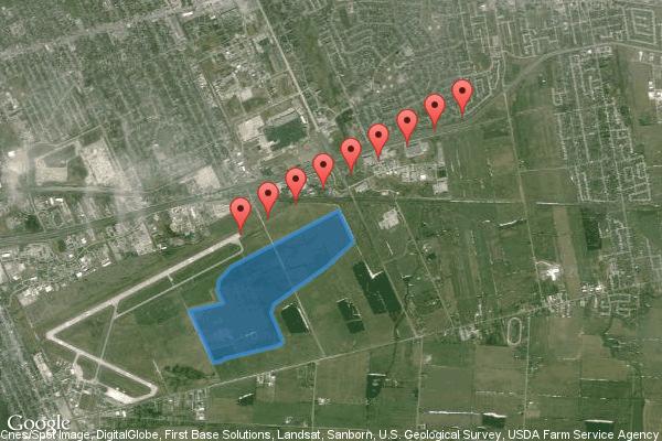
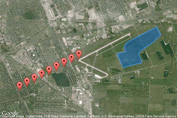
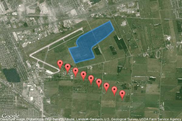
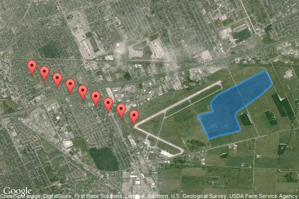
5 Windsor Solar Project Glare Analysis Report 2. DESCRIPTION OF THE PROJECT The Project will utilize approximately 197,000 to 208,000 solar panels of between watts (DC) each arranged with 18 modules in series and 11,111 strings in parallel. The solar modules will be ground mounted on 32 degree fixed tilt racks. All these strings are connected to kw (modified to 793 kw) inverters. The panel arrays consist of either 18 or 36 modules with each panel being approximately 2m wide and 1m high. The array spacing is 10m. The Project has been proposed to set the height of the low end of the array at about 0.6m above the finished grade. The basic configuration for this project is summarized in Table 1. Location YQG, Windsor International Airport, Ontario Table 1: General Configuration Windsor Solar Project Nameplate AC Capacity, MW AC; DC Capacity MW DC 50 MW AC; 60 MW DC Configuration Modules Inverter 32 fixed tilt racking 197,000 to 287,000 solar panels of between watts (DC) kw (modified to 793 kw) inverters Figure 1 illustrates the extent of the project location where the PV panels will be constructed and the relative locations to the YQG, Windsor International Airport runways and air traffic control tower. P a g e 2
 1/4-mile \") Threshold \") 1 ¼-mile \") 1-mile LAUZON PARKWAY LAUZON ROAD \") ¾-mile \") ½-mile \") 1/4-mile COUNTY Threshold \") \") 1/4-mile \") 1 ½-mile \") 1 ¾-mile \") 2-mile \") ½-mile \") ¾-mile")
 1 ½-mile \") 1 ¾-mile \") 2-mile CONCESSION ROAD 10 BASELINE ROAD CONCESSION ROAD 11 WINDSOR SAMSUNG SOLAR PROJECT DOUGALL PARKWAY \") &- Airport Receptors HIGHWAY 401 HIGHWAY 401 Imagery")

6 PLYMOUTH DRIVE PILLETTE ROAD JEFFERSON BOULEVARD ESSEX WAY LAUZON ROAD ") 2-mile ") 1 ¾-mile ") 1 ½-mile ") 1 ¼-mile ") 1-mile INTE ") 2-mile ") 1 ¾-mile ") 1 ½-mile E C ROW EXPRESSWAY ") ¾-mile ") ½-mile ") 1/4-mile ") Threshold ") 1 ¼-mile ") 1-mile LAUZON PARKWAY LAUZON ROAD ") ¾-mile ") ½-mile ") 1/4-mile COUNTY Threshold ") ") 1/4-mile ") 1 ½-mile ") 1 ¾-mile ") 2-mile ") ½-mile ") ¾-mile ") 1-mile ") 1 ¼-mile CABANA ROAD EAST WALKER ROAD PROVINCIAL ROAD 7TH CONCESSION ROAD &- DIVISION ROAD ") Threshold ") 1/4-mile ") ½-mile ") ¾-mile ") 1-mile CONCESSION ROAD 8 CONCESSION ROAD 9 ") 1 ¼-mile ") 1 ½-mile ") 1 ¾-mile ") 2-mile CONCESSION ROAD 10 BASELINE ROAD CONCESSION ROAD 11 WINDSOR SAMSUNG SOLAR PROJECT DOUGALL PARKWAY ") &- Airport Receptors HIGHWAY 401 HIGHWAY 401 Imagery 2014, Cnes/Spot Image, DigitalGlobe, First Base Solutions, Landsat, Sanborn, U.S. Geological Survey, USDA Farm Service Agency Traffic Control Tower Project Location Airport Runways WIndsor Solar Project and Receptors FIGURE #1 MAP DRAWING INFORMATION: DATA PROVIDED BY MNR GOOGLE EARTH PRO MAP CREATED BY: SFG MAP CHECKED BY: HL MAP PROJECTION: NAD 1983 UTM Zone 17N ² SCALE 1:35, km FILE LOCATION: I:\GIS\ Samsung Windsor\ mxd\glare Analysis.mxd PROJECT: STATUS: FINAL DATE: 09/05/14
7 Windsor Solar Project Glare Analysis Report 3. GLARE AND RECEPTORS At the time of conducting this analysis, there were no federally, provincially or municipally mandated requirements or guidelines regarding how to conduct the analysis of reflection/glare of sunlight from solar projects. In the absence of any Canadian guidelines for such analysis, the United States Federal Aviation Agency (FAA) interim policy 2 FAA Review of Solar Energy System Projects on Federally Obligated Airports was referenced. This analysis includes an evaluation of the potential glare on pilots and the air traffic control facility at the YQG, Windsor International Airport. Location 3.1 Potential Glare on Pilots and Control Facility at the YQG, Windsor International Airport YQG, Windsor International Airport operates on two runways, namely CL RNWY07 and CL RNWY12. Landing and take-off can occur on both sides of two runways. To conduct the analysis, the final approach path is defined as two miles from 50 ft. above the displaced landing threshold using a three degree glide path. Observation points (Receptors) are placed from the threshold crossing point to two miles with an interval of ¼ miles along the glide path. Table 2 lists the observation points. The air traffic control tower was also included for the analysis. The air traffic control tower is located at N, W, with an eye level height of 662 ft. ( m) above mean sea level. Latitude ( ) CL RNWY 07 East Approaching Longitude ( ) Table 2: List of Airport Receptors Height above Ground (ft.) Latitude ( ) CL RNWY 07 West Approaching Longitude ( ) Height above Ground (ft.) Threshold /4-mile ½-mile ¾-mile mile ¼-mile ½-mile ¾-mile mile P a g e 4
8 Windsor Solar Project Glare Analysis Report Location CL RNWY 12 East Approaching Latitude ( ) Longitude ( ) Height above Ground (ft.) Latitude ( ) CL RNWY 12 West Approaching Longitude ( ) Height above Ground (ft.) Threshold /4-mile ½-mile ¾-mile mile ¼-mile ½-mile ¾-mile mile P a g e 5
9 Windsor Solar Project Glare Analysis Report 4. GLARE PREDICTION METHOD The impact of glare from a solar project on receptors is dictated by a combination of factors including the position of the sun in the sky, tilt of solar panels, surface characteristics (reflectivity) of solar panel, spatial size of the solar project, as well as the relative location of the receptor to the solar panels. The position of sun in the sky is described by using solar elevation angle and solar azimuth. The solar elevation angle is the altitude of the sun, the angle between the horizon and the centre of the sun s disc, and expressed in degrees. A positive value of the solar elevation angle would indicate the sun s position after sunrise and before sun set while a negative value would indicate the sun s position before sunrise or after sun set. Solar azimuth defines in which direction the sun is. The most commonly accepted convention for solar energy applications, is to define the solar azimuth as the angle between a line due north and the shadow cast by a vertical rod on earth, so north is 0, east is 90, south is 180 and west is 270. Figure 2 graphically illustrates both the solar elevation angle and azimuth. The solar modules will be ground mounted on 32 degree fixed tilt racks, as shown in Figure 3. With solar panel orientation and position of sun, the direct solar reflection can be easily solved using geometry. The amount of sunlight being reflected by a surface is determined by the surface characteristics, typically termed as albedo which is the ratio of reflected solar radiation from the surface to incident solar radiation. Albedo is dimensionless and measured on a scale from zero for no reflection of a perfectly black surface to 1 for perfect reflection of a white surface. Solar panels with a single anti-reflective coating have an albedo of around which is similar to open water 3. The dominant land use at the project site is agricultural which has an albedo of around 0.14 to Therefore, the reflectivity of the solar panels for the project is similar or lower than that of the dominant land use in the project area. A glare analysis is to provide a quantified assessment of (1) when and where glare will occur throughout the year for a given solar project; and (2) potential effects on the human eye at locations (receptors) where glare occurs. In order to do this, the FAA has made available Solar Glare Hazard Analysis Tool (SGHAT) 4 to the public. The SGHAT was designed to determine whether a proposed solar energy project would result in glare at specified receptors and/or paths; and if glare is found, the tool calculates the retinal irradiance and subtended angle (size/distance) of the glare source to predict potential ocular hazards ranging from temporary after-image to retinal burn as defined in the FAA s Solar Glare Hazard Analysis Plot 2, as shown in Figure 4. FAA adopts the Solar Glare Hazard Analysis Plot as the standard for measuring the ocular impact of any proposed solar energy system on a federally-obligated airport. The SGHAT has been used in this analysis. 2 Lasnier and Ang, 1990, Photovoltaic Engineering Handbook. Taylor & Francis, New York. 3 United States Environmental Protection Agency, 2013, AERSURFACE User s Guide, EPA-454/B Sandia National Laboratories, 2014, Solar Glare Hazard Analysis Tool (SGHAT) User s Manual v. 2E (Accessed on June 12, 2014, P a g e 6
10 Solar Elevation Angle Windsor Solar Project Glare Analysis Report Figure 2: Sketch of Solar Position Sun North Azimuth West East South Figure 3: Sketch of Solar Panel Mounting Incident Sunlight Solar Reflection 1.3 m m P a g e 7
11 Windsor Solar Project Glare Analysis Report Figure 4: FAA s Glare Hazard Analysis Plot The SGHAT uses an interactive Google map where the user can define the outline of the proposed PV arrays, and specify receptors, and provides necessary information for sun position and vectorized geometry calculations. The inputs to the SGHAT are described in Tables 3-6. More details can be found in Appendix A. Table 3: Analysis Parameters Parameter Value Note Height unit ft. Subtended angle of the sun 0.5 Default Peak Direct Normal Irradiance 1000 W/m 2 Representative value DNI variability yes Scales by changing position of sun Ocular transmission coefficient 0.5 Default Pupil diameter m Daylight adjusted Eye focal length m Default Time interval 1 minute Yields excellent resolution P a g e 8
12 Windsor Solar Project Glare Analysis Report Table 4: PV Array Parameters Parameter Value Note Axis tracking Fixed tilt Panel tilt 32 Orientation of array 180 Facing south Rated power 50 MWac Reflectivity varies with incidence angle Yes Module surface material Light textured glass with anti-reflective coating Slope error 10 mrad Default Table 5: PV Array Vertex Parameters Latitude ( ) Longitude ( ) Ground Elevation Height above (ft.) Ground (ft.) Altitude (ft.) Table 6: Flight Path Parameters Parameter Value Note Flight path direction CL RNWY 07 approaching: 62 (west)/ 242 (east); CL RNWY 12 approaching: 116 (west)/ 296 (east); Glide slope 3 For all approaching paths Consider pilot visibility from cockpit Yes For all approaching paths Max downward viewing angle 30 Default Azimuthal viewing angle 180 Default Flight path observation point parameters are listed in Table 2. P a g e 9
13 Windsor Solar Project Glare Analysis Report 5. ANALYSIS RESULTS Detailed inputs and outputs of SGHAT are attached in Appendix A. The results of the analysis for flight paths are summarized in Table 7. Table 8 lists the assessment results for the air traffic control tower. In comparison to the FAA interim standard as shown in Figure 4, the analysis suggests: For aircraft approaching the two runways from the east, there is a low potential for glare, only between the threshold point and ¼-mile along the flight path, which can cause temporary afterimage (a lingering image of the glare in the field of view) during early morning around 7 am for less than 30 minutes from April to September. For aircraft approaching from the west, there is a potential for glare, along the flight paths, which can cause temporary after-image during early morning around 7 am for less than 30 minutes from March to September. At the air traffic control tower, there is a potential for glare which can cause temporary afterimage around 7 am for less than 30 minutes from late April to mid-september. Figure 5 shows a glare hazard analysis plot for an air traffic controller on June 21, 2014, which is the solstice for the site. This plot denotes the visual impact of glare predicted and indicates that the current panel configuration has the potential to cause the controller to have temporary after-image during the above-noted specific time period. Overall, based on SGHAT, the geometric configuration of the panels relative to the sunlight path and the inherently low reflectivity of the PV panels, the proposed Project will not result in hazardous glare conditions, in comparison to the FAA interim standard as shown in Figure 4. P a g e 10
14 Windsor Solar Project Glare Analysis Report Table 7: Summary of Potential Glare Impacts on the Fight Paths Location Potential Glare Impact CL RNWY 07 East Approaching Month of Occurrence Timing of Occurrence (around) Maximum Duration (min.) Potential Glare Impact CL RNWY 07 West Approaching Month of Occurrence Timing of Occurrence (around) Maximum Duration (min) Threshold LP4TA Apr-May, Aug-Sept 7 am < 30 P4TA Mar-Sep 7 am < 30 ¼ mile LP4TA Sep 7 am < 30 P4TA Mar-Sep 7 am < 30 ½ mile NG P4TA Mar-Sep 7 am < 30 ¾ mile NG P4TA Mar-Sep 7 am < 30 1 mile NG P4TA Mar-Sep 7 am < 30 1 ¼ mile NG P4TA Apr-Sep 7 am < 30 1 ½ mile NG P4TA Apr-Sep 7 am < 30 1 ¾ mile NG P4TA Apr-Aug 7 am < 30 2 mile NG P4TA Apr-Aug 7 am < 30 CL RNWY 12 East Approaching CL RNWY 12 West Approaching Location Potential Glare Impact Month of Occurrence Timing of Occurrence (around) Maximum Duration (min.) Potential Glare Impact Month of Occurrence Timing of Occurrence (around) Maximum Duration (min) Threshold LP4TA May-Aug 7 am < 30 P4TA Apr-Sep 7 am < 30 ¼ mile NG P4TA Mar-May, Jul-Sep 7 am < 30 ½ mile NG P4TA Mar-May, Aug-Sep 7 am < 30 ¾ mile NG P4TA Mar-May, Aug-Sep 7 am < 30 1 mile NG P4TA Mar-Apr, Aug-Sep 7 am < 30 1 ¼ mile NG P4TA Mar-Apr, Aug-Sep 7 am < 30 1 ½ mile NG P4TA Mar-Apr, Aug-Sep 7 am < 30 1 ¾ mile NG P4TA Mar-Apr, Sep 7 am < 30 2 mile NG P4TA Mar, Sep 7 am < 30 NG no glare LP4TA low potential for temporary after-image P4TA potential for temporary after-image P a g e 11
 Maximum Duration (min) P4TA Late-Apr to Mid-Sep 7 am < 30 Figure 5:")
15 Windsor Solar Project Glare Analysis Report Receptor Air Traffic Control Tower Table 8: Summary of Potential Glare Impacts on Air Traffic Control Tower Potential Glare Impact NG no glare LP4TA low potential for temporary after-image P4TA potential for temporary after-image Month of Occurrence Timing of Occurrence (around) Maximum Duration (min) P4TA Late-Apr to Mid-Sep 7 am < 30 Figure 5: Glare Hazard Analysis Plot for Traffic Controller on June 21, 2014 P a g e 12
16 Windsor Solar Project Glare Analysis Report APPENDIX A Glare Hazard Analysis Reports

17
18
19
20
21
22
23
24
25
26
27
28
29
30
31
32
33
34
35
36
37
38
39
40
41
42
43
44
45
46
47
48
49
50
51
52
53
54
55
56
57
58
59
60
61
62
63
64
65
66
67
68
69
70
71
72
73
74
75
76
^_ Key Observation Point Viewshed Model. Grazing Yak Solar Project. Key Observation Point Location Map KOP #6 KOP #3 KOP #1 KOP #2 KOP #4 KOP #5
 Liberty Rd Paint Mine Rd Mc Queen Rd Paint Mine Rd E q Funk Rd ^_ KOP #6 Currier Rd Washington Rd ^_ KOP #1 ^_ KOP #2 ^_ KOP #3 Hanisch Rd ^_ KOP #4 Judge Orr Rd ^_ KOP #5 0 1,000 2,000 Feet Solar Array
BEFORE THE PUBLIC SERVICE COMMISSION OF MARYLAND
 BEFORE THE PUBLIC SERVICE COMMISSION OF MARYLAND IN THE MATTER OF THE APPLICATION OF * MASON DIXON SOLAR CENTER, LLC FOR A CERTIFICATE OF PUBLIC * Case No.: 9426 CONVENIENCE AND NECESSITY TO CONSTRUCT
Centralized Forecasting Registration and Communication Requirements for Distribution Connected Variable Generators. IESO Training
 Centralized Forecasting Registration and Communication Requirements for Distribution Connected Variable Generators IESO Training May 2017 Centralized Forecasting - Registration and Communication Requirements
Glint and Glare Analysis
 Oasis C7 CPV Tracker Glint and Glare Analysis Abstract. Assessment of potential hazards from glint and glare from concentrated solar installations is an important requirement for public safety. This paper
Time Series Model of Photovoltaic Generation for Distribution Planning Analysis. Jorge Valenzuela
 Time Series Model of Photovoltaic Generation for Distribution Planning Analysis Jorge Valenzuela Overview Introduction: The solar problem and our limitations Modeling What information do we have? Solar
SHADOW STUDY REPORT REGARDING
 SHADOW STUDY REPORT REGARDING an APPLICATION TO REDEVELOP Three 6 Storey Condominiums Regional Road 25 (Ontario Street) and Britannia Road Milton, Ontario KNYMH FILE # 17030 Prepared by: Krista Lilley
Solar Time, Angles, and Irradiance Calculator: User Manual
 Solar Time, Angles, and Irradiance Calculator: User Manual Circular 674 Thomas Jenkins and Gabriel Bolivar-Mendoza 1 Cooperative Extension Service Engineering New Mexico Resource Network College of Agricultural,
Solar Glare Assessment for the Glass Façades of The SHARD
 Solar Glare Assessment for the Glass Façades of The SHARD Report ZE18035-TS July 2018 Zehndorfer Engineering Consulting e.u. Stift-Viktring-Str 21-6 9073 Klagenfurt Austria Jakob Zehndorfer, Dipl.-Ing.,
Exercise 6. Solar Panel Orientation EXERCISE OBJECTIVE DISCUSSION OUTLINE. Introduction to the importance of solar panel orientation DISCUSSION
 Exercise 6 Solar Panel Orientation EXERCISE OBJECTIVE When you have completed this exercise, you will understand how the solar illumination at any location on Earth varies over the course of a year. You
SOLAR PHOTOVOLTAIC ENERGY FACILITIES: ASSESSMENT OF POTENTIAL FOR IMPACT ON AVIATION. January Report No.10/344/RPS/1
 SOLAR PHOTOVOLTAIC ENERGY FACILITIES: ASSESSMENT OF POTENTIAL FOR IMPACT ON AVIATION January 2011 Report No.10/344/RPS/1 Spaven Consulting 2011 Reservoir House Gladhouse, Temple, Midlothian EH23 4TA, U.K.
Project No India Basin Shadow Study San Francisco, California, USA
 Project No. 432301 India Basin Shadow Study San Francisco, California, USA Numerical Modelling Studies 04 th June 2018 For Build Inc. Report Title: India Basin Shadow Study San Francisco, California, USA
Solar photovoltaic energy production comparison of east, west, south-facing and tracked arrays
 The Canadian Society for Bioengineering The Canadian society for engineering in agricultural, food, environmental, and biological systems. La Société Canadienne de Génie Agroalimentaire et de Bioingénierie
EE Properties of Sunlight. Y. Baghzouz Professor of Electrical Engineering
 EE 495-695 2.2 Properties of Sunlight Y. Baghzouz Professor of Electrical Engineering Azimuth angle The azimuth angle is the compass direction from which the sunlight is coming. At the equinoxes, the sun
Agricultural Science Climatology Semester 2, Anne Green / Richard Thompson
 Agricultural Science Climatology Semester 2, 2006 Anne Green / Richard Thompson http://www.physics.usyd.edu.au/ag/agschome.htm Course Coordinator: Mike Wheatland Course Goals Evaluate & interpret information,
Northern Alberta Institute of Technology
 Northern Alberta Institute of Technology Alternative Energy Program Solar Photovoltaic Reference Array Report March 31, 2016 Goals Provide solar energy system educators, installers and adopters with real
Motion of the Sun. View Comments
 Login 2017 Survey to Improve Photovoltaic Education Christiana Honsberg and Stuart Bowden View Comments Instructions 1. Introduction 2. Properties of Sunlight 2.1. Basics of Light Properties of Light Energy
Sunlight and its Properties II. EE 446/646 Y. Baghzouz
 Sunlight and its Properties II EE 446/646 Y. Baghzouz Solar Time (ST) and Civil (clock) Time (CT) There are two adjustments that need to be made in order to convert ST to CT: The first is the Longitude
Sunlight and its Properties Part I. EE 446/646 Y. Baghzouz
 Sunlight and its Properties Part I EE 446/646 Y. Baghzouz The Sun a Thermonuclear Furnace The sun is a hot sphere of gas whose internal temperatures reach over 20 million deg. K. Nuclear fusion reaction
Expedited Filing Draft August 22, 2017
 Applicability 1 Section 304.9 applies to: (a) (b) Requirements Expedited Filing Draft August 22, 2017 the legal owner of a wind or solar aggregated generating facility connected to the interconnected electric
ME 476 Solar Energy UNIT THREE SOLAR RADIATION
 ME 476 Solar Energy UNIT THREE SOLAR RADIATION Unit Outline 2 What is the sun? Radiation from the sun Factors affecting solar radiation Atmospheric effects Solar radiation intensity Air mass Seasonal variations
Solar reflected glare affecting visual performance
 Proceedings of 8 th Windsor Conference: Counting the Cost of Comfort in a changing world Cumberland Lodge, Windsor, UK, 10-13 April 2014. London: Network for Comfort and Energy Use in Buildings, http://nceub.org.uk
APPENDIX C GLARE REPORT
 APPENDIX C GLARE REPORT IMPERIAL VALLEY SOLAR COMPANY (IVSC) 2 SOLAR PHOTOVOLTAIC PROJECT Prepared by: Tetra Tech EC, Inc. 17885 Von Karman Avenue, Suite 500 Irvine, CA 92614-6213 Prepared for: Imperial
Short-term Solar Forecasting
 Short-term Solar Forecasting Presented by Jan Kleissl, Dept of Mechanical and Aerospace Engineering, University of California, San Diego 2 Agenda Value of Solar Forecasting Total Sky Imagery for Cloud
Chapter 1 Solar Radiation
 Chapter 1 Solar Radiation THE SUN The sun is a sphere of intensely hot gaseous matter with a diameter of 1.39 10 9 m It is, on the average, 1.5 10 11 m away from the earth. The sun rotates on its axis
Calculating equation coefficients
 Solar Energy 1 Calculating equation coefficients Construction Conservation Equation Surface Conservation Equation Fluid Conservation Equation needs flow estimation needs radiation and convection estimation
SHADOW STUDY REPORT REGARDING an APPLICATION TO REDEVELOP 6 Storey Condominium Louis Saint Laurent Ave & Leger Way Milton, Ontario
 SHADOW STUDY REPORT REGARDING an APPLICATION TO REDEVELOP 6 Storey Condominium Louis Saint Laurent Ave & Leger Way Milton, Ontario KNY FILE # 15145 Prepared by: Brad Ferguson & Wayne Harrison KNYMH INC.
Bi-annual Sun Tracking for Solar PV Module Support Structure: Study and Implementation
 16th NATIONAL POWER SYSTEMS CONFERENCE, 15th-17th DECEMBER, 2010 56 Bi-annual Sun Tracking for Solar PV Module Support Structure: Study and Implementation Prabodh Bajpai, Member IEEE, Vaishalee Dash, N.K.
Solar Photovoltaic Development Glint and Glare Guidance
 Solar Photovoltaic Development Glint and Glare Guidance October, 2018 Second edition ADMINISTRATION PAGE Reference: Author and Reviewers: Solar Photovoltaic Glint and Glare Guidance Danny Scrivener, Kai
Practice Questions: Seasons #1
 1. Seasonal changes on Earth are primarily caused by the A) parallelism of the Sun's axis as the Sun revolves around Earth B) changes in distance between Earth and the Sun C) elliptical shape of Earth's
Earth-Sun Relationships. The Reasons for the Seasons
 Earth-Sun Relationships The Reasons for the Seasons Solar Radiation The earth intercepts less than one two-billionth of the energy given off by the sun. However, the radiation is sufficient to provide
March 21. Observer located at 42 N. Horizon
 March 21 Sun Observer located at 42 N Horizon 48 June 21 March 21 A 48 90 S 23.5 S 0 23.5 N 42 N 90 N Equator (June 21) C (March 21) B A 71.5 48 Horizon 24.5 Observer Sun 40 Observer Sun 22 Observer Sun
Evaluating a Site s Solar Potential May, 2003
 Evaluating a Site s Solar Potential May, 2003 When evaluating a site s solar potential, there are several things to consider. Major points: 1. Area large enough to support in which to mount a solar system
COMPUTER PROGRAM FOR THE ANGLES DESCRIBING THE SUN S APPARENT MOVEMENT IN THE SKY
 COMPUTER PROGRAM FOR THE ANGLES DESCRIBING THE SUN S APPARENT MOVEMENT IN THE SKY B. BUTUC 1 Gh. MOLDOVEAN 1 Abstract: The paper presents software developed for the determination of the Sun-Earth geometry.
LESSON PLAN - Optimum Orientation of Solar Panels Using Soltrex Data
 LESSON PLAN - Optimum Orientation of Solar Panels Using Soltrex Data Title of Lesson: Optimum Orientation of Solar Panels Using Soltrex Data Description of class: High School physics, astronomy, or environmental
Purdue University Bifacial Module Calculator (PUB)
") Purdue University Bifacial Module Calculator (PUB) Date: 02/18/2018 Purdue University Bifacial Module Calculator (PUB) is a module-level simulator that can accurately model and optimize the performance
Purdue University Bifacial Module Calculator (PUB) Date: 02/18/2018 Purdue University Bifacial Module Calculator (PUB) is a module-level simulator that can accurately model and optimize the performance
Observer-Sun Angles. ), Solar altitude angle (α s. ) and solar azimuth angle (γ s )). θ z. = 90 o α s
, Solar altitude angle (α s. ) and solar azimuth angle (γ s )). θ z. = 90 o α s") Observer-Sun Angles Direction of Beam Radiation: The geometric relationships between a plane of any particular orientation relative to the earth at any time and the incoming beam solar radiation can be
Observer-Sun Angles Direction of Beam Radiation: The geometric relationships between a plane of any particular orientation relative to the earth at any time and the incoming beam solar radiation can be
LAB 3: THE SUN AND CLIMATE NAME: LAB PARTNER(S):
:") GEOG 101L PHYSICAL GEOGRAPHY LAB SAN DIEGO CITY COLLEGE SELKIN 1 LAB 3: THE SUN AND CLIMATE NAME: LAB PARTNER(S): The main objective of today s lab is for you to be able to visualize the sun s position
GEOG 101L PHYSICAL GEOGRAPHY LAB SAN DIEGO CITY COLLEGE SELKIN 1 LAB 3: THE SUN AND CLIMATE NAME: LAB PARTNER(S): The main objective of today s lab is for you to be able to visualize the sun s position
13 SHADOW FLICKER Introduction Methodology
 Table of contents 13 SHADOW FLICKER... 13-1 13.1 Introduction... 13-1 13.2 Methodology... 13-1 13.2.1 Factors Influencing Shadow Flicker Occurrence... 13-2 13.2.2 Shadow Flicker Analysis Methodology...
Earth Science Seasons Test Name Per Date
 Name Per Date Page 1 1. The diagram below represents four positions of the Earth as it revolves around the Sun. 5. Base your answer to the following question on the diagram below, which shows the apparent
Which Earth latitude receives the greatest intensity of insolation when Earth is at the position shown in the diagram? A) 0 B) 23 N C) 55 N D) 90 N
 0 B) 23 N C) 55 N D) 90 N") 1. In which list are the forms of electromagnetic energy arranged in order from longest to shortest wavelengths? A) gamma rays, x-rays, ultraviolet rays, visible light B) radio waves, infrared rays, visible
1. In which list are the forms of electromagnetic energy arranged in order from longest to shortest wavelengths? A) gamma rays, x-rays, ultraviolet rays, visible light B) radio waves, infrared rays, visible
For most observers on Earth, the sun rises in the eastern
 632 CHAPTER 25: EARTH, SUN, AND SEASONS WHAT IS THE SUN S APPARENT PATH ACROSS THE SKY? For most observers on Earth, the sun rises in the eastern part of the sky. The sun reaches its greatest angular altitude
PHOTOVOLTAIC SOLAR ENERGY TRAINER DL SOLAR-D1 Manual
 PHOTOVOLTAIC SOLAR ENERGY TRAINER DL SOLAR-D1 Manual DL SOLAR-D1 Contents 1. Solar energy: our commitment 5 to the environment 1.1. Basic principles and concepts 6 Mechanical work, energy and power: 6
WYANDOTTE MUNICIPAL SERVICES COMMUNITY WIND ENERGY PROJECT WIND RESOUCE SUMMARY
 WYANDOTTE MUNICIPAL SERVICES COMMUNITY WIND ENERGY PROJECT WIND RESOUCE SUMMARY MONTHLY REPORT October 15, 2007 Black & Veatch Project: 144374 Prepared by: Black & Veatch Corporation 6300 S. Syracuse Way
INVESTIGATIONS ON SOLAR THERMAL PROCESS HEAT INTEGRATION WITH PARABOLIC TROUGH COLLECTORS
 INVESTIGATIO ON SOLAR THERMAL PROCESS HEAT INTEGRATION WITH PARABOLIC TROUGH COLLECTORS Heinz Marty and Elimar Frank HSR University of Applied Science of Rapperswil, Institut fuer Solartechnik SPF, 8640
FAA AIRFIELD LIGHTING STANDARDS UPDATE
 FAA AIRFIELD LIGHTING STANDARDS UPDATE Present to: IES ALC GOVERNMENT LIGHTING COMMITTEE WASHINGTON, DC May 7, 2015 Tom Mai FAA Airport Engineering Division (AAS-100) Agenda FAA Airfield Lighting Equipment
5. In which diagram is the observer experiencing the greatest intensity of insolation? A) B)
 B)") 1. Which factor has the greatest influence on the number of daylight hours that a particular Earth surface location receives? A) longitude B) latitude C) diameter of Earth D) distance from the Sun 2. In
1. Which factor has the greatest influence on the number of daylight hours that a particular Earth surface location receives? A) longitude B) latitude C) diameter of Earth D) distance from the Sun 2. In
CUTTING Shadows SOME CUTOUT DIALS FOR YOUR AMUSEMENT. ALL YOU NEED ARE SOME SCISSORS, AND YOUR LATITUDE, AND LONGITUDE.
 CUTTING Shadows SOME CUTOUT DIALS FOR YOUR AMUSEMENT. ALL YOU NEED ARE SOME SCISSORS, AND YOUR LATITUDE, AND LONGITUDE. Simon Wheaton-Smith December 2009 CUTOUTS FOR PAPER SUN DIALS armillary (also equatorial
OF THE IMPACT OF PARTIAL SHADING ON THE PERFORMANCE OF A GRID-TIED PHOTOVOLTAIC SYSTEM
 OF THE IMPACT OF PARTIAL SHADING ON THE PERFORMANCE OF A GRID-TIED PHOTOVOLTAIC SYSTEM K. Hurayb, Y. Moumouni, F. A. da Silva,Y. Baghzouz Electrical & Computer Engineering Department University of Nevada,
SIMPLE LOW CONCENTRATING MODULE DESIGN INCRESES SOLAR CELL OUTPUT 25%
 SIMPLE LOW CONCENTRATING MODULE DESIGN INCRESES SOLAR CELL OUTPUT 25% Daniel Simon 3D Solar, Inc. 5555 N. Sheridan Rd. #1003 Chicago, IL 60640 e-mail: daniel@3dsolar.com ABSTRACT We present a simple low
SHADOW - Main Result. windpro CUMULTATIEVE EFFECTEN SLAGSCHADUW HERENTALS. EDF Luminus Markiesstraat Brussel
 SHADOW - Main Result Assumptions for shadow calculations Maximum distance for influence Calculate only when more than 20 % of sun is covered by the blade Please look in WTG table Minimum sun height over
OPTIMIZATION OF GLOBAL SOLAR RADIATION OF TILT ANGLE FOR SOLAR PANELS, LOCATION: OUARGLA, ALGERIA
 OPTIMIZATION OF GLOBAL SOLAR RADIATION OF TILT ANGLE FOR SOLAR PANELS, LOCATION: OUARGLA, ALGERIA Mohamed Lakhdar LOUAZENE Dris KORICHI Department of Electrical Engineering, University of Ouargla, Algeria.
TILT, DAYLIGHT AND SEASONS WORKSHEET
 TILT, DAYLIGHT AND SEASONS WORKSHEET Activity Description: Students will use a data table to make a graph for the length of day and average high temperature in Utah. They will then answer questions based
Analysis of the Performance a PV System Based on Empirical Data in a Real World Context
 Analysis of the Performance a PV System Based on Empirical Data in a Real World Context Seyed Amin Tabatabaei and Jan Treur Abstract The performance of solar energy production systems consisting of photovoltaic
Which graph best shows the relationship between intensity of insolation and position on the Earth's surface? A) B) C) D)
 B) C) D)") 1. The hottest climates on Earth are located near the Equator because this region A) is usually closest to the Sun B) reflects the greatest amount of insolation C) receives the most hours of daylight D)
1. The hottest climates on Earth are located near the Equator because this region A) is usually closest to the Sun B) reflects the greatest amount of insolation C) receives the most hours of daylight D)
IV. ENVIRONMENTAL IMPACT ANALYSIS B. AESTHETICS SHADE/SHADOW
 IV. ENVIRONMENTAL IMPACT ANALYSIS B. AESTHETICS SHADE/SHADOW 1. INTRODUCTION Potential effects of the Proposed Project related to visual character, views and light/glare are addressed in Section IV.A,
Solar Radiation and Solar Programs. Training Consulting Engineering Publications GSES P/L
 Solar Radiation and Solar Programs Training Consulting Engineering Publications SOLAR RADIATION Purposes of Solar Radiation Software Successful project planning and solar plant implementation starts by
SHADOW FLICKER TURBINE LAYOUT 6A GULLEN RANGE WIND FARM GOLDWIND AUSTRALIA
 SHADOW FLICKER TURBINE LAYOUT 6A GULLEN RANGE WIND FARM GOLDWIND AUSTRALIA Document Control Status Written by Approved by Date Comment Revision A T.Lam D.Bolton 14/03/14 Initial Revision B T.Lam D.Bolton
AWOS Level Descriptions
 AWOS Level Descriptions AWOS System Configurations. The AWOS is a modular system utilizing a central processor which may receive input from several sensors. Eight standard groups of sensors are defined
Model 3024 Albedometer. User s Manual 1165 NATIONAL DRIVE SACRAMENTO, CALIFORNIA WWW. ALLWEATHERINC. COM
 Model 3024 Albedometer User s Manual 1165 NATIONAL DRIVE SACRAMENTO, CALIFORNIA 95834 WWW. ALLWEATHERINC. COM TABLE OF CONTENTS INTRODUCTION... 1 THEORY OF OPERATION... 2 General Description... 2 Accuracy...
Appendix A Zoning Ordinance
 Appendix A Zoning Ordinance Appendix A Zoning Ordinance Sec. 94-164. Brookings Airport Zoning Ordinance. (a) Purpose and authority. (1) It is hereby found that an airport obstruction has the potential
Basic human requirements
 Basic human requirements Core Temperature 37 0 C 36 0 C 34 0 C 32 0 C 31 0 C 28 0 C Room Temperature 0 o C 20 o C 35 o C Energy [kw/(m² μm)] 2.0-1.5 - Black body at 800 K Solar radiation at atmosphere
Algonquin Power Co. Shadow Flicker Impact Assessment. Amherst Island Wind Project. For. H Rev. 2 February 26, 2013
 Algonquin Power Co. Shadow Flicker Impact Assessment For Amherst Island Wind Project H340642-0000-50-124-0001 Rev. 2 February 26, 2013 Algonquin Power Co. (on behalf of Windlectric Inc.) voluntarily authorized
Latitude and Longitude. North. Latitude. South
 Latitude and Longitude North Latitude Longitude South 54 North America 55 Longitude Latitude United States 56 Latitude New York 72w 44n 42n 57 Site Location The site location is specified by a latitude
SHADOW IMPACT STUDY REPORT
 SHADOW IMPACT STUDY REPORT 175 Zoo Park Road Town of Wasaga Beach Date: September 2017 Prepared for: Simcoe County Housing Corporation Prepared by: MacNaughton Hermsen Britton Clarkson Planning Limited
Analyzing Solar Energy Graphs: MY NASA DATA
 LIVE INTERACTIVE LEARNING @ YOUR DESKTOP Analyzing Solar Energy Graphs: MY NASA DATA Presented by: Alissa Keil September 12, 2011 MY NASA DATA Know your Earth video http://www.youtube.com/watch? v=d2kh_z720ia
5.6.2 SHADOW / DAYLIGHT ASSESSMENT
 ENVIRONMENTAL IMPACT STATEMENT 5.6.2 SHADOW / DAYLIGHT ASSESSMENT 5.6.2.1 Introduction As part of the Environmental Impact Study (EIS) required for the planning submission for the proposed 120 bed wing
2018 Annual Review of Availability Assessment Hours
 2018 Annual Review of Availability Assessment Hours Amber Motley Manager, Short Term Forecasting Clyde Loutan Principal, Renewable Energy Integration Karl Meeusen Senior Advisor, Infrastructure & Regulatory
Computer Activity #3 SUNRISE AND SUNSET: THE SEASONS
 NAME(S)!!!!!!!!!!!!!!!!!!!!!!!!!!!!!!!!!! ASTRONOMY 25 Computer Activity #3 SUNRISE AND SUNSET: THE SEASONS SECTION DAY/TIME S. V. LLOYD Overview The seasonal variation in temperature is due to two changes
SHADOW FLICKER MODELING ANALYSIS
 KENT HILLS 3: KENT HILLS WIND FARM EXPANSION PHASE 3 Appendix K Shadow Flicker Modeling Analysis SHADOW FLICKER MODELING ANALYSIS KENT HILLS 3: KENT HILLS WIND FARM EXPANSION PHASE 3 Appendix K Shadow
Paine Field Airport Existing and Future Environmental Assessment, Initiation of Commercial Service Noise Analysis
 Paine Field Airport Existing and Future Environmental Assessment, Initiation of Commercial Service Noise Analysis July 2012 Prepared by: BridgeNet International 3151 Airway Avenue Building I-2 Costa Mesa,
MiSP Astronomy - Seasons Worksheet #1 L2
 MiSP Astronomy - Seasons Worksheet #1 L2 Name Date Changing Hours of Daylight on Long Island (L 1, 2, 3) Introduction You sometimes hear people say, Days are longer in the summer and shorter in the winter.
Towards a Bankable Solar Resource
 Towards a Bankable Solar Resource Adam Kankiewicz WindLogics Inc. SOLAR 2010 Phoenix, Arizona May 20, 2010 Outline NextEra/WindLogics Solar Development Lessons learned TMY - Caveat Emptor Discussion 2
CHAPTER 3 PROBLEM DEFINITION AND OBJECTIVE
 49 CHAPTER 3 PROBLEM DEFINITION AND OBJECTIVE 3.1 MOTIVATION Concentrating solar power is a principle of increasing solar power density. It can be demonstrated to set a piece of paper on fire by using
Tennessee Valley Authority. Thermal Assessment of Existing 161kv & 500kv Transmission Lines
 Tennessee Valley Authority Thermal Assessment of Existing 161kv & 500kv Transmission Lines TVA Power Service Area Why are we gathering aerial laser survey & doing thermal assessments? Before 1977; NESC
Photovoltaic Systems Engineering
 Photovoltaic Systems Engineering Ali Karimpour Associate Professor Ferdowsi University of Mashhad Reference for this lecture: Photovoltaic Systems Engineering Third Edition CRC Roger Messenger, Jerry Ventre
THE SOLAR RESOURCE: PART I MINES ParisTech Center Observation, Impacts, Energy (Tel.: +33 (0) )
 )") MASTER REST Solar Resource Part I THE SOLAR RESOURCE: PART I MINES ParisTech Center Observation, Impacts, Energy philippe.blanc@mines-paristech.fr (Tel.: +33 (0)4 93 95 74 04) MASTER REST Solar Resource
MASTER REST Solar Resource Part I THE SOLAR RESOURCE: PART I MINES ParisTech Center Observation, Impacts, Energy philippe.blanc@mines-paristech.fr (Tel.: +33 (0)4 93 95 74 04) MASTER REST Solar Resource
APPENDIX N View Impact & Shadow Analysis
 Permit Application Document TABLE OF CONTENTS 1.0 VIEW IMPACT ANALYSIS... 2 1.1 Overview... 2 1.2 View Impact Assessment Methodology... 2 1.3 Site Description... 3 1.4 Comparative Structure Heights...
WIND DATA REPORT FOR THE YAKUTAT JULY 2004 APRIL 2005
 WIND DATA REPORT FOR THE YAKUTAT JULY 2004 APRIL 2005 Prepared on July 12, 2005 For Bob Lynette 212 Jamestown Beach Lane Sequim WA 98382 By John Wade Wind Consultant LLC 2575 NE 32 nd Ave Portland OR 97212
R.L. Kellogg, Ph.D. North American Sundial Society June 2013
 R.L. Kellogg, Ph.D. North American Sundial Society June 2013 1 Analemmatic Sundials The Human Sundial The Analemmatic Sundial or Human Sundial was first described by M. de Vaulezard in 1640 in a Treatise
Purdue University Meteorological Tool (PUMET)
") Purdue University Meteorological Tool (PUMET) Date: 10/25/2017 Purdue University Meteorological Tool (PUMET) allows users to download and visualize a variety of global meteorological databases, such as
Purdue University Meteorological Tool (PUMET) Date: 10/25/2017 Purdue University Meteorological Tool (PUMET) allows users to download and visualize a variety of global meteorological databases, such as
FLATE Hillsborough Community College - Brandon (813)
") The Florida Advanced Technological Education (FLATE) Center wishes to make available, for educational and noncommercial purposes only, materials relevant to the EST1830 Introduction to Alternative/Renewable
The Florida Advanced Technological Education (FLATE) Center wishes to make available, for educational and noncommercial purposes only, materials relevant to the EST1830 Introduction to Alternative/Renewable
Literature Review: 1.
 Literature Review: 1. The Solar Tracker, a device that keeps photovoltaic or photo-thermal panels in an optimum position perpendicularly to the solar radiation during daylight hours, can increase the collected
Student Exploration: Seasons: Earth, Moon, and Sun
 Name: Date: Student Exploration: Seasons: Earth, Moon, and Sun Vocabulary: altitude, axis, azimuth, equinox, horizon, latitude, revolution, rotation, solstice Prior Knowledge Questions (Do these BEFORE
AC : UTPA SOLAR SYSTEM EFFICIENCY
 AC 2012-3376: UTPA SOLAR SYSTEM EFFICIENCY Mr. Leonel Aguilera, University of Texas, Pan American Leonel Aguilera earned his his B.S degree in electrical engineering from the Technology Institute of Saltillo,
The celestial sphere, the coordinates system, seasons, phases of the moon and eclipses. Chapters 2 and S1
 The celestial sphere, the coordinates system, seasons, phases of the moon and eclipses Chapters 2 and S1 The celestial sphere and the coordinates system Chapter S1 How to find our way in the sky? Let s
Chapter Seven. Solar Energy
 Chapter Seven Solar Energy Why Studying Solar energy To know the heat gain or heat loss in a building In making energy studies In the design of solar passive homes. Thermal Radiation Solar spectrum is
Appendix I Shadow Flicker Report
 Appendix I Shadow Flicker Report Report Wind Turbine Shadow Flicker Analysis Update For McLean s Mountain Wind Farm Prepared for: Attention: Dillon Consulting Ltd. 235 Yorkland Blvd., Suite 800 Toronto,
Lecture 9: Reference Maps & Aerial Photography
 Lecture 9: Reference Maps & Aerial Photography I. Overview of Reference and Topographic Maps There are two basic types of maps? Reference Maps - General purpose maps & Thematic Maps - maps made for a specific
Creating PET Adjustment Coefficients
 Creating PET Adjustment Coefficients James Dyer Department of Geography Ohio University I. Computing Daily Solar Radiation In ArcToolbox: Spatial Analyst Tools Solar Radiation Area Solar Radiation. Use
HORIZONTAL PROJECTION PARAMETERS: DANE COUNTY COORDINATES
 Recommended RTK GPS Configuration Parameters for the City of Madison, WI Base Station Compiled by: Dan Rodman RLS, City of Madison (608)266-6674 drodman@cityofmadison.com For base station information see
ELECTRONICS DIVISION INTERNAL REPORT NO. 324
 NATIONAL RADIO ASTRONOMY OBSERVATORY Green Bank, West Virginia ELECTRONICS DIVISION INTERNAL REPORT NO. 324 NRAO 43m Antenna Coordinates and Angular Limits (Version 4) Glen Langston September 14, 2012
UNITED KINGDOM FOREIGN AND COMMONWEALTH OFFICE, DRAGON CAPITAL GROUP
 UNITED KINGDOM FOREIGN AND COMMONWEALTH OFFICE, DRAGON CAPITAL GROUP SOLAR OUTPUT AT PEAK TARIFF FOR DIFFERENT SLOPE AND ORIENTATION IN HOCHIMINH CITY ARTELIA Vietnam Ho Chi Minh City Office 6 Phung Khac
Solar Analysis. ST =CT + 4min 1 o (LTM LL)+E+1 (1) E=9.87 sin 2 B 7.53 cosb 1.5 sinb (2)
+E+1 (1) E=9.87 sin 2 B 7.53 cosb 1.5 sinb (2)") Solar Analysis The first step in the calculations is determining the solar insolation in the region that SPAAV will be located, which is Lake Ontario. The data for average daily insolation can be found
Solar Analysis The first step in the calculations is determining the solar insolation in the region that SPAAV will be located, which is Lake Ontario. The data for average daily insolation can be found
ILLUSTRATING SHADOWS TABLE OF CONTENTS
 ILLUSTRATING SHADOWS TABLE OF CONTENTS 316 pages Introduction Chapter Page Introduction and "A Quick Hands On Project" Part One 1 10 The approximate evolution of the dial 2 13 How the earth does its thing
NABCEP Entry Level Exam Review Solfest practice test by Sean White
 1. A fall protection system must be in place for all work done at heights in excess of a. 4 feet b. 6 feet c. 8 feet d. 10 feet 2. A circuit breaker performs the same function a. as a fuse b. as a switch
CLIMATE OVERVIEW. Thunder Bay Climate Overview Page 1 of 5
 CLIMATE OVERVIEW The climate in the Thunder Bay area is typical of a mid-latitude inland location with a Great Lake Moderating influence. The moderating effect of Lake Superior results in cooler summer
Attachment E: CADP Design Shadow Analysis
 Attachment E: CADP Design Shadow Analysis June 6, 2016 TO: Don Lewis San Francisco Planning Department 1650 Mission Street, Suite 400 San Francisco, CA 94103 SUBJECT: 2060 Folsom Street 17 th & Folsom
Outline. The Path of the Sun. Emissivity and Absorptivity. Average Radiation Properties II. Average Radiation Properties
 The Path of the Sun Larry Caretto Mechanical Engineering 83 Alternative Energy Engineering II March, 2 Outline Review radiation properties for solar collectors Orientation of earth and sun Earth-based
Prediction of Capacity Factor for Near-Optimised Solar PV Systems in Sheffield, UK
 Sheffield Solar Prediction of Capacity Factor for Near-Optimised Solar PV Systems in Sheffield, UK A case study using third order response surface profiling of realworld PV generation data to predict potential
Terms of Reference for the Comparative Environmental Review (CER) of. Options for the Mactaquac Project, Mactaquac, New Brunswick
 of. Options for the Mactaquac Project, Mactaquac, New Brunswick") Terms of Reference for the Comparative Environmental Review (CER) of Options for the Mactaquac Project, Mactaquac, New Brunswick Preamble The New Brunswick Power Corporation ( NB Power ) operates the Mactaquac
Terms of Reference for the Comparative Environmental Review (CER) of Options for the Mactaquac Project, Mactaquac, New Brunswick Preamble The New Brunswick Power Corporation ( NB Power ) operates the Mactaquac