Pb1 y13 =-j10 Pb5. Pb4. y34 =-j10
|
|
|
- Stanley Park
- 5 years ago
- Views:
Transcription
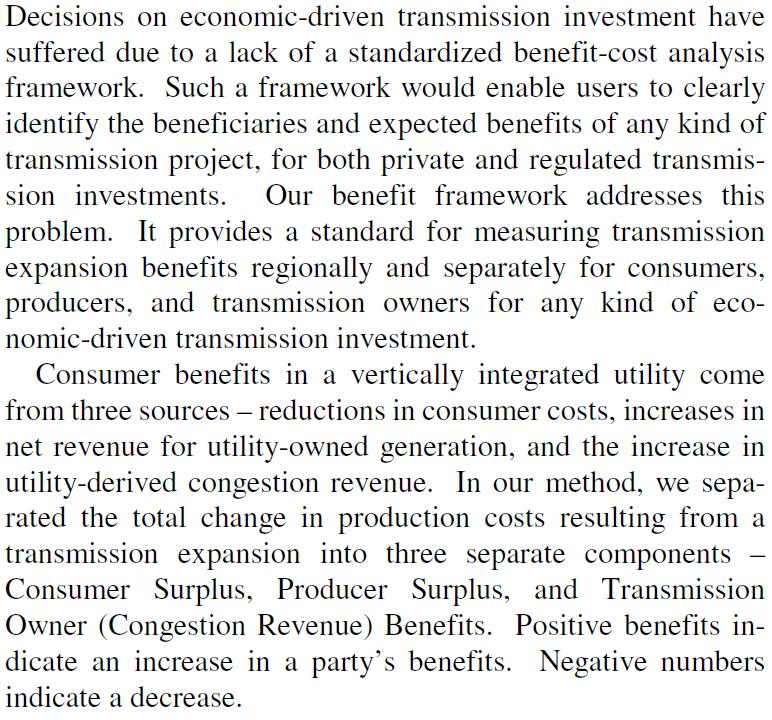
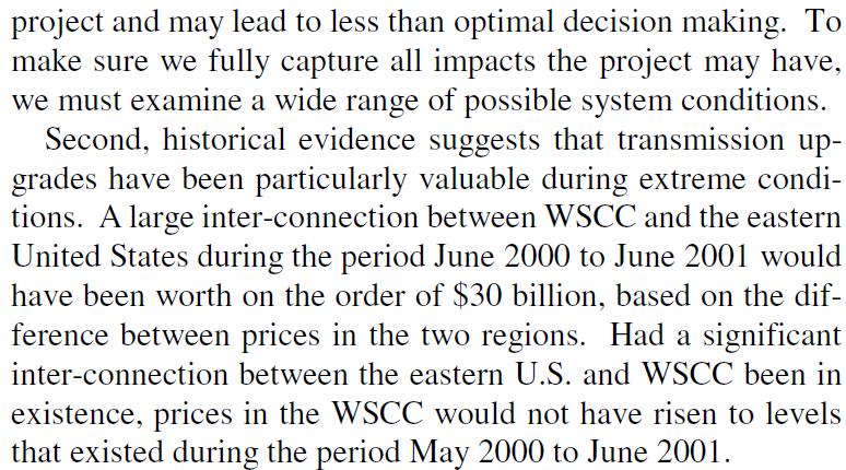
1 EE 55, Exam, ake-home. Due Monday, April, 06, 5:00pm. You may use class notes or any reference materials (e.g., books, etc.) that you like; however, you must work alone, i.e., you should not be communicating with anyone else about how to work the problems on this exam.. Generation planning (5 pts): Develop the complete set of equations for generation expansion plan formulation -b (GEP-b), based on the following data and assumptions. a. Plan for 30 years, at 5 year intervals (thus you should have 6 investment periods (at years 5, 0, 5, 0, 5, and 30). b. Use annual discount rate of 9%. c. Maintain a reserve of 5% above peak load. d. Assume a CO cost of $5/M (you will need to add a term to the objective function to account for this). e. ransmission topology and data: wo comments follow Note the definitions of positive branch flow for each P bk, k=,,5. he admittances y ij are given on a 00 MVA power base. Pg Pg Pb3 y =-j0 Pb3 y4 =-j0 Pb y3 =-j0 Pb5 Pd y3 =-j0 4 Pb4 y34 =-j0 3 Pg4 Pd3 f. Line flow constraints: -500MW P bk 5000MW, k=,5. he per-unit expressions of these constraints, on a 00 MVA power base, are -500 P bk 500. Given the level of loads (see item (j) below), this implies the transmission has infinite capacity. g. Existing generation data: Bus Bus Bus 4 echnology PC (j=) NGCC (j=3) C (j=4) Capacity (MW) h. echnology characteristics PC (j=) PC (j=) NGCC(j=3) C (j=4) Wind (j=5) Capacity credit Investment cost (000$/MW) Fixed O&M costs (000$/MW/yr) Var O&M ($/MWhr) Full-load heat rate (MBU/MWhr) Fuel cost ($/MBU) CO emissions (lbs/mwhr) Capacity factor 0.35 Salvage value (000$/MW)
2 i. Load duration curve and corresponding blocks. Assume a load growth rate of %/year, applied to each value d, d, d 3, for each of the two loads in the system, with the durations h, h, and h 3 remaining the same. herefore, for example, for the load at bus, d would be.0,.084,.95,.395,.4568,.6084,.7758 pu for years, 5, 0, 5, 0, 5, and 30, respectively. You will need to compute the values of d and d 3 for these years as well. hen you will need to do the same for the load at bus 3. d d L (MW) d3 h h+h h+h+h3 Number of hours that Load > L Initial load at bus (Pg) Block Block Block 3 Load (pu) d = d = d 3 =0.6 Duration (hrs) h =000 h =5000 h 3 =760 Initial load at bus 3 (Pg3) Block Block Block 3 Load (pu) d =. d =0.9 d 3 =0.7 Duration (hrs) h =900 h =500 h 3 =660. Production costing ( pts): a. (4 pts) A load duration curve characteries the next year for a power system is given below. he power system is supplied by one 3 MW unit. Identify the minimum load, the loss of load probability, the loss of load expectation, and the expected unserved energy, assuming the 3 MW unit is perfectly reliable. 0.6 F Dr ( d e ) 0. d e (MW) Solution: Minimum Load= MW, LOLP=P(d>3)=0.333, LOLE=0.333*8760=97 hrs EUE=Area*=0.5()(.333)(8760)=0.666(8760)=460MWhrs
3 Solution: b. (5 pts) Now consider that the power system is supplied with one 4 MW unit having a forced outage rate of 0.5. he load is still characteried by the load duration curve above. Compute loss of load probability, loss of load expectation, and expected unserved energy. f Dj (d j ) 0.6 F Dr ( d e ) * 0. d e (MW) 0, (b) C = (c) (d) d e d e = F r ( () d D e ) (e) d e So LOLP=P(d>4)=0.5, LOLE=0.5*8760=90hrs EUE=8760{()(0.5)+0.5(3)(0.5)}=8760{ }=5475MWhrs c. (3 pts) Consider the two situations you have assessed in parts (a) and (b) of this problem. Complete the following sentence: Although situation has the larger LOLP; situation has the larger EUE because. Solution: Although situation (a) has a larger LOLP, situation (b) has a larger EUE because when load is interrupted in situation (a), it will only be for 0 to MW, whereas when load is interrupted in situation (b), it will be for 0 to 4 MW.
4 d. (4 pts) Compute the energy expected to be produced by the 4 MW unit of the year. Solution: E=A**Area where Area is computed from the previous load duration curve, i.e., the one before the unit was convolved in, according to Area x x j j F ( j) D e ( ) d his is the load duration curve given in the problem statement. In this case, x j- =0 and x j =4, and so the area is A=()()+0.5(3)()=.5. he availability is 0.75 so that E=0.75*8760*.5=645 MWhrs. e. (3 pts) Assume the 4 MW unit is a thermal unit. What is the minimum additional information you need to know to compute the cost incurred by unit 4 in producing the amount of energy developed in part (d)? Solution: We need the heat rate and the fuel price. f. (3 pts) After reviewing a production cost program which computes annual production costs in a way that is similar to the procedure suggested in parts (a)-(c) of this problem, an engineer decides to write a production cost simulation program that will allow representation of the power system with much greater operational fidelity. What is the single most important change that the engineer needs to make, relative to that suggested in parts (a)-(e)? Solution: he engineer needs to represent the power system chronologically, hour by hour. 3. Benders (7 pts): he relation between primal and dual optimiations can be stated as: Primal max s. t. x 0 c A x b subproblem A w * Consider the following problem: max subject to : x 4x 5w w 0, : x w 0 x 3w 8 w, x 0, w Dual subproblem : min s. t. A integer 0 c b A w* a. (4 pts) Express this problem in the form of Benders, i.e., express an appropriate master problem and an appropriate (primal) subproblem.
5 Solution: Master problem: max s.t 5w Q : w 0, Subproblem: x 0 * * max 4x subject to x 0 w x 8 3w M, b. (3 pts) Identify an initial solution to the master. Solution: * M, w 0 w 0, w integer c. (4 pts) Formulate the subproblem dual in terms of w*, and based on the dual formulation, and the solution to the master problem found in part (b), explain why you know that the primal subproblem is infeasible. Solution: We first express the subproblem dual. c 4, c 5, A, A, 3 b min s. t. 0 A c ( b A w*), 0 Substituting w*=0, the subproblem dual becomes: min s. t. 4, min s. t * 8 3 w
6 Because the all coefficients in the objective are negative, and the variables are constrained to be non-negative, the subproblem dual is unbounded; an unbounded dual necessarily implies that the corresponding subproblem primal must be infeasible. d. (3 pts) Given the sub-problem primal is infeasible, explain why it is possible that we may still find a solution to this problem (and thus, that this solution will be feasible in the subproblem primal). Solution: he reason that we may still find a solution to this problem, in spite of the fact that the subproblem primal is infeasible in this step, is that the subproblem primal is expressed in terms of w*. If we further constrain w*, it will affect the subproblem primal s feasibility region. e. (3 pts) Find a constraint on w which will make the subproblem primal feasible. Solution: he feasibility constraint can be found by expressing (b-a w) λ 0, or 0 w 8 3 which results in from which we observe that 0 (0 w) (8 3 w) 0 0 w 0 83w 0 or 8 0 w w 3 And we conclude that w 8/3. 4. Planning principles (0 pts): A good paper on planning (you should read in its entirety - it can be found in IEEE XPlore) is: M. Awad, S. Broad, K. Casey, J. Chen, A. Geevarghese, J. Miller, A. Pere, A. Sheffrin, M. Zhang, E. oolson, G. Drayton, A. Rahimi, and B. Hobbs, he California ISO transmission economic assessment methodology (EAM): principles and application to Path 6, Power Engineering Society General Meeting, 006. his paper lists five principles to economic evaluation of proposed transmission upgrades. I have chosen from the paper an excerpt for each principle. For each one, identify how you would implement this principle. Where appropriate, base your answer on information, concepts, and/or methods we have covered in EE 55. I am expecting from you at minimum a -3 sentence paragraph for each principle. First key principle: Benefit Framework: Second key principle: Network Representation:
7 hird key principle: Market Prices: Fourth key principle: Uncertainty:

8 Fifth key principle: Resource alternatives to transmission expansion: Fifth key principle (continued):
9 5. ransmission line parameters (6 pts): A 765 kv transmission line has phase separation of 36 feet. Each phase is a 4-conductor bundle with 4-inch diameter. he conductor type is ern (795 kcmil). he following data is obtained from tables: Ind reactance ft spacing for 4-conductor bundle at 4 : X a =0.08Ω/mile Ind reactance spacing factor for 36 phase separation: X d =348Ω/mile Cap reactance at ft spacing for 4 conductor bundle at 4 : X a =0.005MΩ-mile Cap reactance spacing factor for 36 phase separation: X d =0.06MΩ-mile a. (6 pts) Compute the SIL for this line configuration with 4 conductors per bundle. Solution: Get per-unit length inductive reactance: So X L =X a +X d = =68 ohms/mile. Now get per-unit length capacitive reactance. X C =X a +X d = =0.3E6ohms-mile So =jx L =j376 Ohms/mile, and y=/-jx C =/-j( )=j mhos/mile j.468 Z C 6.96ohms y -6 j VLL 7650 PSIL.5785e Z 6.96 C he SIL with 4 conductors is 578 MW. b. (4 pts) A designer considers reducing the number of conductors per bundle from 4 to 3, while maintaining conductor spacing and phase spacing at 4 inches and 36 feet, respectively. Would you expect this change to increase or decrease the surge impedance loading? Support your answer. Solution: he 3 conductor bundle is an equilateral triangle with a GMR of (r *4*4) /3, whereas the 4 conductor bundle is a square with a GMR of (r *4*4*33.94) //4 where 33.94=sqrt(4 +4 ). herefore, the GMR R b of the 3 conductor bundle is slightly smaller than the GMR of the 4 conductor bundle. his causes the 3 conductor bundle to have larger inductive and capacitive reactances, per the below equations, X X L C f ln.0 0 f ln Dm R b X X a d ln.7790 ln f c m R f b X X ' a d /mile D - mile and therefore a larger surge impedance and therefore a smaller SIL. c. (6 pts) he designer desires to maximie the power transfer capability of the line. Relative to the design of part (a) If the line is 30 miles long, what changes would you consider?
10 Solution: Use a conductor with a larger diameter and therefore higher ampacity. If the line is 300 miles long, what changes would you consider? Solution: Increase SIL by decreasing phase spacing, increasing the number of subconductors in a bundle, or increasing the bundle diameter.
Pb1 y13 =-j10 Pb5. Pb4. y34 =-j10
 EE 55, Exam, Take-home. Due Monday, April, 06, 5:00pm. You may use class notes or any reference materials (e.g., books, etc.) that you like; however, you must work alone, i.e., you should not be communicating
ECEN 460 Exam 1 Fall 2018
 ECEN 460 Exam 1 Fall 2018 Name: KEY UIN: Section: Score: Part 1 / 40 Part 2 / 0 Part / 0 Total / 100 This exam is 75 minutes, closed-book, closed-notes. A standard calculator and one 8.5 x11 note sheet
ECE 476 Power System Analysis Fall 2014 Exam #1, Thursday, October 2, :30AM - 10:50AM
 ECE 476 Power System Analysis Fall 4 Exam #, Thursday, October, 4. 9:3AM - :5AM Name: Problem (5 p) Two balanced 3-phase loads are connected in parallel. One is Y-connected and draws 75 kw (3-phase) at.8
SHORT QUESTIONS AND ANSWERS. Year/ Semester/ Class : III/ V/ EEE Academic Year: Subject Code/ Name: EE6501/ Power System Analysis
 Srividya colllege of Engg & Tech,Virudhunagar Sri Vidya College of Engineering And Technology Virudhunagar 626 005 Department of Electrical and Electronics Engineering QUESTION BANK SHORT QUESTIONS AND
A Model for a Zonal Operating Reserve Demand Curve
 A Model for a Zonal Operating Reserve Demand Curve Yen-Yu Lee Electrical and Computer Engineering University of Texas at Austin March 5, Outline What is operating reserves? Why do we need elastic reserves
Calculations of Capacitance for Transposed Bundled Conductor Transmission Lines
 Calculations of Capacitance for Transposed Bundled Conductor Transmission Lines Multi-conductor Lines. An example with a conductor bundle r: conductor radius, d: distance between conductors of the same
ECE 476. Exam #2. Tuesday, November 15, Minutes
 Name: Answers ECE 476 Exam #2 Tuesday, November 15, 2016 75 Minutes Closed book, closed notes One new note sheet allowed, one old note sheet allowed 1. / 20 2. / 20 3. / 20 4. / 20 5. / 20 Total / 100
THE UNIVERSITY OF NEW SOUTH WALES. School of Electrical Engineering & Telecommunications FINALEXAMINATION. Session
 Name: Student ID: Signature: THE UNIVERSITY OF NEW SOUTH WALES School of Electrical Engineering & Telecommunications FINALEXAMINATION Session 00 ELEC46 Power System Analysis TIME ALLOWED: 3 hours TOTAL
16PESGM2316 Characterizing Transmission System Harmonic Impedances with R-X Loci Plots. David Mueller
 1 16PESGM2316 Characterizing Transmission System Harmonic Impedances with R-X Loci Plots David Mueller 2 Transmission System Harmonics Studies In the US, the closure of older coal fired plants is a driver
EE 6501 POWER SYSTEMS UNIT I INTRODUCTION
 EE 6501 POWER SYSTEMS UNIT I INTRODUCTION PART A (2 MARKS) 1. What is single line diagram? A Single line diagram is diagrammatic representation of power system in which the components are represented by
Software Tools: Congestion Management
 Software Tools: Congestion Management Tom Qi Zhang, PhD CompuSharp Inc. (408) 910-3698 Email: zhangqi@ieee.org October 16, 2004 IEEE PES-SF Workshop on Congestion Management Contents Congestion Management
EE 451 Power System Stability
 EE 451 Power System Stability Power system operates in synchronous mode Power system is subjected to a wide range of disturbances (small and large) - Loads and generation changes - Network changes - Faults
Lecture 11 Transmission Line Parameters
 EE 333 POWER SYSTEMS ENGINEERING Lecture 11 Transmission Line Parameters Reading: 4.1 4.6 ; 4.8 4.10 Homework 3 is due on Feb. 20 th. Dr. Lei Wu Department of Electrical and Computer Engineering Outline
The L-Shaped Method. Operations Research. Anthony Papavasiliou 1 / 38
 1 / 38 The L-Shaped Method Operations Research Anthony Papavasiliou Contents 2 / 38 1 The L-Shaped Method 2 Example: Capacity Expansion Planning 3 Examples with Optimality Cuts [ 5.1a of BL] 4 Examples
Proper Security Criteria Determination in a Power System with High Penetration of Renewable Resources
 Proper Security Criteria Determination in a Power System with High Penetration of Renewable Resources Mojgan Hedayati, Kory Hedman, and Junshan Zhang School of Electrical, Computer, and Energy Engineering
Javier Contreras Sanz- Universidad de Castilla-La Mancha Jesús María López Lezama- Universidad de Antioquia Antonio Padilha-Feltrin- Universidade
 Javier Contreras Sanz- Universidad de Castilla-La Mancha Jesús María López Lezama- Universidad de Antioquia Antonio Padilha-Feltrin- Universidade Estadual Paulista Jose Ignacio Muñoz-Universidad de Castilla-La
Transmission and Distribution of Electrical Power
 KINGDOM OF SAUDI ARABIA Ministry Of High Education Umm Al-Qura University College of Engineering & Islamic Architecture Department Of Electrical Engineering Transmission and Distribution of Electrical
International Studies about the Grid Integration of Wind Generation
 International Studies about the Grid Integration of Wind Generation Dr.-Ing. Markus Pöller/DIgSILENT GmbH Internation Studies About Grid Integration of Wind Generation Grid Integration of Wind Generationin
EVALUATION OF WIND ENERGY SOURCES INFLUENCE ON COMPOSITE GENERATION AND TRANSMISSION SYSTEMS RELIABILITY
 EVALUATION OF WIND ENERGY SOURCES INFLUENCE ON COMPOSITE GENERATION AND TRANSMISSION SYSTEMS RELIABILITY Carmen Lucia Tancredo Borges João Paulo Galvão carmen@dee.ufrj.br joaopaulo@mercados.com.br Federal
ELG4125: Power Transmission Lines Steady State Operation
 ELG4125: Power Transmission Lines Steady State Operation Two-Port Networks and ABCD Models A transmission line can be represented by a two-port network, that is a network that can be isolated from the
EE5250 TERM PROJECT. Report by: Akarsh Sheilendranath
 EE5250 TERM PROJECT Analytical Approaches for Optimal Placement of Distributed Generation Sources in Power System Caisheng Wang, student member, IEEE, and M. Hashem Nehrir, senior member, IEEE Report by:
A technique for simultaneous parameter identification and measurement calibration for overhead transmission lines
 A technique for simultaneous parameter identification and measurement calibration for overhead transmission lines PAVEL HERING University of West Bohemia Department of cybernetics Univerzitni 8, 36 4 Pilsen
SSC-JE EE POWER SYSTEMS: GENERATION, TRANSMISSION & DISTRIBUTION SSC-JE STAFF SELECTION COMMISSION ELECTRICAL ENGINEERING STUDY MATERIAL
 1 SSC-JE STAFF SELECTION COMMISSION ELECTRICAL ENGINEERING STUDY MATERIAL Power Systems: Generation, Transmission and Distribution Power Systems: Generation, Transmission and Distribution Power Systems:
Generation Expansion Planning
 Generation Exansion Planning Based on Multi-area eliability Exonential Analytic Model and Emission Control Lin Cheng singhua Univ. Generation Exansion Planning Considerationsrequirements of ower demands,
Lecture (5) Power Factor,threephase circuits, and Per Unit Calculations
 Power Factor,threephase circuits, and Per Unit Calculations") Lecture (5) Power Factor,threephase circuits, and Per Unit Calculations 5-1 Repeating the Example on Power Factor Correction (Given last Class) P? Q? S? Light Motor From source 1000 volts @ 60 Htz 10kW
Lecture (5) Power Factor,threephase circuits, and Per Unit Calculations 5-1 Repeating the Example on Power Factor Correction (Given last Class) P? Q? S? Light Motor From source 1000 volts @ 60 Htz 10kW
EE 581 Power Systems. Admittance Matrix: Development, Direct and Iterative solutions
 EE 581 Power Systems Admittance Matrix: Development, Direct and Iterative solutions Overview and HW # 8 Chapter 2.4 Chapter 6.4 Chapter 6.1-6.3 Homework: Special Problem 1 and 2 (see handout) Overview
KINGS COLLEGE OF ENGINEERING Punalkulam
 KINGS COLLEGE OF ENGINEERING Punalkulam 613 303 DEPARTMENT OF ELECTRICAL AND ELECTRONICS ENGINEERING POWER SYSTEM ANALYSIS QUESTION BANK UNIT I THE POWER SYSTEM AN OVERVIEW AND MODELLING PART A (TWO MARK
EECE421 Power System Analysis. Chapter 4: Transmission Line Capacitance
 EECE421 Power System Analysis Chapter 4: Transmission Line Capacitance 1 Capacitance C: Capacitance Caused by the potential difference between the conductors (Charge) per (unit of potential difference)
B.E. / B.Tech. Degree Examination, April / May 2010 Sixth Semester. Electrical and Electronics Engineering. EE 1352 Power System Analysis
 B.E. / B.Tech. Degree Examination, April / May 2010 Sixth Semester Electrical and Electronics Engineering EE 1352 Power System Analysis (Regulation 2008) Time: Three hours Answer all questions Part A (10
APPENDIX 7.4 Capacity Value of Wind Resources
 APPENDIX 7.4 Capacity Value of Wind Resources This page is intentionally left blank. Capacity Value of Wind Resources In analyzing wind resources, it is important to distinguish the difference between
Some Observations on the Locational Marginal Prices and Loads
 on the Locational Marginal Prices and Loads Xinbo Geng Texas A&M University gengxinbo@gmail.com October 15, 2014 Xinbo Geng (TAMU) Relationship between LMP and Load October 15, 2014 1 / 17 Overview 1 Preliminary
A Nodal Capacity Market to Assure Resource Adequacy
 212 45th Hawaii International Conference on System Sciences A odal Capacity Market to Assure Resource Adequacy Aleksandr M. Rudkevich Charles River Associates arudkevich@crai.com Anatoly I. Lazebnik CJSC
ECE 325 Electric Energy System Components 5 Transmission Lines. Instructor: Kai Sun Fall 2015
 ECE 325 Electric Energy System Components 5 Transmission Lines Instructor: Kai Sun Fall 2015 1 Content (Materials are from Chapter 25) Overview of power lines Equivalent circuit of a line Voltage regulation
System Planning Lecture 7, F7: Optimization
 System Planning 04 Lecture 7, F7: Optimization System Planning 04 Lecture 7, F7: Optimization Course goals Appendi A Content: Generally about optimization Formulate optimization problems Linear Programming
Capacity Planning with uncertainty in Industrial Gas Markets
 Capacity Planning with uncertainty in Industrial Gas Markets A. Kandiraju, P. Garcia Herreros, E. Arslan, P. Misra, S. Mehta & I.E. Grossmann EWO meeting September, 2015 1 Motivation Industrial gas markets
Power System Analysis Prof. A. K. Sinha Department of Electrical Engineering Indian Institute of Technology, Kharagpur
 Power System Analysis Prof. A. K. Sinha Department of Electrical Engineering Indian Institute of Technology, Kharagpur Lecture - 9 Transmission Line Steady State Operation Welcome to lesson 9, in Power
A Benders Decomposition Approach to Corrective Security Constrained OPF with Power Flow Control Devices
 A Benders Decomposition Approach to Corrective Security Constrained OPF with Power Flow Control Devices Javad Mohammadi, Gabriela Hug, Soummya Kar Department of Electrical and Computer Engineering Carnegie
Congestion Alleviation using Reactive Power Compensation in Radial Distribution Systems
 IOSR Journal of Electrical and Electronics Engineering (IOSR-JEEE) e-issn: 2278-1676,p-ISSN: 2320-3331, Volume 11, Issue 6 Ver. III (Nov. Dec. 2016), PP 39-45 www.iosrjournals.org Congestion Alleviation
Fault Analysis Power System Representation
 .1. Power System Representation Single Line Diagram: Almost all modern power systems are three phase systems with the phases of equal magnitude and equal phase difference (i.e., 10 o ). These three phase
The L-Shaped Method. Operations Research. Anthony Papavasiliou 1 / 44
 1 / 44 The L-Shaped Method Operations Research Anthony Papavasiliou Contents 2 / 44 1 The L-Shaped Method [ 5.1 of BL] 2 Optimality Cuts [ 5.1a of BL] 3 Feasibility Cuts [ 5.1b of BL] 4 Proof of Convergence
The DC Optimal Power Flow
 1 / 20 The DC Optimal Power Flow Quantitative Energy Economics Anthony Papavasiliou The DC Optimal Power Flow 2 / 20 1 The OPF Using PTDFs 2 The OPF Using Reactance 3 / 20 Transmission Constraints Lines
EE 742 Chapter 3: Power System in the Steady State. Y. Baghzouz
 EE 742 Chapter 3: Power System in the Steady State Y. Baghzouz Transmission Line Model Distributed Parameter Model: Terminal Voltage/Current Relations: Characteristic impedance: Propagation constant: π
RTO Winter Resource Adequacy Assessment Status Report
 RTO Winter Resource Adequacy Assessment Status Report RAAS 03/31/2017 Background Analysis performed in response to Winter Season Resource Adequacy and Capacity Requirements problem statement. Per CP rules,
DEPARTMENT OF ELECTRICAL AND ELECTRONICS ENGINEERING QUESTION BANK
 DEPARTMENT OF ELECTRICAL AND ELECTRONICS ENGINEERING QUESTION BANK SUBJECT CODE & NAME: EE 2303 - TRANSMISSION & DISTRIBUTION YEAR / SEM: III/V UNIT-I TRANSMISSION SYSTEM INTRODUCTION PART-A 1. What is
EE2351 POWER SYSTEM ANALYSIS UNIT I: INTRODUCTION
 EE2351 POWER SYSTEM ANALYSIS UNIT I: INTRODUCTION PART: A 1. Define per unit value of an electrical quantity. Write equation for base impedance with respect to 3-phase system. 2. What is bus admittance
Chapter 5. Transmission networks and electricity markets
 Chapter 5. Transmission networks and electricity markets 1 Introduction In most of the regions of the world: assumptions that electrical energy can be traded as if all generators were connected to the
3W Transformer Test Report Impedance Calculator Equations. Use these Equations for: Primary Secondary Primary Tertiary Secondary - Tertiary
 W ransformer est Report Impedance Calculator Equations Loss = est Report Load Losses ot otal Losses Base = est Report MVA %Z = est Report rimary econdary %Impedance VHigh est = est Report rimary Voltage
A Decomposition Based Approach for Solving a General Bilevel Linear Programming
 A Decomposition Based Approach for Solving a General Bilevel Linear Programming Xuan Liu, Member, IEEE, Zuyi Li, Senior Member, IEEE Abstract Bilevel optimization has been widely used in decisionmaking
Increasing Transmission Capacities with Dynamic Monitoring Systems
 INL/MIS-11-22167 Increasing Transmission Capacities with Dynamic Monitoring Systems Kurt S. Myers Jake P. Gentle www.inl.gov March 22, 2012 Concurrent Cooling Background Project supported with funding
CHAPTER 2 LOAD FLOW ANALYSIS FOR RADIAL DISTRIBUTION SYSTEM
 16 CHAPTER 2 LOAD FLOW ANALYSIS FOR RADIAL DISTRIBUTION SYSTEM 2.1 INTRODUCTION Load flow analysis of power system network is used to determine the steady state solution for a given set of bus loading
Decision Models Lecture 5 1. Lecture 5. Foreign-Currency Trading Integer Programming Plant-location example Summary and Preparation for next class
 Decision Models Lecture 5 1 Lecture 5 Foreign-Currency Trading Integer Programming Plant-location example Summary and Preparation for next class Foreign Exchange (FX) Markets Decision Models Lecture 5
Chapter 2. Planning Criteria. Turaj Amraee. Fall 2012 K.N.Toosi University of Technology
 Chapter 2 Planning Criteria By Turaj Amraee Fall 2012 K.N.Toosi University of Technology Outline 1- Introduction 2- System Adequacy and Security 3- Planning Purposes 4- Planning Standards 5- Reliability
Analyzing the Effect of Loadability in the
 Analyzing the Effect of Loadability in the Presence of TCSC &SVC M. Lakshmikantha Reddy 1, V. C. Veera Reddy 2, Research Scholar, Department of Electrical Engineering, SV University, Tirupathi, India 1
Optimal Placement & sizing of Distributed Generator (DG)
") Chapter - 5 Optimal Placement & sizing of Distributed Generator (DG) - A Single Objective Approach CHAPTER - 5 Distributed Generation (DG) for Power Loss Minimization 5. Introduction Distributed generators
Chapter - 5 Optimal Placement & sizing of Distributed Generator (DG) - A Single Objective Approach CHAPTER - 5 Distributed Generation (DG) for Power Loss Minimization 5. Introduction Distributed generators
Tutorial 2: Modelling Transmission
 Tutorial 2: Modelling Transmission In our previous example the load and generation were at the same bus. In this tutorial we will see how to model the transmission of power from one bus to another. The
IGEE 402 Power System Analysis. FINAL EXAMINATION - SAMPLE Fall 2004
 IGEE 402 Power System Analysis FINAL EXAMINATION - SAMPLE Fall 2004 Special instructions: - Duration: 80 minutes. - Material allowed: a crib sheet (double sided 8.5 x ), calculator. - Attempt 5 out of
Impact Study on Power Factor of Electrical Load in Power Distribution System
 Impact Study on Power Factor of Electrical Load in Power Distribution System Syirrazie CS 1, H.Hasim 1 Ahmad Asraf AS 2 1 Bahagian Sokongan Teknikal, Agensi Nuklear Malaysia 2 University of Western Australia
SINGLE OBJECTIVE RISK- BASED TRANSMISSION EXPANSION
 Vol.2, Issue.1, Jan-Feb 2012 pp-424-430 ISSN: 2249-6645 SINGLE OBJECTIVE RISK- BASED TRANSMISSION EXPANSION V.Sumadeepthi 1, K.Sarada 2 1 (Student, Department of Electrical and Electronics Engineering,
Performance Improvement of the Radial Distribution System by using Switched Capacitor Banks
 Int. J. on Recent Trends in Engineering and Technology, Vol. 10, No. 2, Jan 2014 Performance Improvement of the Radial Distribution System by using Switched Capacitor Banks M. Arjun Yadav 1, D. Srikanth
In the previous chapter, attention was confined
 4 4 Principles of Power System CHAPTE CHAPTE 8 Unsymmetrical Fault Calculations 8. Usymmetrical Faults on -Phase System 8. Symmetrical Components Method 8. Operator a 8.4 Symmetrical Components in Terms
Power Grid Partitioning: Static and Dynamic Approaches
 Power Grid Partitioning: Static and Dynamic Approaches Miao Zhang, Zhixin Miao, Lingling Fan Department of Electrical Engineering University of South Florida Tampa FL 3320 miaozhang@mail.usf.edu zmiao,
J. Electrical Systems x-x (2010): x-xx. Regular paper
: x-xx. Regular paper") JBV Subrahmanyam Radhakrishna.C J. Electrical Systems x-x (2010): x-xx Regular paper A novel approach for Optimal Capacitor location and sizing in Unbalanced Radial Distribution Network for loss minimization
JBV Subrahmanyam Radhakrishna.C J. Electrical Systems x-x (2010): x-xx Regular paper A novel approach for Optimal Capacitor location and sizing in Unbalanced Radial Distribution Network for loss minimization
INSTITUTE OF AERONAUTICAL ENGINEERING (Autonomous)
") INSTITUTE OF AERONAUTICAL ENGINEERING (Autonomous) Dundigal, Hyderabad - 500 043 ELECTRICAL AND ELECTRONICS ENGINEERING QUESTION BANK Course Name : Computer Methods in Power Systems Course Code : A60222
INSTITUTE OF AERONAUTICAL ENGINEERING (Autonomous) Dundigal, Hyderabad - 500 043 ELECTRICAL AND ELECTRONICS ENGINEERING QUESTION BANK Course Name : Computer Methods in Power Systems Course Code : A60222
Then the other two numbers may be represented as x + 1 and x + 2. Now we can represent 3 less than the second as (x + 1) 3.
 3.") 1) Find three consecutive integers such that twice the first minus the third is less than the second. Discussion: Let x represent the smallest of the three integers. Then the other two numbers may be represented
1) Find three consecutive integers such that twice the first minus the third is less than the second. Discussion: Let x represent the smallest of the three integers. Then the other two numbers may be represented
Mixed Integer Linear Programming Formulation for Chance Constrained Mathematical Programs with Equilibrium Constraints
 Mixed Integer Linear Programming Formulation for Chance Constrained Mathematical Programs with Equilibrium Constraints ayed A. adat and Lingling Fan University of outh Florida, email: linglingfan@usf.edu
A three-level MILP model for generation and transmission expansion planning
 A three-level MILP model for generation and transmission expansion planning David Pozo Cámara (UCLM) Enzo E. Sauma Santís (PUC) Javier Contreras Sanz (UCLM) Contents 1. Introduction 2. Aims and contributions
Distributed vs Bulk Power in Distribution Systems Considering Distributed Generation
 Distributed vs Bulk Power in Distribution Systems Considering Distributed Generation Abdullah A. Alghamdi 1 and Prof. Yusuf A. Al-Turki 2 1 Ministry Of Education, Jeddah, Saudi Arabia. 2 King Abdulaziz
4. Duality and Sensitivity
 4. Duality and Sensitivity For every instance of an LP, there is an associated LP known as the dual problem. The original problem is known as the primal problem. There are two de nitions of the dual pair
Module 3 : Sequence Components and Fault Analysis
 Module 3 : Sequence Components and Fault Analysis Lecture 13 : Sequence Modeling (Tutorial) Objectives In this lecture we will solve tutorial problems on fault analysis in sequence domain Per unit values
An Introduction to the Smith Chart for Amateur Radio. Jesse Sheinwald, N2CA
 An Introduction to the Smith Chart for Amateur Radio Jesse Sheinwald, N2CA jsheinwald@pobox.com ± 180 50 20 0.1 0.3 0.5 0.7 0.9 1.2 1.4 1.6 1.8 2.0 3.0 4.0 5.0 10 20 50-90 0 0 < 0.1 0.3 0.5 0.7 0.9 1.2
QUESTION BANK ENGINEERS ACADEMY. Power Systems Power System Stability 1
 ower ystems ower ystem tability QUETION BANK. A cylindrical rotor generator delivers 0.5 pu power in the steady-state to an infinite bus through a transmission line of reactance 0.5 pu. The generator no-load
Research on Calculation Method of Power Supply Radius Based on Voltage Deviation in Rural Power Network. Ning Wang
 International Conference on Applied Science and Engineering Innovation (ASEI 015) Research on Calculation Method of Power Supply Radius Based on Voltage Deviation in Rural Power Network Ning Wang School
Improvements to Benders' decomposition: systematic classification and performance comparison in a Transmission Expansion Planning problem
 Improvements to Benders' decomposition: systematic classification and performance comparison in a Transmission Expansion Planning problem Sara Lumbreras & Andrés Ramos July 2013 Agenda Motivation improvement
Stochastic Generation Expansion Planning
 Engineering Conferences International ECI Digital Archives Modeling, Simulation, And Optimization for the 21st Century Electric Power Grid Proceedings Fall 10-23-2012 Stochastic Generation Expansion Planning
Branch Outage Simulation for Contingency Studies
 Branch Outage Simulation for Contingency Studies Dr.Aydogan OZDEMIR, Visiting Associate Professor Department of Electrical Engineering, exas A&M University, College Station X 77843 el : (979) 862 88 97,
A Unified Framework for Defining and Measuring Flexibility in Power System
 J A N 1 1, 2 0 1 6, A Unified Framework for Defining and Measuring Flexibility in Power System Optimization and Equilibrium in Energy Economics Workshop Jinye Zhao, Tongxin Zheng, Eugene Litvinov Outline
The Power Flow & Optimal Power Flow Problems
 The Power Flow & Optimal Power Flow Problems Smith College, EGR 325 February 1, 2018 1 Overview Quick recap of power flow equations Begin using the PowerWorld simulator Practice problems in class Homework
Decomposition Techniques in Mathematical Programming
 Antonio J. Conejo Enrique Castillo Roberto Minguez Raquel Garcia-Bertrand Decomposition Techniques in Mathematical Programming Engineering and Science Applications Springer Contents Part I Motivation and
Evaluation of GA Performance in TNEP Considering Voltage Level, Network Losses and Number of Bundle Lines
 International Journal of Discrete Mathematics 2018; 3(1): 1-10 http://www.sciencepublishinggroup.com/j/dmath doi: 10.11648/j.dmath.20180301.11 Evaluation of GA Performance in TNEP Considering Voltage Level,
ECE 325 Electric Energy System Components 7- Synchronous Machines. Instructor: Kai Sun Fall 2015
 ECE 325 Electric Energy System Components 7- Synchronous Machines Instructor: Kai Sun Fall 2015 1 Content (Materials are from Chapters 16-17) Synchronous Generators Synchronous Motors 2 Synchronous Generators
Power Engineering II. Fundamental terms and definitions
 Fundamental terms and definitions Power engineering A scientific discipline that focuses on: Generation of electrical energy (EE) Transmission and distribution of EE Consumption of EE Power grid operation
elgian energ imports are managed using forecasting software to increase overall network e 칁 cienc.
 Elia linemen install Ampacimon real time sensors that will communicate with the dynamic thermal ratings software to control energy import levels over this transmission line. OV RH AD TRAN MI ION D namic
03-Economic Dispatch 1. EE570 Energy Utilization & Conservation Professor Henry Louie
 03-Economic Dispatch 1 EE570 Energy Utilization & Conservation Professor Henry Louie 1 Topics Generator Curves Economic Dispatch (ED) Formulation ED (No Generator Limits, No Losses) ED (No Losses) ED Example
A Merchant Mechanism for Electricity Transmission Expansion
 A Merchant Mechanism for Electricity Transmission Expansion Tarjei Kristiansen, Norwegian University of Science and Technology. Tarjei.Kristiansen@elkraft.ntnu.no Juan Rosellon, Harvard University/CIDE.
Multi-Area Stochastic Unit Commitment for High Wind Penetration in a Transmission Constrained Network
 Multi-Area Stochastic Unit Commitment for High Wind Penetration in a Transmission Constrained Network Anthony Papavasiliou Center for Operations Research and Econometrics Université catholique de Louvain,
A possible notion of short-term value-based reliability
 Energy Laboratory MIT EL 1-13 WP Massachusetts Institute of Technology A possible notion of short-term value-based reliability August 21 A possible notion of short-term value-based reliability Yong TYoon,
Elevated Neutral to Earth Voltages Due to Harmonics A T&D Update
 Elevated Neutral to Earth Voltages Due to Harmonics A T&D Update E. R. (Randy) Collins, PhD, PE Dept. of Electrical and Computer Engineering Clemson University Clemson, South Carolina Stray Voltage Panel
0-2 Operations with Complex Numbers
 Simplify. 1. i 10 2. i 2 + i 8 3. i 3 + i 20 4. i 100 5. i 77 esolutions Manual - Powered by Cognero Page 1 6. i 4 + i 12 7. i 5 + i 9 8. i 18 Simplify. 9. (3 + 2i) + ( 4 + 6i) 10. (7 4i) + (2 3i) 11.
Fault Calculation Methods
 ELEC9713 Industrial and Commercial Power Systems Fault Calculation Methods There are two major problems that can occur in electrical systems: these are open circuits and short circuits. Of the two, the
Selecting the current rating for equipment
 Selecting the current rating for equipment 1. Rated current: the maximum continuous load current. Short-time withstand current: thermal withstand current term term is given for 1s or 3s short circuit current
Outage Coordination and Business Practices
 Outage Coordination and Business Practices 1 2007 Objectives What drove the need for developing a planning/coordination process. Why outage planning/coordination is crucial and important. Determining what
PROBLEM SOLUTIONS: Chapter 2
 15 PROBLEM SOLUTIONS: Chapter 2 Problem 2.1 At 60 Hz, ω = 120π. primary: (V rms ) max = N 1 ωa c (B rms ) max = 2755 V, rms secondary: (V rms ) max = N 2 ωa c (B rms ) max = 172 V, rms At 50 Hz, ω = 100π.
0-2 Operations with Complex Numbers
 Simplify. 1. i 10 1 2. i 2 + i 8 0 3. i 3 + i 20 1 i esolutions Manual - Powered by Cognero Page 1 4. i 100 1 5. i 77 i 6. i 4 + i 12 2 7. i 5 + i 9 2i esolutions Manual - Powered by Cognero Page 2 8.
On-line supplement to: SMART: A Stochastic Multiscale Model for the Analysis of Energy Resources, Technology
 On-line supplement to: SMART: A Stochastic Multiscale Model for e Analysis of Energy Resources, Technology and Policy This online supplement provides a more detailed version of e model, followed by derivations
Harmonic Modeling of Networks
 Harmonic Modeling of Networks Thomas H. Ortmeyer ECE Dept. Clarkson University Potsdam, NY 13699-5720 M. Fayyaz Akram Dept. of Elec. Eng. Univ. of Engineering and Technology Lahore, Pakistan Takashi Hiyama
TRANSMISSION LINES. All aluminum alloy conductor (AAAC) Aluminum conductor alloy reinforced (ACAR)
 Aluminum conductor alloy reinforced (ACAR)") TRANSMISSION LINES. Transmission Structures An overhead transmission line consists of conductor, insulators, support structures and in most cases shield wires. Overhead power transmission lines are classified
TRANSMISSION LINES. Transmission Structures An overhead transmission line consists of conductor, insulators, support structures and in most cases shield wires. Overhead power transmission lines are classified
EE2351 POWER SYSTEM ANALYSIS
 EE351 POWER SYSTEM ANALYSIS A.Ahamed Riazudeen EEE DEPARTMENT 1 UNIT I INTRODUCTION Power system network 3 SINGLE LINE DIAGRAM It is a diagrammatic representation of a power system in which the components
PROJECT ECONOMIC ANALYSIS
 Electricity Transmission Expansion and Supply Improvement Project (RRP NEP 41155) PROJECT ECONOMIC ANALYSIS A. Overview 1. The economic analysis undertaken for the Electricity Transmission and Supply Improvement
A PROBABILISTIC MODEL FOR POWER GENERATION ADEQUACY EVALUATION
 A PROBABILISTIC MODEL FOR POWER GENERATION ADEQUACY EVALUATION CIPRIAN NEMEŞ, FLORIN MUNTEANU Key words: Power generating system, Interference model, Monte Carlo simulation. The basic function of a modern
Australian Journal of Basic and Applied Sciences. General Fault Admittance Method Solution of a Balanced Line-to-Line-to-Line Fault
 Australian Journal of Basic and Applied Sciences, 8() January 4, Pages: 8-47 AENSI Journals Australian Journal of Basic and Applied Sciences Journal home page: www.ajbasweb.com General Fault Admittance