Delamination/Disbond Arrest Fasteners in Aircraft Composite Structures
|
|
|
- Gavin Johns
- 5 years ago
- Views:
Transcription
1 Delamination/Disbond Arrest Fasteners in Aircraft Composite Structures Presented to Next Generation Transport Aircraft Workshop By Kuen Y. Lin, Eric Cheung, Luke Richard and Wenjing Liu William E. Boeing Department of Aeronautics and Astronautics University of Washington March 29, 2013
2 Acknowledgements This study was sponsored by the FAA through the AMTAS (Advanced Material for Transport Aircraft Structures), The Boeing Company and Toray. The authors wish to thank Marc Piehl, Eric Cregger, Gerald Mabson and Matthew Dilligan of Boeing and Kenich Yoshioka and Don Lee of Toray for their support and invaluable discussions. 2


3 Sponsored Project Information Principal Investigator: Dr. Kuen Y. Lin, Aeronautics and Astronautics, UW Research Assistants: Eric Cheung, Luke Richard, Wenjing Liu FAA Technical Monitor: Lynn Pham Other FAA Personnel: Curtis Davies, Larry Ilcewicz Industry Participants: Boeing: Marc Piehl, Gerald Mabson, Eric Cregger, Matthew Dilligan Toray: Kenichi Yoshioka, Dongyeon Lee, Felix Nguyen Industry Sponsors: Boeing and Toray The Joint Advanced Materials and Structures Center of Excellence 3


4 Crack Arrest Mechanism by Fastener
5 Objective and Approach Objectives - To understand the effectiveness of delamination/disbond arrest features - To develop analysis tools for design and optimization Technical Approach 1). Establish Finite Element models in ABAQUS/VCCT 2). Develop analytical capabilities for fast calculations 3). Verify analysis results with experiments 4). Conduct sensitivity studies on fastener effectiveness 5). Provide tools for design and optimization The Joint Advanced Materials and Structures Center of Excellence 5

 is obtained using VCCT Friction and joint/hole")
6 Analytical Model Model is composed of a beam-column part and a truss part Fastener is modeled by a tension spring which works with the beam-columns in bending; and a joint flexibility spring which works with the trusses Crack tip Energy Release Rate (ERR) is obtained using VCCT Friction and joint/hole clearance is also modeled
7 Method of Solution Total energy = Π = U W Differentiate Π w.r.t. each degree of freedom δπ= δu δw =0 Results in a set of linear equations; solve linear system Obtain displacement solution Forces and crack tip ERR are derived from the displacement solution Crack propagation behavior and arrest effectiveness are analyzed
8 Beam-Column Polynomial shape function i ( ) β, w x j= 0 Beam-Column energy n = i j x j Truss Polynomial shape function n m j i( ) = αi, j + αi, k j= 0 k= n+ 1 u x x e Truss energy c k ( x L) L dw 1 L dw 2 dx 2 dx 2 2 i i Ubc, i = EI L 2 dx+ N dx 1 L i Utruss, i = AE dx L 1 L du dx 2 Fastener/Contact/Bond Springs 1 U = k u u 2 ( ) 2 i j

9 G II from VCCT Computes G II from crack tip shear force and crack tip sliding displacement G II 1 u F 2 bd 1,6 u,2,5 =
10 Mode Decomposition with Fastener: Applied Moment Only SERR Components vs. Crack Lenth - Moment SERR Components (N/mm) % - GI 50% - GII 50% w/ fastener - GI 50% w/ fastener - GII Crack Length (mm) 10
11 Mode Decomposition: Applied Tension Only SERR Components vs. Crack Lenth - Tension SERR Components (N/mm) % - GI 50% - GII 50% w/ fastener - GI 50% w/ fastener - GII Crack Length (mm) 11
 3S")
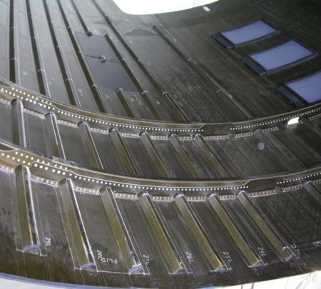
12 2-Plate Specimen Description BMS (T800H/#3900-2) unidirectional pre-preg tape BMS peel ply Titanium Fasteners (0/45/90/-45) 3S (0/-45/02/90/45/02/-45/90/45/0) S


13 2-Plate Specimen
14 ATP 2
15 ATP 3
16
17 Summary of Test Results Propagation arrestment and stable propagation thereafter demonstrated. Fastener install torque (friction) is a major driver of crack arrest capability. High-stiffness lay-up experience more increase in arrest capability for the same fastener size and torque. Fabrication of thick specimens is difficult. Crack front is not symmetric across the width of the specimen, especially near the fastener.
18 Analytical Solution vs. Experiment Properties used E 1 E 2 G 12 t = psi = psi = psi = in G IIC = 12 in-lb/in 2 Layups (0/45/90/-45) 3S /crack/(0/45/90/-45) 3S (0/-45/0 2 /90/45/0 2 /-45/90/45/0) S /crack/ (0/-45/0 2 /90/45/0 2 /-45/90/45/0) S Fastener Stiffness 30% of Huth s Equation
19 (0/45/90/-45) 3S /crack/(0/45/90/-45) 3S CLT E x = psi Plain Strain E x = psi Strain Gauge E x = psi
20 (0/-45/0 2 /90/45/0 2 /-45/90/45/0) S /crack/ (0/-45/0 2 /90/45/0 2 /-45/90/45/0) S CLT E x = psi Plain Strain E x = psi Strain Gauge E x = psi
21 Future Research Conduct Parametric Studies on Crack Arrest by a Single Fastener Develop Analytical Tool to Study Crack Arrest by Multiple Fasteners Conduct Experiments to Determine the Fastener Arrest Effectiveness using Resin Systems with Different G IC :G IIC Ratios Experimental Investigation of Delamination Propagation with Two Fasteners in Series
22 Delamination Arrest by One and Two Fasteners
23 Simulation of Varying G IC /G IIc Ratios G IC G IIC Ra'o
24 Single Axial Load Vs. Crack Tip Location
25 Summary Technical approach to disbond/delamination arrest features in aircraft composite structures have been presented. Analytical and experimental results on delamination arrest by fastener has been presented. Future research on the delamination arrest by fasteners has been identified.
26 Thanks for Attending Questions? Suggestions? Comments?
27
28


29 Mode II Test Specimen in 3-D 29
30 Analytical Model Crack length pass the fastener Original crack length 30
31 Model Description 16-ply CFRP ( t = x 16 = 0.12 ) Lay-ups Percentage of 0-deg: 25% / 37.5% / 50% / 62.5% Fastener Ti-Al6-V4 (E = 16.5x10 6 psi) d = 0.25 in Fastener Flexibility (H. Huth, 1986) C a t1+ t2 b = d n t1e1 nt2e2 nt1e3 2nt2E3 The Joint Advanced Materials and Structures Center of Excellence
32 Discrepancies and Unknowns Discrepancies CLT E x /Plain Strain E x does not correspond to strain gauge E x Fastener joint has only 30% of the stiffness as predicted by Huth s model Fastener hole begins to crush, and fastener rotates as load increases Unknowns G IIC Contact Friction as a result of install torque
 62.")
33 Results: Applied Moment Only Crack Length vs. Load - Moment Crack Length (mm) % 0-deg 25% 0-deg w/ fastener 37.5% 0-deg 37.5% 0-deg w/ fastener % 0-deg % 0-deg w/ fastener 62.5% 0-deg Moment (N-m) 62.5% 0-deg w/ fastener 33
34 Results: Applied Tension Only Crack Length vs. Load - Tension Crack Length (mm) % 0-deg 25% 0-deg w/ fastener 37.5% 0-deg 37.5% 0-deg w/ fastener 50% 0-deg 50% 0-deg w/ fastener 62.5% 0-deg 62.5% 0-deg w/ fastener Tension (N) 34

35 Friction and Fastener Preload DCB - Equal and Opposite Axial Load Effect of Fastener Preload and Friction 40 Crack Location (mm) No Preload 25% Preload 50% Preload 75% Preload No Preload w/ friction 25% Preload w/ Friction 50% Preload w/ friction 75% Preload w/ friction Normalized Load 35
 30 20 10 1.")
 1 GI GII 0.8 SERR (N/mm) 0.6 0.4 0.")
36 Mode II Test Specimen Preliminary Findings Mode II Test Specimen Crack Location (mm) Mode II Test Specimen Load (N) 1 GI GII 0.8 SERR (N/mm) Crack Tip Location (mm) 36
Development of Reliability-Based Damage Tolerant Structural Design Methodology
 Development of Reliability-Based Damage Tolerant Structural Design Methodology Presented by Dr. Kuen Y. Lin and Dr. Andrey Styuart Department of Aeronautics and Astronautics University of Washington, Box
FRACTURE MECHANICS TEST METHODS
 DEVELOPMENT AND EVALUATION OF FRACTURE MECHANICS TEST METHODS FOR SANDWICH COMPOSITES Dan Adams Department of Mechanical Engineering University it of Utah Salt Lake City, UT AMTAS A t 2012 M ti AMTAS Autumn
Improving Adhesive Bonding of Composites Through Surface Characterization Effect of amine blush on bond quality
 Improving Adhesive Bonding of Composites Through Surface Characterization Effect of amine blush on bond quality Brian Flinn, Greg Iglesias, Alex Stark, Russell Kilgannon Materials Science and Engineering
Composite Damage Material Modeling for Crash Simulation: MAT54 & the Efforts of the CMH-17 Numerical Round Robin
 Composite Damage Material Modeling for Crash Simulation: MAT54 & the Efforts of the CMH-17 Numerical Round Robin 2014 Technical Review Bonnie Wade (UW) Prof. Paolo Feraboli AMTAS (JAMS) Crashworthiness
Module 4 : Deflection of Structures Lecture 4 : Strain Energy Method
 Module 4 : Deflection of Structures Lecture 4 : Strain Energy Method Objectives In this course you will learn the following Deflection by strain energy method. Evaluation of strain energy in member under
Durability of bonded aircraft structure. AMTAS Fall 2016 meeting October 27 th 2016 Seattle, WA
 Durability of bonded aircraft structure AMTAS Fall 216 meeting October 27 th 216 Seattle, WA Durability of Bonded Aircraft Structure Motivation and Key Issues: Adhesive bonding is a key path towards reduced
Application of fracture mechanics-based methodologies for failure predictions in composite structures
 Application of fracture mechanics-based methodologies for failure predictions in composite structures Zoltan Mikulik a, B. Gangadhara Prusty a, Rodney S. Thomson b, Donald W. Kelly a,* a School of Mechanical
14. *14.8 CASTIGLIANO S THEOREM
 *14.8 CASTIGLIANO S THEOREM Consider a body of arbitrary shape subjected to a series of n forces P 1, P 2, P n. Since external work done by forces is equal to internal strain energy stored in body, by
High Fidelity Failure Analysis for A Composite Fuselage Section 1
 High Fidelity Failure Analysis for A Composite Fuselage Section 1 Jian Li Engineer/Scientist, The Boeing Company Mesa, Arizona Jian.Li@Boeing.com Carlos G. Dávila Aerospace Engineer, NASA Langley Research
External Work. When a force F undergoes a displacement dx in the same direction i as the force, the work done is
 Structure Analysis I Chapter 9 Deflection Energy Method External Work Energy Method When a force F undergoes a displacement dx in the same direction i as the force, the work done is du e = F dx If the
Mixed-Mode Fracture Toughness Determination USING NON-CONVENTIONAL TECHNIQUES
 Mixed-Mode Fracture Toughness Determination USING NON-CONVENTIONAL TECHNIQUES IDMEC- Pólo FEUP DEMec - FEUP ESM Virginia Tech motivation fracture modes conventional tests [mode I] conventional tests [mode
STRUCTURAL SURFACES & FLOOR GRILLAGES
 STRUCTURAL SURFACES & FLOOR GRILLAGES INTRODUCTION Integral car bodies are 3D structures largely composed of approximately subassemblies- SSS Planar structural subassemblies can be grouped into two categories
FRACTURE TOUGHNESS OF ADHESIVE BONDED COMPOSITE JOINTS UNDER MIXED MODE LOADING.
 FRACTURE TOUGHNESS OF ADHESIVE BONDED COMPOSITE JOINTS UNDER MIXED MODE LOADING. X. J. Gong, F. Hernandez, G. Verchery. ISAT - Institut Supérieur de l Automobile et des Transports, LRMA - Laboratoire de
Development of Reliability-Based Damage Tolerant Structural Design Methodology
 Development of Reliability-Based Damage Tolerant Structural Design Methodology Dr. Kuen Y. Lin and Dr. Andrey Styuart Department of Aeronautics and Astronautics University of Washington Outline Background
Tensile behaviour of anti-symmetric CFRP composite
 Available online at www.sciencedirect.com Procedia Engineering 1 (211) 1865 187 ICM11 Tensile behaviour of anti-symmetric CFRP composite K. J. Wong a,b, *, X. J. Gong a, S. Aivazzadeh a, M. N. Tamin b
Prediction of Delamination Growth Behavior in a Carbon Fiber Composite Laminate Subjected to Constant Amplitude Compression-Compression Fatigue Loads
 Prediction of Delamination Growth Behavior in a Carbon Fiber Composite Laminate Subjected to Constant Amplitude Compression-Compression Fatigue Loads J. Raju 1*, D.S. Sreedhar 2, & C.M. Manjunatha 1 1
Crashworthiness of composite structures: Experiment and Simulation
 Crashworthiness of composite structures: Experiment and Simulation Francesco Deleo, Bonnie Wade and Prof. Paolo Feraboli (UW) Dr. Mostafa Rassaian (Boeing R&T) JAMS 2010 The Joint Advanced Materials and
Using the finite element method of structural analysis, determine displacements at nodes 1 and 2.
 Question 1 A pin-jointed plane frame, shown in Figure Q1, is fixed to rigid supports at nodes and 4 to prevent their nodal displacements. The frame is loaded at nodes 1 and by a horizontal and a vertical
Composite Fittings. Shear clips Lugs. Large special purpose fitting. Attachment clips
 Composite Fittings L Shear clips Lugs Attachment clips Large special purpose fitting Fittings - General A fitting connects at least two other parts It (hopefully) transfers load effectively at the junction
Deflections and Strains in Cracked Shafts Due to Rotating Loads: A Numerical and Experimental Analysis
 International Journal of Rotating Machinery, 9: 303 311, 2003 Copyright c Taylor & Francis Inc. ISSN: 1023-621X DOI: 10.1080/10236210390147416 Deflections and Strains in Cracked Shafts Due to Rotating
UNIT IV FLEXIBILTY AND STIFFNESS METHOD
 SIDDHARTH GROUP OF INSTITUTIONS :: PUTTUR Siddharth Nagar, Narayanavanam Road 517583 QUESTION BANK (DESCRIPTIVE) Subject with Code : SA-II (13A01505) Year & Sem: III-B.Tech & I-Sem Course & Branch: B.Tech
TESTING AND ANALYSIS OF COMPOSITE SKIN/STRINGER DEBONDING UNDER MULTI-AXIAL LOADING.
 TESTING AND ANALYSIS OF COMPOSITE SKIN/STRINGER DEBONDING UNDER MULTI-AXIAL LOADING. Ronald Krueger*, Michael K. Cvitkovich*, T. Kevin O'Brien**, and Pierre J. Minguet*** * National Research Council Research
SKIN-STRINGER DEBONDING AND DELAMINATION ANALYSIS IN COMPOSITE STIFFENED SHELLS
 SKIN-STRINER DEBONDIN AND DELAMINATION ANALYSIS IN COMPOSITE STIFFENED SHELLS R. Rikards, K. Kalnins & O. Ozolinsh Institute of Materials and Structures, Riga Technical University, Riga 1658, Latvia ABSTRACT
Deflections and Strains in Cracked Shafts due to Rotating Loads: A Numerical and Experimental Analysis
 Rotating Machinery, 10(4): 283 291, 2004 Copyright c Taylor & Francis Inc. ISSN: 1023-621X print / 1542-3034 online DOI: 10.1080/10236210490447728 Deflections and Strains in Cracked Shafts due to Rotating
2012 MECHANICS OF SOLIDS
 R10 SET - 1 II B.Tech II Semester, Regular Examinations, April 2012 MECHANICS OF SOLIDS (Com. to ME, AME, MM) Time: 3 hours Max. Marks: 75 Answer any FIVE Questions All Questions carry Equal Marks ~~~~~~~~~~~~~~~~~~~~~~
Chapter 5 Structural Elements: The truss & beam elements
 Institute of Structural Engineering Page 1 Chapter 5 Structural Elements: The truss & beam elements Institute of Structural Engineering Page 2 Chapter Goals Learn how to formulate the Finite Element Equations
Finite element modelling of infinitely wide Angle-ply FRP. laminates
 www.ijaser.com 2012 by the authors Licensee IJASER- Under Creative Commons License 3.0 editorial@ijaser.com Research article ISSN 2277 9442 Finite element modelling of infinitely wide Angle-ply FRP laminates
Autodesk Helius PFA. Guidelines for Determining Finite Element Cohesive Material Parameters
 Autodesk Helius PFA Guidelines for Determining Finite Element Cohesive Material Parameters Contents Introduction...1 Determining Cohesive Parameters for Finite Element Analysis...2 What Test Specimens
THREE DIMENSIONAL STRESS ANALYSIS OF THE T BOLT JOINT
 THREE DIMENSIONAL STRESS ANALYSIS OF THE T BOLT JOINT Víctor Martínez 1, Alfredo Güemes 2, Norbert Blanco 1, Josep Costa 1 1 Escola Politècnica Superior. Universitat de Girona. Girona, Spain (17071) 2
Lecture 4: PRELIMINARY CONCEPTS OF STRUCTURAL ANALYSIS. Introduction
 Introduction In this class we will focus on the structural analysis of framed structures. We will learn about the flexibility method first, and then learn how to use the primary analytical tools associated
ME FINITE ELEMENT ANALYSIS FORMULAS
 ME 2353 - FINITE ELEMENT ANALYSIS FORMULAS UNIT I FINITE ELEMENT FORMULATION OF BOUNDARY VALUE PROBLEMS 01. Global Equation for Force Vector, {F} = [K] {u} {F} = Global Force Vector [K] = Global Stiffness
2 marks Questions and Answers
 1. Define the term strain energy. A: Strain Energy of the elastic body is defined as the internal work done by the external load in deforming or straining the body. 2. Define the terms: Resilience and
COMELD TM JOINTS: A NOVEL TECHNIQUE FOR BONDING COMPOSITES AND METAL
 COMELD TM JOINTS: A NOVEL TECHNIQUE FOR BONDING COMPOSITES AND METAL F.J. Guild *, P.J. Hogg + and W. Tu School of Engineering and Materials Science, Queen Mary, University of London, London E1 4NS, UK
NUMERICAL INVESTIGATION OF DELAMINATION IN L-SHAPED CROSS-PLY COMPOSITE BRACKET
 NUMERICAL INVESTIGATION OF DELAMINATION IN L-SHAPED CROSS-PLY COMPOSITE BRACKET M.Gümüş a*, B.Gözlüklü a, D.Çöker a a Department of Aerospace Eng., METU, Ankara, Turkey *mert.gumus@metu.edu.tr Keywords:
EFFECTS OF STRAIN ENERGY RELEASE RATE ON DELAMINATION IN TEMPERATURE ENVIRONMENT VENKATA NAGA RAVITEJ SANKARABATLA
 EFFECTS OF STRAIN ENERGY RELEASE RATE ON DELAMINATION IN TEMPERATURE ENVIRONMENT by VENKATA NAGA RAVITEJ SANKARABATLA Presented to the Faculty of the Graduate School of The University of Texas at Arlington
Indeterminate Analysis Force Method 1
 Indeterminate Analysis Force Method 1 The force (flexibility) method expresses the relationships between displacements and forces that exist in a structure. Primary objective of the force method is to
Lecture 8: Flexibility Method. Example
 ecture 8: lexibility Method Example The plane frame shown at the left has fixed supports at A and C. The frame is acted upon by the vertical load P as shown. In the analysis account for both flexural and
Experimental and finite elements study of the behaviour of a double shear bolted joint submitted to tensile and bending forces
 Experimental and finite elements study of the behaviour of a double shear bolted joint submitted to tensile and bending forces K. Koffi', R. Chieragatti', J. Huef & E. Bouchef 1 Department of Mechanical
Supplement: Statically Indeterminate Trusses and Frames
 : Statically Indeterminate Trusses and Frames Approximate Analysis - In this supplement, we consider an approximate method of solving statically indeterminate trusses and frames subjected to lateral loads
IDE 110 Mechanics of Materials Spring 2006 Final Examination FOR GRADING ONLY
 Spring 2006 Final Examination STUDENT S NAME (please print) STUDENT S SIGNATURE STUDENT NUMBER IDE 110 CLASS SECTION INSTRUCTOR S NAME Do not turn this page until instructed to start. Write your name on
COMBINED IN-PLANE AND THROUGH-THE-THICKNESS ANALYSIS FOR FAILURE PREDICTION OF BOLTED COMPOSITE JOINTS
 COMBINED IN-PLANE AND THROUGH-THE-THICKNESS ANALYSIS FOR FAILURE PREDICTION OF BOLTED COMPOSITE JOINTS V. Kradinov, * E. Madenci The University of Arizona, Tucson, Arizona, 8575 D. R. Ambur NASA Langley
LS-DYNA MAT54 for simulating composite crash energy absorption
 LS-DYNA MAT54 for simulating composite crash energy absorption Bonnie Wade and Paolo Feraboli (UW) Mostafa Rassaian (Boeing BR&T) JAMS 2011 The Joint Advanced Materials and Structures Center of Excellence
ID-1274 SPLIT ANGLE-PLY BEAM SPECIMEN FOR MEASUREMENT OF FRACTURE TOUGHNESS WITH MODE III STRESS STATE
 ID-1274 SPLIT ANGLE-PLY BEAM SPECIMEN FOR MEASUREMENT OF FRACTURE TOUGHNESS WITH MODE III STRESS STATE Kunigal Shivakumar, Srikant Ghantae * and Matthew Sharpe Center for Composite Materials Research North
A SELF-INDICATING MODE I INTERLAMINAR TOUGHNESS TEST
 A SELF-INDICATING MODE I INTERLAMINAR TOUGHNESS TEST P. Robinson The Composites Centre, Department of Aeronautics, Imperial College London South Kensington, London, SW7 2AZ, UK p.robinson@imperial.ac.uk
Nonlinear Modeling of Fiber-Reinforced Elastomers and the Response of a Rubber Muscle Actuator
 Nonlinear Modeling of Fiber-Reinforced Elastomers and the Response of a Rubber Muscle Actuator Larry D. Peel, Ph.D.* Department of Mechanical & Industrial Engineering Texas A&M Univ. - Kingsville David
Basic Energy Principles in Stiffness Analysis
 Basic Energy Principles in Stiffness Analysis Stress-Strain Relations The application of any theory requires knowledge of the physical properties of the material(s) comprising the structure. We are limiting
Impact and Crash Modeling of Composite Structures: A Challenge for Damage Mechanics
 Impact and Crash Modeling of Composite Structures: A Challenge for Damage Mechanics Dr. A. Johnson DLR Dr. A. K. Pickett ESI GmbH EURO-PAM 99 Impact and Crash Modelling of Composite Structures: A Challenge
A 3D Discrete Damage Modeling Methodology for Abaqus for Fatigue Damage Evaluation in Bolted Composite Joints
 A 3D Discrete Damage Modeling Methodology for Abaqus for Fatigue Damage Evaluation in Bolted Composite Joints Eugene Fang 1, Ling Liu 1, Michael Stuebner 1, Jim Lua 1 1 Global Engineering and Materials,
COMPRESSIVE BEHAVIOR OF IMPACT DAMAGED COMPOSITE LAMINATES
 16 TH INTERNATIONAL CONFERENCE ON COMPOSITE MATERIALS COMPRESSIVE BEHAVIOR OF IMPACT DAMAGED COMPOSITE LAMINATES Hiroshi Suemasu*, Wataru Sasaki**, Yuuichiro Aoki***, Takashi Ishikawa**** *Department of
If the number of unknown reaction components are equal to the number of equations, the structure is known as statically determinate.
 1 of 6 EQUILIBRIUM OF A RIGID BODY AND ANALYSIS OF ETRUCTURAS II 9.1 reactions in supports and joints of a two-dimensional structure and statically indeterminate reactions: Statically indeterminate structures
CHARACTERIZATION, ANALYSIS AND PREDICTION OF DELAMINATION IN COMPOSITES USING FRACTURE MECHANICS
 Oral Reference Number: ICF100942OR CHARACTERIZATION, ANALYSIS AND PREDICTION OF DELAMINATION IN COMPOSITES USING FRACTURE MECHANICS T. Kevin O Brien U.S. Army Research Laboratory Vehicle Technology Directorate
Static and Time Dependent Failure of Fibre Reinforced Elastomeric Components. Salim Mirza Element Materials Technology Hitchin, UK
 Static and Time Dependent Failure of Fibre Reinforced Elastomeric Components Salim Mirza Element Materials Technology Hitchin, UK Introduction Fibre reinforced elastomers are used in many applications,
Effects of Resin and Fabric Structure
 Fatigue of Wind Blade Laminates: Effects of Resin and Fabric Structure Details David Miller, Daniel D. Samborsky and John F. Mandell Montana State t University it MCARE 2012 Outline Overview of MSU Fatigue
Shafts: Torsion of Circular Shafts Reading: Crandall, Dahl and Lardner 6.2, 6.3
 M9 Shafts: Torsion of Circular Shafts Reading: Crandall, Dahl and Lardner 6., 6.3 A shaft is a structural member which is long and slender and subject to a torque (moment) acting about its long axis. We
Name :. Roll No. :... Invigilator s Signature :.. CS/B.TECH (CE-NEW)/SEM-3/CE-301/ SOLID MECHANICS
/SEM-3/CE-301/ SOLID MECHANICS") Name :. Roll No. :..... Invigilator s Signature :.. 2011 SOLID MECHANICS Time Allotted : 3 Hours Full Marks : 70 The figures in the margin indicate full marks. Candidates are required to give their answers
Name :. Roll No. :..... Invigilator s Signature :.. 2011 SOLID MECHANICS Time Allotted : 3 Hours Full Marks : 70 The figures in the margin indicate full marks. Candidates are required to give their answers
Calculation of Energy Release Rate in Mode I Delamination of Angle Ply Laminated Composites
 Copyright c 2007 ICCES ICCES, vol.1, no.2, pp.61-67, 2007 Calculation of Energy Release Rate in Mode I Delamination of Angle Ply Laminated Composites K. Gordnian 1, H. Hadavinia 1, G. Simpson 1 and A.
Chapter 2: Deflections of Structures
 Chapter 2: Deflections of Structures Fig. 4.1. (Fig. 2.1.) ASTU, Dept. of C Eng., Prepared by: Melkamu E. Page 1 (2.1) (4.1) (2.2) Fig.4.2 Fig.2.2 ASTU, Dept. of C Eng., Prepared by: Melkamu E. Page 2
Lecture 11: The Stiffness Method. Introduction
 Introduction Although the mathematical formulation of the flexibility and stiffness methods are similar, the physical concepts involved are different. We found that in the flexibility method, the unknowns
Open-hole compressive strength prediction of CFRP composite laminates
 Open-hole compressive strength prediction of CFRP composite laminates O. İnal 1, A. Ataş 2,* 1 Department of Mechanical Engineering, Balikesir University, Balikesir, 10145, Turkey, inal@balikesir.edu.tr
Mechanical Behavior of Circular Composite Springs with Extended Flat Contact Surfaces
 Mechanical Behavior of Circular Composite Springs with Extended Flat Contact Surfaces Ping-Cheung Tse epartment of Mechanical Engineering, The Hong Kong Polytechnic University, Hunghom, Kowloon, Hong Kong
Preliminaries: Beam Deflections Virtual Work
 Preliminaries: Beam eflections Virtual Work There are several methods available to calculate deformations (displacements and rotations) in beams. They include: Formulating moment equations and then integrating
STRENGTH AND STIFFNESS REDUCTION OF LARGE NOTCHED BEAMS
 STRENGTH AND STIFFNESS REDUCTION OF LARGE NOTCHED BEAMS By Joseph F. Murphy 1 ABSTRACT: Four large glulam beams with notches on the tension side were tested for strength and stiffness. Using either bending
If the solution does not follow a logical thought process, it will be assumed in error.
 Please indicate your group number (If applicable) Circle Your Instructor s Name and Section: MWF 8:30-9:20 AM Prof. Kai Ming Li MWF 2:30-3:20 PM Prof. Fabio Semperlotti MWF 9:30-10:20 AM Prof. Jim Jones
Review of Strain Energy Methods and Introduction to Stiffness Matrix Methods of Structural Analysis
 uke University epartment of Civil and Environmental Engineering CEE 42L. Matrix Structural Analysis Henri P. Gavin Fall, 22 Review of Strain Energy Methods and Introduction to Stiffness Matrix Methods
ISSN: ISO 9001:2008 Certified International Journal of Engineering Science and Innovative Technology (IJESIT) Volume 2, Issue 4, July 2013
 Volume 2, Issue 4, July 2013") Delamination Studies in Fibre-Reinforced Polymer Composites K.Kantha Rao, Dr P. Shailesh, K. Vijay Kumar 1 Associate Professor, Narasimha Reddy Engineering College Hyderabad. 2 Professor, St. Peter s Engineering
Delamination Studies in Fibre-Reinforced Polymer Composites K.Kantha Rao, Dr P. Shailesh, K. Vijay Kumar 1 Associate Professor, Narasimha Reddy Engineering College Hyderabad. 2 Professor, St. Peter s Engineering
Strength Prediction Of Composite Laminate
 Strength Prediction Of Composite te Prof. Yogananda. A 1, Mr. R. Vijayakumar 2 Assistant Professor, Department of Mechanical Engineering, East West Institute of Technology, Bangalore. Research Scholar,
FASTENER PULL-THROUGH FAILURE IN GFRP LAMINATES
 18 TH INTERNATIONAL CONFERENCE ON COMPOSITE MATERIALS FASTENER PULL-THROUGH FAILURE IN GFRP LAMINATES G. Catalanotti 1*, P.P. Camanho 1, P. Ghys 2, A.T. Marques 1 1 DEMec, Faculdade de Engenharia, Universidade
Slender Structures Load carrying principles
 Slender Structures Load carrying principles Basic cases: Extension, Shear, Torsion, Cable Bending (Euler) v017-1 Hans Welleman 1 Content (preliminary schedule) Basic cases Extension, shear, torsion, cable
A Method for Calculating Strain Energy Release Rates in Preliminary Design of Composite Skin/Stringer Debonding Under Multi-Axial Loading
 NASA/TM-1999-09365 ARL-TR-01 A Method for Calculating Strain Energy Release Rates in Preliminary Design of Composite Skin/Stringer Debonding Under Multi-Axial Loading Ronald Krueger National Research Council
Table of Contents. Preface...xvii. Part 1. Level
 Preface...xvii Part 1. Level 1... 1 Chapter 1. The Basics of Linear Elastic Behavior... 3 1.1. Cohesion forces... 4 1.2. The notion of stress... 6 1.2.1. Definition... 6 1.2.2. Graphical representation...
The numerical simulation research of an Ultra-Light Photovoltaic Cell multilayer composite structure
 5th International Conference on Civil, Architectural and Hydraulic Engineering (ICCAHE 2016) The numerical simulation research of an Ultra-Light Photovoltaic Cell multilayer composite structure Kangwen
QUESTION BANK DEPARTMENT: CIVIL SEMESTER: III SUBJECT CODE: CE2201 SUBJECT NAME: MECHANICS OF SOLIDS UNIT 1- STRESS AND STRAIN PART A
 DEPARTMENT: CIVIL SUBJECT CODE: CE2201 QUESTION BANK SEMESTER: III SUBJECT NAME: MECHANICS OF SOLIDS UNIT 1- STRESS AND STRAIN PART A (2 Marks) 1. Define longitudinal strain and lateral strain. 2. State
Rigid Pavement Mechanics. Curling Stresses
 Rigid Pavement Mechanics Curling Stresses Major Distress Conditions Cracking Bottom-up transverse cracks Top-down transverse cracks Longitudinal cracks Corner breaks Punchouts (CRCP) 2 Major Distress Conditions
Continuum Models of Discrete Particle Systems with Particle Shape Considered
 Introduction Continuum Models of Discrete Particle Systems with Particle Shape Considered Matthew R. Kuhn 1 Ching S. Chang 2 1 University of Portland 2 University of Massachusetts McMAT Mechanics and Materials
Institute of Structural Engineering Page 1. Method of Finite Elements I. Chapter 2. The Direct Stiffness Method. Method of Finite Elements I
 Institute of Structural Engineering Page 1 Chapter 2 The Direct Stiffness Method Institute of Structural Engineering Page 2 Direct Stiffness Method (DSM) Computational method for structural analysis Matrix
CHAPTER 8 SCREWS, FASTENERS, NONPERMANENT JOINTS
 CHAPTER 8 SCREWS, FASTENERS, NONPERMANENT JOINTS This chapter deals with the design and analysis of nonpermanent fasteners such as bolts, power screws, cap screws, setscrews, eys and pins. 8- Standards
PROGRESSIVE DAMAGE ANALYSES OF SKIN/STRINGER DEBONDING. C. G. Dávila, P. P. Camanho, and M. F. de Moura
 PROGRESSIVE DAMAGE ANALYSES OF SKIN/STRINGER DEBONDING C. G. Dávila, P. P. Camanho, and M. F. de Moura Abstract The debonding of skin/stringer constructions is analyzed using a step-by-step simulation
UNIT 1 STRESS STRAIN AND DEFORMATION OF SOLIDS, STATES OF STRESS 1. Define stress. When an external force acts on a body, it undergoes deformation.
 UNIT 1 STRESS STRAIN AND DEFORMATION OF SOLIDS, STATES OF STRESS 1. Define stress. When an external force acts on a body, it undergoes deformation. At the same time the body resists deformation. The magnitude
Ph.D. Preliminary Examination Analysis
 UNIVERSITY OF CALIFORNIA, BERKELEY Spring Semester 2017 Dept. of Civil and Environmental Engineering Structural Engineering, Mechanics and Materials Name:......................................... Ph.D.
STRESS STRAIN AND DEFORMATION OF SOLIDS, STATES OF STRESS
 1 UNIT I STRESS STRAIN AND DEFORMATION OF SOLIDS, STATES OF STRESS 1. Define: Stress When an external force acts on a body, it undergoes deformation. At the same time the body resists deformation. The
Composites: Part B. Analysis of mode I delamination of z-pinned composites using a non-dimensional analytical model
 Composites: Part B 43 (2012) 1776 1784 Contents lists available at SciVerse ScienceDirect Composites: Part B journal homepage: www. elsevier. com/ locate/ compositesb Analysis of mode I delamination of
RATE-DEPENDENT OFF-AXIS COMPRESSIVE STRENGTH OF A UNIDIRECTIONAL CARBON/EPOXY LAMINATE AT HIGH TEMPERATURE
 16 TH INTERNATIONAL CONFERENCE ON COMPOSITE MATERIALS RATE-DEPENDENT OFF-AXIS COMPRESSIVE STRENGTH OF A UNIDIRECTIONAL CARBON/EPOXY LAMINATE AT HIGH TEMPERATURE Masamichi KAWAI *, Satoru SAITO **, Jian-Qi
FATIGUE DESIGN PROCEDURE OF LONGITUDINAL AND TRANSVERSE FUSELAGE JOINTS
 28 TH INTERNATIONAL CONGRESS OF THE AERONAUTICAL SCIENCES FATIGUE DESIGN PROCEDURE OF LONGITUDINAL AND TRANSVERSE FUSELAGE JOINTS Basov V.N. and Dr Pankov A.V TsAGI andrey.pankov@tsagi.ru eywords: fatigue,
k 21 k 22 k 23 k 24 k 31 k 32 k 33 k 34 k 41 k 42 k 43 k 44
 CE 6 ab Beam Analysis by the Direct Stiffness Method Beam Element Stiffness Matrix in ocal Coordinates Consider an inclined bending member of moment of inertia I and modulus of elasticity E subjected shear
Keywords: Adhesively bonded joint, laminates, CFRP, stacking sequence
 THE 19 TH INTERNATIONAL CONFERENCE ON COMPOSITE MATERIALS GLOBAL AND LOCAL INFLUENCE OF STACKING SEQUENCE ON THE STRENGTH OF ADHESIVELY BONDED JOINTS OF CFRP LAMINATES J. Rousseau*, P. Satthamnuwong DRIVE,
University of Bristol - Explore Bristol Research. Early version, also known as pre-print
 Hallett, S. R., & Wisnom, M. R. (2006). Numerical investigation of progressive damage and the effect of layup in notched tensile tests. Journal of Composite Materials, 40 (14), 1229-1245. DOI: 10.1177/0021998305057432
Fracture Behaviour of FRP Cross-Ply Laminate With Embedded Delamination Subjected To Transverse Load
 Fracture Behaviour of FRP Cross-Ply Laminate With Embedded Delamination Subjected To Transverse Load Sriram Chintapalli 1, S.Srilakshmi 1 1 Dept. of Mech. Engg., P. V. P. Siddhartha Institute of Technology.
PREDICTION OF OUT-OF-PLANE FAILURE MODES IN CFRP
 PREDICTION OF OUT-OF-PLANE FAILURE MODES IN CFRP R. R. Pinto 1, P. P. Camanho 2 1 INEGI - Instituto de Engenharia Mecanica e Gestao Industrial, Rua Dr. Roberto Frias, 4200-465, Porto, Portugal 2 DEMec,
1-1 Locate the centroid of the plane area shown. 1-2 Determine the location of centroid of the composite area shown.
 Chapter 1 Review of Mechanics of Materials 1-1 Locate the centroid of the plane area shown 650 mm 1000 mm 650 x 1- Determine the location of centroid of the composite area shown. 00 150 mm radius 00 mm
MAAE 2202 A. Come to the PASS workshop with your mock exam complete. During the workshop you can work with other students to review your work.
 It is most beneficial to you to write this mock final exam UNDER EXAM CONDITIONS. This means: Complete the exam in 3 hours. Work on your own. Keep your textbook closed. Attempt every question. After the
Interlaminar fracture characterization in composite materials by using acoustic emission
 5th International Symposium on NDT in Aerospace, 13-15th November 2013, Singapore Interlaminar fracture characterization in composite materials by using acoustic emission Ian SILVERSIDES 1, Ahmed MASLOUHI
[5] Stress and Strain
![[5] Stress and Strain](/thumbs/95/123344550.jpg "[5] Stress and Strain") [5] Stress and Strain Page 1 of 34 [5] Stress and Strain [5.1] Internal Stress of Solids [5.2] Design of Simple Connections (will not be covered in class) [5.3] Deformation and Strain [5.4] Hooke s Law
[5] Stress and Strain Page 1 of 34 [5] Stress and Strain [5.1] Internal Stress of Solids [5.2] Design of Simple Connections (will not be covered in class) [5.3] Deformation and Strain [5.4] Hooke s Law
AERO 214. Lab II. Measurement of elastic moduli using bending of beams and torsion of bars
 AERO 214 Lab II. Measurement of elastic moduli using bending of beams and torsion of bars BENDING EXPERIMENT Introduction Flexural properties of materials are of interest to engineers in many different
MECHANICAL STRENGTH EXPERIMENTS OF CARBON/CARBON BRAKE DISK
 MECHANICAL STRENGTH EXPERIMENTS OF CARBON/CARBON BRAKE DISK Jae-seok Yoo 1, Dae-un Sung 1, Chun-Gon Kim 1,Chang-Sun Hong 1 and Kwang-Su Kim 2 1 Department of Aerospace Engineering, Korea Advanced Institute
Lecture 7: The Beam Element Equations.
 4.1 Beam Stiffness. A Beam: A long slender structural component generally subjected to transverse loading that produces significant bending effects as opposed to twisting or axial effects. MECH 40: Finite
DYNAMIC DELAMINATION OF AERONAUTIC STRUCTURAL COMPOSITES BY USING COHESIVE FINITE ELEMENTS
 DYNAMIC DELAMINATION OF AERONAUTIC STRUCTURAL COMPOSITES BY USING COHESIVE FINITE ELEMENTS M. Ilyas, F. Lachaud 1, Ch. Espinosa and M. Salaün Université de Toulouse, ISAE/DMSM, 1 avenue Edouard Belin,
3900 PREPREG SYSTEM. Mechanically Stable Mechanical working life of product is over 40 days, allowing for lay-up of large parts.
 PREPREG SYSTEM 3900-series prepregs are highly-toughened 350 F (177 C) cure systems. It is available in a variety of configurations, including unidirectional tape for manual or automated tape laying applications,
MECHANICAL FAILURE OF A COMPOSITE HELICOPTER STRUCTURE UNDER STATIC LOADING
 MECHANICAL FAILURE OF A COMPOSITE HELICOPTER STRUCTURE UNDER STATIC LOADING Steven Roy, Larry Lessard Dept. of Mechanical Engineering, McGill University, Montreal, Québec, Canada ABSTRACT The design and
NUMERICAL MODELLING OF COMPOSITE PIN- JOINTS AND EXPERIMENTAL VALIDATION
 NUMERICAL MODELLING OF COMPOSITE PIN- JOINTS AND EXPERIMENTAL VALIDATION Fabrice PIERRON*, François CERISIER*, and Michel GRÉDIAC** * SMS/ Département Mécanique et Matériaux, École Nationale Supérieure
PDDC 1 st Semester Civil Engineering Department Assignments of Mechanics of Solids [ ] Introduction, Fundamentals of Statics
![PDDC 1 st Semester Civil Engineering Department Assignments of Mechanics of Solids [ ] Introduction, Fundamentals of Statics](/thumbs/92/109382806.jpg "PDDC 1 st Semester Civil Engineering Department Assignments of Mechanics of Solids [ ] Introduction, Fundamentals of Statics") Page1 PDDC 1 st Semester Civil Engineering Department Assignments of Mechanics of Solids [2910601] Introduction, Fundamentals of Statics 1. Differentiate between Scalar and Vector quantity. Write S.I.
Page1 PDDC 1 st Semester Civil Engineering Department Assignments of Mechanics of Solids [2910601] Introduction, Fundamentals of Statics 1. Differentiate between Scalar and Vector quantity. Write S.I.