Design, construction, assembly and testing of ECR proton ion source
|
|
|
- Robyn Shields
- 5 years ago
- Views:
Transcription
1 Chapter 4 Design, construction, assembly and testing of ECR proton ion source In this chapter, the design, fabrication, assembly and testing of three and five electrode ion source is presented. The design of microwave heating system, plasma chamber, magnetic system, extraction system, vacuum system, gas injection system and low conductivity process water system is described in detail. The design parameters of three-electrode ion source that is set up and its present status are shown in Table 4.1. These design beam parameters of the ion source are the input requirement of LEHIPA RFQ. Table 4.1: Parameters of ECR proton ion source. Parameters Design Present status specifications achieved Beam current (ma) Beam energy (kev) Forward RF 2.45 GHz Axial magnetic field (G) Duty factor (%) 100 (CW) 100 (CW) and 1 99 % (pulsed) Gas pressure (10-3 mbar) Emission aperture radius (mm) 8 8 Extraction gap (mm) Proton fraction (%) 80 > 25 kev Beam emittance (π mm-mrad) (rms normalized) kev 59
2 4.1 Microwave system Magnetron The microwave system as shown in Figure 4.1 has been designed using WR-340 and WR-284 waveguide section. The microwave system is sourced by a variable power magnetron (2 kw) at a frequency 2.45 GHz. In CW mode, the microwave generator used was M/S National Electronics make MH2.0W-S microwave head operating at fixed frequency 2.45 GHz, ± 15 MHz and rated output power of 2.0 kw. The microwave head contains a water-cooled magnetron, filament transformer, water connections, launching sections, electrical connections and interlock switches. Output energy is coupled to additional waveguide components or into the cavity/ applicator through a standard WR340 waveguide. A magnetron is a cylindrical high-vacuum diode with a cavity resonator system embedded in the anode. In the presence of suitable crossed electric and magnetic fields, the magnetron produces continuous-wave microwave signals in the GHz frequency bands. The energy available within the cathode/anode zone is coupled out and launched in a waveguide by means of output antenna. The frequency will vary slightly as the output power is varied. A filter network is employed at the magnetron s filament connections to keep all harmonic energy from radiating outside the filament box. The SM745F is the controller for MH2.0W-S that was used to adjust the magnetron s output power level by changing magnetron s anode current through a remote interface connections or through a front panel potentiometer and provides the necessary input power to control the magnetron operation and monitors critical operating parameters of both the magnetron and power supply. The SM745F is a switch mode power supply that uses IGBT technology to generate adjustable, low ripple anode current in a compact enclosure. The SM745F is designed for an input voltage of 230 Vac, 50/60 Hz. 60
![The magnetron was tested up to full power level of 2 kw on a dummy load on a test bench as shown in Figure 4.1 [61]. (a) (b) Figure 4.1 (a) Microwave system on test bench (b) output power calibration.](/docs-images/85/91730170/images/3-0.jpg "For pulsed mode operation M/S SAIREM make GMP20K microwave generator (Figure 4.2) was used that operates at frequency 2.45 GHz ± 25 MHz and maximum output power of 2 kw.")
3 The magnetron was tested up to full power level of 2 kw on a dummy load on a test bench as shown in Figure 4.1 [61]. (a) (b) Figure 4.1 (a) Microwave system on test bench (b) output power calibration. For pulsed mode operation M/S SAIREM make GMP20K microwave generator (Figure 4.2) was used that operates at frequency 2.45 GHz ± 25 MHz and maximum output power of 2 kw. In pulsed mode the magnetron can be operated in the frequency range from 2.5 khz to 250 MHz and the duty cycle between 1 to 99%. The rising and falling time of the pulse is about 100 μs. 61

4 Figure 4.2 Pulsed microwave generator and circulator Circulator The circulator used in the microwave transmission section was a ferrite loaded 3-port device, which allows power flow from the power source to the load, but prevents reflected power from reaching the magnetron and thus protect it from damage. Reflected power will cause overheating of the cathode and anode, resulting in shortened magnetron life or catastrophic failure. The reflected power is diverted into the dummy load. The benefits of using circulators include increased power stability, longer magnetron life, increased efficiency, increased equipment reliability and thus lower overall cost. The circulator suitable for the National-make magnetron MH2.0W-S is the WR284CIRC3A that was used to handle an average power of 3 kw at 2.45 GHz. It provides an isolation of 20 db, with VSWR of
5 4.1.3 Dual directional coupler, power sensor and power meter A dual directional coupler of M/S GERLING make GA310 was used to measure the forward and reflected powers simultaneously. In this case, a 2-hole directional coupler was used, where the primary waveguide is coupled to a secondary waveguide by means of suitable apertures. The power sensing probe used in the coupler consists of a loop antenna mounted above a short section of waveguide and coupled to the waveguide through a round iris. One end of the loop is terminated with a 50 Ω RF resistor in a proprietary mount. This construction is important to the directivity of the coupler (ability to distinguish between forward and reverse signals). The other end of the loop delivers the attenuated output signal to the female N type connector. The coupling iris is sized and the loop position adjusted to achieve the desired coupling factor. The coupling factor for GA310 is 60 db ± GHz, directivity 23 db and output connector 50 Ω N type female. The forward and reflected power from directional coupler was measured using M/S Agilent E-Series E9323A peak and average power sensors and EPM-P series E 4417 A peak and average power meters (Figure 4.3). The sensors have two independent measurement paths, the default normal path for continuously sampled measurements of modulated signals and the time gated measurements. The frequency, bandwidth and power range of E9323A sensor is 5 MHz, 50 MHz to 6 GHz, -60 dbm to + 20 dbm (average only mode) and - 40 dbm to + 20 dbm (normal mode) respectively. The average only path is suitable for average power measurement of continuous wave (CW). Power measurement includes peak, peak-to-average ratio and average power of RF and microwave signals. The power meter has extensive triggering features such as continuous, level, external TTL, and GPIB for making time gated measurements. 63
 and RI1567 auto tuner controller was used for waveguide to plasma impedance matching.")
6 Figure 4.3 RF power meter and power sensors Four stub auto tuner The M/S SAIREM makes AI4SAWR340 four stubs microwave auto tuner (Figure 4.4) and RI1567 auto tuner controller was used for waveguide to plasma impedance matching. The four stub automatic matching tuner is a waveguide component whose role is to reduce automatically the microwave reflected power that may be created by low absorbing load, a poorly matched monomode or multimode cavity etc. The AI4S is integrated in one single unit. The impedance sensors, the four tuning stub and the electronic control system, all mounted on the WR340 waveguide. The normal operating of AI4S is between the microwave generator and the load. In principle, as soon as the microwaves are generated, the autotuner matches instantaneously the load and maintains 64

7 permanently the reflected power at zero watts. The maximum travelling time of the stubs (from maximum mismatch to full match) is six seconds. The operating frequency of autotuner is 2.45 GHz and the maximum operating power is 6 kw. Figure 4.4 Four stub auto tuner and directional coupler DC waveguide break A 50 kv dc waveguide break as shown in Figure 4.5 has been designed and fabricated so that all the active elements of the microwave power supply are at ground potential. The break consists of a 3mm thick sheet of Teflon clamped between a choke flange and a standard flange by two acrylic plates. When TE 10 mode wave travels in the rectangular waveguide, the most intense wall current along the waveguide axis flows near the center of the wider walls. Therefore, the choke flange is designed so that the waves from near the center of the wider walls are most effectively chocked. 65
 the distances from A to B and from B to C are one-fourth the microwave wavelength.")
8 Perspex flange Choke flange Teflon disc Wave guide flange C B A Wave guide WR-284 Wave guide WR-284 (a) (b) Figure 4.5 (a) Schematic and (b) fabricated DC waveguide break. In Figure 4.5 (a) the distances from A to B and from B to C are one-fourth the microwave wavelength. In this structure the microwave traveling from point A to the recess passes through point B and is reflected at point C to perform a standing wave corresponding to incoming waves. At point B, no current flows at the wall surface because the quarter wavelengths distance between points B and C. Therefore, there is no fear of microwave leakage from point B through the gap in which the insulator is inserted. The design of the waveguide break was carried out using 3D calculation. The model and the S 11 parameter are shown in Figure 4.6 (a) and (b). 66

9 (a) (b) Figure 4.6 (a) 3 D model of waveguide break and (b) S 11 parameter Double ridge waveguide In order to optimize the coupling between the microwave generator and the plasma chamber a four section quarter-wavelength long ridges [62, 63] also known as quarter wave transformer (binomial type), was inserted immediately ahead of the microwave window. The purpose of the ridges is to match the impedance of a WR284 waveguide working in the dominant mode (TE 10 67
10 mode) to the equivalent impedance of the plasma. The double ridge waveguide developed inhoused was used for (1) optimizing the coupling between the microwave generator and the plasma chamber that realizes a progressive match between the impedance of waveguide and impedance of plasma chamber and (2) concentrating the electric field at the chamber axis to maximize the resonance field.. The overall result will be a significant increase in ion current density. The ridge realizes a progressive match between the two impedances Z 0 and Z 5 (Figure 4.7). A four-section quarter wave transformer was designed to get an improved bandwidth compared to a single-section for a given load impedance. These transformers are of two types (1) Binomial/maximally-flat design and (2) Chebyshev/equi-ripple design. Here, only Binomial transformer is considered for design. In binomial transformers, the response will be as flat as possible near the design frequency. The design approach of double ridge waveguide is to match the impedance of WR 284 waveguide of 336 Ω to plasma impedance of ~ 50 Ω. The dimension of WR 284 waveguide is 2a 1 = cm, 2b 1 = 3.4 cm and a 2 = 3.6 cm (Figure 4.7). The calculated impedances of various sections are given in appendix I and the results are summarized in Table (4.2), where index n varies from 1 to 5. 68
11 > > > > > WR284 Figure 4.7 Schematic of double ridge waveguide 69
12 Table. 4.2: Design parameters of double ridge waveguide Item a 2 (cm) 2b n (cm) λ g /4 (cm) Z 0f (Ω) b n /b 1 WR Section I Section II Section III Section IV The design of the ridge waveguide was carried using 3 D calculation. The scattering parameter S 11 is shown in Figure 4.8. The 2D E-field of the distribution on the input and output port of the ridge waveguide is shown in Figure 4.9. There is a field enhancement factor of 1.5. Figure 4.8 Reflection coefficients S 11 as a function of frequency. 70
 inlet and (b) outlet")
13 (a) (b) Figure 4.9 Field pattern of (a) inlet and (b) outlet port of ridge waveguide. 71

14 The fabricated double ridge wave guide made in OFHC copper is shown in Figure Figure 4.10 Fabricated double ridged waveguide Microwave window The microwave window was introduced between the plasma chamber that is at low pressure and the microwave transmission components that are at atmospheric pressure. The design of the dielectric microwave window is very critical in order to realize longer lifetime and higher ion current. Most of the microwaves absorbed by the ECR plasma are right hand circularly polarized microwaves. The dielectric constant ε p of the plasma for these waves, along the static magnetic field, is given by ε p = 1- [( pe / RF ) 2 /(1- ce / RF )] (4.1) 72

15 The dielectric constant becomes larger as the plasma density becomes higher. Therefore, the microwaves are expected to produce a strong reflection from the high-density plasma. The multilayer dielectric plates are useful for reducing this reflection if the thickness and the dielectric constant of the plates are optimized [64]. In our design a two-layer window was used to introduce the microwave in the plasma chamber. The first layer is 6mm thick quartz plate as shown in Figure 4.11 (M/S GERLING make, waveguide: WR 284, waveguide flanges: CPR284, operating frequency: 2.45 ± 50 MHz, maximum input power: 3 kw, input VSWR: 1.2 (max), Insertion loss: 0.15 db (max)) terminating the waveguide creates a vacuum sealing plate and impedance matching plate. The second layer, a 2.0mm thick boron nitride plate (M/S Morgan Advance Ceramic make) adjacent to the plasma, will conduct away heat generated by electrons backstreaming from the extraction column. Figure 4.11 Microwave quartz vacuum window. 73
16 4.1.8 Solenoid coils and power supplies The magnetic field is required in all high current ion sources to confine the plasma and enhance the ionization rate per electron and for ECR ion source it also enhance power absorption through ECR coupling. The magnetic field required to satisfy ECR resonance condition is B = 2 π f m / e, where f = microwave frequency in (Hz), m = mass of the electron (kg), and e = electronic charge (C). The resonant magnetic field corresponding to microwave frequency of 2.45 GHz is 875 G. The required magnetic field was produced by two solenoid coils enclosed on three sides by magnetic yokes. The design parameters of solenoid coils are shown in Table 4.3. The solenoid coils were designed using magneto-static 2 D and 3 D calculations. The field contour is shown in Figure 4.12 (a) and (b) and 3D model and field arrows are shown in Figure 4.13 (a) and (b). The simulated and measured field is shown in Figure The fabricated solenoid coil is shown Figure 4.15 (a) and the coil enclosed in yoke is shown in Figure 4.15 (b). The coils were energized by two high current DC power supplies in Figure 4.16 of ratings: a) current range: A, voltage range: 0 10 V and maximum power 8 kw. The power supply has line and load regulation < 0.5 ppm and stability ± 10 ppm for eight hours. The solenoid coils placed around the plasma chamber produces the necessary magnetic field for ECR resonance condition. It can be seen from Figure 4.14, that two ECR zone exits, one located near the microwave window and the other located close to the plasma electrode. It has been reported [56] that the source efficiency increases in the presence of two ECR zones. The magnetic induction field in Figure 4.14 is more or less constant and more than 875 G in the middle region of the plasma chamber so that the plasma is confined. If the magnetic field drop significantly anywhere between the point where the plasma is generated and the point where the 74
17 ions are extracted, the plasma will diffuse along the diverging magnetic field lines, proportionately reducing the density at the extraction aperture. Table 4.3: Solenoid coil parameters Coil Parameters Design values Coil type Water cooled ID of the coil (mm) Ф 200 OD of the coil (mm) Ф 300 Length of the coil (mm) 50 Conductors dimension (mm) Size Central hole 7 7 Square OFHC copper Ф 4 Total number of pancakes 3 Ampere-turns (NI) Total resistance of the coil (Ohms) 0.01 Voltage drop (Volts) 7.1 Total power dissipation (kw) 5 Number of water circuit 3 Pressure drop (kg/cm 2 ) 3 Temperature increase ( 0 C) 10 Water flow per circuit (lit/min) 6 75
")

 3D Model of")
 field arrows in")
18 (a) (b) Figure 4.12 Simulated (a) field lines and (b) field contours in two coils. Figure 4.13 (a) 3D Model of solenoid coils and (b) field arrows in two coils. 76
 Figure 4.")
 water- cooled solenoid coil in pancake winding and (b)")
19 Axial Magnetic Field (G) simulated measured Axial Distance (cm) Figure 4.14 Simulated and measured axial magnetic field. (a) (b) Figure 4.15 Fabricated (a) water- cooled solenoid coil in pancake winding and (b) coil enclosed in yoke. 77
 and (b).")
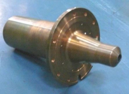
20 Figure 4.16 Solenoid coils power supplies. 4.2 Plasma chamber The plasma chamber in the ion source couples microwave power to plasma and confine plasma. The dimensions of plasma chamber are 90 mm diameter and 100 mm length and made of SS304L and OFHC copper as shown in Figures 4.17 (a) and (b). One end flange of the cylindrical plasma chamber was connected to the ridge waveguide that was sealed for vacuum. Also welded on the end flange was a gas feed line. The microwave input to plasma chamber was provided through the ridge waveguide. The other end of the plasma chamber has an end plate with an 8 mm diameter exit aperture for ion extraction. The magnetic coils were situated on axis 78
 Plasma chamber fabricated in SS 304 L and (b) OFHC copper. The mechanism of microwave power absorption for the maintenance of ECR microwave plasma is not completely understood.")
 wave can dissipate in the ECR heating.")
21 about the both ends enclosing the plasma chamber and were positioned such that resonant field of 875 G exits at both ends. (a) (b) Figure 4.17 (a) Plasma chamber fabricated in SS 304 L and (b) OFHC copper. The mechanism of microwave power absorption for the maintenance of ECR microwave plasma is not completely understood. The widely accepted approach to the analysis of ECR type plasma is based on the perception that the presence of one or (two) ECR zones (B = B ce ) in the plasma chamber provides the complete microwave power absorption. However, it is well known that only right-hand polarized (RHP) wave can dissipate in the ECR heating. The wave with opposite polarization left hand polarized (LHP) wave cannot be absorbed in plasma. But the ECR over dense plasma without detectable microwave leakage and with high degrees of microwave power absorption, P a /P i = (P i P r )/P i > 95% were reported [65-70]. Where P i, P r and P a are incident, reflected and absorbed microwave power in plasma. These experimental results could be explained only if there is effective mechanism (s) that stops microwave propagation downstream and provides a very high level of microwave power absorption of both LHP and RHP waves. One possible interpretation of efficient absorption of linearly polarized waves entering the over dense ECR type plasma is based on the experimentally observed transformation of LHP 79
22 and RHP waves into short wavelength plasma waves which strongly attenuate in Landau damping. It occurs at sites where the plasma density is close to n cr and the angle between the magnitude of field strength, B and the wave propagation direction is small. The presence of resonance magnetic field ω ce = 875 G increase the plasma density to its critical value of n cr = cm -3, results in high level of absorption of microwave power (up to 95-98%). The transition to this region was accompanied with the decrease of reflected microwave power P r and transmitted microwave power P t. Microwave power absorption can occur at any place where the axial magnetic field is ~ 875 G and the plasma density is equal to n cr ( plasma resonance ). The length of the plasma absorption area known as ECR region is dependent on the axial magnetic field gradient db z /dz and has few mm lengths. Plasma electrons gain energy from electromagnetic waves within this area, so electron temperature reached values ev that results in high ionization efficiency. This forms plasma region of very high densities (n e > cm -3 ) even at gas pressures as low as mbar. The length and the configuration of this region depends on the microwave field structure, microwave power, magnetic field configuration, pre-absorption plasma density shape, gas type and pressure, and plasma chamber geometry. The microwave electric power absorbed in plasmas is ultimately dissipated as radiation, heating the gas molecules, due to particle loss at the chamber wall surface and others. Finally, the input power should be equal to the dissipated power, and as a result in steady state the plasma parameters are stabilized. Radiation loss and heating loss are proportional to the plasma volume, and particle loss is proportional to the surface area of the chamber. The steady state density profile of the plasma is regulated by the microwave mode pattern TE r,θ in the r and θ directions. 80
23 In the plasma chamber, the hydrogen plasma so formed consists both positively and negatively charged particles in approximately equal proportions along with unionized neutrals. In case of hydrogen, H and H 3 ions invariably exists in the extraction beam of proton ion source, and their yields sufficiently depends on operational parameters. There are several production processes for H + + +, H 2 and H 3 given as (E th is the threshold energy of the reaction) [71], H 2 + e 2H + e E th = 9.2 ev, (4.2) H + e H + +2 e E th = 13.6 ev, (4.3) + H 2 + e H 2 + e E th = 15.6 ev, (4.4) + H 2 + e H + + H + e E th = 12.1 ev, (4.5) + Or H 2 + e 2H + +2e E th = 17 ev, (4.6) + + H 2 + H 2 H 3 + H E th ~ 0 ev, (4.7) + H 3 + e H + H 2 + e E th = 9.2 ev. (4.8) During discharge, H + produced mainly by two multiple collision processes (4.2), (4.3) and (4.5), (4.6), H is created by direct ionization process (4.4) of hydrogen molecule while H 3 is produced by the dissociative attachment reaction (4.7) in a 2.45 GHz ECR ion source as the average electron temperature in the volume is about several ev. With lower electron temperature in plasma, process (4.3) will predominate the generation of H + ; with increase in electron + temperature, the contribution from process (4.4) for production of H 2 increases. These physical processes are much related to the electron behaviors, so the electron density and temperature of plasma will obviously influence the final extracted beam. 81
24 In order to enhance proton fractions in processes (4.3), (4.5) and (4.6), a 2 mm thick boron nitride (BN) plate was placed at two extremities of the plasma chamber i.e. near the microwave window and near the extractor electrode. The nitride plate reduces the recombination processes for the formation of molecular ions. Moreover, due to high secondary electron emission coefficients of nitride plate, the electron density in the ECR discharge is enhanced leading to increased dissociative ionization of the hydrogen. 4.3 Vacuum system and gas feeding system The vacuum chamber and the associated components of the ion source were fabricated using stainless steel 304 L. The vacuum chamber has four ports. These ports were used for connection to pump, to plasma chamber, view port, pressure gauge and Faraday cup. All the vacuum components were electro-polished and helium leak tested. The leak rate was better than mbar-lit/sec. The objective of the vacuum system is to evacuate the plasma chamber, extractor chamber, diagnostics chamber and other vacuum components to avoid loss of beam particles due to recombination, scattering and to avoid the electrical breakdown due to high voltage. The vacuum system was designed to achieve ultimate base vacuum pressure better than mbar without gas load and to obtain a pressure of the order of 10-3 mbar in plasma chamber, 10-5 mbar in extractor chamber with gas load. A first order estimation of pumping capacity required to evacuate the ion source with and without gas load is given in appendix II. The schematic of vacuum system connected to vacuum diagnostic chamber of ion source is shown in Figure It consists Turbo-molecular Pump (TP), Dry roughing Pump (DP), Gate valve (GV), Angle valve (AV), combined penning-pirani gauges (VPG) and capacitance gauges (VGC). The ultimate vacuum requirement is better than mbar. Turbo molecular pump 82
25 TPH 2301of M/S Pfeiffer make, with the hydrogen pumping capacity of 2000 lit/s, and a dry roughing pump RevoDry 50 P of M/S Pfeiffer make with pumping capacity 50 lit/min (Figure 4.19 (a) and (b) was selected by considering gas throughput ( mbar lit/s) to maintain a pressure of the order of mbar in plasma chamber, mbar in extractor chamber, and to get hydrocarbon free clean vacuum. The pressure difference in the plasma chamber and the extractor chamber was due to the fact that the plasma chamber was evacuated through the 8 mm hole in the plasma electrode. The vacuum gauges used for measuring pressures were capacitance diaphragm gauge heads CMR 263, 264 and compact full range cold cathode gauge head PKR 251 with TPG 256A maxi gauge controller and display unit of M/S Pfeiffer make. The vacuum diagnostic chamber is shown in Figure The gas flow rate was measured with flow meters connected to the leak valve. The ion source was installed on non-magnetic stainless steel support with xyz adjustment for ease of installation and alignment. The schematic gas feeding system of the ion source is shown in Figure The gas feeding system consists of high purity hydrogen gas cylinder, a pressure regulator, shutoff valves, precision leak valve EVN 116 of M/S Pefiffer make and a flow meter to measure and control the gas flow in plasma chamber. As the hydrogen gas reservoir, flow meter and pressure sensor were kept at ground potential, it is isolated by polyethylene tube from the plasma chamber, leak valve and shutoff valve that were floated at 50 kv for ion extraction. The plasma chamber and the extractor geometry were isolated from the solenoid coils which were at ground potential using a polypropylene tube. The extraction geometry was connected to the plasma chamber flange. The end flange of extractor geometry was connected to vacuum chamber. Two alumina rings of 35 cm inner diameter and 7 cm length were used to hold the 50 kv high voltages. 83
, Dry roughing pump (DP), Gate valve (GV),")
. (a) (b) Figure 4.")
26 Figure 4.18 Schematic of vacuum system of ion source. Turbomolecular pump (TP), Dry roughing pump (DP), Gate valve (GV), Angle valve (AV), combined penning-pirani gauges (VPG) and capacitance gauges (VGC). (a) (b) Figure 4.19 (a) Turbo-molecular pump and (b) dry roughing pump. 84


27 Figure 4.20 Vacuum diagnostic chamber. Figure 4.21 Schematic of gas feeding system 85
28 4.4 Extraction electrodes and high voltage power supplies The extraction process basically consists of applying a high voltage between an ion reservoir and a perforated acceleration electrode. The trajectories of the accelerated ions, which determine the beam quality, are influenced by several factors, such as the applied field strength, the shape of the emitting surface, and also on the space charge density of the resulting beam itself. In the case of plasma sources, the shape of the emitting surface (meniscus) depends on the electrical field distribution and the local densities of plasma ions, electrons, and accelerated ions. The meniscus is convex, when the plasma density is relatively high. It is plane under intermediate conditions and concave when the plasma density is low or, if the extraction field is higher. Ion sources using single circular aperture in their extraction electrodes are generally used to obtain low divergence beam. The ion optics of the extraction electrode system in simple terms can be considered that the total beam divergence is the sum of two effects. First the ions are emitted from a curve plasma boundary and collected on a curve extraction electrode, as a result the ion converse towards this electrode. Second the ion diverges as they pass through the aperture in the extraction electrode, this aperture being an electrostatic lens. The factors that determines the residual divergence are; (1) optical aberration in beam forming system due to (a) distortion of plasma boundary due to the use of plasma electrodes of finite thickness (b) nonuniformity of plasma density across the electrode aperture; (c) distortion of the field at the plasma due to the aperture in the second electrode; and (d) aberrations in the electrostatic lens of the second electrode aperture; (2) finite temperature of ions at the plasma boundary giving a finite transverse energy; (3) space charge expansion after extraction. The final divergence angle of a beam extracted from an aperture of radius r is a combination of initial focusing from a concave plasma meniscus with radius R M, focusing from the plasma 86

29 Figure 4.22 Schematic of ion extraction system. electrode inclined at an angle θ, defocussing from the gap g in the extraction electrode, and defocusing due to space charge as shown in Figure The extraction potential which tends to penetrate through the plasma electrode aperture is repelled by the plasma sheath potential; so an equipotential is formed which defines a curve boundary: the plasma meniscus. The relative strength of the plasma and extraction potentials defines the radius of curvature of the meniscus and hence on the current density within the plasma. For an uniform emission from an infinite plane, the Child-Langmuir law [21, 22] gives the current density, J, of singly ionized hydrogen gas as: J = 1.74 (V 3/2 /d 2 ) ma mm -2 (4.9) where V is the applied extraction potential in kv and d is the separation between the aperture and the extraction electrode in mm. For emission from a concave surface with radius of curvature R M, as in Figure 4.22, for small values of d/r M it can be shown that the Eq. (4.9) is multiplied by a factor [71, 72]: 87
30 [1 1.6 d/r M ], (4.10) which is smaller than unity. The total beam current is found by multiplying the current density by area of the emission aperture. For circular aperture of LEHIPA ion source, the current is: I = Jπr 2 = 1.74 (πr 2 /d 2 ) V 3/2 [1-1.6 d/r M ] ma, (4.11) The Perveance P, of an ion beam is defined as: P = I/V 3/2 = [1-1.6 d/r M ] P 0 ma kv -3/2 (4.12) which from Eq. (4.12), is a function of the geometry of the system. The perveance and hence the current of a beam from a concave surface is smaller than the planer perveance, P 0. However the concave meniscus focuses the beam, reducing its divergence. Therefore a balance has to be made between a high extracted current and a low divergence by precisely shaping the plasma meniscus [71]. When this requirement is fulfilled, the extraction system perveance is matched. The overall divergence, ω, of the beam emerging from the extraction system is given by: ω = 290 (r/d) [ P/P 0 ] mrad, (4.13) when P = 0.47 P 0, ω = 0. Inserting this into Eq. (4.12) implies that the perveance match occurs when R M = 3.02 d. Using this value in Eq. (4.11) gives an expected beam current of 50 ma for V = 50 kv, r = 4 mm and d = 17 mm of the LEHIPA ion source. A series of simulation studies were made in order to determine optimum condition for extraction of space charge dominated proton beam extracted from LEHIPA ion source. The curvature of the plasma emission surface tends to converge/diverge during extraction of ion beam. Highest quality beams result whenever the plasma-emission boundary is concave and has an optimum radius of curvature. The optimum radius of curvature can be achieved by carefully 88
31 balancing the plasma density in relation to the strength of the electric field. Under this condition the angular divergence is minimum. To optimized the extraction system some critical points to be considered: 1) matching the current required by adjusting the plasma electrode aperture and the current density which is directly connected to microwave power injected in the source, 2) matching the emittance requirement by optimizing the plasma electrode shape and varying the accelerating field and 3) minimizing the electric field peak value to avoid breakdown by carefully smoothing electrode shape. To achieve high beam current transport after extraction it is necessary that the beam ionizes residual gas in the vacuum chamber and become neutralized by the produced electrons. To avoid back streaming electrons being accelerated back into the source and damaging the source, a suppressor electrode with negative potential is inserted into the extractor system. Downstream this location, the beam space charge is partially compensated by those electrons. The extraction system was designed and optimized to minimize beam size and divergence. The three and five electrode extraction was designed and fabricated for ion extraction. The geometrical parameter of the three and five electrode extraction is shown in Table 4.4 and 4.5. The electrical potential distribution of three electrode and five electrode extraction is shown in Figure The design parameters of the three and five electrode extraction geometry viz. electrode apertures, electrode gaps and electrode shapes were optimized to reduce beam divergence and emittance using beam trajectory simulation software PBGUNS and IGUN. The space charge effect of the beam is incorporated in the code. Figures 4.24 and 4.25 shows the beam extraction electrodes, equipotentials, and trajectories for the actual three and five electrode geometry 89
32 obtained from PBGUNS and IGUN simulations for the injected current density of 995 A/m 2. The emittance plot of three and five electrode ion source is shown in Figure Table 4.4: Geometrical and Electrical parameters of the three-electrode extractor. Parameters Designed values Plasma electrode (PE) aperture diameter (mm) Ф 8 Suppressor electrode (SE) aperture diameter (mm) Ф 13 Ground electrode aperture (GE) (mm) Ф 13 Angle on PE, SE and GE 45 0, 56 0, 56 0 Gap between PE and SE (mm) 17 Gap between PE and GE (mm) 23 Material of the electrodes SS 304 L Insulator Alumina ceramic PE potential (kv) + 50 kv AE potential (kv) - 2 to - 4 kv Table 4.5: Geometrical and electrical parameters of the five-electrode extractor. Parameters Designed values Plasma electrode (PE) aperture diameter (mm) Ф 8 Puller electrode (PUE) aperture diameter (mm) Ф 13 First Ground electrode aperture (FGE) (mm) Ф 13 Suppressor electrode (SE) aperture diameter(mm) Ф 13 Second Ground electrode (SGE) aperture diameter (mm) Ф 13 Angle on PE, PUE, FGE, SE and SGE 45 0, 77 0, 56 0, 56 0, 56 0 Gap between PE and PUE (mm) 9 Gap between PE and FGE (mm) 18 Gap between PE and SE (mm) 27 Gap between PE and SGE (mm) 36 Material of the electrodes OFHC copper Insulator Alumina ceramic PE potential (kv) + 50 kv PUE potential (kv) + 30 to + 45 kv SE potential - 2 kv to 4 kv 90

 five electrode")
33 (a) (b) Figure 4.23 Electrical potential distribution of (a) three electrode (b) five electrode ion source extraction system. 91

 three and (b) five electrodes")
34 (a) (b) Figure 4.24 PBGUNS simulation of equipotential and trajectories of (a) three and (b) five electrodes ion source extraction system. 92

 three and (b) five electrodes")
35 (a) (b) Figure 4.25 IGUN simulation of equipotential and trajectories of (a) three and (b) five electrodes ion source extraction system. 93
36 (a) (b) Figure 4.26 Emittance plot of (a) three and (b) five electrode extraction. 94
37 The PBGUNS and IGUN codes are widely used to solve the plasma meniscus by matching equipotential inside and outside the plasma region and compute the resultant particle trajectories for steady state beam transport. IGUN self-adjusts the ion extraction current on successive iteration cycles, adjusting the Debye length within the plasma region until the selfconsistent solution for the shape and the location of the plasma meniscus is reached. PBGUNS utilizes a fine mesh region near the plasma emission surface, solving the plasma meniscus by matching the particle trajectories and the resultant space charge density distribution on adjacent mesh positions until the solution converses. These codes have two dimensional capabilities and are useful for simulation of cylindrically symmetric or rectangular slit extraction geometries. In PBGUNS code the electrodes are described by line segments sketched onto a grid. The geometry is defined in axis symmetric terms. The axial magnetic field for the ECR proton ion source is entered by specifying a series of breakpoints along the beam axis. The program then interpolates between these points to give a distribution. It has been observed that the presence of an axial magnetic field did not appear to affect the beam trajectories in the PBGUNS simulations. PBGUNS simulation utilizes a self-consistent solver to define the shape of the ion emission surface at the extraction aperture. PBGUNS require initial ion energies of 2-10 ev with the velocity vector oriented in the direction of beam extraction for the simulation to work. Multispecies beams (such as hydrogen) are interactively specified in PBGUNS during the initial setup. IGUN software calculates the electric fields and the trajectories of charged particles for a given configuration of electrodes, with applied voltages and particle initial conditions. It is a two-dimensional code, suitable for simulating the extraction of positive ions from plasma using ion ray optics, and electrostatic field based on solution of Poisson equation. The code starts with 95
38 mesh independent input data containing coordinates of the electrodes (either axis-symmetric or rectangular, as entered), boundary conditions, number of the electrodes, potential of each electrode, plasma potential, current or plasma density or ion current density, fractions of ion species and or mass, electron and ion temperature etc. The mesh points are generated once potentials are applied to the fixed electrodes. It automatically determines the ion extraction current during successive cycles, by matching the electric field gradient outside and inside of the plasma. This process is repeated until a self-consistent solution of the Poisson equation for a good quality extracted particle beam is determined. The resulting distribution of potential along the beam edge is used to match the Laplace s solution in the region external to the beam that will support the charge flow. The code first check the input file and then provide the interactive colored graphics plots of equipotential lines, beam trajectories, electrode log tables for different ion species, emittance diagrams, beam profiles, surface fields along the beam axis, surface fields along the problem boundary, the data files for all the plots, twiss parameters etc. The ray tracing is simulated by numerical integration and fields are differentiated and interpolated from the previous potential map. It also provides extensive supporting functionality in geometry definition, data recording, visualization etc. Figure 4.27 shows the plot of ion beam current with extraction voltage. The ion beam current increases with the increase of extraction voltage govern by space charge limiting current. Figure 4.28 shows the plot of extracted beam current versus plasma density. The beam current varies more or less linearly with plasma density. For 50 ma beam current the plasma density requirement is cm -3. Figure 4.28 shows the plot of beam current and RMS emittance. For 50 ma beam current the RMS emittance is 25 mm - mrad. It is seen from Figure 4.29 that the RMS emittance increases with increase in beam current. This is because the beam emittance 96
39 I (ma) increases with the space charge forces due to increase in beam current. Figure 4.30 shows the plot of beam RMS emittance versus suppressor voltage. The RMS emittance is minimum for suppressor electrode voltage between - 2 to - 4 kv. Figure 4.31 shows the plot of RMS emittance versus plasma electrode angle. The RMS emittance is minimum for plasma electrode angle of V ext (kv) Figure 4.27 Beam current versus extraction voltage for suppressor electrode voltage -2 kv. 97
40 RMS beam emittance (mm-mrad) I b (ma) n e x (cm -3 ) Figure 4.28 Beam current versus plasma electron density for plasma electrode voltage +50 kv and suppressor electrode voltage -2 kv I (ma) Figure 4.29 RMS beam emittance versus beam current for plasma electrode voltage +50 kv and suppressor electrode voltage -2 kv. 98
41 RMS beam emittance mm-mrad) RMS beam emittance (mm - mrad) V Supp (V) Figure 4.30 RMS beam emittance versus suppressor electrode voltage for plasma electrode voltage +50 kv, suppressor electrode voltage -2 kv and beam current of 50 ma Plasma electrode angle (Degree) Figure 4.31 RMS beam emittance versus plasma electrode angle for plasma electrode voltage +50 kv, suppressor electrode voltage -2 kv and beam current of 50 ma. 99
42 RMS beam emittance (mm-mrad) I (ma), RMS beam emittance (mm-mrad) I RMS emittance Plasma electrode aperture radius (mm) Figure 4.32 Beam current (square dots) and RMS beam emittance (round dots) versus plasma electrode aperture radius for plasma electrode voltage +50 kv and suppressor electrode voltage -2 kv d (mm) Figure 4.33 RMS beam emittance versus acceleration gap d for plasma electrode voltage +50 kv, suppressor electrode voltage -2 kv and beam current of 50 ma. 100
43 Figure 4.32 shows the plot of extracted beam current and RMS emittance versus plasma electrode aperture radius. The extracted beam current increases as r 2, where r is the plasma electrode aperture radius. The RMS emittance is near minimum for plasma electrode aperture radius of 4 mm. Figure 4.33 shows the plot of RMS emittance versus accelerating gap between the plasma electrode and suppressor electrode. The RMS emittance is near minimum for accelerating gap of 17 mm. Based on this analysis the extraction electrodes of three and five electrode ion source were fabricated. The schematic of plasma chamber and extraction electrodes of three electrode ion source is shown in Figure 4.34 to 4.37 and that of five electrodes is shown in Figure 4.38 to The fabricated electrodes are shown in Figure 4.44 (a) and (b). 101

44 23 Y' Ø156.0 Ø90.0 A' SECTION:-A'-A' Figure 4.34 Schematic of water cooled plasma chamber made of SS 304L. 102

45 Figure 4.35 Schematic of plasma electrode made of SS 304L. 103

46 ±0.025 Ø Figure 4.36 Schematic of suppressor electrode made of SS 304 L. 104

47 Ø ± Figure 4.37 Schematic of ground electrode made of SS 304 L. 105

48 Ø Figure 4.38 Schematic of water-cooled plasma chamber made of OFHC copper. 106

49 Ø PART No:2 Fig.9a. Assembly drawing of plasma electrode Figure 4.39 Schematic of plasma electrode made of OFHC copper. 107

50 Part No. 3 Ø Figure 4.40 Schematic of puller electrode made of OFHC copper. 108
")
51 Figure 4.41 Schematic of first ground electrode (water-cooled) made of OFHC copper. 109

52 Figure 4.42 Schematic of second ground electrode made of OFHC copper. 110
 made of")
53 Figure 4.43 Schematic of second ground electrode (water-cooled) made of OFHC copper. 111

")


")

54 Plasma electrode Ground electrode Suppressor electrode (a) Plasma electrode Puller electrode 1 st Ground electrode Suppressor electrode 2 nd Ground electrode (b) Figure 4.44 Fabricated extraction electrodes of (a) three and (b) five electrode ion source. 112
 0 50 kv, 0 100 ma and (2) 0 (-5) kv, 0 100 ma with ± 0.01% voltage and current regulation, 0.")
 0 60 kv, 0 100 ma and (2) 0 (-6) kv, 0 100 ma with ± 0.005% voltage and current regulation, 0. (a) (b) Figure 4.")
55 The extraction electrode power supplies of the ion source are shown in Figure 4.45(a) and (b). The high voltage power supplies of M/S Gamma and M/S Spellman make were used for ion extraction. The M/S Gamma make regulated high voltage DC power supplies are of following specifications: (1) 0 50 kv, ma and (2) 0 (-5) kv, ma with ± 0.01% voltage and current regulation, 0.1% ripple, 0.01% stability and remote control operation via RS 232. The M/S Spellman make power supplies are of following specifications: (1) 0 60 kv, ma and (2) 0 (-6) kv, ma with ± 0.005% voltage and current regulation, 0.1% ripple, 0.01% stability and remote control operation via RS 232. (a) (b) Figure 4.45 High voltage power supplies (a) M/S Gamma (b) M/S Spellman make. 113

56 4.5 Assembly of Three and Five Electrode Ion Source on Test Stand After fabrication of all the components of the three and five electrode ECR proton ion source, the components have been assembled on the test stand [3, 73-76]. For ion source assembly, the vacuum diagnostic chamber was first installed on the support stand and leveled. Then the suppressor and ground electrode were assembled on one of the end flanges. The suppressor and the ground electrode were separated by MACOR insulator that isolates 6 kv of suppressor voltage. Two alumina ceramic insulator rings of 352 mm inner diameter, 374 mm outer diameter and 74 mm length were used to isolate the 50 kv high voltages between plasma electrode and ground electrode as shown in Figure Figure 4.46 Assembly of suppressor electrode and ground electrode on end flange. 114
57 MICROWAVE WINDOW PLASMA CHAMBER EXTRACTOR ELECTRODES CERAMIC INSULATOR MAGNETRON 2.45 GHz, 2kW BI-DIRECTIONAL SOLENOID COILS COUPLER PRECISION FOUR STUB LEAK VALVE CIRCULATOR AUTO TUNER BEAM DIAGNOSTIC CHAMBER 87.6 WAVEGUIDE BREAK WATER-COOLED FARADAYCUP/ BEAM DUMP TURBO PUMP SECTION :- A'A' FRONT VIEW Figure 4.47 Schematic of three electrode ion source. 115

58 Figure 4.48 Assembled three-electrode ion source. PLASMA ELECTRODE PULLER ELECTRODE GROUND ELECTRODE 1 SUPPRESOR ELECTRODE GROUND ELECTRODE 2 LEAK VALVE FARADAY CUP/ BEAM DUMP E BEND MAGNETRON QUARTZ WINDOW WAVEGUIDE BREAK BI-DIRECTIONAL COUPLER FOUR STUB AUTO TUNER CIRCULATOR RIDGE WAVEGUIDE PLASMA CHAMBER SOLENOID COILS TURBOMOLECULAR PUMP PORT Figure 4.49 Schematic of five electrode ion source. 116


59 Figure 4.50 Assembled five electrode ion source on test stand. The plasma chamber was assembled at one end flange of the extractor electrode assembly. The other end flange of extractor assembly was connected to the vacuum diagnostic chamber that was installed on the test bench. The extractor assembly was supported on the test bench using Perspex insulator. The assembly was aligned to an accuracy of 0.2 mm over length of 2m. The turbomolecular pump and dry roughing pump were connected to one of the side ports of the vacuum diagnostic chamber. The vacuum gauges were connected to the port provided in the diagnostic chamber. The whole assembly was then enclosed by blank flanges at two ends and vacuum tested to better than 10-6 mbar. The high voltage test was also performed under vacuum to the voltage up to 60 kv. Two solenoid coils were assembled on the test bench support plate enclosing the plasma chamber. The microwave generator and transmission components were assembled and connected to the plasma chamber with microwave quartz window. The schematic and actual set 117
60 up three electrode ion source is shown in Figures 4.47 and The schematic and actual setup of five electrode ion source is shown in Figures 4.49 and Low Conductivity Process Water System For cooling the ion source components, a low conductivity process water system has been designed, fabricated, installed and commissioned to remove heat dissipation due to joule heating [77]. Low conductivity water (LCW) helps in avoiding corrosion and scaling on heat exchanging surface. It provide water with very low silica content (< 0.01 ppm) and it is well known that the efficiency of the cooling system decreases if there is silica content in cooling water. It also increases the leakage current when used as cooling media at 50 kv potential. Typical values of water characteristics obtained from these systems are: (1) conductivity < 1 μs/cm, (2) total dissolved solids < 1 ppm and (3) ph variation is within The LCW system was used for cooling twenty components of the ion source and was designed for 65 kw heat removals, with pumping capacity 200 lit/min (12m 3 /h). It comprises of makeup water system (demineralized water column) and self-circulation through ion exchange beds (resin column) for improving conductivity (polishing), recirculation pumps, SS-304 storage water tank, flexible tubing connections and instrumentation system. The salient features of the LCW system are: (i) automatic improving conductivity (polishing) of demineralized water if conductivity goes beyond the set limit, (ii) independent make-up water facility from raw water source, (iii) recirculation pumping system to cope with 200 lit/min requirement at 5 kg/cm 2 and (iv) measurement and interlock system with remote signals for processing the ion source subsystem controls. More than 50 m of metallic piping ranging from 1 to 2 and 100 m metallic and nylon braided PVC flexible piping carry the 118
61 treated and cooled demineralized water from recirculation system to various components of the ion source. The piping is made of SS-304 stainless steel. The cooling system parameters are listed in Table 4.6. Table 4.6: Cooling system parameters of ion source Parameters Designed values Cooling power (kw) 65 Inlet Temperature ( 0 C) 30 Volume of demineralized water (liters) 1200 Flow rate of demineralized water (liters/min) 200 Flow rate of chill water (liters/min) 100 Flow rate of polishing and make-up water (liters/hour) 300 Supply pressure (kg/cm 2 ) 5 Pumps 3 Outlet temperature ( 0 C) 35 LCW conductivity (μs/cm) 1 The cooling system has to fulfill three main requirements: reliability and safety, low level of mechanical vibration (db) and temperature stability (within ± 1 0 C). For reliable functioning of the system, a spare recirculation pump has been provided on-line, and both pump work alternately. Safety is ensured in case of leakage, by high sensitivity flow switches on each distribution manifold. Continuous water conductivity monitoring and set limit has been adopted (< 1 μs/cm) using on-line conductivity meter. In order to reduce vibrations, suitable pipe 119
62 diameter has been selected for required flow, so as to keep the water velocity in the piping low (less than 1 m/s). Reinforced concrete foundation with 10 mm thick rubber pad has been used for the pumps to arrest vibration. The cooling system has four loops: (i) primary loop of LCW which extract the heat generated in various sub-systems of the ion source, (ii) secondary loops of soft water which exchanges heat from primary loops through plate type heat exchanger (PHE) and dissipate to chilled water, (iii) DM loops (make-up system) provides an initial charge of LCW which is to be stored in the storage tank through the ion exchanger stage, and (iv) conductivity improving (polishing) system. Figure 4.51 shows the schematic and Figure 4.52 shows the cooling system of the ion source. Figure 4.51 Schematic of low conductivity process water system for the ion source. 120
, activated carbon filter, cation, anion and mixed bed exchange resins.")
63 Figure 4.52 Low conductivity process water system of the ion source. In Figure 4.52, the raw water is initially passed through polyethylene cartridge filter (5 μ size), activated carbon filter, cation, anion and mixed bed exchange resins. When raw water passes through cation exchange resin, all cation from water are captured and H + ions are released. The released H + ions react with OH - released by anion exchanger to from water. Thus all ions or minerals from water are removed by two exchangers. The capacity of each column is 300 lit/h. The deionized water after passing through ion exchanger are stored in SS 304 storage tank of 1200 liters capacity and circulated through fully closed type centrifugal pump, to provide 200 lit/m flow at 5 kg/cm 2 pressure to cool various subsystem of the ion source. Flow-control valves 121
A Multi-beamlet Injector for Heavy Ion Fusion: Experiments and Modeling
 A Multi-beamlet Injector for Heavy Ion Fusion: Experiments and Modeling G.A. Westenskow, D.P. Grote; LLNL J.W. Kwan, F. Bieniosek; LBNL PAC07 - FRYAB01 Albuquerque, New Mexico June 29, 2007 This work has
Huashun Zhang. Ion Sources. With 187 Figures and 26 Tables Э SCIENCE PRESS. Springer
 Huashun Zhang Ion Sources With 187 Figures and 26 Tables Э SCIENCE PRESS Springer XI Contents 1 INTRODUCTION 1 1.1 Major Applications and Requirements 1 1.2 Performances and Research Subjects 1 1.3 Historical
PIP-II Injector Test s Low Energy Beam Transport: Commissioning and Selected Measurements
 PIP-II Injector Test s Low Energy Beam Transport: Commissioning and Selected Measurements A. Shemyakin 1, M. Alvarez 1, R. Andrews 1, J.-P. Carneiro 1, A. Chen 1, R. D Arcy 2, B. Hanna 1, L. Prost 1, V.
arxiv: v2 [physics.acc-ph] 21 Jun 2017
![arxiv: v2 [physics.acc-ph] 21 Jun 2017](/thumbs/96/126775970.jpg "arxiv: v2 [physics.acc-ph] 21 Jun 2017") Pulsed Beam Tests at the SANAEM RFQ Beamline arxiv:1705.06462v2 [physics.acc-ph] 21 Jun 2017 G Turemen 1,2, Y Akgun 1, A Alacakir 1, I Kilic 1, B Yasatekin 1,2, E Ergenlik 3, S Ogur 3, E Sunar 3, V Yildiz
Pulsed Beam Tests at the SANAEM RFQ Beamline arxiv:1705.06462v2 [physics.acc-ph] 21 Jun 2017 G Turemen 1,2, Y Akgun 1, A Alacakir 1, I Kilic 1, B Yasatekin 1,2, E Ergenlik 3, S Ogur 3, E Sunar 3, V Yildiz
Jumbo Cross Beam Ionizer
 Jumbo Cross Beam Ionizer Version 1.0 September 30, 2008 Page 1 of 19 Table of Contents Cross Beam Ionizer... 1 Table of Contents... 2 1.0 Packing List... 3 1.1 Packing List for Cross Beam Ionizer... 3
FLASH CHAMBER OF A QUASI-CONTINUOUS VOLUME SOURCE OF NEGATIVE IONS
 FLASH CHAMBER OF A QUASI-CONTINUOUS VOLUME SOURCE OF NEGATIVE IONS P.A. Litvinov, V.A. Baturin * Institute of Applied Physics, National Academy of Science of Ukraine, 58 Petropavlovskaya St. Sumy, 40030
UPGRADE AND COMMISSIONING OF THE PIAVE-ALPI ECR INJECTOR AT LNL
 UPGRADE AND COMMISSIONING OF THE PIAVE-ALPI ECR INJECTOR AT LNL A. Galatà, M. Sattin, L. Bertazzo, L. Boscagli, S. Contran, A. Dainese, A. Lombardi, D. Maniero, M. Poggi, F. Scarpa, A. Facco, INFN-LNL,
Capacitive Pick-Up Type DB 040
 Capacitive Pick-Up Type DB 040 Tel: (609) 924-3011 Fax (609) 924-3018 www.princetonscientific.com Email: info@princetonscientific.com CAPACITIVE PICK-UP PROBE TYPE DB 040 Application: The capacitive pick-up
Design and numerical simulation of thermionic electron gun
 Design and numerical simulation of thermionic electron gun M.Hoseinzade 1;1), A.Sadighzadeh 1) Plasma Physics and Nuclear Fusion Research School, Nuclear Science and Technology Research Institute, AEOI,
MODELING OF AN ECR SOURCE FOR MATERIALS PROCESSING USING A TWO DIMENSIONAL HYBRID PLASMA EQUIPMENT MODEL. Ron L. Kinder and Mark J.
 TECHCON 98 Las Vegas, Nevada September 9-11, 1998 MODELING OF AN ECR SOURCE FOR MATERIALS PROCESSING USING A TWO DIMENSIONAL HYBRID PLASMA EQUIPMENT MODEL Ron L. Kinder and Mark J. Kushner Department of
The Q Machine. 60 cm 198 cm Oven. Plasma. 6 cm 30 cm. 50 cm. Axial. Probe. PUMP End Plate Magnet Coil. Filament Cathode. Radial. Hot Plate.
 1 The Q Machine 60 cm 198 cm Oven 50 cm Axial Probe Plasma 6 cm 30 cm PUMP End Plate Magnet Coil Radial Probe Hot Plate Filament Cathode 2 THE Q MACHINE 1. GENERAL CHARACTERISTICS OF A Q MACHINE A Q machine
The ISIS Penning H - SPS and Diagnostic Developments at RAL
 The ISIS Penning H - SPS and Diagnostic Developments at RAL D.C. Faircloth 1, A.P. Letchford 1, J. Pozimski 1+2, M.O. Whitehead 1, T. Wood 1, S. Jolly 2, P. Savage 2, M. Haigh 3, J. Morrison 3, I. Yew
Two point charges, A and B, lie along a line separated by a distance L. The point x is the midpoint of their separation.
 Use the following to answer question 1. Two point charges, A and B, lie along a line separated by a distance L. The point x is the midpoint of their separation. 1. Which combination of charges would yield
Transmission Lines. Plane wave propagating in air Y unguided wave propagation. Transmission lines / waveguides Y. guided wave propagation
 Transmission Lines Transmission lines and waveguides may be defined as devices used to guide energy from one point to another (from a source to a load). Transmission lines can consist of a set of conductors,
The Booster has three magnet systems for extraction: Kicker Ke, comprising two identical magnets and power supplies Septum Se
 3.2.7 Booster Injection and Extraction 3.2.7.1 Overview The Booster has two magnet systems for injection: Septum Si Kicker Ki The Booster has three magnet systems for extraction: Kicker Ke, comprising
MARKING SCHEME SET 55/1/MT Q. No. Expected Answer / Value Points Marks Total Marks. Section A
 MARKING SCHEME SET 55//MT Q. No. Expected Answer / Value Points Marks Total Marks Set,Q Set2,Q5 Set,Q4 Section A Set,Q2 Set2,Q4 Set,Q5 Set,Q Set2,Q2 Set,Q Set,Q4 Set2,Q Set,Q2 Set,Q5 Set2,Q Set,Q Set,Q6
Robert A. Meger Richard F. Fernster Martin Lampe W. M. Manheimer NOTICE
 Serial Number Filing Date Inventor 917.963 27 August 1997 Robert A. Meger Richard F. Fernster Martin Lampe W. M. Manheimer NOTICE The above identified patent application is available for licensing. Requests
PH2200 Practice Final Exam Summer 2003
 INSTRUCTIONS 1. Write your name and student identification number on the answer sheet. 2. Please cover your answer sheet at all times. 3. This is a closed book exam. You may use the PH2200 formula sheet
UNIT I ELECTROSTATIC FIELDS
 UNIT I ELECTROSTATIC FIELDS 1) Define electric potential and potential difference. 2) Name few applications of gauss law in electrostatics. 3) State point form of Ohm s Law. 4) State Divergence Theorem.
ELEMENT2 High Resolution- ICP-MS INSTRUMENT OVERVIEW
 ELEMENT2 High Resolution- ICP-MS INSTRUMENT OVERVIEW Inductively Coupled Plasma Mass Spectrometry (ICP-MS) What is a Plasma? - The magnetic field created by a RF (radio frequency) coil produces
Outline of College Physics OpenStax Book
 Outline of College Physics OpenStax Book Taken from the online version of the book Dec. 27, 2017 18. Electric Charge and Electric Field 18.1. Static Electricity and Charge: Conservation of Charge Define
- A spark is passed through the Argon in the presence of the RF field of the coil to initiate the plasma
 THE PLASMA Inductively Coupled Plasma Mass Spectrometry (ICP-MS) What is a Plasma? - The magnetic field created by a RF (radio frequency) coil produces a current within a stream of Argon (Ar) gas, which
Virtual Prototype of a Dielectric Window for High Power Microwave Tubes
 Virtual Prototype of a Dielectric Window for High Power Microwave Tubes Alberto Leggieri, Davide Passi and Franco Di Paolo Università degli Studi di Roma Tor Vergata, Department of Electronic Engineering,
qq k d Chapter 16 Electric and Magnetic Forces Electric charge Electric charges Negative (electron) Positive (proton)
 Positive (proton)") Chapter 16 Electric and Magnetic Forces Electric charge Electric charges Negative (electron) Positive (proton) Electrons and protons in atoms/molecules Ions: atoms/molecules with excess of charge Ions
Chapter 16 Electric and Magnetic Forces Electric charge Electric charges Negative (electron) Positive (proton) Electrons and protons in atoms/molecules Ions: atoms/molecules with excess of charge Ions
POLARIZED DEUTERONS AT THE NUCLOTRON 1
 POLARIZED DEUTERONS AT THE NUCLOTRON 1 Yu.K.Pilipenko, S.V.Afanasiev, L.S.Azhgirey, A.Yu.Isupov, V.P.Ershov, V.V.Fimushkin, L.V.Kutuzova, V.F.Peresedov, V.P.Vadeev, V.N.Zhmyrov, L.S.Zolin Joint Institute
D- Charge Exchange Ionizer for the JINR Polarized Ion Source POLARIS
 D- Charge Exchange Ionizer for the JINR Polarized Ion Source POLARIS V.P. Ershov, V.V.Fimushkin, G.I.Gai, L.V.Kutuzova, Yu.K.Pilipenko, V.P.Vadeev, A.I.Valevich Λ and A.S. Belov Λ Joint Institute for Nuclear
Using a Microwave Interferometer to Measure Plasma Density Mentor: Prof. W. Gekelman. P. Pribyl (UCLA)
") Using a Microwave Interferometer to Measure Plasma Density Avital Levi Mentor: Prof. W. Gekelman. P. Pribyl (UCLA) Introduction: Plasma is the fourth state of matter. It is composed of fully or partially
Using a Microwave Interferometer to Measure Plasma Density Avital Levi Mentor: Prof. W. Gekelman. P. Pribyl (UCLA) Introduction: Plasma is the fourth state of matter. It is composed of fully or partially
Beam dynamics studies of H-beam chopping in a LEBT for project X
 Beam dynamics studies of H-beam chopping in a LEBT for project X Qing Ji, David Grote, John Staples, Thomas Schenkel, Andrew Lambert, and Derun Li Lawrence Berkeley National Laboratory, 1 Cyclotron Road,
An ion follows a circular path in a uniform magnetic field. Which single change decreases the radius of the path?
 T5-1 [237 marks] 1. A circuit is formed by connecting a resistor between the terminals of a battery of electromotive force (emf) 6 V. The battery has internal resistance. Which statement is correct when
Review of proposals of ERL injector cryomodules. S. Belomestnykh
 Review of proposals of ERL injector cryomodules S. Belomestnykh ERL 2005 JLab, March 22, 2005 Introduction In this presentation we will review injector cryomodule designs either already existing or under
1P22/1P92 Exam Review Problems 2013 Friday, January 14, :03 AM. Chapter 20
 Exam Review Problems 2011 Page 1 1P22/1P92 Exam Review Problems 2013 Friday, January 14, 2011 10:03 AM Chapter 20 True or false? 1 It's impossible to place a charge on an insulator, because no current
1 AT/P5-05. Institute of Applied Physics, National Academy of Sciences of Ukraine, Sumy, Ukraine
 1 AT/P5-05 H - Ion Source with Inverse Gas Magnetron Geometry for SNS Project V.A. Baturin, P.A. Litvinov, S.A. Pustovoitov, A.Yu. Karpenko Institute of Applied Physics, National Academy of Sciences of
Microwave power coupling with electron cyclotron resonance plasma using Langmuir probe
 PRAMANA c Indian Academy of Sciences Vol. 81, No. 1 journal of July 2013 physics pp. 157 167 Microwave power coupling with electron cyclotron resonance plasma using Langmuir probe SKJAIN, V K SENECHA,
Introduction to Blackbody Sources
 Introduction to s This section contains dedicated blackbody sources for low uncertainty calibration of infrared thermometers. A range of portable primary blackbody sources combine high emissivity with
Key-Holes Magnetron Design and Multiphysics Simulation
 Key-Holes Magnetron Design and Multiphysics Simulation A. Leggieri* 1, F. Di Paolo 1, and D. Passi 1 1 Department of Electronic Engineering, University of Rome Tor Vergata, Italy *A. Leggieri: Department
THE INDIAN COMMUNITY SCHOOL, KUWAIT
 THE INDIAN COMMUNITY SCHOOL, KUWAIT SERIES : I SE / 2016-2017 CODE : N 042 MAX. MARKS : 70 TIME ALLOWED : 3 HOURS NO. OF PAGES : 6 PHYSICS ~~~~~~~~~~~~~~~~~~~~~~~~~~~~~~~~~~~~~~~~~~~~~~~~~~~~~~~~~~~~~~~~~~~~~~~~~~~~~~~~~
Vacuum Pumps. Two general classes exist: Gas transfer physical removal of matter. Mechanical, diffusion, turbomolecular
 Vacuum Technology Vacuum Pumps Two general classes exist: Gas transfer physical removal of matter Mechanical, diffusion, turbomolecular Adsorption entrapment of matter Cryo, sublimation, ion Mechanical
Chopping High-Intensity Ion Beams at FRANZ
 Chopping High-Intensity Ion Beams at FRANZ C. Wiesner, M. Droba, O. Meusel, D. Noll, O. Payir, U. Ratzinger, P. Schneider IAP, Goethe-Universität Frankfurt am Main Outline 1) Introduction: The FRANZ facility
Design of an RF Photo-Gun (PHIN)
") Design of an RF Photo-Gun (PHIN) R. Roux 1, G. Bienvenu 1, C. Prevost 1, B. Mercier 1 1) CNRS-IN2P3-LAL, Orsay, France Abstract In this note we show the results of the RF simulations performed with a 2-D
Design of an RF Photo-Gun (PHIN) R. Roux 1, G. Bienvenu 1, C. Prevost 1, B. Mercier 1 1) CNRS-IN2P3-LAL, Orsay, France Abstract In this note we show the results of the RF simulations performed with a 2-D
Graduate Diploma in Engineering Circuits and waves
 9210-112 Graduate Diploma in Engineering Circuits and waves You should have the following for this examination one answer book non-programmable calculator pen, pencil, ruler No additional data is attached
LASERS. Dr D. Arun Kumar Assistant Professor Department of Physical Sciences Bannari Amman Institute of Technology Sathyamangalam
 LASERS Dr D. Arun Kumar Assistant Professor Department of Physical Sciences Bannari Amman Institute of Technology Sathyamangalam General Objective To understand the principle, characteristics and types
Electricity & Magnetism Study Questions for the Spring 2018 Department Exam December 4, 2017
 Electricity & Magnetism Study Questions for the Spring 2018 Department Exam December 4, 2017 1. a. Find the capacitance of a spherical capacitor with inner radius l i and outer radius l 0 filled with dielectric
6. ELECTRODE EXPERIMENT
 6. ELECTRODE EXPERIMENT The purpose of this Section is to illustrate how the electrodes for PROTO-SPHERA have been developed. They were the most unconventional items and among the major concerns, when
Simulation of Electron Behavior in PIG Ion Source for 9 MeV Cyclotron X. J. Mu 1, M. Ghergherehchi 1a, Y.H. Yeon 1, J.S. Chai 1
 Simulation of Electron Behavior in PIG Ion Source for 9 MeV Cyclotron X. J. Mu 1, M. Ghergherehchi 1a, Y.H. Yeon 1, J.S. Chai 1 1 College of the Electric and Electrical Engineering, Sungkyunkwan University,
DEPOSITION OF THIN TiO 2 FILMS BY DC MAGNETRON SPUTTERING METHOD
 Chapter 4 DEPOSITION OF THIN TiO 2 FILMS BY DC MAGNETRON SPUTTERING METHOD 4.1 INTRODUCTION Sputter deposition process is another old technique being used in modern semiconductor industries. Sputtering
Earlier Lecture. In the earlier lecture, we have seen non metallic sensors like Silicon diode, Cernox and Ruthenium Oxide.
 41 1 Earlier Lecture In the earlier lecture, we have seen non metallic sensors like Silicon diode, Cernox and Ruthenium Oxide. Silicon diodes have negligible i 2 R losses. Cernox RTDs offer high response
CBSE Examination Paper
 CBSE Examination Paper Time allowed : 3 hours Maximum marks: 70 General Instructions: Same as CBSE Examination Paper SET I 1. Using the concept of force between two infinitely long parallel current carrying
Neutron Generators for Detection of Explosives and Illicit Materials
 Neutron Generators for Detection of Explosives and Illicit Materials J. Reijonen Lawrence Berkeley National Laboratory, Berkeley, California IAEA Technical Meeting on Neutron Generators Vienna June 13
Electromagnetics in COMSOL Multiphysics is extended by add-on Modules
 AC/DC Module Electromagnetics in COMSOL Multiphysics is extended by add-on Modules 1) Start Here 2) Add Modules based upon your needs 3) Additional Modules extend the physics you can address 4) Interface
a) head-on view b) side view c) side view Use the right hand rule for forces to confirm the direction of the force in each case.
 head-on view b) side view c) side view Use the right hand rule for forces to confirm the direction of the force in each case.") Electromagnetism Magnetic Force on a Wire Magnetic Field around a Bar Magnet Direction of magnetic field lines: the direction that the North pole of a small test compass would point if placed in the field
Electromagnetism Magnetic Force on a Wire Magnetic Field around a Bar Magnet Direction of magnetic field lines: the direction that the North pole of a small test compass would point if placed in the field
Enhancement of an IEC Device with a Helicon Ion Source for Helium-3 Fusion
 Enhancement of an IEC Device with a Helicon Ion Source for Helium-3 Fusion Gabriel E. Becerra*, Gerald L. Kulcinski and John F. Santarius Fusion Technology Institute University of Wisconsin Madison *E-mail:
AISSCE 2016 EXPECTED (SURE SHORT) QUESTIONS WEIGHTAGE-WISE 2016
 QUESTIONS WEIGHTAGE-WISE 2016") CLASS: XII AISSCE 2016 Subject: Physics EXPECTED (SURE SHORT) QUESTIONS WEIGHTAGE-WISE 2016 Q3 Section A ( 1 Mark ) A force F is acting between two charges placed some distances apart in vacuum. If a brass
CLASS: XII AISSCE 2016 Subject: Physics EXPECTED (SURE SHORT) QUESTIONS WEIGHTAGE-WISE 2016 Q3 Section A ( 1 Mark ) A force F is acting between two charges placed some distances apart in vacuum. If a brass
MAGNETIC FIELDS & UNIFORM PLANE WAVES
 MAGNETIC FIELDS & UNIFORM PLANE WAVES Name Section Multiple Choice 1. (8 Pts) 2. (8 Pts) 3. (8 Pts) 4. (8 Pts) 5. (8 Pts) Notes: 1. In the multiple choice questions, each question may have more than one
Simulation of the Plasma Meniscus with and without Space Charge using Triode Extraction System
 44 M.M.Abdel Rahman and H.El-Khabeary Simulation of the Plasma Meniscus with and without Space Charge using Triode Extraction System M.M.Abdel Rahman and H.El-Khabeary Accelerators & Ion Sources Department,
BEAM TESTS OF THE LHC TRANSVERSE FEEDBACK SYSTEM
 JINR BEAM TESTS OF THE LHC TRANSVERSE FEEDBACK SYSTEM W.Höfle, G.Kotzian, E.Montesinos, M.Schokker, D.Valuch (CERN) V.M. Zhabitsky (JINR) XXII Russian Particle Accelerator Conference 27.9-1.1. 21, Protvino
Helicon Plasma Thruster Experiment Controlling Cross-Field Diffusion within a Magnetic Nozzle
 Helicon Plasma Thruster Experiment Controlling Cross-Field Diffusion within a Magnetic Nozzle IEPC-2013-163 Presented at the 33rd International Electric Propulsion Conference, The George Washington University
Large Plasma Device (LAPD)
") Large Plasma Device (LAPD) Over 450 Access ports Computer Controlled Data Acquisition Microwave Interferometers Laser Induced Fluorescence DC Magnetic Field: 0.05-4 kg, variable on axis Highly Ionized
Large Plasma Device (LAPD) Over 450 Access ports Computer Controlled Data Acquisition Microwave Interferometers Laser Induced Fluorescence DC Magnetic Field: 0.05-4 kg, variable on axis Highly Ionized
Grounding and Shielding
 Grounding and Shielding Veljko Radeka, BNL Outline Primary guidelines The Liquid Argon Calorimeter system Prevention of EMI and isolation Safety grounds Interface with other subsystems Status of implementation
SUGGESTED LESSON PLANS FOR PHY 097 SEMESTER NOV10 Text Book : PHYSICS FOR SCIENTISTS & ENGINEERS WITH MODERN PHYSICS BY GIANCOLI, FOURTH EDITION
 SUGGESTED LESSON PLANS FOR PHY 097 SEMESTER NOV0 Text Book : PHYSICS FOR SCIENTISTS & ENGINEERS WITH MODERN PHYSICS BY GIANCOLI, FOURTH EDITION Week Topics Section Page Hrs Sub-Topics WAVES AND OPTICS,.0
Production of X-rays. Radiation Safety Training for Analytical X-Ray Devices Module 9
 Module 9 This module presents information on what X-rays are and how they are produced. Introduction Module 9, Page 2 X-rays are a type of electromagnetic radiation. Other types of electromagnetic radiation
= 6 (1/ nm) So what is probability of finding electron tunneled into a barrier 3 ev high?
 So what is probability of finding electron tunneled into a barrier 3 ev high?") STM STM With a scanning tunneling microscope, images of surfaces with atomic resolution can be readily obtained. An STM uses quantum tunneling of electrons to map the density of electrons on the surface
STM STM With a scanning tunneling microscope, images of surfaces with atomic resolution can be readily obtained. An STM uses quantum tunneling of electrons to map the density of electrons on the surface
SECTION 1 - WHAT IS A BTU METER? BTU's = Flow x ΔT Any ISTEC BTU Meter System consists of the following main components:
 SECTION 1 - WHAT IS A BTU METER? ISTEC BTU Meters measure energy usage by multiplying flow rate and temperature difference. As the water (or other liquid) passes through these lines, the multi-wing turbine
STRONG DOUBLE LAYER STRUCTURE IN THERMIONIC VACUUM ARC PLASMA *
 STRONG DOUBLE LAYER STRUCTURE IN THERMIONIC VACUUM ARC PLASMA * V. TIRON 1, L. MIHAESCU 1, C.P. LUNGU 2 and G. POPA 1 1 Faculty of Physics, Al. I. Cuza University, 700506, Iasi, Romania 2 National Institute
A PRELIMINARY ALIGNMENT PLAN FOR RIA AT MSU
 IWAA2004, CERN, Geneva, 4-7 October 2004 A PRELIMINARY ALIGNMENT PLAN FOR RIA AT MSU D. P. Sanderson, NSCL-MSU, 1 Cyclotron Lab, East Lansing, MI 48824, USA 1. INTRODUCTION The Rare Isotope Accelerator
Solar Flat Plate Thermal Collector
 Solar Flat Plate Thermal Collector INTRODUCTION: Solar heater is one of the simplest and basic technologies in the solar energy field. Collector is the heart of any solar heating system. It absorbs and
Electromagnetism IB 12
 Electromagnetism Magnetic Field around a Bar Magnet Direction of magnetic field lines: the direction that the North pole of a small test compass would point if placed in the field (N to S) What is the
CBSE_2014_SET_3 Physics
 CBSE_2014_SET_3 Physics 1. A conducting loop is held below a current carrying wire PQ as shown. Predict the direction of the induced current in the loop when the current in the wire is constantly increasing.
SECTION 3 BASIC AUTOMATIC CONTROLS UNIT 12 BASIC ELECTRICITY AND MAGNETISM
 SECTION 3 BASIC AUTOMATIC CONTROLS UNIT 12 BASIC ELECTRICITY AND MAGNETISM Unit Objectives Describe the structure of an atom. Identify atoms with a positive charge and atoms with a negative charge. Explain
Induction_P1. 1. [1 mark]
![Induction_P1. 1. [1 mark]](/thumbs/88/115570773.jpg "Induction_P1. 1. [1 mark]") Induction_P1 1. [1 mark] Two identical circular coils are placed one below the other so that their planes are both horizontal. The top coil is connected to a cell and a switch. The switch is closed and
Induction_P1 1. [1 mark] Two identical circular coils are placed one below the other so that their planes are both horizontal. The top coil is connected to a cell and a switch. The switch is closed and
Mass Spectrometry in MCAL
 Mass Spectrometry in MCAL Two systems: GC-MS, LC-MS GC seperates small, volatile, non-polar material MS is detection devise (Agilent 320-MS TQ Mass Spectrometer) Full scan monitoring SIM single ion monitoring
PHYSICS : CLASS XII ALL SUBJECTIVE ASSESSMENT TEST ASAT
 PHYSICS 202 203: CLASS XII ALL SUBJECTIVE ASSESSMENT TEST ASAT MM MARKS: 70] [TIME: 3 HOUR General Instructions: All the questions are compulsory Question no. to 8 consist of one marks questions, which
A Polarized Electron PWT Photoinjector for the ILC
 2005 ALCPG & ILC Workshops Snowmass, U.S.A. A Polarized Electron PWT Photoinjector for the ILC David Yu, Yan Luo, Alexei Smirnov, DULY Research Inc., Rancho Palos Verdes, CA 90275 Ivan Bazarov, Cornell
Progress of experimental study on negative ion production and extraction
 1 FIP/1-4 Progress of experimental study on negative ion production and extraction M. Kisaki 1, K. Tsumori 1,2,. Geng 2, K. Ikeda 1, H. akano 1,2, M. Osakabe 1,2, K. agaoka 1, Y. Takeiri 1,2 1 ational
Mass Analyzers. Principles of the three most common types magnetic sector, quadrupole and time of flight - will be discussed herein.
 Mass Analyzers After the production of ions in ion sources, the next critical step in mass spectrometry is to separate these gas phase ions according to their mass-to-charge ratio (m/z). Ions are extracted
Exercise 2-2. Titration of a Strong Acid EXERCISE OBJECTIVES
 Exercise 2-2 Titration of a Strong Acid EXERCISE OBJECTIVES To describe the effect of a ph variation on a chemical indicator; To titrate water containing a strong base solution with a strong acid solution;
SIMULATIONS OF ECR PROCESSING SYSTEMS SUSTAINED BY AZIMUTHAL MICROWAVE TE(0,n) MODES*
 MODES*") 25th IEEE International Conference on Plasma Science Raleigh, North Carolina June 1-4, 1998 SIMULATIONS OF ECR PROCESSING SYSTEMS SUSTAINED BY AZIMUTHAL MICROWAVE TE(,n) MODES* Ron L. Kinder and Mark J.
25th IEEE International Conference on Plasma Science Raleigh, North Carolina June 1-4, 1998 SIMULATIONS OF ECR PROCESSING SYSTEMS SUSTAINED BY AZIMUTHAL MICROWAVE TE(,n) MODES* Ron L. Kinder and Mark J.
Accelerators. Table Quadrupole magnet
 Accelerators 2.6 Magnet System 2.6.1 Introduction According to the BEPCII double ring design scheme, a new storage ring will be added in the existing BEPC tunnel. The tasks of the magnet system can be
EE 3324 Electromagnetics Laboratory
 EE 3324 Electromagnetics Laboratory Experiment #3 Inductors and Inductance 1. Objective The objective of Experiment #3 is to investigate the concepts of inductors and inductance. Several inductor geometries
Chapter 24 Photonics Question 1 Question 2 Question 3 Question 4 Question 5
 Chapter 24 Photonics Data throughout this chapter: e = 1.6 10 19 C; h = 6.63 10 34 Js (or 4.14 10 15 ev s); m e = 9.1 10 31 kg; c = 3.0 10 8 m s 1 Question 1 Visible light has a range of photons with wavelengths
SLS at the Paul Scherrer Institute (PSI), Villigen, Switzerland
, Villigen, Switzerland") SLS at the Paul Scherrer Institute (PSI), Villigen, Switzerland Michael Böge 1 SLS Team at PSI Michael Böge 2 Layout of the SLS Linac, Transferlines Booster Storage Ring (SR) Beamlines and Insertion Devices
SLS at the Paul Scherrer Institute (PSI), Villigen, Switzerland Michael Böge 1 SLS Team at PSI Michael Böge 2 Layout of the SLS Linac, Transferlines Booster Storage Ring (SR) Beamlines and Insertion Devices
Lecture 4. Ultrahigh Vacuum Science and Technology
 Lecture 4 Ultrahigh Vacuum Science and Technology Why do we need UHV? 1 Atmosphere = 760 torr; 1 torr = 133 Pa; N ~ 2.5 10 19 molecules/cm 3 Hertz-Knudsen equation p ZW 1/ 2 ( 2mk T) At p = 10-6 Torr it
Development of Long Pulse Neutral Beam Injector on JT-60U for JT-60SA
 Development of Long Pulse Neutral Beam Injector on JT-60U for JT-60SA M.Hanada, Y.Ikeda, L. Grisham 1, S. Kobayashi 2, and NBI Gr. Japan Atomic Energy Agency, 801-1 Mukohyama, Naka, Ibaraki-ken, 311-0193,
Linac JUAS lecture summary
 Linac JUAS lecture summary Part1: Introduction to Linacs Linac is the acronym for Linear accelerator, a device where charged particles acquire energy moving on a linear path. There are more than 20 000
GCSE PHYSICS REVISION LIST
 GCSE PHYSICS REVISION LIST OCR Gateway Physics (J249) from 2016 Topic P1: Matter P1.1 Describe how and why the atomic model has changed over time Describe the structure of the atom and discuss the charges
Formation of High-b ECH Plasma and Inward Particle Diffusion in RT-1
 J Fusion Energ (2010) 29:553 557 DOI 10.1007/s10894-010-9327-6 ORIGINAL RESEARCH Formation of High-b ECH Plasma and Inward Particle Diffusion in RT-1 H. Saitoh Z. Yoshida J. Morikawa Y. Yano T. Mizushima
MAGNETIC EFFECT OF CURRENT
 MAGNETIC EFFECT OF CURRENT VERY SHORT ANSWER QUESTIONS Q.1 Who designed cyclotron? Q.2 What is the magnetic field at a point on the axis of the current element? Q.3 Can the path of integration around which
Assessment of the Azimuthal Homogeneity of the Neutral Gas in a Hall Effect Thruster using Electron Beam Fluorescence
 Assessment of the Azimuthal Homogeneity of the Neutral Gas in a Hall Effect Thruster using Electron Beam Fluorescence IEPC-2015-91059 / ISTS-2015-b-91059 Presented at Joint Conference of 30th International
MARKING SCHEME SET 55/1/G Q. No. Expected Answer / Value Points Marks Total Marks
 MARKING SCHEME SET 55//G Q. No. Expected Answer / Value Points Marks Total Marks Set,Q Set2,Q5 Set,Q2 Set,Q2 Set2,Q4 Set,Q5 Set,Q Set2,Q2 Set,Q4 Set,Q4 Set2,Q Set,Q Set,Q5 Set2,Q Set,Q Set,Q6 Set2,Q7 Set,Q0
5. You may use the following values of physical constants wherever necessary. Class XII Physics (042) Sample Question Paper
 Sample Question Paper") Class XII Physics (04) Sample Question Paper 018-19 Time allowed: hours. Max. Marks: 70 General Instructions: 1. All questions are compulsory. There are 7 questions in all.. This question paper has four
Class XII Physics (04) Sample Question Paper 018-19 Time allowed: hours. Max. Marks: 70 General Instructions: 1. All questions are compulsory. There are 7 questions in all.. This question paper has four
Technical Notes. Introduction. PCB (printed circuit board) Design. Issue 1 January 2010
 Design. Issue 1 January 2010") Technical Notes Introduction Thermal Management for LEDs Poor thermal management can lead to early LED product failure. This Technical Note discusses thermal management techniques and good system design.
Technical Notes Introduction Thermal Management for LEDs Poor thermal management can lead to early LED product failure. This Technical Note discusses thermal management techniques and good system design.
PHYSICS QUESTION PAPER CLASS-XII
 PHYSICS QUESTION PAPER CLASS-XII Time : 3.00 Hours] [Maximum Marks : 100 Instructions : There are four sections and total 60 questions in this question paper. ( 1) (2) All symbols used in this question
Piezoelectric Resonators ME 2082
 Piezoelectric Resonators ME 2082 Introduction K T : relative dielectric constant of the material ε o : relative permittivity of free space (8.854*10-12 F/m) h: distance between electrodes (m - material
SAMPLE PAPER-05 (solved) PHYSICS (Theory) Class XII. Time allowed: 3 hours Marks: 70
 PHYSICS (Theory) Class XII. Time allowed: 3 hours Marks: 70") SAMPLE PAPER-05 (solved) PHYSICS (Theory) Class XII Time allowed: 3 hours Marks: 70 Maximum General Instructions: a) All the questions are compulsory. b) There are 26 questions in total. c) Questions 1
SAMPLE PAPER-05 (solved) PHYSICS (Theory) Class XII Time allowed: 3 hours Marks: 70 Maximum General Instructions: a) All the questions are compulsory. b) There are 26 questions in total. c) Questions 1
XXXXXXXXXXXXXXX. First Pre-Board Examination, Physics
 Series SSO Code No. 55/1/B Roll No. Candidates must write the code on the title page of the answer book General Instructions: Please check that this question paper contains 6 printed pages. Code number
Where k = 1. The electric field produced by a point charge is given by
 Ch 21 review: 1. Electric charge: Electric charge is a property of a matter. There are two kinds of charges, positive and negative. Charges of the same sign repel each other. Charges of opposite sign attract.
c = m/s h = Js e = C µ 0 = 4 π 10 7 T ma l ε 0 = C 2 N 1 1 = N m 2 C 2 me = 9.
 CLASS: XII SUBJECT: PHYSICS MAX. MARKS: 70 TIME: 3 Hours General Instructions: (i) All questions are compulsory. There are 2 questions in all. (ii) This question paper has five sections: Section A, Section
Multicusp Sources for Ion Beam Lithography Applications
 LBL-3 6645 UC-406 Multicusp Sources for Ion Beam Lithography Applications K.N. Leung, P. H e n, W.B. Kunkel, Y. Lee, L. Perkins, D. Pickard, M. Sarstedt, M. Weber, and M.D. Williams Accelerator and Fusion
Study of DC Cylindrical Magnetron by Langmuir Probe
 WDS'2 Proceedings of Contributed Papers, Part II, 76 8, 22. ISBN 978-737825 MATFYZPRESS Study of DC Cylindrical Magnetron by Langmuir Probe A. Kolpaková, P. Kudrna, and M. Tichý Charles University Prague,
BLUE-PRINT II XII Physics
 BLUE-PRINT II XII Physics S.No. UNIT VSA SA I SA II LA Total (1 Mark) (2 Marks) (3Marks) (5 Marks) 1. Electrostatics 1(1) 4(2) 3(1) - 8(4) 2. Current Electricity - 2(1) - 5(1) 7(2) 3. Magnetic Effect of
PRINCIPLES OF PLASMA DISCHARGES AND MATERIALS PROCESSING
 PRINCIPLES OF PLASMA DISCHARGES AND MATERIALS PROCESSING Second Edition MICHAEL A. LIEBERMAN ALLAN J, LICHTENBERG WILEY- INTERSCIENCE A JOHN WILEY & SONS, INC PUBLICATION CONTENTS PREFACE xrrii PREFACE