FREE-FLIGHT SKIN TEMPERATURE AND PRESSURE MEASUREMENTS ON A SLIGHTLY BLUNTED 2 5' CONE -CYLINDER-FLARE CONFIGURATION
|
|
|
- Vivien McCormick
- 5 years ago
- Views:
Transcription

1 RESEARCH MEMORANDUM FREE-FLIGHT SKIN TEMPERATURE AND PRESSURE MEASUREMENTS ON A SLIGHTLY BLUNTED 2 5' CONE -CYLINDER-FLARE CONFIGURATION T O A MACH NUMBER O F 9.89 I! B y Aleck C. Bond and Charles B. Rumsey 'i Langley Aeronautical Laboratory Lanqley Field, Va. Restriction/Classification Cancelled FOR AERONAUTICS WASHINGTON April 10, 1957 I I I
2 '. - NACA RM ~57~18 FREX-FLIGHT SKIN TEMPERAm AND PRESSURE MEASllREMlZNTS ON A SLIGHTLY BLUNTED 25O CONE-CYLINDER-FLARE CONFIGURATION TO A MACH NUH6ER OF 9-89 By Aleck C. Bond and Charles B. Rumsey SUMMARY Skin temperatures and surface pressures have been measured on a slightly blunted cone-cylinder-flare configuration to a maximum Mach number of 9.89 with a rocket-propelled model. The cone had a total angle of 25O and the flare had a LO0 half-angle. Temperature data were obtained at eight cone locations, four cylinder locations, and seven flare locations; pressures were measured at one cone location, one cylinder location, and three flare locations. Four stages of propulsion were utilized and a reentry type of trajectory was employed in which the high-speed portion of flight was obtained by firing the last two stages during the descent of the model from a peak altitude of 99,400 feet. The Reynolds number i~t peak Mach number was 1.2 X 10 per foot of model length. The model length was 6.68 feet. During the higher speed portions of flight, temperature measurements along one element of the nose cone indicated that the boundmy layer was probably laminar, whereas on the opposite side of the nose the measurements indicated transitional or turbulent flow. Temperature distributions along one meridian of the model showed the flare to have the highest temperatures and the cylinder generally to have the lowest. A maximum temperature of 970 F was measured on the cgne element showing the transitional or turbulent flow; along the opposite side of the model, the maximum temperatures of the cone, cylinder, and flare were 545O F, 340 F, and 680' F, respectively, at the corresponding time. 6 INTRODUCTION A program for the investigation of aerodynamic heat transfer and boundary-layer transition on bodies in free flight at supersonic and hy-personic speeds is being conducted by the Langley Pilotless Aircraft Research Division. Early results of this program have provided measurements of turbulent heat transfer at single points on lo0 total-angle
3 conical noses at supersonic speeds (refs. L ad 2) and more recent results have provided temperature distributions and hence aerodynamic heat transi'er to parabolic bodies and 10' and to-tal-angle cones (refs. 4, 4, and 5) at still higher supersonic speeds. The exploratory hypersonic flight test reported in reference 6 demonstrated the feasibility of the four-stage vehicle for obtaining hy-personic test speeds and provided valuable information for developing flight techniques. The present test utilized four stages of propulsion and provided more extensive instrumentation in the test model. The configuration of the test model was a slightly blunted cone-cylinder-flare configuration which was developed from the design of the model of reference 5. h he cone had a total angle of 25O and the flare had a LO0 halfangle. ) The purpose of the present test was to investigate the heat transfer and nature of the boundary layer over the configuration as well as the pressure distributions near and on the flare at hy-personic speeds. The flight test was conducted at the Langley Pilotless Aircraft Research Station at Wallops Island, Va. A maximum Mach number of 9.89 was attained and telemetered data were obtained during the flight to approximately 1.5 seconds after maximum Mach number was reached. In order to expedite this presentation, no analysis of the heating data nor detailed examination of the pressure data has been included. SYMBOLS pressure coefficient, Mach number pressure dynamic pressure Reynolds number temperature time velocity velocity of sound
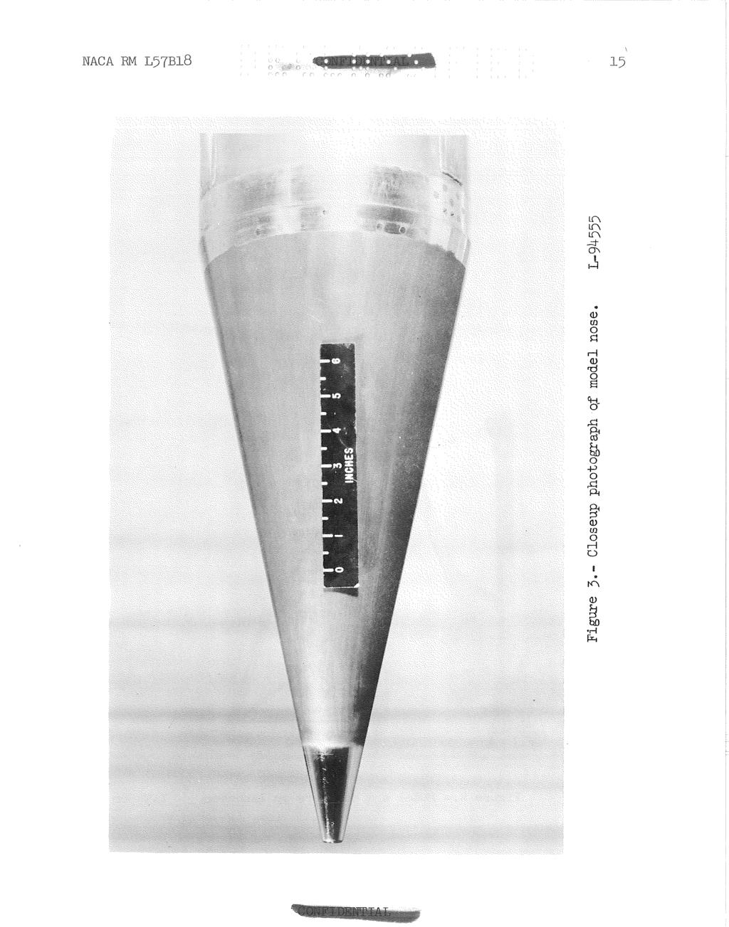
4 NACA FM ~ 57~18 X P Length from zero station density of air Subscripts: o w undisturbed free stream ahead of model wall N nose (X = 1.73) c cylinder (X = 58.73) 1 flare (X = 61.07) 2 flare (X = 66.95) 3 flare (X = 73.11) MODEL AND INSTRUMENTATION Model Configuration The model was a body of revolution 6.68 feet long with a blunted 25' cone nose section, a cylindrical midsection, and a lo0 half-angle flare tail section. Figure 1 is a sketch showing pertinent details and dimensions of the model and figures 2, 3, and 4 show photographs of the model. The conical nose was spun from Inconel sheet approximately inch thick. The blunt tip was machined from Inconel and was welded to the nose skin. Details of the nose tip are shown in the sketch of figure 1. The nose was blunted in order to eliminate melting of the sharp tip during the high-heating period of the flight. A nearly flatfaced blunting was chosen in lieu of a hemispherical tip since the larger radius of this flat type of blunting provides lower heat transfer to the nose tip. The three external channels along the cylindrical portion of the body provided cable conduits fram the telemeter in the nose to the power plugs and antenna at the base of the flare. The channels were equally spaced around the cylinder and welded to it. The cylinder and the lo0 half-angle flare section were both rolled from inch-thick Inconel and welded together. The flare skin was backed by balsa wood to aid in maintaining the conical shapes. Prior to assembly, the nose, cylinder, and flare sections were polished and then heat-treated in order to establish an oxidized skin surface whose emissivity would not change radically as the skin heated
5 during the flight. The oxide coa'ting +Tas removed from the forward inches of the blunted nose, and this porbion of the nose was high-q polished as can be seen in the photograph (fig, 31, The oxide coating was also removed near the juncture of the nose cone and cylinder at assembly of these sections. Pertinent physical properties of the Inconel skin are given in figure 5 which shows curves from reference 7 of conductivity, specific heat, and the emissivity for an oxidized surface as functions of temperature. Surface roughness of the model skin was measured with a Physicists Research Company Profilometer. The measured roughnesses, in microinches (rms), were as follows: prior to oxidizing, 3.5 to 7 on the nose cone, 10 to 20 on the cylinder, and 2 to 3 on the flare; after oxidizing, 10 to 12 on the oxidized nose surface and 2 to 3 on the highly polished forward portion of the nose. Roughness measurements were not made on the cylinder and flare after oxidizing. Instrumentation Twenty-four temperatures, five pressures, the thrust acceleration, and the drag deceleration were telemetered from the model during flight. The telemeter was carried in the nose section and was protected from the high nose-skin temperatures reached during the test by a radiation shield. The shield consisted of a cone rolled from inch-thick Inconel, spaced approximately 114 inch inside the external nose skin and supported by the solid nose tip at the forward end and by a bulkhead at the rear of the nose section. One pressure orifice was located near the forward end of the nose section, another on the cylinder just forward of the cylinder-flare junction, and three were located along the flare section, at the stations indicated in figure 1. All the orifices were on a longitudinal line along the skin which lay midway between two of the external channels. Twenty-three thermocouples were installed on the skin of the model at the locations indicated in figure 1, and one was located on the radiation shield. The eleven thermocouples on the nose skin were located along two longitudinal lines 180' apart circumferentially, six along the upper line and five at nearly duplicate stations along the lower line. The upper line was located so that, with respect to the cylinder, it lay midway between two of the external channels (120 from the line of the pressure orifices). Along this upper line, five thermocouples were also located on the cylinder and seven on the flare. All thermocouples were no. 30 chromel-alumel wire, with each wire of a thermocouple individually spot-welded to the inner surface of the skin approximately 3/16 inch apart circumferentially. During the flight several thermocouples failed to
6 operate or gave quite erratic data, These therinioeouples are so noted in the LabLe of figure 1. The measured thicknesses of the kconel skin at the locations where the thermocouples di& operate satisfactorily are given in taabl-e 7- A check of telemetered skin temperature was made just prior to launching by determining the temperatures at one of the measurement stations by means of a thermocouple taped to the exterior surface of the skin. During flight, three standard voltages and the outputs of t~aebe thermocouples were commutated on each of two telemeter channels so that each temperature measurement was recorded about five times per second. The three standard voltages were chosen equivalent to the lowest temperature, the midrange temperature, and the highest temperature that the skin thermocouples were expected to reach. Commutation of those known voltages along with the voltage readings of the thermocouples provided an in-flight check calibration of the thermocouple telemetering and recording system. Other instrumentation consisted of ground-based radar units for measuring model velocity and for obtaining the position of the model in space. Velocity data were obtained by means of CW Doppler radar through burnout of the second-stage motor (t = 29.5 seconds), and beyond this time model velocity was obtained by integration of telemetered longitudinal acceleration and also by differentis;tion of the radar flight-path data (up to firing of the fourth-stage motor). A modified SGR-584 radar tracked the model until just after firing of the fourth-s-tage motor and provided slant range, azimuth, and elevation angle fram which altitude, horizontal range, and model f light-path angle may be calculated at a given time. A modified AN/I)PN-~~ radar beacon installed in the forward end of the third-stage motor was used to extend the range of the SCR-584 radar beyond its normal skin tracking range. After firing of the fourth-stage motor, the flight-path data were extended by double integration of the telemetered longitudinal-acceleration data. Atmospheric data and wind conditions were measured to an altitude of 92,800 feet by means of a radiosonde launched near the time of flight and tracked by Rawin set A N / ~ - ~ A. Since the measured atmospheric data agreed very well with standwd atmospheric conditions at the higher altitudes, standard conditions were used to extend the data through the peak altitude of the flight. PROPULSION AND TEST TECHNIQUE The model and boosters are shown on the launcher in figure 4. The propulsion system consisted of four stages of solid-propellant rocket motors. The first and second stages were an ~6 Jato rocket motor and M5 Jato rocket motor, respectively. The third stage was a bundle of
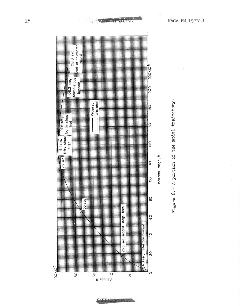
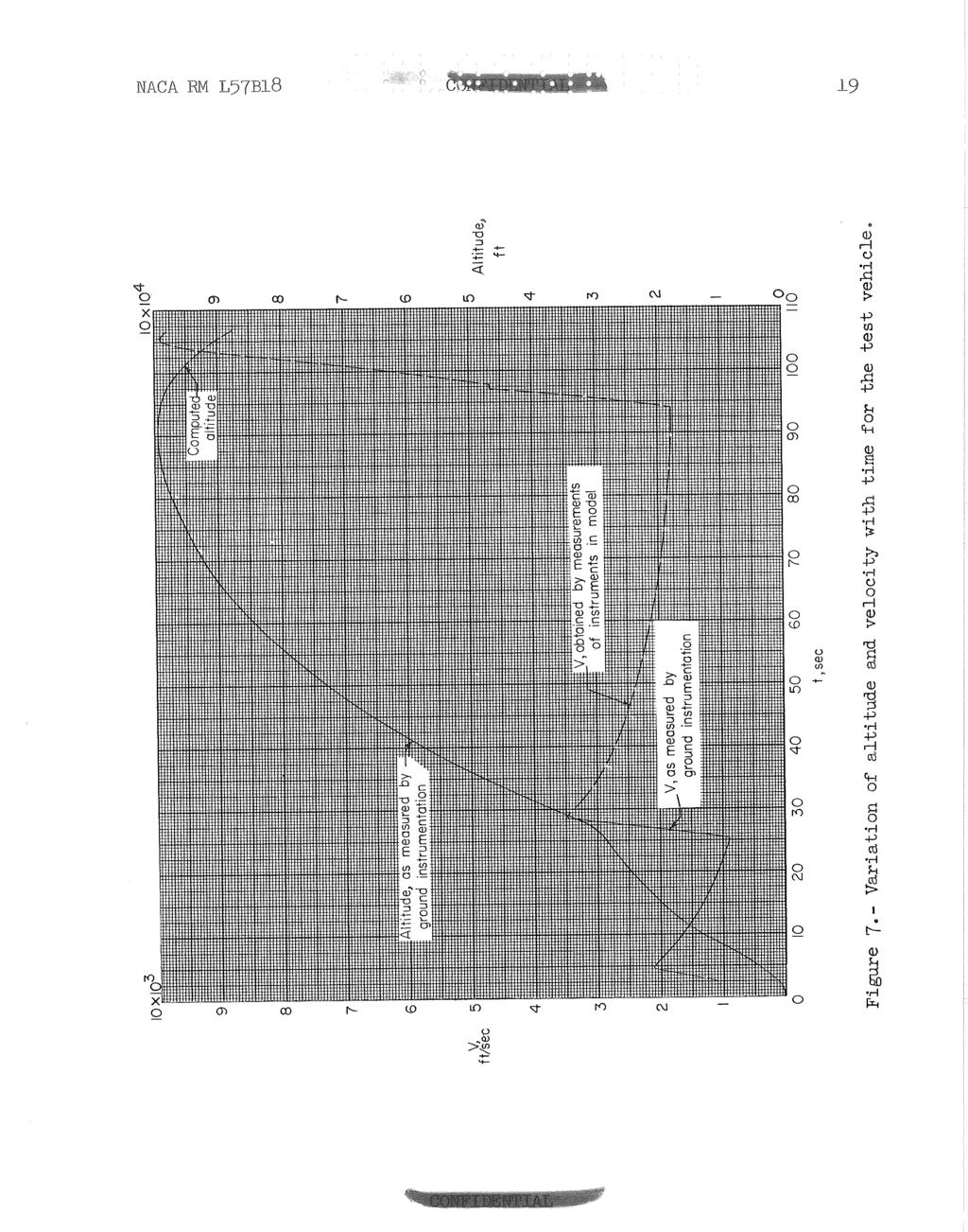
7 three AUL Deacon rocket motors, which burned sfmultaneously, and the fourth stage was a T-40 Thiokol rocket motor. The three Deacon motors comprising the third stage were enclosed within a cylindrical. skin rolled from l/8-inch magnesiuril sheet, and the T-40 miokol fowth-stage motor was carried within the cylindrical section of the model. Locking devices between the second and third stages and between the third stage and model prevented premature separation of these stages. The times at which the various stages were programed to fire were chosen so as to obtain the maximum Mach number without exceeding allowable skin temperatures and range restrictions. The model was launched at an elevation angle of 70' and the first two stages were used to boost the model and third-stage rocket motor to high altitude. A peak altitude of 99,400 feet was attained during coasting of the latter two stages, and the third stage was fired during the reentry of the model into the denser atmosphere at a flight-path angle of about -4O to the horizontal. About 0.7 second after burnout of the third-stage motor, the fourth stage fired and blasted the model free from the third stage. The fourth-stage motor accelerated the model to the maximum Mach number of 9.89 at an altitude of 89,600 feet. A portion of the reentry type of trajectory that the model followed as well as notations of the various stage firing times are shown in figure 6. The telemeter signal which had become progressively weaker from a time several seconds prior to third-stage firing ended completely 1.5 seconds after maximum Mach number was reached. However, almost complete time histories of the data were obtained up to this time. FLIGHT TEST The variation of velocity and altitude for the model through peak velocity is presented in figure 7. The mode of determination of each of these quantities, as discussed in the section entitled "~nstrumentation," is also indicated. Time histories of the free-stream velocity of sound, static pressure, temperature, and density as determined from the radiosonde measurements for the model flight are presented in figure 8. The variation of flight Mach number and Reynolds number per foot with time were obtained from the data of figures 7 and 8 and are presented in figures 9 and 10, respectively. Skin Temperatures Representative curves of the skin temperatures measured on the nose cone, cylinder, and flare during the flight are shown in figure 11to indicate general trends and magnitudes that occurred. The periods of skin cooling after about 10 seconds and 40 seconds correspond to the long
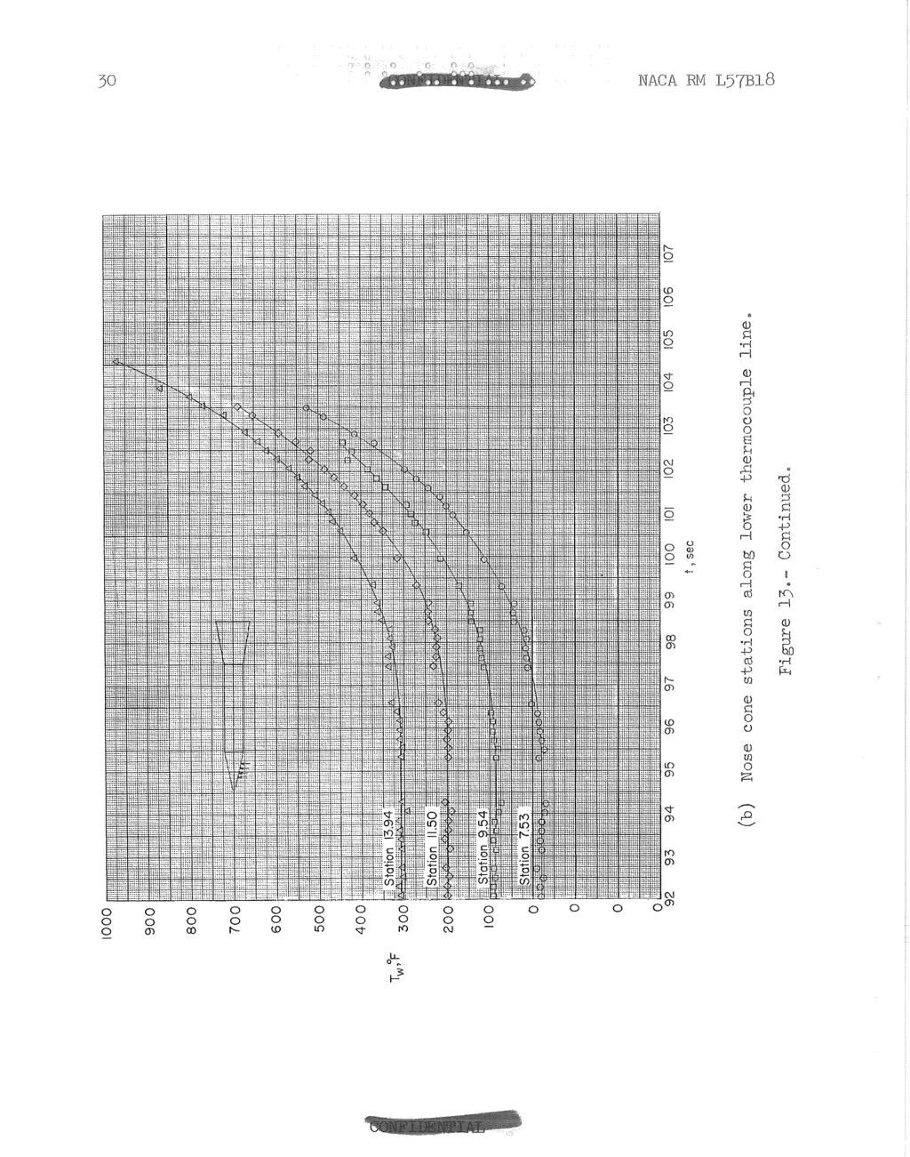
8 intervals of coasting flight after f irst-stage burnout and. second-stage burmoat, respec Lively. The measured temperature data for each stukion during the periods of strong aerodynamic heating between 24 and 42 seconds and bet+~een 9.;" seconds and the end of Lhe test are sham in figures 12 and 13, respectively. (1n order to facilita,te presentation of the da-ta, staggered scales have been used in many of the figures. ) The temperatures measured during the first interval on the upper- and lower-nose-cone stations are shown in figures 12(a) and 12(b), respectively. The uppernose-cone measurements indicate moderate rates of heating at the three forward stations, whereas the temperature rose much more rapidly at the most rearward station (station 14-18). The boundary layer was apparently laminar as far back as station 9.67 and transitional or turbulent at station Examination of the measurements along the lower thermocouples (fig. 12(b)) shows temperatures and heating rates quite similar to those measured at the most rearward upper station, thus indicating a more forward transition on the lower side of the cone. A likely cause of the asymmetrical boundary layer on the nose cone may have been the nearer proximity of the nose-cone pressure orifice to the lower thermocouple line. The temperatures measured along the cylinder from 24 to 42 seconds are shown in figure 12(c). The heating of the cylinder was moderate in comparison with the cone heathg, and the data in general shuw progressively higher heating in moving toward the rear of the cylinder. Figures 12(d) and 12(e) show the measured flare temperatures for the time interval between 24 and 42 seconds. The temperatures and heating rates were very similar at all the flare stations. The temperatures on the flare eventually reached higher values during this interval than did the hottest of the nose-cone stations, but the peak rate of heating on the flare was less than that on the nose cone. Time histories of the measured temperatures for the time interval between 92 seconds and the end of the test are shown in figure 13. As previously noted, the telemeter signal had begun to get progressively weaker several seconds prior to third-stage firing. For this reason, there is somewhat more scatter in the temperature data than at the earlier times, and for several short intervals no temperature values could be obtained. The upper- and lower-nose-cone temperatures are plotted in figures 13(a) and 13(b), respectively. 'These data clearly show a much lower rate of heat transfer along the upper thermocouple line than along the lower line and indicate that the boundary layer was probably laminar at all measurement stations on the upper line and transitional or turbulent along the lower line. Figures l3(c) and 13 (a) show the temperatures measured along the cylinder and flare, respectively. At the cylinder stations, the temperatures were' similar and the heating rates were low. On the flare, the heating rates generally increased slightly with distance from the cylinder-flare juncture. Reduction of the data to local Stanton number will be necessary to determine whether the flare heating was of the laminar or turbulent level.
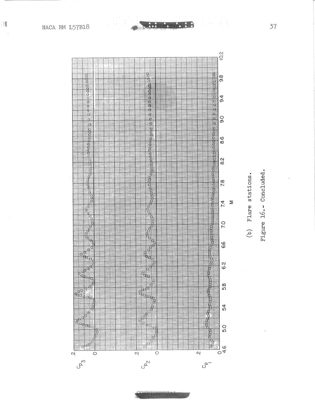
9 NACA RM ~57s1_8 In spite of the fact that the thermocouples along ihe Lower line of the nose cone did not function as Long as some of the other thelmocouples, the niaxiinum measured temperature on the model was obtained at station on the lower thermocouple Line at a time of seconds. Thl; s maximum temperature was 970' F, whereas, along the opposite side of the model, the maximum temperatures of the cone, cylinder, and flare were 545O F, 340' F, and 680' F, respectively, at the corresponding time. In figure 14, temperature distributions for the times when the flight Mach number was 6.0, 9.2, and 9.89 are presented from the data of fig- ure 13 in order to show the relative heating over the model length. The temperatures along the cylinder were generally the lowest in all cases and the flare temperatures were of higher magnitude than any- of the measurements made along the upper thermocouple line. The higher heating experienced along the lower nose thermocouple line (indicated by the shaded test is very clearly illustrated by this plot. Measure- ments at the lower cone stations were obtained at three stations only at a time of seconds (M = 9.2) and indicate a maximum temperature of 955' F at the most rearward station as compared with the maximum uppernose-cone temperature of F and maximum flare temperature of 585O F at that time. Pressure Coefficients The measured pressures on the nose, cylinder, and flare were reduced to pressure coefficients and the data are presented as a function of Mach number in figures 13 and 16. In figure 15 the data for the lower speed range (up to M = 4.67) were obtained during five separate speed intervals resulting from the alternate firing and coasting of the various booster stages. These intervals are indicated by different test points in the figure. The data for all these various intervals, in general, show rea~ona~bly good agreement. The data representing the interval of coasting of the last two stages and then the subsequent firing of the third stage show more disagreement with the trends established by the prior intervals. These data are of less accuracy than those of the prior intervals since, owing to the high altitudes, the measured pressure values are in the lower part of the full-scale range of the pressure instrumentation. nature of data obtained mostly at the early part of the firing of the third stage is believed to have been caused by angle-of-attack effects, due possibly to some slight asymmetric thrust resulting from the triple rocket arrangement of the third stage. The erratic The pressure-coefficient data for the higher speed portion of the flight were obtained during the firing of the sustainer motor in the model and are shown in figure 16. These data definitely show that the model was disturbed from its flight path as it blasted away from the third sta,ge booster, and this disturbance caused the model to oscillate
10 during part of its powered flight. A mean line fairing of the pressure oscillations will produce a smooth curve which should represent nearzero-lift pressure coefficients for the various measurement locations, In figures l5(a) and 16(a) the measured nose pressure coefficients are compared with the theoretical sharp cone pressure coefficients of reference 8. In general, the measured data are somewhat lower than the theory in the lower speed range and of slightly higher magnitude in the higher speed range. This behavior of the measured nose pressure coefficients indicates that the pressure orifice was in the region of expansion following the rapid compression caused by the blunted nose. The pressure-distribution data of reference 9, which are for a spherically tipped cone, show that the overexpansion to values below the conical values diminishes as the Mach number is increased to 3.1. The present data indicate the same trend, and, in the speed range from M = 2.8 to 3.4, the measured data agree quite well with cone theory. The configuration of reference 10 is more similar to the nose configuration employed on the test vehicle; however, pressure data reported in this reference are only for a Mach number of The pressure-distribution data of reference 10 show that higher than theoretical cone pressures were obtained on a blunted 20 cone at distances up to 2 bluntness diameters back from the nose tip. In view of these data and since the nosepressure orifice was located at less than 1 bluntness diameter from the nose tip, it is evident that the nose-cone pressure orifice was in the high-pressure expansion region during the higher speed portion of flight. In figure 17 the nose-pressure data for the portion of flight beginning with the ignition of the third stage through the burnout of the motor in the model are replotted as a function of time. The Mach number range covered during this time is also replotted in this figure. The portion from 94 seconds to 97.8 represents flight with the third stage and the erratic nature of the nose pressure coefficient in this stage suggests the possibility of asymmetric thrust which was mentioned previously. Firing of the motor in the model at 97.8 seconds produced a disturbance that resulted in a uniform oscillation which damped in about 3 seconds, thus indicating that the dynamic stability of the model was adequate in its flight at the average altitude of 96,000 feet. CONCLUDING RESIARKS A.slightly blunted cone -cylinder-f lare configuration has been flight tested by means of the rocket-model technique to a maximum Mach number of The cone had a total angle of 25O and the flare had a 10' halfangle. A reentry type of trajectory was employed in which the high-speed portion of flight was obtained during the descent of the model from a peak altitude of 99,400 feet. A relatively large quantity of telemetered
11 Lnf ormati-on was obtained on the conf igura,tion, i-ncluding nineteen skin temperatures and ftve pressures, until 1.5 seconds after maximum Mach number. During the higher speed portion of flight, temperature measurements along one element of the nose cone indicated that the boundary layer was probably laminar, whereas on the opposite side of the nose the measurements indicated transitional or turbulent flow. Temperature distributions along one meridian of the model showed the flare to have the highest temperatures and the cylinder generally to have the lowest. On the flare, the heating rates generally increased with distance from the flarecyjinder juncture. Langley Aeronautic a1 Laboratory, National Advisory Committee for Aeronautics, Langley Field, Va., January 31, 1937.
12 NACA F&l ~ 5 7 ~ ~ 8 1, Rumsey, Cba,rles B., Piland, Robert Oa, and Nopko, Russell N': Aerodynamic-Heating Data Obtained From Free-Flight Tests Between Mach Numbers of 1 and 5. NACA RM ~55~14a, Rumsey, Charles B.: Free-Flight Measurements of Aerodynamic Heat Transfer to Ivlzch Number 3.9 and of Drag to Mach Number 6.9 of a Fin-Stabilized Cone-Cylinder Configuration. NACA RM ~55~28a, 1955.?..Piland, Robert O., Collie, Katherine A., and Stoney, William E.: Turbulent and Laminar Heat-Transfer Measurements on a 1/6-~cale NACA RM-10 Missile in Free Flight to a Mach Number of 4.2 and to a Wall Temperature of 1400~ R. NACA RM ~56~05, Rumsey, Charles B., and Lee, Dorothy B.: Measurements of Aerodynamic Heat Transfer and Boundary-Layer Transition on a 10' Cone in Free Flight at Supersonic I@ich Numbers up to 5.9. NACA RM ~561307, Rumsey, Charles B., and Lee, Dorothy 33.: Measurements of Aerodynamic Heat Transfer and Boundary-Layer Transitiorf on a 15' Cone in Free Flight at Supersonic bbch Numbers up to 5.2. NACA RM ~56~26, Piland, Robert 0.: Performance Measurements From a Rocket-Powered Exploratory Research Missile Flown to a I@ich Number of NACA RM L54~29a, OISullivanJ William J., Jr.: Some Thermal and Mechanical Properties of Inconel at High Temperatures for Use in Aerodynamic Heating Research. Proc. A.S.T.M., vol. 55, 1955, pp Arnes Research Staff: Equations, IPdbles, and Charts for Compressible Flow. NACA Rep. 1135, (supersedes NaCA TN ) 9. Perkins, Edward W., and Jorgensen, Leland H.: Investigation of the Drag of Various Axially Symmetric Nose Shapes of Fineness Ratio 3 for hch Numbers From 1.24 to NACA RM ~52~28, Bertram, Mitchel H. : Tip-Bluntness Effects on Cone Pressures at M = Jow. Aero. Sci. (~eaders Forum), vol. 23, no. 9, Sept. 1956, pp
13 TABLE I SKIN THICKNESS AT TRERIVIOCOUPLE: STATIONS Nose Cylinder Flare
14 I I I.. *did not operate Figure 1.- Sketch of model and detail of nose construction. All dimensions are in inehes, dh. pressure J equally spaced l ~ i n of e orifices Nose detail X for pressure orifices On On On nose cylinder flare
15
16
17 NACA RM L Figure 4. - Model and boosters on launcher. L-94566
18
19
20

21 NACA RM 1, X i-' er-4 0 rl a, >
22 NACA RM ~57~18

23 Figure 10.- Variation of Reynolds nurrber per foot with time for the test vehicle.
24
25 NACA RM ~57818
26 - t, sec (b) Nose cone stations along lower thermocouple line. Figure 12.- Continued.
27 0.I d - * 0 d- o) IC) 00 M P- IC) (C, IC) id M d IC) 0 a, U) IC) - IC)+ CU IC) - Ic) 0 Ic) 0, CU 0 N i- CU w N LD N d- (U
28
29

30 NACA RM ~57~18 :
31
32
33
34 X, in. Figure 14.- Temperature distribution during high-speed portion of flight.

35 t" (a) Nose and cylinder stations. s I--' Figure 15.- Pressure coefficients as a function of Mach number for the lower speed portion of flight.
36
37 NACA RM ~57~318
38

39 t, sec F Figure 17.- Variation of nose pressure coefficient and Mach number with time during the high- 3 : speed portion of flight. P CZ?

40
RESEARCH MEMORANDUM AND SURFACE-PRESSURE MEASUREMENTS ON A HIGHLY POLISHED NOSE HAVING A 100 TOTAL-ANGLE CONE AND A
 RESEARCH MEMORANDUM FREE-FIJGHT SKIN-TEMPERATURE AND SURFACE-PRESSURE MEASUREMENTS ON A HIGHLY POLISHED NOSE HAVING A 100 TOTAL-ANGLE CONE AND A IO0 HALF-ANGLE CONICAL FLAR,E SECTION UP TO A MACH NUMBER
MACH NUMBERS BETWEEN 0.8 AND 2.2 AS DETERMINED FROM THE
 NACA RM SL5kH2 NATIONAL ADVISORY COMMI'ITEE FOR AERONAUTICS RESEARCH MEMORANDUM for the Bureau of Aeronautics, Department of the Navy mo-lift DRAG OF THE CHANCE VOUGHT Rl3GULUS I1 MISSILE AT MACH NUMBERS
RESEARCH MEMORANDUM FUGHT CHARACTERSSTICS OF A WINGIZSS ROCKET-POWERED MODEL WITH FOUR EXTERNALLY MOUNTED AIR-TO-APR MISSILES,$ Langley.Field, Va.
 3 1176 6 693 i RESEARCH MEMORANDUM FUGHT CHARACTERSSTCS OF A WNGZSS ROCKET-POWERED MODEL 'r- WTH FOUR EXTERNALLY MOUNTED AR-TO-APR MSSLES,$ AT MACH NUMBERS FROM.7 TO 1.6 By Allen B. Henning and Clarence
Initial Trajectory and Atmospheric Effects
 Initial Trajectory and Atmospheric Effects G. Flanagan Alna Space Program July 13, 2011 Introduction A major consideration for an earth-based accelerator is atmospheric drag. Drag loses mean that the gun
TECHNICAL NOTE D ABLATING UNDER CONSTANT AERODYNAMIC CONDITIONS. By Robert R. Howell. Langley Research Center Langley Station, Hampton, Va.
 -. NASA TN D-1635 TECHNICAL NOTE 1 D- 1635 AN EXPERIMENTAL STUDY OF THE BEHAVIOR OF SPHERES ABLATING UNDER CONSTANT AERODYNAMIC CONDITIONS By Robert R. Howell Langley Research Center Langley Station, Hampton,
Nose Cone & Fin Optimization
 Nose Cone & Fin Optimization Tripoli Minnesota Gary Stroick January 2011 Purpose Focus is on drag optimization to maximize rocket performance! Copyright 2011 by Off We Go Rocketry 2 Agenda Definitions
NATIONAL ADVISORY COMMITTEE ix FOR AERONAUTICS. I 1 I/ $. t. Langley Aeronautical Laboratory. Washington TECHNICAL NOTE 3861
 * NATIONAL ADVISORY COMMITTEE ix c t. e... 9 FOR AERONAUTICS. TECHNICAL NOTE 3861 \ d \ I 1 I/ $. t I 4' \,,,',I i. * I*---,h,q ~,-,. I AERODYNAMIC CHARACTERISTICS OF A CIRCULAR CYLINDER AT MACH NUMBER
NACA AERODYNAMIC HEATING OF A WING AS DETERMINED. By Andrew G. Swanson and Charles B. Rumsey. Langley Aeronautical Laboratory Langley Field, Va.
 RM L56Flla NACA a RESEARCH MEMORANDUM AERODYNAMIC HEATING OF A WING AS DETERMINED FROM A FREE -FLIGHT ROCKET-MODEL TEST TO MACH NUMBER 3.64 By Andrew G. Swanson and Charles B. Rumsey Langley Aeronautical
NATIONALADVISORY COMMITTEE FOR AERONAUTICS TECHNICAL NOTE 4214 AT MACH 3.1. Paul F. Brinich. Flight Propulsion Laboratory Cleveland, Ohio.
 r NATONALADVSORY COMMTTEE FOR AERONAUTCS TECHNCAL NOTE 4214 BOUNDARY -LAYER TRANSTON ON AN OPEN -NOSE CONE AT MACH 3.1 By Paul F. Brinich Lewis Flight Propulsion Laboratory Cleveland, Ohio =w= Washington
Ramjets: Thermal Management An Integrated Engineering Approach
 Ramjets: Thermal Management An Integrated Engineering Approach Ronald G. Veraar TNO Defence, Security and Safety P.O. Box 45 2280 AA Rijswijk NETHERLANDS ronald.veraar@tno.nl ABSTRACT Within the framework
Principles of Rocketry
 1-1 Principles of Rocketry 1-2 Water Rockets BASIC CONCEPTS 1-3 What is a Rocket? A chamber enclosing a gas under pressure. A balloon is a simple example of a rocket. Rubber walls compress the air inside.
EXTERNAL-JET (FLUID) PROPULSION ANALOGY FOR PHOTONIC (LASER) PROPULSION By John R. Cipolla, Copyright February 21, 2017
 PROPULSION ANALOGY FOR PHOTONIC (LASER) PROPULSION By John R. Cipolla, Copyright February 21, 2017") EXTERNAL-JET (FLUID) PROPULSION ANALOGY FOR PHOTONIC (LASER) PROPULSION By John R. Cipolla, Copyright February 21, 2017 ABSTRACT External-jet propulsion uses a narrow jet of high velocity water or conceptually
EXTERNAL-JET (FLUID) PROPULSION ANALOGY FOR PHOTONIC (LASER) PROPULSION By John R. Cipolla, Copyright February 21, 2017 ABSTRACT External-jet propulsion uses a narrow jet of high velocity water or conceptually
Technology of Rocket
 Technology of Rocket Parts of Rocket There are four major parts of rocket Structural system Propulsion system Guidance system Payload system Structural system The structural system of a rocket includes
SPC Aerodynamics Course Assignment Due Date Monday 28 May 2018 at 11:30
 SPC 307 - Aerodynamics Course Assignment Due Date Monday 28 May 2018 at 11:30 1. The maximum velocity at which an aircraft can cruise occurs when the thrust available with the engines operating with the
What is the crack propagation rate for 7075-T6 aluminium alloy.
 - 130 - APPENDIX 4A 100 QUESTIONS BASED ON SOURCE DOCUMENTS LISTED IN APPENDIX 4B 20-06 Magnitude of reductions in heat transfer on the nose region of a body when ablation of the surface takes place. (PI2002)
RESEARCH MEMORANDUM NATIONAL ADVISORY COMMITTEE FOR AERONAUTICS. -9:.f CANCELLED. . *..,t--:;.,q. By Edward C. Polhamus and Thomas J. Ring, Jr.
 RESEARCH MEMORANDUM AERODYNAMIC CIylRACTEmTICS WITH FEED AND FRcEE TRAN;SITION '",? f- I r\ t 7-1. *..,t--:;.,q OF A MODIFIED DELTA WINGIN COMBINATION WITH A FUSEIAGE AT EIGE SUBSONIC SPEEDS By Edward
AN ENGINEERING LEVEL PREDICTION METHOD FOR NORMAL-FORCE INCREASE DUE TO WEDGE SECTIONS
 27 TH INTERNATIONAL CONGRESS OF THE AERONAUTICAL SCIENCES AN ENGINEERING LEVEL PREDICTION ETHOD FOR NORAL-FORCE INCREASE DUE TO WEDGE SECTIONS Asher Sigal Shehafim R&D, Haifa 34861, Israel Keywords: wedge
Lecture1: Characteristics of Hypersonic Atmosphere
 Module 1: Hypersonic Atmosphere Lecture1: Characteristics of Hypersonic Atmosphere 1.1 Introduction Hypersonic flight has special traits, some of which are seen in every hypersonic flight. Presence of
Department of Mechanical Engineering
 Department of Mechanical Engineering AMEE401 / AUTO400 Aerodynamics Instructor: Marios M. Fyrillas Email: eng.fm@fit.ac.cy HOMEWORK ASSIGNMENT #2 QUESTION 1 Clearly there are two mechanisms responsible
RESEARCH MEMORANDUM. JUL3 1%-i NATIONAL ADVISORY COMMITTEE. 8 Langley Aeronautical Laboratory Langley Ffeld$XASSIFICATION CHANGED
 03 0 w r-l t- z JUL3 1%-i RESEARCH MEMORANDUM LFT AND DRAG COEFFCENTS FOR THE BELL X-1 ARPLANE (8-PEFCEN"TEUCK WNG) N POWER-OFF 3 TFUWSONC FLGHT By L. Robert Carman and John R. Carden B 8 Langley Aeronautical
Brenda M. Kulfan, John E. Bussoletti, and Craig L. Hilmes Boeing Commercial Airplane Group, Seattle, Washington, 98124
 AIAA--2007-0684 Pressures and Drag Characteristics of Bodies of Revolution at Near Sonic Speeds Including the Effects of Viscosity and Wind Tunnel Walls Brenda M. Kulfan, John E. Bussoletti, and Craig
THE METEOROLOGICAL ROCKET SYSTEM FOR ATMOSPHERIC RESEARCH
 THE METEOROLOGICAL ROCKET SYSTEM FOR ATMOSPHERIC RESEARCH Komissarenko Alexander I. (1) Kuznetsov Vladimir M. (1) Filippov Valerii V. (1) Ryndina Elena C. (1) (1) State Unitary Enterprise KBP Instrument
AERODYNAMIC COEFFICIENTS FOR EXTENDING AND BENDING PROJECTILES. William G. Reinecke*
 23 RD INTERNATIONAL SYMPOSIUM ON BALLISTICS TARRAGONA, SPAIN 16-20 APRIL 2007 AERODYNAMIC COEFFICIENTS FOR EXTENDING AND BENDING PROJECTILES William G. Reinecke* Institute for Advanced Technology.The University
Asymmetry Features Independent of Roll Angle for Slender Circular Cone
 47th AIAA Aerospace Sciences Meeting Including The New Horizons Forum and Aerospace Exposition 5-8 January 2009, Orlando, Florida AIAA 2009-905 47th AIAA Aerospace Sciences Meeting Including The New Horizons
AE Stability and Control of Aerospace Vehicles
 AE 430 - Stability and ontrol of Aerospace Vehicles Static/Dynamic Stability Longitudinal Static Stability Static Stability We begin ith the concept of Equilibrium (Trim). Equilibrium is a state of an
RESEARCH MEMORANDUM AERODYNAMIC HEATING AND BOUNDARY-MYER TRANSITION ON A. l/io-power NOSE SHAPE IN FREE FLIGHT AT MACH NUMBERS
 262 COPY RM L57E14a RESEARCH MEMORANDUM AERODYNAMIC HEATING AND BOUNDARY-MYER TRANSITION ON A l/io-power NOSE SHAPE IN FREE FLIGHT AT MACH NUMBERS.: -. f Tjp 0 6.7.&D. FREE-STREAM REYNOLDS N-UlMBERS :
NUMERICAL OPTIMIZATION OF THE SHAPE OF A HOLLOW PROJECTILE
 NUMERICAL OPTIMIZATION OF THE SHAPE OF A HOLLOW PROJECTILE Wessam Mahfouz Elnaggar, Zhihua Chen and Hui Zhang Key Laboratory of Transient Physics, Nanjing University of Science and Technology, Nanjing,
Part 3. Stability and Transition
 Part 3 Stability and Transition 281 Overview T. Cebeci 1 Recent interest in the reduction of drag of underwater vehicles and aircraft components has rekindled research in the area of stability and transition.
Separable warhead mathematical model of Supersonic & Hypersonic Re-entry Vehicles
 16 th International Conference on AEROSPACE SCIENCES & AVIATION TECHNOLOGY, ASAT - 16 May 26-28, 2015, E-Mail: asat@mtc.edu.eg Military Technical College, Kobry Elkobbah, Cairo, Egypt Tel : +(202) 24025292
IAC-11-A2.5.9 RE-ENTRY ANALYSIS OF RESEARCH ROCKET PAYLOADS
 RE-ENTRY ANALYSIS OF RESEARCH ROCKET PAYLOADS Andreas Stamminger Deutsches Zentrum für Luft- und Raumfahrt (DLR), Mobile Rocket Base, Oberpfaffenhofen, 82234 Wessling, Germany, Tel.: 49-8153-28-1231, Email:
MODELLING AND CFD ANALYSIS OVER A MISSILE BLUNT BODY WITH SPHERICAL AEROSPIKE
 MODELLING AND CFD ANALYSIS OVER A MISSILE BLUNT BODY WITH SPHERICAL AEROSPIKE N. Tulasi Radha 1, K. Dorathi 2 12 Faculty members of Mechanical Engineering, Sri Vasavi Engineering College, Tadepalligudem-534
Drag coefficient modelling in the context of small launcher optimisation
 Drag coefficient modelling in the context of small launcher optimisation Alexandru-Iulian ONEL*,1, Tudorel-Petronel AFILIPOAE 1, Ana-Maria NECULAESCU 1, Mihai-Victor PRICOP 1 *Corresponding author 1 INCAS
ADVANCES in NATURAL and APPLIED SCIENCES
 ADVANCES in NATURAL and APPLIED SCIENCES ISSN: 1995-0772 Published BY AENSI Publication EISSN: 1998-1090 http://www.aensiweb.com/anas 2016 Special 10(6): pages 79-88 Open Access Journal Effect of Variable
AC : A DESIGN-BY-ANALYSIS PROJECT FOR INTRODUC- TORY STUDENTS IN AEROSPACE ENGINEERING
 AC 2012-4116: A DESIGN-BY-ANALYSIS PROJECT FOR INTRODUC- TORY STUDENTS IN AEROSPACE ENGINEERING Dr. Mark Anderson, University of California, San Diego c American Society for Engineering Education, 2012
Contents. Preface... xvii
 Contents Preface... xvii CHAPTER 1 Idealized Flow Machines...1 1.1 Conservation Equations... 1 1.1.1 Conservation of mass... 2 1.1.2 Conservation of momentum... 3 1.1.3 Conservation of energy... 3 1.2
EFFECT OF BODY SHAPE ON THE AERODYNAMICS OF PROJECTILES AT SUPERSONIC SPEEDS
 Journal of Engineering Science and Technology Vol. 3, o. 3 (8) 78-9 School of Engineering, Taylor s University College EFFECT OF BODY SHAPE O THE AERODYAICS OF PROJECTILES AT SUPERSOIC SPEEDS ABDULKAREE
Introduction to Aerospace Engineering
 4. Basic Fluid (Aero) Dynamics Introduction to Aerospace Engineering Here, we will try and look at a few basic ideas from the complicated field of fluid dynamics. The general area includes studies of incompressible,
Drag Analysis of a Supermarine. Spitfire Mk V at Cruise Conditions
 Introduction to Flight Aircraft Drag Project April 2016 2016 Drag Analysis of a Supermarine Spitfire Mk V at Cruise Conditions Nicholas Conde nicholasconde@gmail.com U66182304 Introduction to Flight Nicholas
AERODYNAMIC OF REENTRY SPACECRAFT CLIPPER
 EUROPEAN CONFERENCE FOR AEROSPACE SCIENCES (EUCASS) AERODYNAMIC OF REENTRY SPACECRAFT CLIPPER A.A. Dyadkin, A.N. Krylov, A.G. Reshetin, Yu.P. Semenov, T.V. Simakova, V.A. Tokarev S.P. Korolev Rocket and
Introduction to Flight
 l_ Introduction to Flight Fifth Edition John D. Anderson, Jr. Curator for Aerodynamics, National Air and Space Museum Smithsonian Institution Professor Emeritus University of Maryland Me Graw Higher Education
Fin design mission. Team Members
 Fin design mission Team Members Mission: Your team will determine the best fin design for a model rocket. You will compare highest altitude, flight characteristics, and weathercocking. You will report
Missile Interceptor EXTROVERT ADVANCED CONCEPT EXPLORATION ADL P Ryan Donnan, Herman Ryals
 EXTROVERT ADVANCED CONCEPT EXPLORATION ADL P- 2011121203 Ryan Donnan, Herman Ryals Georgia Institute of Technology School of Aerospace Engineering Missile Interceptor December 12, 2011 EXTROVERT ADVANCED
Applied Fluid Mechanics
 Applied Fluid Mechanics 1. The Nature of Fluid and the Study of Fluid Mechanics 2. Viscosity of Fluid 3. Pressure Measurement 4. Forces Due to Static Fluid 5. Buoyancy and Stability 6. Flow of Fluid and
DEVELOPMENT OF A COMPRESSED CARBON DIOXIDE PROPULSION UNIT FOR NEAR-TERM MARS SURFACE APPLICATIONS
 DEVELOPMENT OF A COMPRESSED CARBON DIOXIDE PROPULSION UNIT FOR NEAR-TERM MARS SURFACE APPLICATIONS Erin Blass Old Dominion University Advisor: Dr. Robert Ash Abstract This work has focused on the development
Evaluation of Surface Finish Affect on Aerodynamic Coefficients Of Wind Tunnel Testing Models
 Evaluation of Finish Affect on Aerodynamic Coefficients Of Wind Tunnel Testing s R. ADELNIA 1, S. AGHANAJAFI 2, S. DANESHMAND 3 Department of Mechanical Engineering Islamic Azad University Majlesi Branch
Fluctuating Pressure Inside/Outside the Flow Separation Region in High Speed Flowfield
 Journal of Aerospace Science and Technology 1 (2015) 18-26 doi: 10.17265/2332-8258/2015.01.003 D DAVID PUBLISHING Fluctuating Pressure Inside/Outside the Flow Separation Region in High Speed Flowfield
Effect Of Inlet Performance And Starting Mach Number On The Design Of A Scramjet Engine
 Effect Of Inlet Performance And Starting Mach Number On The Design Of A Scramjet Engine P. Karthikeyan 1, B. Prakash 3 2, S. R. Balakrishnan 3 PG scholar 1, Professor 2, Director/H.O.D 3 1,2,3 Department
Performance Characterization of Supersonic Retropropulsion for Application to High-Mass Mars Entry, Descent, and Landing
 Performance Characterization of Supersonic Retropropulsion for Application to High-Mass Mars Entry, Descent, and Landing Ashley M. Korzun 1 and Robert D. Braun 2 Georgia Institute of Technology, Atlanta,
Lecture-4. Flow Past Immersed Bodies
 Lecture-4 Flow Past Immersed Bodies Learning objectives After completing this lecture, you should be able to: Identify and discuss the features of external flow Explain the fundamental characteristics
Small Entry Probe Trajectories for Mars
 CubeSat (re-)entry can mean burning up in the atmosphere Here, we discuss surviving atmospheric entry We must model & understand flight dynamics, aerodynamics, heating Motivation for CubeSat entry Support
The Computations of Jet Interaction on a Generic Supersonic Missile
 The Computations of Jet Interaction on a Generic Supersonic Missile *Jinbum Huh 1) and Seungsoo Lee 2) 1), 2) Department of Aerospace Engineering, Inha Univ., Incheon, Korea 2) slee@inha.ac.kr ABSTRACT
PRINCIPLES OF FLIGHT
 1 Considering a positive cambered aerofoil, the pitching moment when Cl=0 is: A infinite B positive (nose-up). C negative (nose-down). D equal to zero. 2 The angle between the aeroplane longitudinal axis
FLIGHT DYNAMICS. Robert F. Stengel. Princeton University Press Princeton and Oxford
 FLIGHT DYNAMICS Robert F. Stengel Princeton University Press Princeton and Oxford Preface XV Chapter One Introduction 1 1.1 ELEMENTS OF THE AIRPLANE 1 Airframe Components 1 Propulsion Systems 4 1.2 REPRESENTATIVE
Aerodynamic Study of Payload Fairing
 Aerodynamic Study of Payload Fairing Pranav Mahamuni 1, Pratik Bhansali 1, Akhilesh Kulkarni 1, Yash Parikh 2 U.G. Student, Department of Mechanical Engineering, Sinhgad Institute of Technology and Science,
Experimental Aerodynamics. Experimental Aerodynamics
 Lecture 6: Slender Body Aerodynamics G. Dimitriadis Slender bodies! Wings are only one of the types of body that can be tested in a wind tunnel.! Although wings play a crucial role in aeronautical applications
CFD ANALYSIS OF AERODYNAMIC HEATING FOR HYFLEX HIGH ENTHALPY FLOW TESTS AND FLIGHT CONDITIONS
 24 TH INTERNATIONAL CONGRESS OF THE AERONAUTICAL SCIENCES CFD ANALYSIS OF AERODYNAMIC HEATING FOR HYFLEX HIGH ENTHALPY FLOW TESTS AND FLIGHT CONDITIONS Keiichi Murakami*, Yukimitsu Yamamoto*, Olivier Rouzand**
Development of Flow over Blunt-Nosed Slender Bodies at Transonic Mach Numbers
 Development of Flow over Blunt-Nosed Slender Bodies at Transonic Mach Numbers Gireesh Yanamashetti 1, G. K. Suryanarayana 2 and Rinku Mukherjee 3 1 PhD Scholar & Senior Scientist, 2 Chief Scientist, 3
AEROSPACE ENGINEERING DEPARTMENT. Second Year - Second Term ( ) Fluid Mechanics & Gas Dynamics
 Fluid Mechanics & Gas Dynamics") AEROSPACE ENGINEERING DEPARTMENT Second Year - Second Term (2008-2009) Fluid Mechanics & Gas Dynamics Similitude,Dimensional Analysis &Modeling (1) [7.2R*] Some common variables in fluid mechanics include:
AEROSPACE ENGINEERING DEPARTMENT Second Year - Second Term (2008-2009) Fluid Mechanics & Gas Dynamics Similitude,Dimensional Analysis &Modeling (1) [7.2R*] Some common variables in fluid mechanics include:
Flow Simulation over Re-Entry Bodies at Supersonic & Hypersonic Speeds
 International Journal of Engineering Research and Development eissn : 2278-067X, pissn : 2278-800X, www.ijerd.com Volume 2, Issue 4 (July 2012), PP. 29-34 Flow Simulation over Re-Entry Bodies at Supersonic
Hypersonic flow and flight
 University of Stuttgart, Aerospace Engineering and Geodesy Dept. - Lecture - Hypersonic flow and flight Master Level, Specialization 4 lecture hours per week in WS, 3-6 LPs/ECTS Lecturer: Dr. Markus J.
C LEARI N4 S E. FOR VEDBkP.,:AL., SCLNTWC",. AN [ P. TECHNICAL 1 F RiM]7MATION. KardcopyI T M icrofihe 1 I)J
![C LEARI N4 S E. FOR VEDBkP.,:AL., SCLNTWC,. AN [ P. TECHNICAL 1 F RiM]7MATION. KardcopyI T M icrofihe 1 I)J](/thumbs/96/127971289.jpg "C LEARI N4 S E. FOR VEDBkP.,:AL., SCLNTWC,. AN [ P. TECHNICAL 1 F RiM]7MATION. KardcopyI T M icrofihe 1 I)J") C LEARI N4 S E FOR VEDBkP.,:AL., SCLNTWC",. AN [ P TECHNICAL 1 F RiM]7MATION KardcopyI T M icrofihe 1 I)J.S 0 A CORRELATION OF THE BASE DRAG OF BODIES-OF-REVOLUTION WITH A JET EXHAUSTING THROUGH THE BASE
C LEARI N4 S E FOR VEDBkP.,:AL., SCLNTWC",. AN [ P TECHNICAL 1 F RiM]7MATION KardcopyI T M icrofihe 1 I)J.S 0 A CORRELATION OF THE BASE DRAG OF BODIES-OF-REVOLUTION WITH A JET EXHAUSTING THROUGH THE BASE
MDTS 5734 : Aerodynamics & Propulsion Lecture 1 : Characteristics of high speed flight. G. Leng, MDTS, NUS
 MDTS 5734 : Aerodynamics & Propulsion Lecture 1 : Characteristics of high speed flight References Jack N. Nielsen, Missile Aerodynamics, AIAA Progress in Astronautics and Aeronautics, v104, 1986 Michael
Prediction of Top of Descent Location for Idle-thrust Descents
 Prediction of Top of Descent Location for Idle-thrust Descents Laurel Stell NASA Ames Research Center Background 10,000 30,000 ft Vertical profile from cruise to meter fix. Top of Descent (TOD) idle thrust
VSB-30 sounding rocket: history of flight performance
 doi: 10.5028/jatm.2011. 03032211 Alexandre Garcia * alexandregarciaag@iae.cta.br Sidney Servulo Cunha Yamanaka sidneysscy@iae.cta.br Alexandre Nogueira Barbosa nogueiraanb@iae.cta.br Francisco Carlos Parquet
RECENT near-sonic and low-sonic boom transport aircraft
 JOURNAL OF AIRCRAFT Vol. 44, No. 6, November December 2007 Aerodynamic Characteristics of Bodies of Revolution at Near-Sonic Speeds Brenda M. Kulfan, John E. Bussoletti, and Craig L. Hilmes The Boeing
Preface. 2 Cable space accelerator 39
 Contents Abstract Preface xiii xv 1 Space elevator, transport system for space elevator, 1 and tether system 1.1 Brief history 1 1.2 Short description 2 1.3 Transport system for the space elevator 5 1.4
Ldngley Station, Hm~pton, Va, by RandoFh A. Graves, Jr., and WiZZiam G. Witte
 LOAN COPY: RETURN TO AFWL (WLIL-2) KIRTLAND AFB, N @EX FLIGHT-TEST ANALYSIS OF APOLLO HEAT-SHIELD MATERIAL USING THE PACEMAKER VEHICLE SYSTEM by RandoFh A. Graves, Jr., and WiZZiam G. Witte Langley Research
Applied Thermodynamics - II
 Gas Turbines Sudheer Siddapureddy sudheer@iitp.ac.in Department of Mechanical Engineering Jet Propulsion - Classification 1. A heated and compressed atmospheric air, mixed with products of combustion,
WSGC Collegiate Rocket Competition Design Analysis Team ChlAM. Max Strassman, Chloe Tinius, Andrew Udelhoven
 WSGC Collegiate Rocket Competition Design Analysis Team ChlAM Max Strassman, Chloe Tinius, Andrew Udelhoven University of Wisconsin Madison Department of Engineering Physics ABSTRACT The WSGC Collegiate
Drag (2) Induced Drag Friction Drag Form Drag Wave Drag
 Induced Drag Friction Drag Form Drag Wave Drag") Drag () Induced Drag Friction Drag Form Drag Wave Drag Outline Nomenclature and Concepts Farfield Drag Analysis Induced Drag Multiple Lifting Surfaces Zero Lift Drag :Friction and Form Drag Supersonic
Drag () Induced Drag Friction Drag Form Drag Wave Drag Outline Nomenclature and Concepts Farfield Drag Analysis Induced Drag Multiple Lifting Surfaces Zero Lift Drag :Friction and Form Drag Supersonic
HYPERSONIC FLOWFIELD AND HEAT FLUX PECULIARITIES ON THE NEW SPACE LAUNCHER WITH WINGED REUSABLE FIRST STAGE.
 HYPERSONIC FLOWFIELD AND HEAT FLUX PECULIARITIES ON THE NEW SPACE LAUNCHER WITH WINGED REUSABLE FIRST STAGE. S.M. Drozdov*, V.N. Brazhko*, V.E. Mosharov*, A.S. Skuratov*, D.S. Fedorov*, V.V. Gorbatenko**,
WIND INSTABILITY WHAT BARROWMAN LEFT OUT
 WIND INSTABILITY WHAT BARROWMAN LEFT OUT by Robert Galejs galejs@ll.mit.edu In Centuri TIR-33 (reprinted in the March 98 issue of High Power Rocketry), Jim Barrowman outlined a method for the determination
ME 6139: High Speed Aerodynamics
 Dr. A.B.M. Toufique Hasan Professor Department of Mechanical Engineering, BUET Lecture-01 04 November 2017 teacher.buet.ac.bd/toufiquehasan/ toufiquehasan@me.buet.ac.bd 1 Aerodynamics is the study of dynamics
* A. r 11N. Distance of Retrorocket Exhaust Plumes Intor an Oncoming Stream D! D $SD.TDR MAY 1964 CONTRACT NO.
 $SD.TDR-64-23 -Penetration Distance of Retrorocket Exhaust Plumes Intor an Oncoming Stream 11 MAY 1964 Prepared by S. E. r,,lles, J. M. KALLIS Applied Mechanics Divis ion Prepared for COMMANDER. SPACE
Given a stream function for a cylinder in a uniform flow with circulation: a) Sketch the flow pattern in terms of streamlines.
 Sketch the flow pattern in terms of streamlines.") Question Given a stream function for a cylinder in a uniform flow with circulation: R Γ r ψ = U r sinθ + ln r π R a) Sketch the flow pattern in terms of streamlines. b) Derive an expression for the angular
Question Given a stream function for a cylinder in a uniform flow with circulation: R Γ r ψ = U r sinθ + ln r π R a) Sketch the flow pattern in terms of streamlines. b) Derive an expression for the angular
DEPARTMENT OF AEROSPACE ENGINEERING, IIT MADRAS M.Tech. Curriculum
 DEPARTMENT OF AEROSPACE ENGINEERING, IIT MADRAS M.Tech. Curriculum SEMESTER I AS5010 Engg. Aerodyn. & Flt. Mech. 3 0 0 3 AS5020 Elements of Gas Dyn. & Propln. 3 0 0 3 AS5030 Aircraft and Aerospace Structures
REDUCTION OF AERODYNAMIC HEATING AND DRAG WITH OPPOSING JET THROUGH EXTENDED NOZZLE IN HIGH ENTHALPY FLOW
 REDUCTION OF AERODYNAMIC HEATING AND DRAG WITH OPPOSING JET THROUGH EXTENDED NOZZLE IN HIGH ENTHALPY FLOW Naoki Morimoto, Shigeru Aso, Yasuhiro Tani Kyushu University, Fukuoka, Japan Keywords: Thermal
LOCATING THE WASHINGTON MONUMENT GEODETIC BASE IN THE ISLAND OF GRAND CANARY MEASURED BY THE HYDROGRAPHIC EXPEDITION OF THE ARCHIPELAGO
 LOCATING THE WASHINGTON MONUMENT (Reproduced from. Geodetic Letter N 2, published in February 1935 by U. S. Coast and Geodetic Survey). On November 19, 1934, work was begun to permanently and accurately
High-Power Rocketry. Calculating the motion of a rocket for purely vertical flight.
 High-Power Rocketry Calculating the motion of a rocket for purely vertical flight. Phase I Boost phase: motor firing (rocket losing mass), going upwards faster and faster (accelerating upwards) Phase II
η, m η, m η, m η, m η, m UPS - windside UPS - leeside LAURA AVSL 0.02 UPS - windside UPS - leeside LAURA AVSL
 NASA Technical Memorandum 112856 Reentry-F Floweld Solutions at 8, ft. W. A. Wood, C. J. Riley, and F. M. Cheatwood Langley Research Center, Hampton, Virginia May 1997 National Aeronautics and Space Administration
AEROSPACE ENGINEERING
 AEROSPACE ENGINEERING Subject Code: AE Course Structure Sections/Units Topics Section A Engineering Mathematics Topics (Core) 1 Linear Algebra 2 Calculus 3 Differential Equations 1 Fourier Series Topics
Applied Fluid Mechanics
 Applied Fluid Mechanics 1. The Nature of Fluid and the Study of Fluid Mechanics 2. Viscosity of Fluid 3. Pressure Measurement 4. Forces Due to Static Fluid 5. Buoyancy and Stability 6. Flow of Fluid and
Separation in three-dimensional steady flow. Part 3: TOPOLOGY OF SOME REMARKABLE THREE-DIMENSIONAL FLOWS
 Separation in three-dimensional steady flow Part 3: TOPOLOGY OF SOME REMARKABLE THREE-DIMENSIONAL FLOWS H. Werlé. Onera Separation on a blunt body Separation on a blunt body Two-vortex structure. Skin
Aero-Propulsive-Elastic Modeling Using OpenVSP
 Aero-Propulsive-Elastic Modeling Using OpenVSP August 8, 213 Kevin W. Reynolds Intelligent Systems Division, Code TI NASA Ames Research Center Our Introduction To OpenVSP Overview! Motivation and Background!
Applied Fluid Mechanics
 Applied Fluid Mechanics 1. The Nature of Fluid and the Study of Fluid Mechanics 2. Viscosity of Fluid 3. Pressure Measurement 4. Forces Due to Static Fluid 5. Buoyancy and Stability 6. Flow of Fluid and
An Investigation of the Sensitivity of F-16 Fighter Flutter Onset and Limit Cycle Oscillations to Uncertainties
 An Investigation of the Sensitivity of F-16 Fighter Flutter Onset and Limit Cycle Oscillations to Uncertainties Jeffrey P. Thomas, Earl H. Dowell, and Kenneth C. Hall Duke University, Durham, NC 27708
ATMOSPHERIC RE-ENTRY ANALYSIS OF SOUNDING ROCKET PAYLOADS
 ATMOSPHERIC RE-ENTRY ANALYSIS OF SOUNING ROCKET PAYLOAS Andreas Stamminger (1) (1) eutsches Zentrum für Luft- und Raumfahrt (LR), RB-MR, Oberpfaffenhofen, -834 Wessling, Germany, Tel.: +49-8153-8-616,
A New Aerial Shell Ballistic Model Experimentally Verified
 An earlier version appeared in: 11 th International Symposium on Fireworks (29). A New Aerial Shell Ballistic Model Experimentally Verified L. Weinman Schneier/Weinman Consultants Austin, TX, USA Lawrence@Weinman.Net
TRANSONIC AERODYNAMIC AND SCALING ISSUES FOR LATTICE FIN PROJECTILES TESTED IN A BALLISTICS RANGE
 EB01 19th International Symposium of Ballistics, 7 11 May 2001, Interlaken, Switzerland TRANSONIC AERODYNAMIC AND SCALING ISSUES FOR LATTICE FIN PROJECTILES TESTED IN A BALLISTICS RANGE Gregg Abate1, Gerald
Flight and Orbital Mechanics
 Flight and Orbital Mechanics Lecture slides Challenge the future 1 Flight and orbital mechanics Flight Mechanics practice questions Dr. ir. Mark Voskuijl 20-11-2013 Delft University of Technology Challenge
Aerodynamics SYST 460/560. George Mason University Fall 2008 CENTER FOR AIR TRANSPORTATION SYSTEMS RESEARCH. Copyright Lance Sherry (2008)
") Aerodynamics SYST 460/560 George Mason University Fall 2008 1 CENTER FOR AIR TRANSPORTATION SYSTEMS RESEARCH Copyright Lance Sherry (2008) Ambient & Static Pressure Ambient Pressure Static Pressure 2 Ambient
Aerodynamics SYST 460/560 George Mason University Fall 2008 1 CENTER FOR AIR TRANSPORTATION SYSTEMS RESEARCH Copyright Lance Sherry (2008) Ambient & Static Pressure Ambient Pressure Static Pressure 2 Ambient
Detached Eddy Simulation on Hypersonic Base Flow Structure of Reentry-F Vehicle
 Available online at www.sciencedirect.com ScienceDirect Procedia Engineering 00 (2014) 000 000 www.elsevier.com/locate/procedia APISAT2014, 2014 Asia-Pacific International Symposium on Aerospace Technology,
Ascent Phase Trajectory Optimization for a Hypersonic Vehicle Using Nonlinear Programming
 Ascent Phase Trajectory Optimization for a Hypersonic Vehicle Using Nonlinear Programming H.M. Prasanna,D.Ghose, M.S. Bhat, C. Bhattacharyya, and J. Umakant 3 Department of Aerospace Engineering Department
Development of Multi-Disciplinary Simulation Codes and their Application for the Study of Future Space Transport Systems
 24 TH INTERNATIONAL CONGRESS OF THE AERONAUTICAL SCIENCES Development of Multi-Disciplinary Simulation Codes and their Application for the Study of Future Space Transport Systems Yukimitsu. Yamamoto JAPAN
IAC-13,C4,P,44.p1,x17254 THE DYNAMIC OPERATON OF A HIGH Q EMDRIVE MICROWAVE THRUSTER. Roger Shawyer C.Eng. MIET. FRAeS. SPR Ltd UK
 IAC-13,C4,P,44.p1,x1754 THE DYNAMIC OPERATON OF A HIGH Q EMDRIVE MICROWAVE THRUSTER Roger Shawyer C.Eng. MIET. FRAeS SPR Ltd UK sprltd@emdrive.com ABSTRACT The static operation of an EmDrive microwave
White Paper FINAL REPORT AN EVALUATION OF THE HYDRODYNAMICS MECHANISMS WHICH DRIVE THE PERFORMANCE OF THE WESTFALL STATIC MIXER.
 White Paper FINAL REPORT AN EVALUATION OF THE HYDRODYNAMICS MECHANISMS WHICH DRIVE THE PERFORMANCE OF THE WESTFALL STATIC MIXER Prepared by: Dr. Thomas J. Gieseke NUWCDIVNPT - Code 8233 March 29, 1999
Fundamentals of Airplane Flight Mechanics
 David G. Hull Fundamentals of Airplane Flight Mechanics With 125 Figures and 25 Tables y Springer Introduction to Airplane Flight Mechanics 1 1.1 Airframe Anatomy 2 1.2 Engine Anatomy 5 1.3 Equations of
Performance. 5. More Aerodynamic Considerations
 Performance 5. More Aerodynamic Considerations There is an alternative way of looking at aerodynamic flow problems that is useful for understanding certain phenomena. Rather than tracking a particle of
Turn Performance of an Air-Breathing Hypersonic Vehicle
 Turn Performance of an Air-Breathing Hypersonic Vehicle AIAA Aircraft Flight Mechanics Conference Derek J. Dalle, Sean M. Torrez, James F. Driscoll University of Michigan, Ann Arbor, MI 4809 August 8,
Theoretical and experimental research of supersonic missile ballistics
 BULLETIN OF THE POLISH ACADEMY OF SCIENCES TECHNICAL SCIENCES, Vol. 63, No. 1, 015 DOI: 10.1515/bpasts-015-007 Theoretical and experimental research of supersonic missile ballistics B. ZYGMUNT 1, K. MOTYL