Department of Mechanical Engineering
|
|
|
- Robert Sherman Knight
- 6 years ago
- Views:
Transcription

1 Department of Mechanical Engineering AMEE401 / AUTO400 Aerodynamics Instructor: Marios M. Fyrillas eng.fm@fit.ac.cy HOMEWORK ASSIGNMENT #2 QUESTION 1
2 Clearly there are two mechanisms responsible for the drag and the lift, the pressure and the shear stress: The drag force and the lift force on an object can be obtained by: D pcos da w sin da L psin da w cos da LIFT: Most common lift-generating devices (i.e., airfoils, fans, spoilers on cars, etc.) operate in the large Reynolds number range in which the flow has a boundary layer character, with viscous effects confined to the boundary layers and wake regions. For such cases the wall shear stress, w, contributes little to the lift. Most of the lift comes from the surface pressure distribution, as justified through Bernoulli s equation. For objects operating in very low Reynolds number regimes (i.e. Re 1) viscous effects are important, and the contribution of the shear stress to the lift may be as important as that of the pressure. Such situations include the flight of minute insects and the swimming of microscopic organisms. DRAG: Similarly, when flow separation occurs, i.e. a blunt body or a streamlined body at a large angle of attack, the major component of the drag force is pressure differential due to the low pressure in the flow separation region. On the ultimately streamlined body (a zero thickness flat plate parallel to the flow) the drag is entirely due to the shear stress at the surface (boundary layers) and, is relatively small.
3 QUESTION 2 Air at standard conditions flows past a flat plate as is indicated in the figure. If the pressure and shear stress distributions on the surface are as indicated (obtained either by experiment or theory), determine the lift and drag on the plate in case: a. The plate is parallel to the upstream flow, and b. It is perpendicular to the upstream flow. c. If the flat plate were oriented at an arbitrary angle relative to the upstream flow as indicated in Figure (c). Assume that the incident angle is small and use the stress profile as defined in (a). To determine an approximate pressure profile, modify the coefficient 35.6 used in (b) appropriately using Bernoulli s equation. (a) 3.0m 7.6 m/s 1.2m / x N/m 2 2 y 2 p N/m N/m 7.6m/s The drag force and the lift force on an object can be obtained by: D pcos da w sin da L psin da w cos da
4 For the horizontal plate, the angle is 90 on the top surface and 270 on the bottom surface so that the lift and the drag are given by L p d A p da0 (because the pressure is p=0) D top bottom w d A w da2 w d A (because of symmetry) top bottom top where we have used the fact that because of symmetry the shear stress distribution is the same on the top and the bottom surfaces, as is the pressure also (whether we use gage or absolute pressure). There is no lift generated (the plate does not know up from down). With the given shear stress distribution, we obtain: D 2 da2 3d x x 3* *2 x 6* * N x o o y 2 2 D N/m ( 42.8 N/m ) 3 dy y *1.2* *3* 240N 3 Clearly there are two mechanisms responsible for the drag. On the ultimately streamlined body (a zero thickness flat plate parallel to the flow) the drag is entirely due to the shear stress at the surface (boundary layers) and, in this example, is relatively small. For the ultimately blunted body (a flat plate normal to the upstream flow) the drag is entirely due to the pressure difference between the front and back portions of the object and, in this example, is relatively large. If the flat plate were oriented at an arbitrary angle relative to the upstream flow as indicated in Fig. c, there would be both a lift and a drag, each of which would be dependent on both the shear stress and the pressure. Both the pressure and shear stress distributions would be different for the top and bottom surfaces. -0.6
5 QUESTION 3 Consider inviscid, uniform flow around a rotating circular cylinder. The pressure distribution on the surface can be obtained by Bernoulli s equation as sin ps po U 14sin au 4 a U Determine the Drag and the Lift force. Explain your results cos d 0, sin d, sin d, cos d cos sin d 0, cossin d 0, sin d F x s F p sin d U y p cos d 0 s The Drag force is zero because the flow is assumed to be inviscid. The Lift force is a consequence of the differential pressure between the upper and lower sides of the cylinder.
6 QUESTION 4
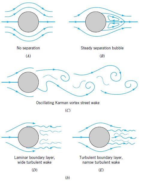
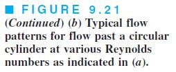
7 QUESTION 5 a. Describe the character of flow past an object The flow past a blunt object (such as a circular cylinder) varies with Reynolds number. In general, the larger the Reynolds number, the smaller the region (boundary layer) of the flow field in which viscous effects are important. For objects that are not sufficiently streamlined, however, an additional characteristic of the flow is observed. This is termed flow separation and is illustrated in Fig Low Reynolds number flow past a circular cylinder is characterized by the fact that the presence of the cylinder and the accompanying viscous effects are felt throughout a relatively large portion of the flow field. As is indicated in Fig. 9.6a, for Re 0.1 the viscous effects are important several diameters in any direction from the cylinder. A somewhat surprising characteristic of this flow is that the streamlines are essentially symmetric about the center of the cylinder the streamline pattern is the same in front of the cylinder as it is behind the cylinder. As the Reynolds number is increased, the region ahead of the cylinder in which viscous effects are important becomes smaller, with the viscous region extending only a short distance ahead of the cylinder (boundary layer region). The viscous effects are convected downstream and the flow loses its symmetry. Another characteristic of external flows becomes important - the flow separates from the body at the separation location as indicated in Fig. 9.6b. With the increase in Reynolds number, the fluid inertia becomes more important and at some location on the body, denoted the separation location, the fluid s inertia is such that it cannot follow the curved path around to the rear of the body. The result is a separation bubble behind the cylinder in which some of the fluid is actually flowing upstream, against the direction of the up-stream flow. At still larger Reynolds numbers, the area affected by the viscous forces is forced farther downstream until it involves only a thin ( D) boundary layer on the front portion of the cylinder and an irregular, unsteady (perhaps turbulent) wake region that extends far down-stream of the cylinder. The fluid in the region outside of the boundary layer and wake region flows as if it were inviscid. Of course, the fluid viscosity is the same throughout the entire flow field. Whether viscous effects are important or not depends on which region of the flow field we consider. The velocity gradients within the boundary layer and wake regions are much larger than those in the remainder of the flow field. Since the shear stress (i.e., viscous effect) is the product of the fluid viscosity and the velocity gradient, it follows that viscous effects are confined to the boundary layer and wake regions. The characteristics described in Fig 9.6 are typical of flows past blunt bodies. The nature of the flow depends strongly on the Reynolds number. Most familiar flows are similar to the large Reynolds number flows depicted in Fig 9.6c, rather than the low Reynolds number flow situations.

8 FIGURE 9.6 Character of the steady, viscous flow past a circular cylinder: (a) low Reynolds number flow, (b) moderate Reynolds number flow, (c) large Reynolds number flow. b. Distinguish the two components of the Drag force and explain their physical origin. For two dimensional objects, the drag is composed of a frictional component, related to viscous shearing in boundary layers, and pressure drag, which is related to the pressure differential between the fore and aft of the body. The character of the flow dictates the relative importance of the two components, i.e. whether the flow separates or remains attached to the object. The main characteristic of a separated flow is a separation bubble/region behind the object in which some of the fluid is actually flowing upstream, against the direction of the upstream flow (see figure). Because of separation, the average pressure on the rear half of the body is considerably less than that on the front half. Thus a large pressure drag is developed and the viscous shear drag may be quite small. c. Explain the meaning of Streamline and Bluff bodies and give examples. A Streamline body is defined as a body for which the major contribution of the drag force results directly from viscous or skin friction of the fluid on the body. Streamline bodies are slender and do not distort the streamlines of the flow so that the viscous boundary layer is attached over their entire surface. Examples: airfoil, horizontal flat plate, falling droplet. A Bluff (non-streamline) body is defined as the body for which the major contribution to the drag force is due to the low pressure in the separated region (the wake/bubble). The shape of the body produces an adverse pressure gradient which results in flow separation. Examples: Sphere, body of circular or rectangular cross-section, stalled airfoil (airfoil inclined at high angle)


9 QUESTION 6 5 At Reynolds numbers Re 10 the drag coefficient of a spherical object is CD 0.4, while for the object below is CD Give a physical explanation of these experimental results. The above body is streamlined while the sphere is considered to be a bluff body. See previous question for explanation. Find the ratio of the diameters such that the two objects would experience the same drag force. 10D The ratio of the diameters can be obtained as follows: The drag experienced by the two objects must be equal hence FD FD U A C 2 D U A 2 CD where subscript 2 corresponds to the droplet-like shape above U A 0.4 U A The two objects are immerced in a fluid of the same velocity hence A 1 D2 A D


10 QUESTION 7 Do you expect the drag on the object shown in Figure 1 to be less when the wind blows from right to left or when it blows from left to right. Explain. Figure 1: Object for Question 1

11 QUESTION 8 Describe the physical mechanism of flow separation. Pressure gradient is one of the factors that influences a flow immensely. It is easy to see that the shear stress caused by viscosity has a retarding effect upon the flow. This effect can however be overcome if there is a negative pressure gradient offered to the flow. A negative pressure gradient is termed a Favourable pressure gradient. Such a gradient enables the flow. A positive pressure gradient has the opposite effect and is termed an Adverse Pressure Gradient. Fluid might find it difficult to negotiate an adverse pressure gradient. Sometimes, we say the fluid has to climb the pressure hill. Figure 6.4 : Separation of flow over a curved surface One of the severe effects of an adverse pressure gradient is to separate the flow. Consider flow past a curved surface as shown in Figure 6.4. The geometry of the surface is such that we have a favourable gradient in pressure to start with and up to a point P. The negative pressure gradient will counteract the retarding effect of the shear stress (which is due to viscosity) in the boundary layer. For the geometry considered we have a an adverse pressure gradient downstream of P. Now the adverse pressure gradient begins to retard. This effect is felt more strongly in the regions close to the wall where the momentum is lower than in the regions near the free stream. As indicated in the figure, the velocity near the wall reduces and the boundary layer thickens. A continuous retardation of flow brings the wall shear stress at the point S on the wall to zero. From this point onwards the shear stress becomes negative and the flow reverses and a region of recirculating flow develops. We see that the flow no longer follows the contour of the body. We say that the flow has separated. The point S where the shear stress is zero is called the Point of Separation. Depending on the flow conditions the recirculating flow might terminate and the flow may become reattached to the body. A separation bubble is formed. There are a variety of factors that could influence this reattachment. The pressure gradient may be now favourable due to body geometry and other reasons. The other factor is that the flow initially laminar may undergo transition within the bubble and may become turbulent. A turbulent flow has more energy and momentum than a laminar flow. This can kill separation and the flow may reattach. A short bubble may not be of much consequence.

12 QUESTION 9 a. The pressure distribution around the surface of a cylinder due to an inviscid uniform flow at the far field is ps po U 1 4sin. 2 b. Detemine the drag force and comment. Based on the inviscid results there is no drag acting on the cylinder. However, experiments suggest that there is a finite drag due to: (i) viscous effects produced in the boundary layer near the surface giving rise to shear drag and (ii) pressure differences between the front and the back of the body due to flow separation. c. Based on the above result for the pressure gradient, explain the physical mechanisms of flow separation. The pressure distribution indicated in the figure is imposed on the boundary layer flow along the surface of the cylinder. This pressure distribution along the cylinder is such that the stationary fluid at the nose of the cylinder ( U 0 at = 0) is accelerated to its maximum velocity back to zero velocity at the rear of the cylinder ( 2 at =90 and then decelerated o U fs U ) o ( U fs 0 at =180 ). fs Figure 9.16: Inviscid flow past a circular cylinder: (a) streamlines for the flow if there were no viscous effects, (b) pressure distribution on the cylinder s surface, (c) free-stream velocity on the cylinder s surface. This is accomplished by a balance between pressure and inertia effects; viscous effects are absent for the inviscid flow outside the boundary layer. Physically, in the absence of viscous effects, a fluid particle travelling from the front to the back of the cylinder coasts down the pressure hill (from point A to C in the figure) and then back up the hill to (from point C to F) without any loss of energy. There is an exchange between kinetic and pressure energy, but there are no energy losses. The same pressure distribution is imposed on the viscous fluid within the boundary layer. The decrease in pressure in the direction of flow along the front half of the cylinder is termed a favorable pressure gradient. The increase in
13 pressure in the direction of flow along the rear half of the cylinder is termed an adverse pressure gradient. Consider a fluid particle within the boundary layer. In its attempt to flow from A to F it experiences the same pressure distribution as the particles in the free stream immediately outside the boundary layer the inviscid flow field pressure. However, because of the viscous effects involved, the particle in the boundary layer experiences a loss of energy as it flows along. This loss means that the particle does not have enough energy to coast all of the way up the pressure hill (from C to F) and to reach point F at the rear of the cylinder. This conclusion can also be obtained from the concept that due to viscous effects the particle at C does not have enough momentum to allow it to coast up the pressure hill to F. The fluid within the boundary layer does not have such an energy supply. Thus, the fluid flows against the increasing pressure as far as it can, at which point the boundary layer separates from (lifts off) the surface. At the separation location, the velocity gradient at the wall and the wall shear stress are zero. Beyond that there is reverse flow in the boundary layer (see Munson pg 570).

14 QUESTION 10 Describe the dependence of the Reynolds number ( Re ) on the Drag Coefficient ( C D ). For very small Reynolds number flows, the drag coefficient varies linearly with the Reynolds number. For most objects, the low Reynolds number flow results are valid up to a Reynolds number of about 1.
15

16 QUESTION 11 a. Explain the characteristics of the flow over an airfoil The structure of the flow field past a circular cylinder is completely different for a zero viscosity fluid than it is for a viscous fluid, no matter how small the viscosity is, provided it is not zero. This is due to boundary layer separation. Similar concepts hold for other shaped bodies as well. The flow past an airfoil at zero angle of attack (the angle between the up-stream flow and the axis of the object) is shown in Fig. 9.18a; flow past the same airfoil at a 5 0 angle of attack is shown in Fig. 9.18b. Over the front portion of the airfoil the pressure decreases in the direction of flow a favorable pressure gradient. Over the rear portion the pressure increases in the direction of flow an adverse pressure gradient. If the adverse pressure gradient is not too great (because the body is not too thick in some sense), the boundary layer fluid can flow into the slightly increasing pressure region (i.e., from C to the trailing edge in Fig. 9.18a) without separating from the surface. However, if the pressure gradient is too adverse (because the angle of attack is too large, or the body is thick ), the boundary layer will separate from the surface as indicated in Fig. 9.18b. Such situations can lead to the catastrophic loss of lift called stall, Figure 9.18: Flow visualization photographs of flow past an airfoil (the boundary layer velocity profiles for the points indicated are similar to those indicated in Fig. (b): (a) zero angle of attack, no separation, (b) angle of attack, flow separation. Dye in water.

17 On aerofoils sometimes the separation occurs near the leading edge and gives rise to a short bubble. What can be dangerous is the separation occurring more towards the trailing edge and the flow not reattaching. In this situation the separated region merges with the wake and may result in stall of the aerofoil (loss of lift). Figure 6.5 : Separation bubble over an aerofoil b. What is the effect of flow separation on the drag force and lift force of an airfoil? Similar to flow over a sphere, for a completely attached flow over an airfoil, the pressure acting on the rear surface gives rise to a force in the forward direction which completely counteracts the pressure acting on the front surface producing a force in the rearward direction, resulting in zero pressure drag. However, if the flow is partially separated over the rear surface, the pressure on the rear surface pushing forward will be smaller than the fully attached case, giving rise to a net pressure drag on the airfoil. The aerodynamic lift (vertical force) is derived from the net component of the pressure distribution in the vertical direction. High lift is obtained when the pressure on the bottom surface is large and the pressure on the top surface is small. Separation does not affect the bottom surface pressure distribution but rather produces a relatively higher pressure on the top surface. There is a higher pressure pushing down, hence reducing lift. The loss of lift is called stall. See also: Introduction to Flight, John D. Anderson Jr., 6 th Edition, McGraw-Hill, Higher Education, pages
Lecture-4. Flow Past Immersed Bodies
 Lecture-4 Flow Past Immersed Bodies Learning objectives After completing this lecture, you should be able to: Identify and discuss the features of external flow Explain the fundamental characteristics
FLUID MECHANICS. Chapter 9 Flow over Immersed Bodies
 FLUID MECHANICS Chapter 9 Flow over Immersed Bodies CHAP 9. FLOW OVER IMMERSED BODIES CONTENTS 9.1 General External Flow Characteristics 9.3 Drag 9.4 Lift 9.1 General External Flow Characteristics 9.1.1
 UNIT IV BOUNDARY LAYER AND FLOW THROUGH PIPES Definition of boundary layer Thickness and classification Displacement and momentum thickness Development of laminar and turbulent flows in circular pipes
Active Control of Separated Cascade Flow
 Chapter 5 Active Control of Separated Cascade Flow In this chapter, the possibility of active control using a synthetic jet applied to an unconventional axial stator-rotor arrangement is investigated.
Visualization of flow pattern over or around immersed objects in open channel flow.
 EXPERIMENT SEVEN: FLOW VISUALIZATION AND ANALYSIS I OBJECTIVE OF THE EXPERIMENT: Visualization of flow pattern over or around immersed objects in open channel flow. II THEORY AND EQUATION: Open channel:
Day 24: Flow around objects
 Day 24: Flow around objects case 1) fluid flowing around a fixed object (e.g. bridge pier) case 2) object travelling within a fluid (cars, ships planes) two forces are exerted between the fluid and the
Applied Fluid Mechanics
 Applied Fluid Mechanics 1. The Nature of Fluid and the Study of Fluid Mechanics 2. Viscosity of Fluid 3. Pressure Measurement 4. Forces Due to Static Fluid 5. Buoyancy and Stability 6. Flow of Fluid and
UNIT 4 FORCES ON IMMERSED BODIES. Lecture-01
 1 UNIT 4 FORCES ON IMMERSED BODIES Lecture-01 Forces on immersed bodies When a body is immersed in a real fluid, which is flowing at a uniform velocity U, the fluid will exert a force on the body. The
Department of Energy Sciences, LTH
 Department of Energy Sciences, LTH MMV11 Fluid Mechanics LABORATION 1 Flow Around Bodies OBJECTIVES (1) To understand how body shape and surface finish influence the flow-related forces () To understand
1. Introduction, tensors, kinematics
 1. Introduction, tensors, kinematics Content: Introduction to fluids, Cartesian tensors, vector algebra using tensor notation, operators in tensor form, Eulerian and Lagrangian description of scalar and
Momentum (Newton s 2nd Law of Motion)
") Dr. Nikos J. Mourtos AE 160 / ME 111 Momentum (Newton s nd Law of Motion) Case 3 Airfoil Drag A very important application of Momentum in aerodynamics and hydrodynamics is the calculation of the drag of
Dr. Nikos J. Mourtos AE 160 / ME 111 Momentum (Newton s nd Law of Motion) Case 3 Airfoil Drag A very important application of Momentum in aerodynamics and hydrodynamics is the calculation of the drag of
Lecture 7 Boundary Layer
 SPC 307 Introduction to Aerodynamics Lecture 7 Boundary Layer April 9, 2017 Sep. 18, 2016 1 Character of the steady, viscous flow past a flat plate parallel to the upstream velocity Inertia force = ma
Fluid Mechanics II 3 credit hour. External flows. Course teacher Dr. M. Mahbubur Razzaque Professor Department of Mechanical Engineering BUET 1
 COURSE NUMBER: ME 323 Fluid Mechanics II 3 credit hour External flows Course teacher Dr. M. Mahbubur Razzaque Professor Department of Mechanical Engineering BUET 1 External flows The study of external
Bluff Body, Viscous Flow Characteristics ( Immersed Bodies)
") Bluff Body, Viscous Flow Characteristics ( Immersed Bodies) In general, a body immersed in a flow will experience both externally applied forces and moments as a result of the flow about its external surfaces.
Bluff Body, Viscous Flow Characteristics ( Immersed Bodies) In general, a body immersed in a flow will experience both externally applied forces and moments as a result of the flow about its external surfaces.
Fluid Mechanics. Chapter 9 Surface Resistance. Dr. Amer Khalil Ababneh
 Fluid Mechanics Chapter 9 Surface Resistance Dr. Amer Khalil Ababneh Wind tunnel used for testing flow over models. Introduction Resistances exerted by surfaces are a result of viscous stresses which create
Boundary-Layer Theory
 Hermann Schlichting Klaus Gersten Boundary-Layer Theory With contributions from Egon Krause and Herbert Oertel Jr. Translated by Katherine Mayes 8th Revised and Enlarged Edition With 287 Figures and 22
Lab Reports Due on Monday, 11/24/2014
 AE 3610 Aerodynamics I Wind Tunnel Laboratory: Lab 4 - Pressure distribution on the surface of a rotating circular cylinder Lab Reports Due on Monday, 11/24/2014 Objective In this lab, students will be
PART 1B EXPERIMENTAL ENGINEERING. SUBJECT: FLUID MECHANICS & HEAT TRANSFER LOCATION: HYDRAULICS LAB (Gnd Floor Inglis Bldg) BOUNDARY LAYERS AND DRAG
 BOUNDARY LAYERS AND DRAG") 1 PART 1B EXPERIMENTAL ENGINEERING SUBJECT: FLUID MECHANICS & HEAT TRANSFER LOCATION: HYDRAULICS LAB (Gnd Floor Inglis Bldg) EXPERIMENT T3 (LONG) BOUNDARY LAYERS AND DRAG OBJECTIVES a) To measure the velocity
1 PART 1B EXPERIMENTAL ENGINEERING SUBJECT: FLUID MECHANICS & HEAT TRANSFER LOCATION: HYDRAULICS LAB (Gnd Floor Inglis Bldg) EXPERIMENT T3 (LONG) BOUNDARY LAYERS AND DRAG OBJECTIVES a) To measure the velocity
Simulating Drag Crisis for a Sphere Using Skin Friction Boundary Conditions
 Simulating Drag Crisis for a Sphere Using Skin Friction Boundary Conditions Johan Hoffman May 14, 2006 Abstract In this paper we use a General Galerkin (G2) method to simulate drag crisis for a sphere,
Introduction to Turbulence AEEM Why study turbulent flows?
 Introduction to Turbulence AEEM 7063-003 Dr. Peter J. Disimile UC-FEST Department of Aerospace Engineering Peter.disimile@uc.edu Intro to Turbulence: C1A Why 1 Most flows encountered in engineering and
Chapter 3 Lecture 8. Drag polar 3. Topics. Chapter-3
 Chapter 3 ecture 8 Drag polar 3 Topics 3.2.7 Boundary layer separation, adverse pressure gradient and favourable pressure gradient 3.2.8 Boundary layer transition 3.2.9 Turbulent boundary layer over a
E80. Fluid Measurement The Wind Tunnel Lab. Experimental Engineering.
 Fluid Measurement The Wind Tunnel Lab http://twistedsifter.com/2012/10/red-bull-stratos-space-jump-photos/ Feb. 13, 2014 Outline Wind Tunnel Lab Objectives Why run wind tunnel experiments? How can we use
FLUID FORCES ON NON-STREAMLINE BODIES BACKGROUND NOTES AND DESCRIPTION OF THE FLOW PHENOMENA
 FLUID FORCES ON NON-STREAMLINE BODIES BACKGROUND NOTES AND DESCRIPTION OF THE FLOW PHENOMENA 1. INTRODUCTION The purpose of this Item is to provide background information which will assist the user of
UNIT II CONVECTION HEAT TRANSFER
 UNIT II CONVECTION HEAT TRANSFER Convection is the mode of heat transfer between a surface and a fluid moving over it. The energy transfer in convection is predominately due to the bulk motion of the fluid
What we know about Fluid Mechanics. What we know about Fluid Mechanics
 What we know about Fluid Mechanics 1. Survey says. 3. Image from: www.axs.com 4. 5. 6. 1 What we know about Fluid Mechanics 1. MEB (single input, single output, steady, incompressible, no rxn, no phase
Given the water behaves as shown above, which direction will the cylinder rotate?
 water stream fixed but free to rotate Given the water behaves as shown above, which direction will the cylinder rotate? ) Clockwise 2) Counter-clockwise 3) Not enough information F y U 0 U F x V=0 V=0
BLUFF-BODY AERODYNAMICS
 International Advanced School on WIND-EXCITED AND AEROELASTIC VIBRATIONS OF STRUCTURES Genoa, Italy, June 12-16, 2000 BLUFF-BODY AERODYNAMICS Lecture Notes by Guido Buresti Department of Aerospace Engineering
Convection. forced convection when the flow is caused by external means, such as by a fan, a pump, or atmospheric winds.
 Convection The convection heat transfer mode is comprised of two mechanisms. In addition to energy transfer due to random molecular motion (diffusion), energy is also transferred by the bulk, or macroscopic,
Principles of Convection
 Principles of Convection Point Conduction & convection are similar both require the presence of a material medium. But convection requires the presence of fluid motion. Heat transfer through the: Solid
COURSE ON VEHICLE AERODYNAMICS Prof. Tamás Lajos University of Rome La Sapienza 1999
 COURSE ON VEHICLE AERODYNAMICS Prof. Tamás Lajos University of Rome La Sapienza 1999 1. Introduction Subject of the course: basics of vehicle aerodynamics ground vehicle aerodynamics examples in car, bus,
Tutorial 10. Boundary layer theory
 Tutorial 10 Boundary layer theory 1. If the velocity distribution law in a laminar boundary layer over a flat plate is assumes to be of the form, determine the velocity distribution law. At y = 0, u= 0
Fluid Mechanics Prof. T. I. Eldho Department of Civil Engineering Indian Institute of Technology, Bombay
 Fluid Mechanics Prof. T. I. Eldho Department of Civil Engineering Indian Institute of Technology, Bombay Lecture No. # 35 Boundary Layer Theory and Applications Welcome back to the video course on fluid
Steady waves in compressible flow
 Chapter Steady waves in compressible flow. Oblique shock waves Figure. shows an oblique shock wave produced when a supersonic flow is deflected by an angle. Figure.: Flow geometry near a plane oblique
Aerodynamics. High-Lift Devices
 High-Lift Devices Devices to increase the lift coefficient by geometry changes (camber and/or chord) and/or boundary-layer control (avoid flow separation - Flaps, trailing edge devices - Slats, leading
BOUNDARY LAYER FLOWS HINCHEY
 BOUNDARY LAYER FLOWS HINCHEY BOUNDARY LAYER PHENOMENA When a body moves through a viscous fluid, the fluid at its surface moves with it. It does not slip over the surface. When a body moves at high speed,
Given a stream function for a cylinder in a uniform flow with circulation: a) Sketch the flow pattern in terms of streamlines.
 Sketch the flow pattern in terms of streamlines.") Question Given a stream function for a cylinder in a uniform flow with circulation: R Γ r ψ = U r sinθ + ln r π R a) Sketch the flow pattern in terms of streamlines. b) Derive an expression for the angular
Question Given a stream function for a cylinder in a uniform flow with circulation: R Γ r ψ = U r sinθ + ln r π R a) Sketch the flow pattern in terms of streamlines. b) Derive an expression for the angular
External Flow and Boundary Layer Concepts
 1 2 Lecture (8) on Fayoum University External Flow and Boundary Layer Concepts By Dr. Emad M. Saad Mechanical Engineering Dept. Faculty of Engineering Fayoum University Faculty of Engineering Mechanical
Numerical Investigation of the Fluid Flow around and Past a Circular Cylinder by Ansys Simulation
 , pp.49-58 http://dx.doi.org/10.1457/ijast.016.9.06 Numerical Investigation of the Fluid Flow around and Past a Circular Cylinder by Ansys Simulation Mojtaba Daneshi Department of Mechanical Engineering,
Flight Vehicle Terminology
 Flight Vehicle Terminology 1.0 Axes Systems There are 3 axes systems which can be used in Aeronautics, Aerodynamics & Flight Mechanics: Ground Axes G(x 0, y 0, z 0 ) Body Axes G(x, y, z) Aerodynamic Axes
1. Fluid Dynamics Around Airfoils
 1. Fluid Dynamics Around Airfoils Two-dimensional flow around a streamlined shape Foces on an airfoil Distribution of pressue coefficient over an airfoil The variation of the lift coefficient with the
Relaminerization of a Highly Accelerated Flow on a Convex Curvature
 Relaminerization of a Highly Accelerated Flow on a Convex Curvature Abstract Relaminarization of turbulent flow is a process by which the mean flow reverts to an effectively laminar state. The phenomenon
SPC Aerodynamics Course Assignment Due Date Monday 28 May 2018 at 11:30
 SPC 307 - Aerodynamics Course Assignment Due Date Monday 28 May 2018 at 11:30 1. The maximum velocity at which an aircraft can cruise occurs when the thrust available with the engines operating with the
Mechanical Engineering Programme of Study
 Mechanical Engineering Programme of Study Fluid Mechanics Instructor: Marios M. Fyrillas Email: eng.fm@fit.ac.cy SOLVED EXAMPLES ON VISCOUS FLOW 1. Consider steady, laminar flow between two fixed parallel
TURBULENT FLOW ACROSS A ROTATING CYLINDER WITH SURFACE ROUGHNESS
 HEFAT2014 10 th International Conference on Heat Transfer, Fluid Mechanics and Thermodynamics 14 16 July 2014 Orlando, Florida TURBULENT FLOW ACROSS A ROTATING CYLINDER WITH SURFACE ROUGHNESS Everts, M.,
Fluid Mechanics Prof. T.I. Eldho Department of Civil Engineering Indian Institute of Technology, Bombay. Lecture - 17 Laminar and Turbulent flows
 Fluid Mechanics Prof. T.I. Eldho Department of Civil Engineering Indian Institute of Technology, Bombay Lecture - 17 Laminar and Turbulent flows Welcome back to the video course on fluid mechanics. In
Validation 3. Laminar Flow Around a Circular Cylinder
 Validation 3. Laminar Flow Around a Circular Cylinder 3.1 Introduction Steady and unsteady laminar flow behind a circular cylinder, representing flow around bluff bodies, has been subjected to numerous
In Chapter 6 we considered the general and theoretical aspects of forced
 cen58933_ch07.qxd 9/4/2002 12:12 PM Page 367 EXTERNAL FORCED CONVECTION CHAPTER 7 In Chapter 6 we considered the general and theoretical aspects of forced convection, with emphasis on differential formulation
Friction Factors and Drag Coefficients
 Levicky 1 Friction Factors and Drag Coefficients Several equations that we have seen have included terms to represent dissipation of energy due to the viscous nature of fluid flow. For example, in the
FLOW SEPARATION. Aerodynamics Bridge-Pier Design Combustion Chambers Human Blood Flow Building Design Etc.
 FLOW SEPARATION Aerodynamics Bridge-Pier Design Combustion Chambers Human Blood Flow Building Design Etc. (Form Drag, Pressure Distribution, Forces and Moments, Heat And Mass Transfer, Vortex Shedding)
ROAD MAP... D-1: Aerodynamics of 3-D Wings D-2: Boundary Layer and Viscous Effects D-3: XFLR (Aerodynamics Analysis Tool)
") AE301 Aerodynamics I UNIT D: Applied Aerodynamics ROAD MAP... D-1: Aerodynamics o 3-D Wings D-2: Boundary Layer and Viscous Eects D-3: XFLR (Aerodynamics Analysis Tool) AE301 Aerodynamics I : List o Subjects
AE301 Aerodynamics I UNIT D: Applied Aerodynamics ROAD MAP... D-1: Aerodynamics o 3-D Wings D-2: Boundary Layer and Viscous Eects D-3: XFLR (Aerodynamics Analysis Tool) AE301 Aerodynamics I : List o Subjects
Syllabus for AE3610, Aerodynamics I
 Syllabus for AE3610, Aerodynamics I Current Catalog Data: AE 3610 Aerodynamics I Credit: 4 hours A study of incompressible aerodynamics of flight vehicles with emphasis on combined application of theory
External Forced Convection. Copyright The McGraw-Hill Companies, Inc. Permission required for reproduction or display.
 External Forced Convection Copyright The McGraw-Hill Companies, Inc. Permission required for reproduction or display. Drag and Heat Transfer in External flow Fluid flow over solid bodies is responsible
Detailed Outline, M E 320 Fluid Flow, Spring Semester 2015
 Detailed Outline, M E 320 Fluid Flow, Spring Semester 2015 I. Introduction (Chapters 1 and 2) A. What is Fluid Mechanics? 1. What is a fluid? 2. What is mechanics? B. Classification of Fluid Flows 1. Viscous
FLUID MECHANICS PROF. DR. METİN GÜNER COMPILER
 FLUID MECHANICS PROF. DR. METİN GÜNER COMPILER ANKARA UNIVERSITY FACULTY OF AGRICULTURE DEPARTMENT OF AGRICULTURAL MACHINERY AND TECHNOLOGIES ENGINEERING 1 5. FLOW IN PIPES 5.1.3. Pressure and Shear Stress
Iran University of Science & Technology School of Mechanical Engineering Advance Fluid Mechanics
 1. Consider a sphere of radius R immersed in a uniform stream U0, as shown in 3 R Fig.1. The fluid velocity along streamline AB is given by V ui U i x 1. 0 3 Find (a) the position of maximum fluid acceleration
Laminar Flow. Chapter ZERO PRESSURE GRADIENT
 Chapter 2 Laminar Flow 2.1 ZERO PRESSRE GRADIENT Problem 2.1.1 Consider a uniform flow of velocity over a flat plate of length L of a fluid of kinematic viscosity ν. Assume that the fluid is incompressible
τ du In his lecture we shall look at how the forces due to momentum changes on the fluid and viscous forces compare and what changes take place.
 4. Real fluids The flow of real fluids exhibits viscous effect, that is they tend to stick to solid surfaces and have stresses within their body. You might remember from earlier in the course Newtons law
Experimental and Numerical Investigation of Flow over a Cylinder at Reynolds Number 10 5
 Journal of Modern Science and Technology Vol. 1. No. 1. May 2013 Issue. Pp.52-60 Experimental and Numerical Investigation of Flow over a Cylinder at Reynolds Number 10 5 Toukir Islam and S.M. Rakibul Hassan
Prof. Scalo Prof. Vlachos Prof. Ardekani Prof. Dabiri 08:30 09:20 A.M 10:30 11:20 A.M. 1:30 2:20 P.M. 3:30 4:20 P.M.
 Page 1 Neatly print your name: Signature: (Note that unsigned exams will be given a score of zero.) Circle your lecture section (-1 point if not circled, or circled incorrectly): Prof. Scalo Prof. Vlachos
Mestrado Integrado em Engenharia Mecânica Aerodynamics 1 st Semester 2012/13
 Mestrado Integrado em Engenharia Mecânica Aerodynamics 1 st Semester 212/13 Exam 2ª época, 2 February 213 Name : Time : 8: Number: Duration : 3 hours 1 st Part : No textbooks/notes allowed 2 nd Part :
ELECTROMAGNETIC CONTROL OF FLOW SEPARATION
 ELECTROMAGNETIC CONTROL OF FLOW SEPARATION Tom Weier, Gerd Mutschke, we Fey, Vjatcheslav Avilov, Gunter Gerbeth 1. Introduction The performance of fluid mechanical devices is often limited by flow separation.
Basic Fluid Mechanics
 Basic Fluid Mechanics Chapter 6A: Internal Incompressible Viscous Flow 4/16/2018 C6A: Internal Incompressible Viscous Flow 1 6.1 Introduction For the present chapter we will limit our study to incompressible
58:160 Intermediate Fluid Mechanics Bluff Body Professor Fred Stern Fall 2014
 Professor Fred Stern Fall 04 Chapter 7 Bluff Body Fluid flows are broadly categorized:. Internal flows such as ducts/pipes, turbomachinery, open channel/river, which are bounded by walls or fluid interfaces:
Module3: Waves in Supersonic Flow Lecture14: Waves in Supersonic Flow (Contd.)
") 1 Module3: Waves in Supersonic Flow Lecture14: Waves in Supersonic Flow (Contd.) Mach Reflection: The appearance of subsonic regions in the flow complicates the problem. The complications are also encountered
1 Module3: Waves in Supersonic Flow Lecture14: Waves in Supersonic Flow (Contd.) Mach Reflection: The appearance of subsonic regions in the flow complicates the problem. The complications are also encountered
Problem 4.3. Problem 4.4
 Problem 4.3 Problem 4.4 Problem 4.5 Problem 4.6 Problem 4.7 This is forced convection flow over a streamlined body. Viscous (velocity) boundary layer approximations can be made if the Reynolds number Re
Detailed Outline, M E 521: Foundations of Fluid Mechanics I
 Detailed Outline, M E 521: Foundations of Fluid Mechanics I I. Introduction and Review A. Notation 1. Vectors 2. Second-order tensors 3. Volume vs. velocity 4. Del operator B. Chapter 1: Review of Basic
Forced Convection Around Obstacles
 Chapter 4 Forced Convection Around Obstacles 4.1. Description of the flow This chapter is devoted to heat transfer on bodies immersed in a stream. We consider a solid characterized by the length scale
SENTHIL SELIYAN ELANGO ID: UB3016SC17508 AIU HYDRAULICS (FLUID DYNAMICS)
") SENTHIL SELIYAN ELANGO ID: UB3016SC17508 AIU HYDRAULICS (FLUID DYNAMICS) ATLANTIC INTERNATIONAL UNIVERSITY INTRODUCTION Real fluids The flow of real fluids exhibits viscous effect, which are they tend
SENTHIL SELIYAN ELANGO ID: UB3016SC17508 AIU HYDRAULICS (FLUID DYNAMICS) ATLANTIC INTERNATIONAL UNIVERSITY INTRODUCTION Real fluids The flow of real fluids exhibits viscous effect, which are they tend
MDTS 5705 : Aerodynamics & Propulsion Lecture 2 : Missile lift and drag. G. Leng, MDTS, NUS
 MDTS 5705 : Aerodynamics & Propulsion Lecture 2 : Missile lift and drag 2.1. The design of supersonic airfoils For efficient lift generation at subsonic speeds, airfoils look like : So why can t a similar
Chapter 9 Flow over Immersed Bodies
 57:00 Mechanics of Fluids and Transport Processes Chapter 9 Professor Fred Stern Fall 009 1 Chapter 9 Flow over Immersed Bodies Fluid flows are broadly categorized: 1. Internal flows such as ducts/pipes,
Figure 3: Problem 7. (a) 0.9 m (b) 1.8 m (c) 2.7 m (d) 3.6 m
 0.9 m (b) 1.8 m (c) 2.7 m (d) 3.6 m") 1. For the manometer shown in figure 1, if the absolute pressure at point A is 1.013 10 5 Pa, the absolute pressure at point B is (ρ water =10 3 kg/m 3, ρ Hg =13.56 10 3 kg/m 3, ρ oil = 800kg/m 3 ): (a)
1. For the manometer shown in figure 1, if the absolute pressure at point A is 1.013 10 5 Pa, the absolute pressure at point B is (ρ water =10 3 kg/m 3, ρ Hg =13.56 10 3 kg/m 3, ρ oil = 800kg/m 3 ): (a)
Numerical Investigation of Shock wave Turbulent Boundary Layer Interaction over a 2D Compression Ramp
 Advances in Aerospace Science and Applications. ISSN 2277-3223 Volume 4, Number 1 (2014), pp. 25-32 Research India Publications http://www.ripublication.com/aasa.htm Numerical Investigation of Shock wave
The Bernoulli Equation
 The Bernoulli Equation The most used and the most abused equation in fluid mechanics. Newton s Second Law: F = ma In general, most real flows are 3-D, unsteady (x, y, z, t; r,θ, z, t; etc) Let consider
PEMP ACD2505. M.S. Ramaiah School of Advanced Studies, Bengaluru
 Two-Dimensional Potential Flow Session delivered by: Prof. M. D. Deshpande 1 Session Objectives -- At the end of this session the delegate would have understood PEMP The potential theory and its application
Brenda M. Kulfan, John E. Bussoletti, and Craig L. Hilmes Boeing Commercial Airplane Group, Seattle, Washington, 98124
 AIAA--2007-0684 Pressures and Drag Characteristics of Bodies of Revolution at Near Sonic Speeds Including the Effects of Viscosity and Wind Tunnel Walls Brenda M. Kulfan, John E. Bussoletti, and Craig
Numerical Investigation of Wind Tunnel Wall Effects on a Supersonic Finned Missile
 16 th International Conference on AEROSPACE SCIENCES & AVIATION TECHNOLOGY, ASAT - 16 May 26-28, 2015, E-Mail: asat@mtc.edu.eg Military Technical College, Kobry Elkobbah, Cairo, Egypt Tel : +(202) 24025292
Chapter 5 Phenomena of laminar-turbulent boundary layer transition (including free shear layers)
") Chapter 5 Phenomena of laminar-turbulent boundary layer transition (including free shear layers) T-S Leu May. 3, 2018 Chapter 5: Phenomena of laminar-turbulent boundary layer transition (including free
Chapter 5 Phenomena of laminar-turbulent boundary layer transition (including free shear layers) T-S Leu May. 3, 2018 Chapter 5: Phenomena of laminar-turbulent boundary layer transition (including free
All that begins... peace be upon you
 All that begins... peace be upon you Faculty of Mechanical Engineering Department of Thermo Fluids SKMM 2323 Mechanics of Fluids 2 «An excerpt (mostly) from White (2011)» ibn Abdullah May 2017 Outline
10.52 Mechanics of Fluids Spring 2006 Problem Set 3
 10.52 Mechanics of Fluids Spring 2006 Problem Set 3 Problem 1 Mass transfer studies involving the transport of a solute from a gas to a liquid often involve the use of a laminar jet of liquid. The situation
Numerical study of the effects of trailing-edge bluntness on highly turbulent hydro-foil flows
 Numerical study of the effects of trailing-edge bluntness on highly turbulent hydro-foil flows T. Do L. Chen J. Tu B. Anderson 7 November 2005 Abstract Flow-induced noise from fully submerged lifting bodies
External Forced Convection :
 External Forced Convection : Flow over Bluff Objects (Cylinders, Spheres, Packed Beds) and Impinging Jets Chapter 7 Sections 7.4 through 7.8 7.4 The Cylinder in Cross Flow Conditions depend on special
DAY 19: Boundary Layer
 DAY 19: Boundary Layer flat plate : let us neglect the shape of the leading edge for now flat plate boundary layer: in blue we highlight the region of the flow where velocity is influenced by the presence
WALL ROUGHNESS EFFECTS ON SHOCK BOUNDARY LAYER INTERACTION FLOWS
 ISSN (Online) : 2319-8753 ISSN (Print) : 2347-6710 International Journal of Innovative Research in Science, Engineering and Technology An ISO 3297: 2007 Certified Organization, Volume 2, Special Issue
BERNOULLI EQUATION. The motion of a fluid is usually extremely complex.
 BERNOULLI EQUATION The motion of a fluid is usually extremely complex. The study of a fluid at rest, or in relative equilibrium, was simplified by the absence of shear stress, but when a fluid flows over
List of symbols. Latin symbols. Symbol Property Unit
 Abstract Aircraft icing continues to be a threat for modern day aircraft. Icing occurs when supercooled large droplets (SLD s) impinge on the body of the aircraft. These droplets can bounce off, freeze
6.1 Momentum Equation for Frictionless Flow: Euler s Equation The equations of motion for frictionless flow, called Euler s
 Chapter 6 INCOMPRESSIBLE INVISCID FLOW All real fluids possess viscosity. However in many flow cases it is reasonable to neglect the effects of viscosity. It is useful to investigate the dynamics of an
PHYSICAL MECHANISM OF CONVECTION
 Tue 8:54:24 AM Slide Nr. 0 of 33 Slides PHYSICAL MECHANISM OF CONVECTION Heat transfer through a fluid is by convection in the presence of bulk fluid motion and by conduction in the absence of it. Chapter
Experimental Investigation to Study Flow Characteristics over a Naca0018 Aerofoil and an Automobile Dome-A Comparative Study
 Experimental Investigation to Study Flow Characteristics over a Naca0018 Aerofoil and an Automobile Dome-A Comparative Study M. Sri Rama Murthy 1, A. V. S. S. K. S. Gupta 2 1 Associate professor, Department
Vortex Induced Vibrations
 Vortex Induced Vibrations By: Abhiroop Jayanthi Indian Institute of Technology, Delhi Some Questions! What is VIV? What are the details of a steady approach flow past a stationary cylinder? How and why
CEE 3310 External Flows (Boundary Layers & Drag, Nov. 12, Re 0.5 x x 1/2. Re 1/2
 CEE 3310 External Flows (Boundary Layers & Drag, Nov. 12, 2018 155 7.11 Review Momentum integral equation τ w = ρu 2 dθ dx Von Kármán assumed and found and δ x = 5.5 Rex 0.5 u(x, y) U = 2y δ y2 δ 2 δ =
Numerical study of battle damaged two-dimensional wings
 Advances in Fluid Mechanics IX 141 Numerical study of battle damaged two-dimensional wings S. Djellal, T. Azzam, M. Djellab & K. Lakkaichi Fluid Mechanics Laboratory Polytechnical School Bordj El Bahri,
φ(r, θ, t) = a 2 U(t) cos θ. (7.1)
 = a 2 U(t) cos θ. (7.1)") BioFluids Lectures 7-8: Slender Fish Added Mass for Lateral Motion At high Reynolds number, most of the effort required in swimming is pushing water out of the way, that is our energy goes in providing
BioFluids Lectures 7-8: Slender Fish Added Mass for Lateral Motion At high Reynolds number, most of the effort required in swimming is pushing water out of the way, that is our energy goes in providing
INSTITUTE OF AERONAUTICAL ENGINEERING (Autonomous) Dundigal, Hyderabad
 Dundigal, Hyderabad") INSTITUTE OF AERONAUTICAL ENGINEERING (Autonomous) Dundigal, Hyderabad - 500 043 AERONAUTICAL ENGINEERING TUTORIAL QUESTION BANK Course Name : LOW SPEED AERODYNAMICS Course Code : AAE004 Regulation : IARE
INSTITUTE OF AERONAUTICAL ENGINEERING (Autonomous) Dundigal, Hyderabad - 500 043 AERONAUTICAL ENGINEERING TUTORIAL QUESTION BANK Course Name : LOW SPEED AERODYNAMICS Course Code : AAE004 Regulation : IARE
The E80 Wind Tunnel Experiment the experience will blow you away. by Professor Duron Spring 2012
 The E80 Wind Tunnel Experiment the experience will blow you away by Professor Duron Spring 2012 Objectives To familiarize the student with the basic operation and instrumentation of the HMC wind tunnel
STUDY OF THE SECONDARY FLOW STRUCTURES CAUSED THE ADDITION FORWARD FACING STEP TURBULENCE GENERATED
 Advances and Applications in Fluid Mechanics 2015 Pushpa Publishing House, Allahabad, India Published Online: May 2015 http://dx.doi.org/10.17654/aafmjul2015_129_144 Volume 18, Number 1, 2015, Pages 129-144
MAE 101A. Homework 7 - Solutions 3/12/2018
 MAE 101A Homework 7 - Solutions 3/12/2018 Munson 6.31: The stream function for a two-dimensional, nonviscous, incompressible flow field is given by the expression ψ = 2(x y) where the stream function has
MODELING OF PLASMA ACTUATOR AND ITS EFFECT ON FLOW FIELD AROUND RECTANGULAR CYLINDER
 Indian J.Sci.Res.1(2) : 803-814, 2014 ISSN : 0976-2876 (Print) ISSN : 2250-0138(Online) MODELING OF PLASMA ACTUATOR AND ITS EFFECT ON FLOW FIELD AROUND RECTANGULAR CYLINDER SAEED KAVOUSFAR a, HOSSEIN MAHDAVY-MOGHADDAM
Applications of CFD in wind engineering, called computational wind engineering (CWE), have significantly
, have significantly") Validation of Computational Fluid Dynamics Technique for Turbulent Wind Flow Approach, Bluff Two-Dimensional Body Alfadhel B. Kasim 1, Dr. Salah R. Al Zaidee 2 1 Researcher, College of Engineering, Baghdad
Validation of Computational Fluid Dynamics Technique for Turbulent Wind Flow Approach, Bluff Two-Dimensional Body Alfadhel B. Kasim 1, Dr. Salah R. Al Zaidee 2 1 Researcher, College of Engineering, Baghdad
Chapter 14. Fluid Mechanics
 Chapter 14 Fluid Mechanics States of Matter Solid Has a definite volume and shape Liquid Has a definite volume but not a definite shape Gas unconfined Has neither a definite volume nor shape All of these
Department of Mechanical Engineering
 Department o Mehanial Engineering AMEE41 / ATO4 Aerodynamis Instrutor: Marios M. Fyrillas Email: eng.m@it.a.y Homework Assignment #4 QESTION 1 Consider the boundary layer low on a lat plate o width b (shown